EP2941386B1 - Verfahren und vorrichtung zur sicherung von gegenständen in ballenform - Google Patents
Verfahren und vorrichtung zur sicherung von gegenständen in ballenform Download PDFInfo
- Publication number
- EP2941386B1 EP2941386B1 EP13723562.8A EP13723562A EP2941386B1 EP 2941386 B1 EP2941386 B1 EP 2941386B1 EP 13723562 A EP13723562 A EP 13723562A EP 2941386 B1 EP2941386 B1 EP 2941386B1
- Authority
- EP
- European Patent Office
- Prior art keywords
- projection
- wrapping material
- baled
- item
- projections
- Prior art date
- Legal status (The legal status is an assumption and is not a legal conclusion. Google has not performed a legal analysis and makes no representation as to the accuracy of the status listed.)
- Not-in-force
Links
Images









Classifications
-
- B—PERFORMING OPERATIONS; TRANSPORTING
- B65—CONVEYING; PACKING; STORING; HANDLING THIN OR FILAMENTARY MATERIAL
- B65B—MACHINES, APPARATUS OR DEVICES FOR, OR METHODS OF, PACKAGING ARTICLES OR MATERIALS; UNPACKING
- B65B13/00—Bundling articles
- B65B13/18—Details of, or auxiliary devices used in, bundling machines or bundling tools
- B65B13/24—Securing ends of binding material
- B65B13/32—Securing ends of binding material by welding, soldering, or heat-sealing; by applying adhesive
-
- B—PERFORMING OPERATIONS; TRANSPORTING
- B65—CONVEYING; PACKING; STORING; HANDLING THIN OR FILAMENTARY MATERIAL
- B65B—MACHINES, APPARATUS OR DEVICES FOR, OR METHODS OF, PACKAGING ARTICLES OR MATERIALS; UNPACKING
- B65B11/00—Wrapping, e.g. partially or wholly enclosing, articles or quantities of material, in strips, sheets or blanks, of flexible material
-
- A—HUMAN NECESSITIES
- A01—AGRICULTURE; FORESTRY; ANIMAL HUSBANDRY; HUNTING; TRAPPING; FISHING
- A01F—PROCESSING OF HARVESTED PRODUCE; HAY OR STRAW PRESSES; DEVICES FOR STORING AGRICULTURAL OR HORTICULTURAL PRODUCE
- A01F15/00—Baling presses for straw, hay or the like
- A01F15/07—Rotobalers, i.e. machines for forming cylindrical bales by winding and pressing
- A01F15/071—Wrapping devices
-
- B—PERFORMING OPERATIONS; TRANSPORTING
- B65—CONVEYING; PACKING; STORING; HANDLING THIN OR FILAMENTARY MATERIAL
- B65B—MACHINES, APPARATUS OR DEVICES FOR, OR METHODS OF, PACKAGING ARTICLES OR MATERIALS; UNPACKING
- B65B27/00—Bundling particular articles presenting special problems using string, wire, or narrow tape or band; Baling fibrous material, e.g. peat, not otherwise provided for
- B65B27/12—Baling or bundling compressible fibrous material, e.g. peat
-
- B—PERFORMING OPERATIONS; TRANSPORTING
- B65—CONVEYING; PACKING; STORING; HANDLING THIN OR FILAMENTARY MATERIAL
- B65B—MACHINES, APPARATUS OR DEVICES FOR, OR METHODS OF, PACKAGING ARTICLES OR MATERIALS; UNPACKING
- B65B11/00—Wrapping, e.g. partially or wholly enclosing, articles or quantities of material, in strips, sheets or blanks, of flexible material
- B65B11/04—Wrapping, e.g. partially or wholly enclosing, articles or quantities of material, in strips, sheets or blanks, of flexible material the articles being rotated
-
- B—PERFORMING OPERATIONS; TRANSPORTING
- B65—CONVEYING; PACKING; STORING; HANDLING THIN OR FILAMENTARY MATERIAL
- B65B—MACHINES, APPARATUS OR DEVICES FOR, OR METHODS OF, PACKAGING ARTICLES OR MATERIALS; UNPACKING
- B65B11/00—Wrapping, e.g. partially or wholly enclosing, articles or quantities of material, in strips, sheets or blanks, of flexible material
- B65B11/06—Wrapping articles, or quantities of material, by conveying wrapper and contents in common defined paths
- B65B11/08—Wrapping articles, or quantities of material, by conveying wrapper and contents in common defined paths in a single straight path
- B65B11/10—Wrapping articles, or quantities of material, by conveying wrapper and contents in common defined paths in a single straight path to fold the wrappers in tubular form about contents
-
- B—PERFORMING OPERATIONS; TRANSPORTING
- B65—CONVEYING; PACKING; STORING; HANDLING THIN OR FILAMENTARY MATERIAL
- B65B—MACHINES, APPARATUS OR DEVICES FOR, OR METHODS OF, PACKAGING ARTICLES OR MATERIALS; UNPACKING
- B65B11/00—Wrapping, e.g. partially or wholly enclosing, articles or quantities of material, in strips, sheets or blanks, of flexible material
- B65B11/06—Wrapping articles, or quantities of material, by conveying wrapper and contents in common defined paths
- B65B11/18—Wrapping articles, or quantities of material, by conveying wrapper and contents in common defined paths in two or more straight paths
- B65B11/20—Wrapping articles, or quantities of material, by conveying wrapper and contents in common defined paths in two or more straight paths to fold the wrappers in tubular form about contents
-
- B—PERFORMING OPERATIONS; TRANSPORTING
- B65—CONVEYING; PACKING; STORING; HANDLING THIN OR FILAMENTARY MATERIAL
- B65B—MACHINES, APPARATUS OR DEVICES FOR, OR METHODS OF, PACKAGING ARTICLES OR MATERIALS; UNPACKING
- B65B11/00—Wrapping, e.g. partially or wholly enclosing, articles or quantities of material, in strips, sheets or blanks, of flexible material
- B65B11/56—Rolling articles with wrappers along a supporting surface
-
- B—PERFORMING OPERATIONS; TRANSPORTING
- B65—CONVEYING; PACKING; STORING; HANDLING THIN OR FILAMENTARY MATERIAL
- B65B—MACHINES, APPARATUS OR DEVICES FOR, OR METHODS OF, PACKAGING ARTICLES OR MATERIALS; UNPACKING
- B65B51/00—Devices for, or methods of, sealing or securing package folds or closures; Devices for gathering or twisting wrappers, or necks of bags
- B65B51/10—Applying or generating heat or pressure or combinations thereof
-
- B—PERFORMING OPERATIONS; TRANSPORTING
- B65—CONVEYING; PACKING; STORING; HANDLING THIN OR FILAMENTARY MATERIAL
- B65B—MACHINES, APPARATUS OR DEVICES FOR, OR METHODS OF, PACKAGING ARTICLES OR MATERIALS; UNPACKING
- B65B51/00—Devices for, or methods of, sealing or securing package folds or closures; Devices for gathering or twisting wrappers, or necks of bags
- B65B51/10—Applying or generating heat or pressure or combinations thereof
- B65B51/12—Applying or generating heat or pressure or combinations thereof by resilient means, e.g. brushes
-
- B—PERFORMING OPERATIONS; TRANSPORTING
- B65—CONVEYING; PACKING; STORING; HANDLING THIN OR FILAMENTARY MATERIAL
- B65B—MACHINES, APPARATUS OR DEVICES FOR, OR METHODS OF, PACKAGING ARTICLES OR MATERIALS; UNPACKING
- B65B51/00—Devices for, or methods of, sealing or securing package folds or closures; Devices for gathering or twisting wrappers, or necks of bags
- B65B51/10—Applying or generating heat or pressure or combinations thereof
- B65B51/14—Applying or generating heat or pressure or combinations thereof by reciprocating or oscillating members
-
- B—PERFORMING OPERATIONS; TRANSPORTING
- B65—CONVEYING; PACKING; STORING; HANDLING THIN OR FILAMENTARY MATERIAL
- B65B—MACHINES, APPARATUS OR DEVICES FOR, OR METHODS OF, PACKAGING ARTICLES OR MATERIALS; UNPACKING
- B65B51/00—Devices for, or methods of, sealing or securing package folds or closures; Devices for gathering or twisting wrappers, or necks of bags
- B65B51/10—Applying or generating heat or pressure or combinations thereof
- B65B51/22—Applying or generating heat or pressure or combinations thereof by friction or ultrasonic or high-frequency electrical means
-
- B—PERFORMING OPERATIONS; TRANSPORTING
- B65—CONVEYING; PACKING; STORING; HANDLING THIN OR FILAMENTARY MATERIAL
- B65B—MACHINES, APPARATUS OR DEVICES FOR, OR METHODS OF, PACKAGING ARTICLES OR MATERIALS; UNPACKING
- B65B51/00—Devices for, or methods of, sealing or securing package folds or closures; Devices for gathering or twisting wrappers, or necks of bags
- B65B51/10—Applying or generating heat or pressure or combinations thereof
- B65B51/24—Applying or generating heat or pressure or combinations thereof to produce bead seals
-
- B—PERFORMING OPERATIONS; TRANSPORTING
- B65—CONVEYING; PACKING; STORING; HANDLING THIN OR FILAMENTARY MATERIAL
- B65B—MACHINES, APPARATUS OR DEVICES FOR, OR METHODS OF, PACKAGING ARTICLES OR MATERIALS; UNPACKING
- B65B51/00—Devices for, or methods of, sealing or securing package folds or closures; Devices for gathering or twisting wrappers, or necks of bags
- B65B51/10—Applying or generating heat or pressure or combinations thereof
- B65B51/26—Devices specially adapted for producing transverse or longitudinal seams in webs or tubes
-
- B—PERFORMING OPERATIONS; TRANSPORTING
- B65—CONVEYING; PACKING; STORING; HANDLING THIN OR FILAMENTARY MATERIAL
- B65B—MACHINES, APPARATUS OR DEVICES FOR, OR METHODS OF, PACKAGING ARTICLES OR MATERIALS; UNPACKING
- B65B51/00—Devices for, or methods of, sealing or securing package folds or closures; Devices for gathering or twisting wrappers, or necks of bags
- B65B51/10—Applying or generating heat or pressure or combinations thereof
- B65B51/26—Devices specially adapted for producing transverse or longitudinal seams in webs or tubes
- B65B51/30—Devices, e.g. jaws, for applying pressure and heat, e.g. for subdividing filled tubes
Definitions
- Baling agricultural produce is a well-known and frequently used practice throughout the world. Various methods, techniques, products, materials and equipment have been used to harvest, bale and wrap agricultural produce. In recent years, knitted nets and films have been replacing the wire/sisal twine and baling twine which have been traditionally used. These nets and films are commonly constructed of polypropylene/polyethylene.
- Some recent wrapping materials have included a tacky film for wrapping baled items, such as agricultural produce. Such products have also been applied in a supplemental use after wrapping the bale with net or twine, with the aim of producing silage. Alternatively, such films could also be used as a replacement to the net or the twine, or any other alternative wrapping material. In any event, typically, these various types of wrapping methods and products require more than one layer of wrapping material.
- the, wrapping material must maintain the bale within the wrapping until the user opens the bale for use in its designated purpose, such as: distribution of the agricultural product in the targeted area (manger or stall); feeding and/or processing; or the like.
- Both square and round bales are usually wrapped by means of film in standard widths of 50 or 75cm in the shape of a bandage while rotating the bales on two axes.
- the film is tacky, due to dusty conditions, moisture or wind, the tackiness is often not sufficient to keep the tail fastened, such that the tail opens prematurely compromising the wrap and, potentially, the baled item within the wrap by, for example, exposing the baled item to the environmental elements.
- the maximum level of tackiness which can be bestowed on the film is limited to a tackiness level which allows release of the wrapping material from the roll of material for use in the wrapping process.
- U.S. Patent No.3447676 and U.S. Patent No. 5775058 also disclose devices for packing wrapped bales. Many areas exist where wrapped bales remain out under the open sky for a certain period of time until use, as opposed to storing the bale in dry places, and protected locations such as warehouses and/or under a roof, so as to prevent penetration of rain water to the bale. Occasionally, this period of exposure to the elements can extend over two years or more. During this period the wrapped bale is exposed to the forces of nature and under these circumstances the need for a bale wrapping having strong fastening properties at the tail of the wrapping material becomes acute.
- the present invention concerns the development of a method and an apparatus for securing baled and wrapped items, and in particular, for securing the wrapping material surrounding a round bale of baled items, such as agricultural produce.
- the wrapping material for use with the present invention is polymer-based, and particularly a polymeric wrapping material that can melt, weld, bond or fuse to adjacent layers of wrapping material when energy, such as heat, is applied. Materials other than polymer-based may also be used so long as they are susceptible, as above, to energy, such as heat.
- the present invention also focuses on the method and apparatus designated for securing the wrapping material, for example, the tail of the wrapped material, around the baled item without the use of other securing agents such as adhesives, fasteners and the like.
- Such agricultural produce which may be baled and wrapped using the present invention includes, for example, hay, straw, silage, or the like.
- the apparatus includes a main plate and a plurality of projections.
- the projections are adapted to secure a wrapping material around a baled item.
- the projection or projections of the apparatus may be adapted to apply energy, such as heat, to melt, fuse or weld a tail of the wrapping material to an underlying layer or layers of wrapping material which is wrapped around a baled item, such as the above agricultural produce.
- the main plate may have a predetermined length according to the length of the baled item to be wrapped.
- the projection may have a shape suitable for contacting the tail of the wrapping material.
- the projection may include a sharp tip adapted to puncture through the tail of the wrapping material and puncture and/or contact at least an underlying layer of wrapping material.
- the sharp tip may also be suitable to puncture through at least the underlying layer, or all layers of wrapping material and contact the baled item, whereby the projection is adapted to secure the tail and all underlying layers to one another.
- the present invention includes an apparatus for securing a wrapping material around an item, the apparatus including a main plate and a plurality of projections, the projections including a heating element and a height adjustment mechanism, wherein the height adjustment mechanism controls a force applied to the wrapping material by the projection and provides a force for moving the projection.
- the item may be a baled agricultural item.
- the height adjustment mechanism may be a spring, a pressurized air cylinder, or the like.
- the projection may also include a sharp tip, a stopper disc, or both.
- the height adjustment mechanism is capable of adjusting a force applied to the wrapping material by the sharp tip, such that the height adjustment mechanism may be capable of adjusting the depth of penetration of the projection.
- the apparatus includes a plurality of projections positioned along a length of the main plate.
- the present invention includes a method of securing a wrapping material around a baled item, including baling an item using a baling machine; wrapping the baled item with a wrapping material having a leading end and a following end, the following end having a tail portion, wherein the wrapping material wraps around the baled item with at least one complete revolution forming at least one underlying layer such that the tail portion of the wrapping material overlaps the underlying layer; contacting the tail portion with an apparatus, the apparatus comprising a main plate and at least one projection, the projection including a heating element; welding the tail portion to the underlying layer by transferring heat to the tail portion from the heating element of the projection to form a welded wrapped baled item; and removing the welded wrapped baled item from the baling machine.
- the baled item and wrapping material may move continuously through the baling machine, over the apparatus and out of the baling machine without stopping.
- the baled item and wrapping material may stop atop the apparatus such that the tail portion is positioned adjacent the apparatus.
- the apparatus includes a plurality of projections and each projection includes a height adjustment mechanism, the height adjustment mechanisms can control a force applied to the wrapping material by the projections and provides a force for moving the projections, wherein the baled item and wrapping material may include an uneven surface, such that the height adjustment mechanism of each projection positions each projection into contact with the uneven surface of the wrapping material and controls the force applied by each projection to the wrapping material.
- the projection or projections may also include a sharp tip such that the projection or projections can puncture through the tail portion and can directly engage the underlying layer.
- the wrapping material may wrap around the baled item two or more complete revolutions forming two or more underlying layers, the projection can puncture through the tail portion and each of the underlying layers, thereby welding each of the underlying layers and tail portion to one another.
- the projection includes a height adjustment mechanism, the height adjustment mechanism being capable of adjusting the depth of penetration of the projection such that the height adjustment mechanism limits a depth to which the projection punctures through the wrapping material, the baled item or both.
- the height adjustment mechanism may also control the projection to puncture through the tail portion and underlying layers of the wrapping material but prevent contact between the projection and the baled item.
- FIG. 1 illustrates a general configuration of the present invention in which an apparatus 10 is positioned within a wrapping and baling machine 90, such machine 90 may be any suitable machine known in the prior art, such as for example the 9 Series Round Balers.
- the apparatus 10 generally has a predetermined length according to the width of the baled item 70 to be wrapped with a wrapping material 80.
- the wrapping material includes a leading end and a following end, the following end having a tail portion 85.
- the length of the apparatus should be at least equal to the width of the baled item 70 to ensure that the wrapping material (which should also be generally equal to the width of the baled item) is secured along its entire width. While the apparatus may be longer than the width of the baled item, it is preferable that the apparatus not be shorter than the width of the baled item, though of course, multiple apparatus may be positioned end-to-end to attain the full width of the baled item.
- the baled item 70 may be any desired agricultural product such as, for example, hay, straw, silage, or the like. As discussed with regard to the present invention, the baled item 70 is shaped as a "round bale," such that the baled item is generally cylindrical in shape. Typically, upon collection and baling of the agricultural product, the baled item 70 may weigh over 1,000 lbs. and commonly may weigh over 2,000 lbs. Also, such baled items 70 have a width of several feet, commonly about 4 ft., and may be several feet tall, commonly 4 ft. to about 6 ft.
- the wrapping material 80 must have sufficient strength to withstand the various forces associated with maintaining the baled item as a round bale.
- the wrapping material must have sufficient structural strength to hold the agricultural product in the compressed shape of the round bale.
- the tail portion 85 must be secured such that the wrapping material does not unwind from the baled item. Due to the wrapping material being secured only at this tail portion, the tail portion must have a high shear strength to counteract the desire of the baled item to expand, and thus, the wrapping material to unwind.
- the tail portion once welded, must have the strength to resist sliding of the tail portion along the portion of the wrapping material, such as an underlying layer, to which is was welded.
- the weld between the tail portion and the underlying layer must have a high adhesive strength to ensure the tail portion is firmly secured to the portion of the underlying layer to which it was welded.
- the apparatus includes a plurality of projections positioned along the length of a main plate, as discussed below, wherein the projection or projections is capable of transferring energy to the tail portion 85 of the wrapping material as well as optionally to the underling layer or layers of wrapping material 80 to secure the wrapped baled item 70.
- the projections may be heated to a predetermined target temperature required to melt, weld or fuse the tail portion 85 to the underlying layer or layers of wrapping material 70.
- melt, weld, bond, fuse and the like may be used interchangeably herein to mean that a portion of the wrapping material, through the presence of energy such as heat, is softened, has increased tackiness, or is otherwise more susceptible to bonding to adjacent materials which come into contact with the portion.
- the bonding, fusing, welding or melting of the present invention is a bond between portions of wrapping material at a molecular level, which results in a strong adhesive strength and shear strength between layers of wrapping material which has minimal susceptibility to environmental conditions or other variables which affect other known wrapping methods.
- the baled item 70 and associated wrapping material 80, to be welded into position around the baled item may contact the apparatus 10, as shown in FIG. 1 , during any step of the process of the baling and wrapping of the baled item, though of course the wrapped baled item typically contacts the apparatus once the wrapping material is wound around the baled item and as such is ready to be secured thereon.
- the wrapped baled item may be statically positioned on the apparatus 10, such that it is stationary on the apparatus for a period of time.
- the wrapped baled item may merely pass over the apparatus 10 while the wrapped baled item is rolling out of the wrapping and baling machine 90 and to the ground, storage location, or the like.
- the welding step occurs as the wrapped baled item passes on top of and over the apparatus 10.
- welding is achieved by controlling the temperature and the time the welded product rests or passes on top of the welding device.
- successful welding of the wrapping material depends on temperature and the period of time where the wrapping material, such as the tail portion 85, comes into a contact with the projections of the apparatus.
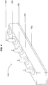
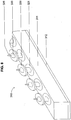
- FIG. 2 illustrates one embodiment of the apparatus 10 of the present invention.
- the apparatus includes a main plate 11 and a plurality of projections 20 positioned along the length of the main plate.
- the main plate may be secured to a base plate 12 which, in turn, is secured to the baling and wrapping machine 90, or other location.
- an insulating sleeve 21 which is intended to minimize heat transfer away from the projection and through the main plate.
- the insulating sleeve may also increase energy efficiency in the apparatus such that the projections maintain a desired temperature with greater consistency and with less energy input.
- the main plate as illustrated, may have a generally rectangular, flat shape; however, the main plate is not limited to this dimension and could also be of a different dimensional shape, and include a face that is concave, convex, stepped, or the like.
- the number of projections, as well as their shape and placement on the main plate, may be predetermined according to the dimension of the wrapped baled item and the desired securing level.
- the main plate, placement of projections, and the like can be a "one-size-fits-all" shape such that, for example, the baled item may be shorter than the main plate such that not all of the projections would be used.
- the baled item be generally the same length, or shorter, than the main plate to ensure that the entire length of the baled item is properly wrapped and secured.
- the main plate can be comprised of any combination of projections, such as those disclosed herein, such that the projection may be of any shape as necessary or suitable for a particular application.
- the shape may be generally cylindrical with a rounded tip (for example, FIGS. 3A and 3B ), generally cylindrical with a sharp tip (for example, FIG. 5 ), generally cylindrical with a flattened tip (for example, FIGS. 10B , 11B ), generally triangular, generally rectangular, generally ovular, or any other suitable shape.
- the projections may also include a stopper disc (for example, FIGS. 7A , 7B ).
- the main plate can include several distinct areas of projections to create an intended welding or melting pattern along the length or a portion of the length of the wrapping material.
- the projections may be, along the length of the main plate, clustered into several groups, or alternatively, the projections may be evenly spaced along the length of the main plate (as illustrated throughout the figures herein), or have any other desired configuration.
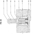
- FIG. 3A illustrates an embodiment of one of the projections 20 positioned along the main plate 11.
- the projection 20 includes an outer projection surface 22, forming a generally cylindrical body with a rounded tip, an inner heating element 23 which can be regulated by a thermostat (not shown, optional), and wiring 24 connecting the heating element with an energy source and the thermostat (if present).
- the wiring may allow for control by a user of whether the heating element of a particular projection is using energy, the amount of energy being used by the specific heating element, control and maintenance of the temperature of the heating element, and the like.
- the projections include a height adjustment mechanism, such as spring 30, such that the height of the projection can be adjustable.
- the spring 30 may allow the projection to adjust between a height, as in FIGS. 2 and 3A , where the projection is extending from the main plate 11 to a position, shown as to certain of the projections in FIG. 14B , where most if not all of the projection is positioned within the main plate. This height may be determined according to the wrapped product shape, the type of wrapping material, the type of baled item, or the like.
- the spring may allow for such uses as allowing for selective contact of the projection to the wrapping material and the baled item, allowing for adjustment of the amount of force the projection applies to the wrapping material and/or baled item, allowing for the uniform application of heat to an uneven surface of the wrapping material and baled item, and the like.
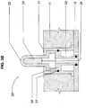
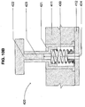
- FIG. 3B Other mechanisms, other than the spring 30, may be used such as, for example, a pressurized air cylinder as illustrated in FIG. 3B , a pressurized oil cylinder, an electronic servo, a command from a computer program, or the like.
- the projection 20' of FIG. 3B includes, rather than a spring, a pressurized air cylinder including a piston 30', a seal element 31' (such as an o-ring) and a volume of pressurized air 32'.
- the outer projection surface 22' and heating element 23' may have an adjustable height, relative to the main plate 11, by movement of the piston 30'.
- the user may regulate the pressure of the pressurized air 32' to determine what height the projection will be positioned and/or the amount of force which would be required to depress the projection 20' from a tallest height, as shown in FIG. 3B , to a lower height.
- the default position of the projections 20' may be in the lowered position, such that they are mostly if not totally within the main plate 11.
- the air pressure may be increased such that the projections rise and extend from the main plate and contact the wrapping material of the wrapped baled item.
- the pressurized air 32' may remain constant such that the projections 20' along the main plate 11 all have a predetermined level of air pressure.
- This alternative may be used, for example, where the wrapped baled item merely rolls over the apparatus 10, such that the piston 30' of each projection 20' allows each projection to adjust its height based on the contour of the surface of the wrapping material.
- the use of the pressurized air cylinder, as with the spring 30 above allows for a uniform application of heat along the width of the wrapping material, such as the tail portion 85, even where the surface of the wrapping material is uneven, as in FIG. 15 .
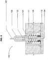
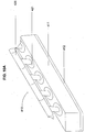
- FIGS. 4 and 5 illustrate another embodiment of the apparatus 110 of the present invention including a main plate 111, base plate 112, an insulating sleeve 121 and at least one projection 120 having a generally cylindrical shape with a sharp tip 125 extending from the rounded end of the outer projection surface 122.
- the projection 120 also includes a heating element 123 and wiring 124.
- a projection including a sharp tip 125 may be used for a variety of applications, and indeed may be preferred in some applications, particularly where, for example, a stronger and more secure welding may be needed. This is due to the combination of welding and perforation by projection 120.
- the sharp tip 125 may allow the projection 120 to puncture through the outside layer of wrapping material, such as the tail portion 85, to directly contact one or more underlying layers, and even optionally the baled item itself, and directly apply heat to each of the punctured layers, the immediate underlying layer not punctured (if any), and even the baled item itself.
- Such penetration welding may in some instances be more robust to provide increased strength to the wrapping material around the baled item.
- the projection 120 may also include a spring 130, though a pressurized air cylinder or other mechanism may be used.
- the combination of the sharp tip 125 with the spring 130 may provide the ability to control the depth that the projection projects into the tail portion, underlying layer or layers, and/or the baled item.
- depth control may be based on the type of wrapping material, the number of layers of material, the weight of the baled item, the type of baled item, the level of desired welding strength, or the like, or any combination thereof.
- the dimensions and properties of the spring such as the compression strength, type of material and the like, may be adjusted to provide a desired height of the projection, a desired penetration depth by the sharp tip 125 into the wrapping material and/or baled item, or the like.
- baled item is soft, like straw, hay or the like, such that the penetration welding would cause minimal if any damage, a projection with a sharp tip may be preferable.
- penetration welding for these types of baled items may also be useful as these soft baled items tend to also be compressible, and thus, may tend to exert a strong outward force on the wrapping material such that added shear may be imparted on the weld, and thus a stronger weld, with higher shear strength, between multiple layers of wrapping material would be beneficial.
- the spring 130 may be used to provide additional benefits to such a baled item, such as to account for any uneven surfaces of the wrapped baled item and to limit the depth of insertion through the wrapping material layers and into the baled item.
- the rounded tip of projection 20 may be used.
- the use of the rounded tip, without the sharp tip 125, may be used where the baled item is particularly flammable and thus direct heat from the projection is not desirable.
- baled items which are easily damaged, particularly from a puncture by the sharp tip may also benefit from the use of projection 20, without a sharp tip.
- an apparatus 210 of the present invention includes a main plate 211, base plate 212, at least one projection 220 and an insulating sleeve 221 between each projection and the main plate.
- Each projection 220 also includes a stopper disc 226 positioned along the length of each projection.
- the stopper disc may, for example, limit movement of the projection into the main plate, or alternatively, limit the ingress of the projection into a depression formed by the projection into the wrapping material (typically where the baled item is particularly soft), or the like.
- FIGS. 7A and 7B illustrate two configurations of projection 220, 220', similar to the projections 20, 20' of FIGS. 3A , 3B , except that both projections 220, 220' have a stopper disc 226, 226'.
- the stopper disc 226, 226' also may include a threaded portion 227, 227' to adjust the height of the stopper disc, and thus, the amount of the outer projection surface 222, 222' extending above the stopper disc 226, 226'.
- the stopper disc may be constructed from any material as desired, though it is preferred that the material have limited thermal conductivity, and thus be similar to the material of the insulating sleeve 221.
- FIGS. 7A and 7B differ between one ( FIG. 7A ) illustrating the use of a spring 230 and the other ( FIG. 7B ) illustrating the use of a pressurized air cylinder 230'.
- FIGS. 7A and 7B differ between one ( FIG. 7A ) illustrating the use of a spring 230 and the other ( FIG. 7B ) illustrating the use of a pressurized air cylinder 230'.
- FIGS. 8 and 9 Illustrated in FIGS. 8 and 9 is a further embodiment of the present invention, similar to the previous embodiments in many respects, though here the apparatus 310 includes a plurality of projections 320 having both a sharp tip 325 and a stopper disc 326. While projection 320 is illustrated as including a spring 330, a different mechanism, such as the pressurized air cylinder, discussed above, may be used instead.
- the stopper disc 326 in combination with the sharp tip 325, may serve to limit penetration of the sharp tip into the tail portion of the wrapping material, one or more underlying layers of material, and/or the baled item. This may be of particular importance and benefit when such a projection 320 is used with a baled item which may be negatively affected by the penetration of the sharp tip into the baled item, but benefits from the sharp tip 325 forming the perforated weld, as discussed above. Moreover, this embodiment may result in a more efficient process because the projection 320 has the benefit of, through perforation welding, directly contacting more layers of wrapping material than just the tail portion of the wrapping material, which results in greater efficiency in that multiple layers are heated and bonded at once. Also, this embodiment may minimize the contact of the sharp tip 325 with the baled item, which typically results in wasted energy and heat, and of course, could also result in damage to the baled item.
- the present invention similar to the previous embodiments in many respects, though here the apparatus 410, 410' has a plurality of projections 420, 420' including a flattened tip 422, 422'.
- the apparatus 410, 410' may be used to create a substantially continuous weld line across the width of the wrapped baled item. Such a continuous weld line may result in a complete, substantially uninterrupted, weld across the width of the wrapped baled item as opposed to the various above embodiments which create concentrated and isolated welds at certain points along the width of the wrapped baled item.
- Such a welding configuration created by apparatus 410, 410' may be suitable for wrapped baled items which do not require an exceptionally strong weld, such as those welds formed by a projection with a sharp tip, and that has a smooth, even contour along the width of the wrapped baled item surface.
- another embodiment of the present invention includes an apparatus 510 having a plurality of projections 520 including a flattened tip 522, and further the projection includes a sharp tip 525 positioned on the flattened tip 522.
- a stopper disc may also be positioned around the sharp tip 525 to limit the penetration of the sharp tip into the wrapped baled item. This embodiment provides a substantially continuous weld line across the width of the wrapped baled item, but provides the added benefit of a stronger weld using the sharp tip 525 to create a perforated weld.
- Such a configuration may be used, for example, for wrapped baled items that have a smooth, even contour along the width of the wrapped baled item surface, and could benefit from a stronger bond on the wrapping material. Also, this embodiment may be used with wrapped baled items where the baled item may not be harmed by the contact of the sharp tip directly on the baled item.
- the present invention also includes various embodiments of methods of using the apparatus to secure a wrapping material around a wrapped baled item. Certain embodiments are illustrated, for example, in FIGS. 1 , 14A , 14B and 15 , utilizing certain embodiments of the apparatus. However, it should be understood that any envisioned embodiments of the apparatus may be used to perform the methods of the present invention and not just those illustrated or described.
- the method includes using the apparatus 10 to secure a wrapping material 80 to a baled item 70.
- an item to be baled and wrapped is placed into a machine, as known in the art, to undergo the baling and wrapping processes, as are known in the art.
- the wrapped baled item is placed onto the apparatus 10, which may be positioned within the chamber of the baling machine 90, as illustrated in FIG. 1 .
- the placement of the wrapped baled item onto the apparatus is predetermined so that the fusing area, for example the tail portion 85 of the wrapping material 80, and the underlying layer or layers, are in contact with the at least one projection 20, 20' of the apparatus 10.
- round baled items 70 which are wrapped with any known wrapped material 80, are usually prepared within a combined baling and wrapping machine 90. Once formed, they are rolled out of the chamber of the baling and wrapping machine directly to the ground or to any temporary station or storage facility.
- the apparatus 10 of the present invention can be positioned to perform the welding step whether the bale rotates direct to the ground or rests temporarily on top of the apparatus.
- a high temperature may be needed in order to weld the tail portion 85 to the underlying layer or layers as the baled item rolls and passes over the apparatus and to the ground.
- the projections including a sharp tip (for example, as in FIGS.
- any welding projection shape e.g., rounded, flattened, or the like
- the temperature of the heating element 23 can be regulated to a constant temperature with or without a control signal (from a thermostat), or the like, such that the apparatus can accommodate a continuous stream of wrapped baled items exiting the baling machine 90.
- the temperature of the heating element 23 may be adjustable or variable as required using a control signal, or the like, from a thermostat or other device. For example, if the time between forming wrapped bales is long, the heating element of the projections may be turned on and off in order to save energy.
- the control signal to turn the heating elements on and off can come from the baling and wrapping machine (through the inclusion of an automated on/off switch, thermostat, thermocouple, or the like), the user (e.g., through manual control using a thermostat), or the like.
- a high temperature, and further a projection having a sharp tip may not be required since the wrapped baled item may be positioned on the apparatus 10 for as long as is necessary to perform the welding process.
- a projection including a pressurized air cylinder may be used to move the projections into and out of a welding position.
- the welding projections can be extended from the main plate and into contact with the wrapping material 80 (and specifically the tail portion 85) of a wrapped baled item for a certain period of time.
- projections including springs may be used.
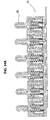
- the projections can accommodate uneven surfaces of the baled item and still apply the appropriate amount of pressure to the wrapping material and/or baled item to perform the welding process, as is illustrated, for example, in FIGS. 14B and 15 .
- the welding projections can be moved by an individual integrated cylinder, in each projection as illustrated, which can activate any welding projection up and down.
- an important aspect of correctly operating the apparatus includes setting the welding projections to the desired temperature required to weld the tail portion 85 into the underlying layer or layers of the wrapping material 80.
- the temperature can be adjusted according to the period of time during which the wrapped item is positioned atop the apparatus.
- the welding of a plastic film tail to the underlying layer can be achieved by setting the heating element of the projection to a temperature between 50 and 250 degrees Celsius for a period between 0.05 and 60 seconds.
- the range of desired temperature and period of time varies according to the type of the wrapping material used, the geometric shape of the heating projections and/or the main plate, the number of layers to be welded, or the like.
- the projection 120 having a sharp tip 125 is used to weld the tail portion 85, such use of the sharp tip may result in an even stronger weld of the wrapping material 80 around the baled item 70.
- the benefit of using this projection is that the force per given area created by the sharp tip is many times higher than a projection having a flat or rounded tip (as in FIGS. 3A or 10B , for example) due to the contact area of the sharp tip being significantly smaller in proportion to the diameter of the projection body, or alternatively, the flat or rounded tip of other projections used in the present invention.
- the wrapping material 80 has a certain amount of friction against the baled item 70, as well as against adjacent layers of wrapping material, which reduces the force imparted on the weld at the tail portion. However, if the tail is firmly welded it will be able to retain this force even if the number of layers, and thereby the amount of friction, is reduced.
- such a strong weld as may be formed using the projections 120 having sharp tips 125 may be sufficient to counteract such forces associated with the tendency of the wrapped material 80 to expand, the tension created during the wrapping process, the tendency of the baled item 70 to expand, and other such forces.
- the wrapped baled item typically has an uneven outer surface (as in FIGS. 14B and 15 ) and further is typically soft (as in FIG. 1 ) because the agricultural product being baled is typically soft, compactable and has a low density, particularly as to products such as hay or straw, for example.
- unique problems arise when securing the wrapping material around such items.
- the apparatus 10 through the use of independent springs 30, pressurized air cylinders 30' (as illustrated), or the like, may allow for the adjustment of the height of each individual projection 20, 20', thereby enabling the proper welding of an uneven surface of a wrapped baled item, which is typical of many agricultural products and other baled items, and particularly so prior to final welding of the wrapping material surrounding such agricultural products. Allowing for height adjustment of the individual projections allows for welding of sunken or depressed areas of the surface of the wrapping material as well as protruded areas to ensure adequate welding is performed along the width of the wrapped baled item. Such welding of uneven surfaces is illustrated in FIGS. 14B and 15 .
- the height adjustment mechanisms of the projections of the apparatus of the present invention allow for better welding of such baled items which are soft or compressible.
- the height adjustment mechanism allows the projection, having a sharp tip, to move as the wrapped baled item moves on top of the apparatus. This movement of the projection minimizes the puncture depth of the projection, which otherwise would puncture deep into the baled item, while maintaining beneficial contact with the wrapping material. Such movement may provide for a better weld and more efficient welding process.
- allowing a projection, which has a rounded or flattened tip, to retract into the main plate as the baled item moves on top of the apparatus minimizes the compression applied to the portion of the baled item and wrapping material on top of the projection which may result in damage to the soft baled item, an undesirable weld due to the deformation of the wrapping material and the baled item, or the like.
- the stopper discs may provide further assistance in achieving a proper weld of the wrapping material by providing a larger surface area against which the wrapping material rests. For example, as the wrapped baled item positions atop the apparatus, the projections retract towards the main plate, and at a certain point the stopper disc engages the outer layer, or tail portion, of the wrapping material. At this point, the stopper discs may form a larger surface area on which the wrapping material and baled item rests, which may assist in smoothing the wrapping material and providing a more even surface on which to perform the weld.
- the apparatus and methods of the present invention resolve the difficulties of welding two or more layers of wrapping material to one another where the surface against which the welding is to occur, e.g., the baled item, is soft, uneven and provides little counterforce, or an uneven counterforce, against the force of the welding projections contacting the wrapping material.
- the apparatus of the present invention provides for bonding between the tail portion and at least one underlying layer of the wrapping material at a molecular level, and thus provides for a strong bond with little chance of failure, even in the presence of rain, dust, wind or other environmental occurrences.
- Such bonding may be performed, using the apparatus of the present invention, on any type of wrapping material suitable for and capable of thermal melting or bonding through the application of energy such as heat.
- wrapping materials may be polymeric film, netting, breathable films, or the like.
- combination wrapping materials may also be used, such as a breathable film combined with a typical netting, as is known in the art, such that the film forms the weld while the netting provides structural strength to the wrapping material.
- a secondary adhesive, applied to the tail portion, may also be used in conjunction with the present invention, though such adhesive would likely be redundant in light of the strong welding properties of the use of the apparatus of the present invention.
Landscapes
- Engineering & Computer Science (AREA)
- Mechanical Engineering (AREA)
- Life Sciences & Earth Sciences (AREA)
- Environmental Sciences (AREA)
- Storage Of Harvested Produce (AREA)
- Basic Packing Technique (AREA)
- Auxiliary Apparatuses For Manual Packaging Operations (AREA)
- Auxiliary Devices For And Details Of Packaging Control (AREA)
Claims (11)
- Vorrichtung (10, 110) zur Sicherung eines Umhüllungsmaterials um einen Gegenstand (70) in Ballenform, wobei die Vorrichtung Folgendes aufweist:eine Hauptplatte (11, 111), undmehrere Vorsprünge (20, 120), die entlang einer Länge der Hauptplatte (11, 111) positioniert sind und sich von der Hauptplatte aus erstrecken, wobei jeder der mehreren Vorsprünge (20, 120) ein Heizelement (23, 123) aufweist, dadurch gekennzeichnet, dass jeder der mehreren Vorsprünge (20, 120) aufweist einen unabhängigen Höheneinstellmechanismus (30, 130, 30, 31', 32', 230'), wobei der Höheneinstellmechanismus für einen vorgegebenen Vorsprung (20, 120) eine durch den Vorsprung (20, 120) das Umhüllungsmaterial beaufschlagende Kraft steuert und eine Kraft zum Bewegen des Vorsprung (20, 120) bereitstellt.
- Vorrichtung (10) nach Anspruch 1, wobei der unabhängige Höheneinstellmechanismus eine Feder (30, 130) oder ein Druckluftzylinder (30', 31', 32', 230') ist.
- Vorrichtung (10) nach Anspruch 2, wobei der Druckluftzylinder einen Kolben (30') aufweist, der für ein Einstellen der Höhe des Vorsprungs im Verhältnis zur Hauptplatte (11) angepasst ist.
- Vorrichtung (10) nach Anspruch 1, wobei der Vorsprung ferner eine scharfe Spitze (125, 325) aufweist.
- Vorrichtung (10) nach Anspruch 4, wobei der Höheneinstellmechanismus auf solche Weise fähig zum Einstellen einer das Umhüllungsmaterial durch die scharfe Spitze (125, 325) beaufschlagenden Kraft ist, dass der unabhängige Höheneinstellmechanismus fähig ist, die Tiefe der Penetration des Vorsprungs in das Umhüllungsmaterial, den Gegenstand oder beide einzustellen.
- Vorrichtung (10) nach Anspruch 1, wobei der Vorsprung (220, 220', 320) ferner eine Anschlagscheibe (226, 226', 326) aufweist.
- Vorrichtung (10) nach Anspruch 6, wobei die Anschlagscheibe (226, 226', 326) aus einem eine begrenzte thermische Leitfähigkeit aufweisendem Material aufgebaut ist.
- Vorrichtung (10) nach Anspruch 6, wobei die Anschlagscheibe (226, 226', 326) einen beweglichen Eingriff mit dem Vorsprung (220, 220', 320) aufweist, der für ein Einstellen der Höhe der Anschlagscheibe im Verhältnis zur Höhe des Vorsprungs angepasst ist.
- Vorrichtung (10) nach Anspruch 1, wobei die Länge der Hauptplatte (11) im Wesentlichen gleich wie oder größer als eine Breite des Umhüllungsmaterials ist.
- Vorrichtung (10) nach Anspruch 1, wobei jeder der mehreren Vorsprünge (20, 120) eine Vorgabeposition hat, in der der Vorsprung wenigstens meistenteils innerhalb der Hauptplatte (11, 111) liegt und wobei der unabhängige Höheneinstellmechanismus für einen vorgegebenen Vorsprung eine Kraft zum Ausdehnen des Vorsprungs von der Hauptplatte (11, 111) in Richtung zum Gegenstand.
- Vorrichtung (10) nach Anspruch 1, wobei die Vorrichtung so konfiguriert ist, dass der Gegenstand auf die Oberseite und über die Vorrichtung reicht.
Applications Claiming Priority (2)
| Application Number | Priority Date | Filing Date | Title |
|---|---|---|---|
| US13/734,428 US9745087B2 (en) | 2013-01-04 | 2013-01-04 | Method and apparatus for securing baled items |
| PCT/IL2013/050319 WO2014106835A1 (en) | 2013-01-04 | 2013-04-11 | Method and apparatus for securing baled items |
Publications (2)
| Publication Number | Publication Date |
|---|---|
| EP2941386A1 EP2941386A1 (de) | 2015-11-11 |
| EP2941386B1 true EP2941386B1 (de) | 2017-09-06 |
Family
ID=48464049
Family Applications (1)
| Application Number | Title | Priority Date | Filing Date |
|---|---|---|---|
| EP13723562.8A Not-in-force EP2941386B1 (de) | 2013-01-04 | 2013-04-11 | Verfahren und vorrichtung zur sicherung von gegenständen in ballenform |
Country Status (8)
| Country | Link |
|---|---|
| US (1) | US9745087B2 (de) |
| EP (1) | EP2941386B1 (de) |
| CN (1) | CN104995093B (de) |
| AR (1) | AR091277A1 (de) |
| AU (1) | AU2013371867B2 (de) |
| BR (1) | BR112015015878B1 (de) |
| WO (1) | WO2014106835A1 (de) |
| ZA (1) | ZA201504745B (de) |
Families Citing this family (5)
| Publication number | Priority date | Publication date | Assignee | Title |
|---|---|---|---|---|
| US20170359960A1 (en) * | 2016-06-15 | 2017-12-21 | Forage Innovations B.V. | Method and system for method for providing a bale of crop material |
| CN106081267B (zh) * | 2016-08-05 | 2019-06-04 | 红云红河烟草(集团)有限责任公司 | 一种包装机封签成型装置的改进结构 |
| AR121711A1 (es) * | 2020-03-31 | 2022-06-29 | Tama group | Envoltura de fardo multicapa |
| CN113044270B (zh) * | 2021-03-03 | 2023-09-22 | 威海华友节能科技有限公司 | 一种自动调节打包层数的打包机 |
| CN115402600B (zh) * | 2022-09-29 | 2024-03-08 | 酒泉钢铁(集团)有限责任公司 | 一种精密仪器安全运输用打包方法 |
Family Cites Families (84)
| Publication number | Priority date | Publication date | Assignee | Title |
|---|---|---|---|---|
| US2322298A (en) * | 1941-02-28 | 1943-06-22 | Mercantile Commerce Bank And T | Thermal attaching machine |
| US2545243A (en) * | 1948-07-10 | 1951-03-13 | Jr Herbert Rumsey | Package encased in plastic sheet material and method of making the same |
| US2915413A (en) | 1955-06-13 | 1959-12-01 | United Biscuit Company Of Amer | Non-blocking adhesive sheet |
| US3044532A (en) * | 1960-03-30 | 1962-07-17 | Vita Mayer & Co Inc | Tail sealing machine |
| NL295480A (de) * | 1962-07-28 | |||
| GB971578A (en) * | 1962-10-02 | 1964-09-30 | Forgrove Mach | Improvements in wrapping machinery |
| US3325331A (en) * | 1963-07-25 | 1967-06-13 | Kalle Ag | Method for welding synthetic plastic films |
| US3447676A (en) * | 1968-01-25 | 1969-06-03 | Corning Glass Works | Tubular package with meltpierced seal |
| US3874146A (en) * | 1971-08-05 | 1975-04-01 | Permtek | Packaging apparatus |
| US3942298A (en) * | 1972-02-21 | 1976-03-09 | August Matzinger | Method of and apparatus for packaging an annular object |
| US3912575A (en) * | 1972-07-05 | 1975-10-14 | Weldotron Corp | Heat sealing apparatus using a wire sealing element |
| US4084999A (en) * | 1973-01-29 | 1978-04-18 | Crown Zellerbach Corporation | Apparatus for forming containers with fin-type seams |
| US3868291A (en) * | 1973-02-16 | 1975-02-25 | Gottlieb Benz | Welding tool for forming synthetic-resin packages |
| US4050221A (en) * | 1973-04-04 | 1977-09-27 | Lantech, Inc. | Stretch-wrapped package, process and apparatus |
| US3867806A (en) * | 1973-04-04 | 1975-02-25 | Lantech Inc | Process of making a stretched-wrapped package |
| CA997260A (en) * | 1973-12-13 | 1976-09-21 | Du Pont Of Canada Limited | Tube forming apparatus and process |
| US3935057A (en) * | 1974-08-28 | 1976-01-27 | Scott Paper Company | Apparatus for securing the free end of a roll of fibrous web material |
| US3996403A (en) * | 1974-11-25 | 1976-12-07 | Signode Corporation | Strapping joint and method and apparatus for forming same |
| ZA756269B (en) * | 1975-10-02 | 1977-04-27 | Singer Alec | Wrapping apparatus and method |
| US4102111A (en) * | 1976-06-01 | 1978-07-25 | Fmc Corporation | Wrapping machine |
| US4062718A (en) * | 1976-09-02 | 1977-12-13 | The Dow Chemical Company | Heat sealing means |
| US4070513A (en) * | 1976-09-20 | 1978-01-24 | Owens-Illinois, Inc. | Heat seal apparatus and seamed sleeve article made thereby |
| SE407677B (sv) * | 1976-10-18 | 1979-04-09 | Gustavsson Olov Erland | Sett och apparat for att forma ett skyddande holje kring ett prismatiskt eller cylindriskt foremal |
| AU520821B2 (en) * | 1977-10-10 | 1982-03-04 | Gerrard Wire Tying Machines Co. | Article strapping |
| US4214029A (en) | 1978-10-30 | 1980-07-22 | Champion International Corporation | Packaging laminate |
| US4218863A (en) * | 1978-11-22 | 1980-08-26 | American Can Company | Continuous motion wrapping machine |
| US4380484A (en) * | 1981-02-20 | 1983-04-19 | William C. Heller, Jr. | Inductively heated tooling and method for working plastic members |
| US4484679A (en) * | 1981-12-16 | 1984-11-27 | Teepak, Inc. | Packaged sheathed tubular strands and method and apparatus for making same |
| US4473432A (en) | 1983-02-04 | 1984-09-25 | Harold Leader | Dot heat stapling |
| US4565728A (en) | 1983-02-04 | 1986-01-21 | Seam Team, Inc. | System and method for application of internal heating to thermally responsive structures |
| US4551965A (en) * | 1983-04-06 | 1985-11-12 | Doboy Verpackungsmaschinen Gmbh | Welding and separating apparatus for plastic films |
| US4490962A (en) * | 1983-08-11 | 1985-01-01 | Crown Zellerbach Corporation | Plastic film wrapper and sealer apparatus |
| US4555296A (en) * | 1984-11-08 | 1985-11-26 | Owens-Illinois, Inc. | Universal hot air nozzle and seal bar with adjustable cam |
| US4651500A (en) * | 1985-02-14 | 1987-03-24 | Valley Tissue Packaging, Inc. | Method and apparatus for wrapping rolls of paper |
| WO1988009748A1 (fr) * | 1987-06-10 | 1988-12-15 | Autefa Maschinenfabrik Gmbh | Procede et dispositif d'emballage de balles comprimees |
| FI82010C (fi) * | 1988-11-30 | 1991-01-10 | Pesmel Insinoeoeritoimisto | Anordningskombination i en foerpackningsmaskin. |
| US5067612A (en) * | 1989-01-26 | 1991-11-26 | Honshu Sangyou Kabushiki Kaisha | Shrink film package having perforated folded strip |
| US5203137A (en) * | 1989-03-08 | 1993-04-20 | Heisei Polymer Co., Ltd. | Annular article-wrapping member and method of making same |
| US5058361A (en) * | 1990-03-14 | 1991-10-22 | Schmacher Roland W | Package end fold sealer and method |
| US5131213A (en) * | 1991-03-06 | 1992-07-21 | Shanklin Corporation | Sealing jaws |
| IT1253297B (it) * | 1991-10-31 | 1995-07-14 | Wrapmatic Spa | Dispositivo allentatore di film applacabile su saldatori di pacchi di rotoli |
| US5226269A (en) * | 1992-05-22 | 1993-07-13 | Haybuster Manufacturing Inc. | Apparatus and method for automatically baling loose fibrous material |
| US5505037A (en) * | 1992-06-29 | 1996-04-09 | Pacmac, Inc. | Vertical form, fill and seal machine for making recloseable bags |
| IT1259797B (it) * | 1992-11-12 | 1996-03-26 | Gruppo di saldatura di film plastico utilizzato per l'avvolgimento di gruppi di prodotti pallettizzati. | |
| US5462807A (en) | 1993-08-20 | 1995-10-31 | Exxon Chemical Patents Inc. | Heat sealable films and articles |
| DE4405120A1 (de) * | 1994-02-17 | 1995-08-31 | Autefa Maschinenfabrik Gmbh Au | Verfahren und Vorrichtung zum Verpacken von Preßballen sowie Packmittelzuschnitt |
| US5598690A (en) * | 1995-08-07 | 1997-02-04 | New Holland North America, Inc. | Tailgate latching apparatus for a round baler |
| US5694738A (en) * | 1996-07-22 | 1997-12-09 | Tokyo Automatic Machinery Works, Ltd. | Body flap folding apparatus in packaging machine |
| US5791125A (en) * | 1997-06-17 | 1998-08-11 | Illinois Tool Works, Inc. | Rotary heat sealer and method therefor |
| US6230473B1 (en) * | 1997-07-04 | 2001-05-15 | Ferag Verpakkingstechniek B.V. | Method and apparatus for packing stacks of flat articles |
| IES980029A2 (en) | 1997-07-25 | 1998-10-07 | Comtor Limited | A combined compacting and wrapping machine |
| JP3830297B2 (ja) * | 1998-06-16 | 2006-10-04 | 株式会社東京自働機械製作所 | 縦形製袋充填包装機の縦シール装置 |
| US6162314A (en) * | 1998-09-29 | 2000-12-19 | Alliant Techsystems Inc. | Thermal welding of fiber reinforced thermoplastic prepreg |
| US6138442A (en) * | 1998-10-13 | 2000-10-31 | Kliklok Corporation | Packaging machine with continuous sealing jaw movement |
| US6038839A (en) * | 1998-11-06 | 2000-03-21 | Triangle Package Machinery Company | Longitudinal seam sealer for polyethylene material |
| DE19916003A1 (de) * | 1999-04-09 | 2000-10-12 | Rovema Gmbh | Vorrichtung zum Verpacken |
| US6565969B1 (en) | 1999-10-21 | 2003-05-20 | 3M Innovative Properties Company | Adhesive article |
| FI108857B (fi) * | 2000-03-22 | 2002-04-15 | Haloila M Oy Ab | Kalvonkäsittelylaite ja käärintälaite |
| US6550229B2 (en) * | 2001-01-12 | 2003-04-22 | Sealed Air Corporation (Us) | Device for sealing two plies of film together, particularly for enclosing a foamable composition in a flexible container |
| ITBO20020463A1 (it) * | 2002-07-18 | 2004-01-19 | Awax Progettazione | Apparato per la termosaldatura continua ed a tenuta dei lembi longitudinali e sovrapposti di elementi tubolari di film termoplastico di spes |
| US6838186B2 (en) | 2002-04-22 | 2005-01-04 | Polinas Plastic Of America, Inc. | Multilayer oriented antimicrobial and antifogging films |
| US7441388B2 (en) * | 2002-04-22 | 2008-10-28 | Restaurant Technology, Inc. | Automated device for packaging food |
| US6960157B2 (en) * | 2002-04-22 | 2005-11-01 | Restaurant Technology, Inc. | Automated system and method for handling food containers |
| US6787209B2 (en) | 2002-12-23 | 2004-09-07 | Tama Plastic Industry | Wrapping material with a Z-lock system and methods of making and using the same |
| US6862867B2 (en) * | 2003-01-16 | 2005-03-08 | Pack-Tech, L.L.C. | Bag sealing system and method |
| TWI328508B (en) * | 2003-07-21 | 2010-08-11 | Ima Spa | An ultrasound unit for sealing lengths of filter paper |
| US7182827B2 (en) * | 2003-07-25 | 2007-02-27 | Kimberly-Clark Worldwide, Inc. | Rotary heat sealing device and method |
| ITBO20030552A1 (it) * | 2003-09-24 | 2005-03-25 | Tissue Machinery Co Spa | Dispositivo per la chiusura delle testate di confezioni ad una sola fila di rotoli in una macchina confezionatrice automatica |
| ITTO20030905A1 (it) * | 2003-11-14 | 2005-05-15 | Opm S P A | Gruppo per il confezionamento di prodotti, in particolare di prodotti alimentari. |
| US7476428B2 (en) | 2004-05-12 | 2009-01-13 | Tetra—Laval Holdings & Finance S.A. | Plastic gas barrier packaging laminate |
| DE602005008681D1 (de) | 2004-09-13 | 2008-09-18 | Ricoh Kk | Wärmeempfindlicher Klebegegenstand |
| SE528619C2 (sv) * | 2005-05-13 | 2006-12-27 | Eco Lean Res & Dev As | Anordning och metod för gasfyllning av en kanal i en förpackning |
| AU2005338771B2 (en) | 2005-11-29 | 2010-09-23 | Tama Plastic Industry | A wrapping material with fastener |
| CN100460202C (zh) | 2006-05-15 | 2009-02-11 | 高学文 | Pvdc-聚烯烃共挤出热成型高阻隔复合包装材料 |
| US7610737B2 (en) * | 2006-08-22 | 2009-11-03 | Valley Tissue Packaging, Inc. | Continuous motion wrapping method |
| JP5305595B2 (ja) | 2007-01-10 | 2013-10-02 | 日東電工株式会社 | 熱接着シート |
| US8567159B2 (en) * | 2007-04-12 | 2013-10-29 | Sealed Air Corporation (Us) | Apparatus and method for making inflated articles |
| US20090044496A1 (en) * | 2007-08-16 | 2009-02-19 | Botelho John W | Method and apparatus for sealing a glass package |
| US7591628B2 (en) * | 2007-10-30 | 2009-09-22 | Deere & Company | Handling and orienting cotton modules wrapped with material including RFID tag |
| ITMI20080392A1 (it) * | 2008-03-10 | 2009-09-11 | Sitma Spa | Gruppo confezionatore ad alta velocita' e macchina confezionatrice dotata di tale gruppo |
| US8512851B2 (en) | 2008-05-01 | 2013-08-20 | Tama Plastic Industry | Wrapping material with opposing adhesive means |
| GB2461544B (en) * | 2008-07-03 | 2012-12-05 | Protomed Ltd | A heat sealing machine for a packaging system |
| US8071196B2 (en) | 2009-03-17 | 2011-12-06 | Deere & Company | Reusable wrapping material for a cylindrical cotton module |
| US10001495B2 (en) | 2012-07-25 | 2018-06-19 | Bioverativ Therapeutics Inc. | Blood factor monitoring assay and uses thereof |
-
2013
- 2013-01-04 US US13/734,428 patent/US9745087B2/en active Active
- 2013-04-11 AU AU2013371867A patent/AU2013371867B2/en active Active
- 2013-04-11 WO PCT/IL2013/050319 patent/WO2014106835A1/en not_active Ceased
- 2013-04-11 CN CN201380073021.XA patent/CN104995093B/zh active Active
- 2013-04-11 EP EP13723562.8A patent/EP2941386B1/de not_active Not-in-force
- 2013-04-11 BR BR112015015878-1A patent/BR112015015878B1/pt active IP Right Grant
- 2013-06-05 AR ARP130101985 patent/AR091277A1/es active IP Right Grant
-
2015
- 2015-07-01 ZA ZA2015/04745A patent/ZA201504745B/en unknown
Non-Patent Citations (1)
| Title |
|---|
| None * |
Also Published As
| Publication number | Publication date |
|---|---|
| BR112015015878A2 (pt) | 2017-07-11 |
| ZA201504745B (en) | 2016-07-27 |
| AU2013371867A1 (en) | 2015-07-16 |
| BR112015015878B1 (pt) | 2020-11-10 |
| AR091277A1 (es) | 2015-01-21 |
| WO2014106835A1 (en) | 2014-07-10 |
| CN104995093B (zh) | 2017-12-01 |
| CN104995093A (zh) | 2015-10-21 |
| US9745087B2 (en) | 2017-08-29 |
| AU2013371867B2 (en) | 2017-03-30 |
| EP2941386A1 (de) | 2015-11-11 |
| US20140190127A1 (en) | 2014-07-10 |
Similar Documents
| Publication | Publication Date | Title |
|---|---|---|
| US9745087B2 (en) | Method and apparatus for securing baled items | |
| AU2013242847B2 (en) | Hinged covering for adhesive surface | |
| US7093406B2 (en) | Method for producing a wrapped bale | |
| WO2006028819A3 (en) | Method of initiating automatic feed of base wrapping material | |
| EP0745047B1 (de) | Verfahren und vorrichtung zum verpacken von pressballen sowie packmittelzuschnitt | |
| US9374945B2 (en) | Combined method for compacting material into a bale and wrapping the bale and a combined baler and bale wrapping apparatus | |
| EP3070024A1 (de) | Verbesserter ballengurt | |
| JP4560346B2 (ja) | ロールベーラの包装材巻回装置 | |
| US12610892B2 (en) | Control system for an agricultural baler | |
| US20230126009A1 (en) | Multilayer Bale Wrap | |
| KR20150088474A (ko) | 롤원단 포장장치에서의 포장지 컷팅/접착을 위한 히팅 나이프 | |
| US12392563B2 (en) | Flexible mat with fluid conduit, method of manufacture thereof and apparatus for the manufacture thereof | |
| US20130068381A1 (en) | Sleeve manufacture | |
| US9382684B1 (en) | Meshless blanket for grass seed | |
| WO2018014943A1 (en) | Improvements to baling strip | |
| US20060280562A1 (en) | Method for manufacturing erosion control blankets | |
| JP2007261656A (ja) | 圧縮された被梱包体の梱包方法及び梱包装置 | |
| US20180279559A1 (en) | Wrapping arrangement and round baler with such | |
| WO1998034463A1 (en) | A bale wrapping vehicle | |
| AU2011278540B2 (en) | Apparatus and method for forming and wrapping material | |
| JPH11511416A (ja) | 合成包装用方法及び装置 | |
| JP2004058328A (ja) | 狭巾部材片の接合方法および装置 | |
| CN207201389U (zh) | 一种用于圆捆打捆机的链式皮带 | |
| GB2614888A (en) | Baler | |
| JPS581006B2 (ja) | 空気抜き皮膜パッケ−ジ連続製造装置 |
Legal Events
| Date | Code | Title | Description |
|---|---|---|---|
| PUAI | Public reference made under article 153(3) epc to a published international application that has entered the european phase |
Free format text: ORIGINAL CODE: 0009012 |
|
| 17P | Request for examination filed |
Effective date: 20150728 |
|
| AK | Designated contracting states |
Kind code of ref document: A1 Designated state(s): AL AT BE BG CH CY CZ DE DK EE ES FI FR GB GR HR HU IE IS IT LI LT LU LV MC MK MT NL NO PL PT RO RS SE SI SK SM TR |
|
| AX | Request for extension of the european patent |
Extension state: BA ME |
|
| 17Q | First examination report despatched |
Effective date: 20151118 |
|
| DAX | Request for extension of the european patent (deleted) | ||
| STAA | Information on the status of an ep patent application or granted ep patent |
Free format text: STATUS: EXAMINATION IS IN PROGRESS |
|
| GRAP | Despatch of communication of intention to grant a patent |
Free format text: ORIGINAL CODE: EPIDOSNIGR1 |
|
| STAA | Information on the status of an ep patent application or granted ep patent |
Free format text: STATUS: GRANT OF PATENT IS INTENDED |
|
| RIC1 | Information provided on ipc code assigned before grant |
Ipc: A01F 15/07 20060101ALI20170124BHEP Ipc: B65B 13/32 20060101ALI20170124BHEP Ipc: B65B 27/12 20060101AFI20170124BHEP |
|
| INTG | Intention to grant announced |
Effective date: 20170215 |
|
| GRAS | Grant fee paid |
Free format text: ORIGINAL CODE: EPIDOSNIGR3 |
|
| GRAJ | Information related to disapproval of communication of intention to grant by the applicant or resumption of examination proceedings by the epo deleted |
Free format text: ORIGINAL CODE: EPIDOSDIGR1 |
|
| GRAL | Information related to payment of fee for publishing/printing deleted |
Free format text: ORIGINAL CODE: EPIDOSDIGR3 |
|
| STAA | Information on the status of an ep patent application or granted ep patent |
Free format text: STATUS: EXAMINATION IS IN PROGRESS |
|
| REG | Reference to a national code |
Ref country code: DE Ref legal event code: R079 Ref document number: 602013026133 Country of ref document: DE Free format text: PREVIOUS MAIN CLASS: B65B0027120000 Ipc: B65B0051120000 |
|
| GRAR | Information related to intention to grant a patent recorded |
Free format text: ORIGINAL CODE: EPIDOSNIGR71 |
|
| STAA | Information on the status of an ep patent application or granted ep patent |
Free format text: STATUS: GRANT OF PATENT IS INTENDED |
|
| INTC | Intention to grant announced (deleted) | ||
| GRAA | (expected) grant |
Free format text: ORIGINAL CODE: 0009210 |
|
| STAA | Information on the status of an ep patent application or granted ep patent |
Free format text: STATUS: THE PATENT HAS BEEN GRANTED |
|
| RIC1 | Information provided on ipc code assigned before grant |
Ipc: B65B 27/12 20060101ALI20170704BHEP Ipc: A01F 15/07 20060101ALI20170704BHEP Ipc: B65B 13/32 20060101ALI20170704BHEP Ipc: B65B 51/12 20060101AFI20170704BHEP |
|
| INTG | Intention to grant announced |
Effective date: 20170727 |
|
| AK | Designated contracting states |
Kind code of ref document: B1 Designated state(s): AL AT BE BG CH CY CZ DE DK EE ES FI FR GB GR HR HU IE IS IT LI LT LU LV MC MK MT NL NO PL PT RO RS SE SI SK SM TR |
|
| REG | Reference to a national code |
Ref country code: GB Ref legal event code: FG4D |
|
| REG | Reference to a national code |
Ref country code: CH Ref legal event code: EP Ref country code: AT Ref legal event code: REF Ref document number: 925602 Country of ref document: AT Kind code of ref document: T Effective date: 20170915 |
|
| REG | Reference to a national code |
Ref country code: IE Ref legal event code: FG4D |
|
| REG | Reference to a national code |
Ref country code: DE Ref legal event code: R096 Ref document number: 602013026133 Country of ref document: DE |
|
| REG | Reference to a national code |
Ref country code: NL Ref legal event code: MP Effective date: 20170906 |
|
| REG | Reference to a national code |
Ref country code: LT Ref legal event code: MG4D |
|
| PG25 | Lapsed in a contracting state [announced via postgrant information from national office to epo] |
Ref country code: FI Free format text: LAPSE BECAUSE OF FAILURE TO SUBMIT A TRANSLATION OF THE DESCRIPTION OR TO PAY THE FEE WITHIN THE PRESCRIBED TIME-LIMIT Effective date: 20170906 Ref country code: HR Free format text: LAPSE BECAUSE OF FAILURE TO SUBMIT A TRANSLATION OF THE DESCRIPTION OR TO PAY THE FEE WITHIN THE PRESCRIBED TIME-LIMIT Effective date: 20170906 Ref country code: LT Free format text: LAPSE BECAUSE OF FAILURE TO SUBMIT A TRANSLATION OF THE DESCRIPTION OR TO PAY THE FEE WITHIN THE PRESCRIBED TIME-LIMIT Effective date: 20170906 Ref country code: SE Free format text: LAPSE BECAUSE OF FAILURE TO SUBMIT A TRANSLATION OF THE DESCRIPTION OR TO PAY THE FEE WITHIN THE PRESCRIBED TIME-LIMIT Effective date: 20170906 Ref country code: NO Free format text: LAPSE BECAUSE OF FAILURE TO SUBMIT A TRANSLATION OF THE DESCRIPTION OR TO PAY THE FEE WITHIN THE PRESCRIBED TIME-LIMIT Effective date: 20171206 |
|
| REG | Reference to a national code |
Ref country code: AT Ref legal event code: MK05 Ref document number: 925602 Country of ref document: AT Kind code of ref document: T Effective date: 20170906 |
|
| PG25 | Lapsed in a contracting state [announced via postgrant information from national office to epo] |
Ref country code: LV Free format text: LAPSE BECAUSE OF FAILURE TO SUBMIT A TRANSLATION OF THE DESCRIPTION OR TO PAY THE FEE WITHIN THE PRESCRIBED TIME-LIMIT Effective date: 20170906 Ref country code: BG Free format text: LAPSE BECAUSE OF FAILURE TO SUBMIT A TRANSLATION OF THE DESCRIPTION OR TO PAY THE FEE WITHIN THE PRESCRIBED TIME-LIMIT Effective date: 20171206 Ref country code: RS Free format text: LAPSE BECAUSE OF FAILURE TO SUBMIT A TRANSLATION OF THE DESCRIPTION OR TO PAY THE FEE WITHIN THE PRESCRIBED TIME-LIMIT Effective date: 20170906 Ref country code: GR Free format text: LAPSE BECAUSE OF FAILURE TO SUBMIT A TRANSLATION OF THE DESCRIPTION OR TO PAY THE FEE WITHIN THE PRESCRIBED TIME-LIMIT Effective date: 20171207 Ref country code: ES Free format text: LAPSE BECAUSE OF FAILURE TO SUBMIT A TRANSLATION OF THE DESCRIPTION OR TO PAY THE FEE WITHIN THE PRESCRIBED TIME-LIMIT Effective date: 20170906 |
|
| PG25 | Lapsed in a contracting state [announced via postgrant information from national office to epo] |
Ref country code: NL Free format text: LAPSE BECAUSE OF FAILURE TO SUBMIT A TRANSLATION OF THE DESCRIPTION OR TO PAY THE FEE WITHIN THE PRESCRIBED TIME-LIMIT Effective date: 20170906 |
|
| PG25 | Lapsed in a contracting state [announced via postgrant information from national office to epo] |
Ref country code: CZ Free format text: LAPSE BECAUSE OF FAILURE TO SUBMIT A TRANSLATION OF THE DESCRIPTION OR TO PAY THE FEE WITHIN THE PRESCRIBED TIME-LIMIT Effective date: 20170906 Ref country code: RO Free format text: LAPSE BECAUSE OF FAILURE TO SUBMIT A TRANSLATION OF THE DESCRIPTION OR TO PAY THE FEE WITHIN THE PRESCRIBED TIME-LIMIT Effective date: 20170906 Ref country code: PL Free format text: LAPSE BECAUSE OF FAILURE TO SUBMIT A TRANSLATION OF THE DESCRIPTION OR TO PAY THE FEE WITHIN THE PRESCRIBED TIME-LIMIT Effective date: 20170906 |
|
| PG25 | Lapsed in a contracting state [announced via postgrant information from national office to epo] |
Ref country code: EE Free format text: LAPSE BECAUSE OF FAILURE TO SUBMIT A TRANSLATION OF THE DESCRIPTION OR TO PAY THE FEE WITHIN THE PRESCRIBED TIME-LIMIT Effective date: 20170906 Ref country code: IS Free format text: LAPSE BECAUSE OF FAILURE TO SUBMIT A TRANSLATION OF THE DESCRIPTION OR TO PAY THE FEE WITHIN THE PRESCRIBED TIME-LIMIT Effective date: 20180106 Ref country code: SM Free format text: LAPSE BECAUSE OF FAILURE TO SUBMIT A TRANSLATION OF THE DESCRIPTION OR TO PAY THE FEE WITHIN THE PRESCRIBED TIME-LIMIT Effective date: 20170906 Ref country code: SK Free format text: LAPSE BECAUSE OF FAILURE TO SUBMIT A TRANSLATION OF THE DESCRIPTION OR TO PAY THE FEE WITHIN THE PRESCRIBED TIME-LIMIT Effective date: 20170906 Ref country code: IT Free format text: LAPSE BECAUSE OF FAILURE TO SUBMIT A TRANSLATION OF THE DESCRIPTION OR TO PAY THE FEE WITHIN THE PRESCRIBED TIME-LIMIT Effective date: 20170906 Ref country code: AT Free format text: LAPSE BECAUSE OF FAILURE TO SUBMIT A TRANSLATION OF THE DESCRIPTION OR TO PAY THE FEE WITHIN THE PRESCRIBED TIME-LIMIT Effective date: 20170906 |
|
| REG | Reference to a national code |
Ref country code: DE Ref legal event code: R097 Ref document number: 602013026133 Country of ref document: DE |
|
| PLBE | No opposition filed within time limit |
Free format text: ORIGINAL CODE: 0009261 |
|
| STAA | Information on the status of an ep patent application or granted ep patent |
Free format text: STATUS: NO OPPOSITION FILED WITHIN TIME LIMIT |
|
| PG25 | Lapsed in a contracting state [announced via postgrant information from national office to epo] |
Ref country code: DK Free format text: LAPSE BECAUSE OF FAILURE TO SUBMIT A TRANSLATION OF THE DESCRIPTION OR TO PAY THE FEE WITHIN THE PRESCRIBED TIME-LIMIT Effective date: 20170906 |
|
| 26N | No opposition filed |
Effective date: 20180607 |
|
| PG25 | Lapsed in a contracting state [announced via postgrant information from national office to epo] |
Ref country code: SI Free format text: LAPSE BECAUSE OF FAILURE TO SUBMIT A TRANSLATION OF THE DESCRIPTION OR TO PAY THE FEE WITHIN THE PRESCRIBED TIME-LIMIT Effective date: 20170906 |
|
| REG | Reference to a national code |
Ref country code: DE Ref legal event code: R119 Ref document number: 602013026133 Country of ref document: DE |
|
| PG25 | Lapsed in a contracting state [announced via postgrant information from national office to epo] |
Ref country code: MC Free format text: LAPSE BECAUSE OF FAILURE TO SUBMIT A TRANSLATION OF THE DESCRIPTION OR TO PAY THE FEE WITHIN THE PRESCRIBED TIME-LIMIT Effective date: 20170906 |
|
| REG | Reference to a national code |
Ref country code: CH Ref legal event code: PL |
|
| REG | Reference to a national code |
Ref country code: BE Ref legal event code: MM Effective date: 20180430 |
|
| GBPC | Gb: european patent ceased through non-payment of renewal fee |
Effective date: 20180411 |
|
| REG | Reference to a national code |
Ref country code: IE Ref legal event code: MM4A |
|
| PG25 | Lapsed in a contracting state [announced via postgrant information from national office to epo] |
Ref country code: LU Free format text: LAPSE BECAUSE OF NON-PAYMENT OF DUE FEES Effective date: 20180411 Ref country code: DE Free format text: LAPSE BECAUSE OF NON-PAYMENT OF DUE FEES Effective date: 20181101 |
|
| PG25 | Lapsed in a contracting state [announced via postgrant information from national office to epo] |
Ref country code: BE Free format text: LAPSE BECAUSE OF NON-PAYMENT OF DUE FEES Effective date: 20180430 Ref country code: GB Free format text: LAPSE BECAUSE OF NON-PAYMENT OF DUE FEES Effective date: 20180411 Ref country code: CH Free format text: LAPSE BECAUSE OF NON-PAYMENT OF DUE FEES Effective date: 20180430 Ref country code: LI Free format text: LAPSE BECAUSE OF NON-PAYMENT OF DUE FEES Effective date: 20180430 |
|
| PG25 | Lapsed in a contracting state [announced via postgrant information from national office to epo] |
Ref country code: IE Free format text: LAPSE BECAUSE OF NON-PAYMENT OF DUE FEES Effective date: 20180411 Ref country code: FR Free format text: LAPSE BECAUSE OF NON-PAYMENT OF DUE FEES Effective date: 20180430 |
|
| PG25 | Lapsed in a contracting state [announced via postgrant information from national office to epo] |
Ref country code: MT Free format text: LAPSE BECAUSE OF NON-PAYMENT OF DUE FEES Effective date: 20180411 |
|
| PG25 | Lapsed in a contracting state [announced via postgrant information from national office to epo] |
Ref country code: PT Free format text: LAPSE BECAUSE OF FAILURE TO SUBMIT A TRANSLATION OF THE DESCRIPTION OR TO PAY THE FEE WITHIN THE PRESCRIBED TIME-LIMIT Effective date: 20170906 |
|
| PG25 | Lapsed in a contracting state [announced via postgrant information from national office to epo] |
Ref country code: HU Free format text: LAPSE BECAUSE OF FAILURE TO SUBMIT A TRANSLATION OF THE DESCRIPTION OR TO PAY THE FEE WITHIN THE PRESCRIBED TIME-LIMIT; INVALID AB INITIO Effective date: 20130411 Ref country code: MK Free format text: LAPSE BECAUSE OF NON-PAYMENT OF DUE FEES Effective date: 20170906 Ref country code: CY Free format text: LAPSE BECAUSE OF FAILURE TO SUBMIT A TRANSLATION OF THE DESCRIPTION OR TO PAY THE FEE WITHIN THE PRESCRIBED TIME-LIMIT Effective date: 20170906 |
|
| PG25 | Lapsed in a contracting state [announced via postgrant information from national office to epo] |
Ref country code: AL Free format text: LAPSE BECAUSE OF FAILURE TO SUBMIT A TRANSLATION OF THE DESCRIPTION OR TO PAY THE FEE WITHIN THE PRESCRIBED TIME-LIMIT Effective date: 20170906 |
|
| P01 | Opt-out of the competence of the unified patent court (upc) registered |
Effective date: 20230530 |
|
| PG25 | Lapsed in a contracting state [announced via postgrant information from national office to epo] |
Ref country code: TR Free format text: LAPSE BECAUSE OF NON-PAYMENT OF DUE FEES Effective date: 20180411 |