EP2940341A1 - Leichtbaustruktur - Google Patents
Leichtbaustruktur Download PDFInfo
- Publication number
- EP2940341A1 EP2940341A1 EP14001532.2A EP14001532A EP2940341A1 EP 2940341 A1 EP2940341 A1 EP 2940341A1 EP 14001532 A EP14001532 A EP 14001532A EP 2940341 A1 EP2940341 A1 EP 2940341A1
- Authority
- EP
- European Patent Office
- Prior art keywords
- vibration
- structure according
- lightweight structure
- lightweight
- absorbing element
- Prior art date
- Legal status (The legal status is an assumption and is not a legal conclusion. Google has not performed a legal analysis and makes no representation as to the accuracy of the status listed.)
- Granted
Links
Images

Classifications
-
- F—MECHANICAL ENGINEERING; LIGHTING; HEATING; WEAPONS; BLASTING
- F16—ENGINEERING ELEMENTS AND UNITS; GENERAL MEASURES FOR PRODUCING AND MAINTAINING EFFECTIVE FUNCTIONING OF MACHINES OR INSTALLATIONS; THERMAL INSULATION IN GENERAL
- F16F—SPRINGS; SHOCK-ABSORBERS; MEANS FOR DAMPING VIBRATION
- F16F1/00—Springs
- F16F1/02—Springs made of steel or other material having low internal friction; Wound, torsion, leaf, cup, ring or the like springs, the material of the spring not being relevant
- F16F1/025—Springs made of steel or other material having low internal friction; Wound, torsion, leaf, cup, ring or the like springs, the material of the spring not being relevant characterised by having a particular shape
-
- F—MECHANICAL ENGINEERING; LIGHTING; HEATING; WEAPONS; BLASTING
- F16—ENGINEERING ELEMENTS AND UNITS; GENERAL MEASURES FOR PRODUCING AND MAINTAINING EFFECTIVE FUNCTIONING OF MACHINES OR INSTALLATIONS; THERMAL INSULATION IN GENERAL
- F16F—SPRINGS; SHOCK-ABSORBERS; MEANS FOR DAMPING VIBRATION
- F16F3/00—Spring units consisting of several springs, e.g. for obtaining a desired spring characteristic
- F16F3/02—Spring units consisting of several springs, e.g. for obtaining a desired spring characteristic with springs made of steel or of other material having low internal friction
Definitions
- Lightweight structures have been known for a long time. An important reason for the use of lightweight structures is the weight reduction of the components equipped with it. Lightweight structures are used, for example, in aircraft construction, in the automotive industry and in the construction industry, in particular in the construction of buildings. Furthermore, lightweight structures are used in medical applications.
- Lightweight structures can be formed in different ways. It is possible that lightweight material is used, i. The lightweight structure and the weight savings result primarily from the material properties.
- the externally excited vibrations include, for example, vibrations caused by earthquakes, while self-excited vibrations can be caused, in particular by bridges, by wind load.
- vibration absorbers for vibration absorption which are adjustable to the vibration frequency to be eliminated, for example of the building or the like, and thereby extract from the structure vibration energy which they use for their own oscillating motions.
- vibration absorbers are designed as Tilgerpendel.
- vibration absorbers have a large mass, a large volume of construction and are expensive to purchase.
- the object of the invention is therefore to provide a lightweight structure, which has an expanded functionality over conventional lightweight structures.
- the lightweight construction according to the invention has at least one structural unit which has a top flange and a bottom flange, between which at least one vibration-absorbing element for vibration absorption or vibration damping is absorbed by acting on the structural unit vibrations.
- a lightweight structure which, in addition to a low weight and high stability, is designed to absorb vibrations as an additional property.
- self-excited or externally excited vibrations can be reduced, as a result of which the components equipped therewith, for example buildings, are less prone to vibration. Since the vibration absorption takes place in the structure of the lightweight structure, additional vibration absorbers, as known from the prior art, can be omitted. This can lead to a cost savings.
- a plurality of structural units are connected to one another to form a spatial framework.
- the structural units can thus be expanded arbitrarily in the three spatial directions.
- the vibration-absorbing element is reversibly deformable. It would be conceivable that the vibration-absorbing element is constructed of components, each of which has no reversible deformability per se, but in the group in the interaction of the various components, a reversible deformability is created. However, it is particularly preferred if the vibration-absorbing element consists of reversibly deformable material.
- the vibration-absorbing elements are connected to each other by means of connection nodes to a branched structure cluster.
- the connection of the vibration-absorbing elements with each other leads to a higher stability of the composite compared to lightweight structures, in which the vibration damping elements are not connected to each other, although this would be possible.
- the vibration-absorbing elements are integrally formed on the connection nodes.
- Such an embodiment could be produced for example by means of generative manufacturing processes.
- branches it is possible for the branches to be wave-shaped. However, other embodiments of the branches are possible.
- the vibration-absorbing element is designed as a single or multiple helix.
- a double helix can be used as the vibration absorbing element.
- the vibration-damping elements in the form of the helices are branched or networked with one another by connecting nodes being formed at locations where the helical lines of adjacent helices touch or approach one another.
- cut elements of the helices which are formed by cuts running along the longitudinal axis, as the vibration-absorbing element.
- helix halves as vibration-absorbing elements, each of which has been created by a section through the central longitudinal axis of a double helix. These helix halves can then in turn be connected via connection nodes to adjacent helix halves.
- the vibration-absorbing element as a single / multiple helix
- a plurality of Möbius loops lying next to one another in each of the three spatial directions are provided, wherein, in particular, adjacent Möbius loops are interconnected at nodal points in all three spatial directions.
- the mutually adjacent Möbiusschleifen can adjoin or abut each other or penetrate at the node or crossing points. It is possible that in each case adjacent Möbiusschleifen have a distance from each other in two of the three spatial direction.
- the two straps and the at least one vibration-absorbing element are formed as a one-piece structure.
- these can form a one-piece structure together with the upper and lower belt.
- the structural cluster is stiffened per se and is included as a separate component between the upper and lower belt, where he is then non-positively and / or positively and / or materially connected to the upper and lower belt.
- the invention further relates to the use of a lightweight structure according to one of claims 1 to 12 as a supporting structure, in particular in buildings.
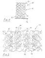
- FIG. 1 shows a first embodiment of the lightweight structure 11 according to the invention.
- An essential element of the lightweight construction structure 11 according to the invention is at least one vibration-absorbing element 15, which is accommodated between upper and lower belt 13, 14 and is designed for vibration absorption of vibrations acting on the structural unit 12.
- a plurality of vibration-absorbing elements 15 are distributed between two Upper and lower belt 13, 14 are arranged.
- the vibration absorbing member 15 is made of reversibly deformable material.
- the double helices may be formed from the material of the upper and lower chords 13, 14, i. the double helices and the two straps 13, 14 form a one-piece structure.
- FIG. 2 shows a second embodiment of the lightweight structure 11 according to the invention.
- the vibration-absorbing elements 15, which are also distributed in a planar manner between the upper and lower belts 13, 14, are networked together in the form of helices.
- the vibration-absorbing elements 15 are connected by means of connection nodes 16 to a branched structure cluster 17.
- the vibration absorbing elements 15 are formed as Doppelhelices as in the first embodiment.
- the double helices are cut along the spacing direction of the two straps 13, 14; in particular, the cuts result in helix halves 18 which are connected to adjacent helix halves 18 at the connection nodes 16.
- the structure of the interconnected helix halves can also be produced as a one-piece structure. It would be for example, it is possible to manufacture the one-piece structure by 3D printing, for example laser sintering or selective laser melting or EBM (Electro Beam Melting).
- 3D printing for example laser sintering or selective laser melting or EBM (Electro Beam Melting).
- the two straps 13, 14 mitanformen equal.
- the two straps 13, 14 may be plate-like, so that a structural unit 12 of top and bottom chord 14 and the structural cluster 17 may be used for example for walls or floors or ceilings of buildings.
- the two straps 13, 14 as a free-form body, which are limited by free-form surfaces produce.
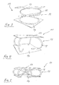
- FIG. 3 shows a third embodiment of the lightweight structure 11 according to the invention.
- FIG. 4 shows a fourth embodiment of the lightweight structure 11 according to the invention also here are between upper and lower flange 13, 14 a plurality of vibration damping elements 15 are provided.
- the vibration-absorbing elements 15 consist of approximately C-shaped profiled bars, which are connected on the one hand to the upper and on the other hand with the lower flange 13, 14.
- FIG. 5 shows a fifth embodiment of the lightweight construction according to the invention.
- the vibration-absorbing elements 15 are formed as Möbiusschleifen.
- the loop halves are each connected on the one hand to the upper and the other with the lower flange 13, 14.
- the two straps 13, 14 and the Möbius loops can be formed as a one-piece structure, for example, produce by means of generative manufacturing process.
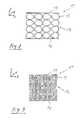
- FIGS. 6 and 7 show a sixth embodiment of the lightweight construction structure 11 according to the invention.
- the vibration-absorbing elements 15 are formed as Möbiusschleifen.
- a plurality of Möbius loops arranged between the upper and lower belts 13, 14 form the structural unit 12 FIG. 6
- the Möbius loops are arranged side by side in the X direction of a Cartesian coordinate system spanned by X, Y and Z coordinates, with mutually adjacent Möbius loops abutting one another at the nodal points. It is also possible that each adjacent Möbiusschleifen penetrate each other at the nodes.
- the Möbius loops are also in the Y direction Row one above the other. Moobius loops adjacent to each other in the Y direction abut each other at the nodal points.
- FIG. 7 shows a 90 ° to the Figure 6 rotated view of the structural cluster 17. It can be seen that the Möbius loops in the Z direction have a relatively small extent and are relatively densely packed in series one behind the other. Here, too, adjacent Möbius loops abut one another at the nodes in the Z direction.
- each Möbius loop of the structural unit 12 is connected in both X- and Y- and Z-direction with Möbius loops adjacent in these directions.
- the crosslinking results in a relatively strong damping effect, since the degree of damping, in addition to the material properties of the Möbius loops, is also determined by the connection of the Möbius loops to one another at the nodal points.
- the distribution of the vibrations acting on the lightweight structure is possible in all three spatial directions, whereby an improved vibration absorption can be achieved.
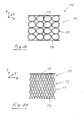
- FIGS. 8 and 9 show a seventh embodiment of the lightweight construction structure 11 according to the invention.
- This embodiment differs from the previously described embodiment in that in each case adjacent Möbiusschleifen both in the X and in the Z direction ( FIG. 9 ) are arranged at a distance from each other. This results between the upper and lower chords 13, 14 extending Möbiusschleifen columns.
- a structural unit 12 has a weaker damping, since here the degree of damping is essentially influenced by the material properties of the Möbius loops.
- FIGS. 10 and 11 an eighth embodiment of the lightweight construction structure 11 according to the invention in this embodiment of the networking in the three spatial directions in the FIGS. 6 and 7 corresponds, the vibration damping elements 15 are designed differently.
- the resulting structure is further distinguished by the fact that it has a relatively large extent in the Z direction. This is achieved in that the two annular structures do not form a common plane, but the one circular structure inclined in one direction and the other circular structure is inclined in the opposite direction.
- the structural unit is less densely packed compared to the structural unit of the sixth embodiment.
Landscapes
- Engineering & Computer Science (AREA)
- General Engineering & Computer Science (AREA)
- Mechanical Engineering (AREA)
- Building Environments (AREA)
- Vibration Prevention Devices (AREA)
Abstract
Description
- Die Erfindung betrifft eine Leichtbaustruktur.
- Leichtbaustrukturen sind bereits seit langem bekannt. Ein wichtiger Grund für den Einsatz von Leichtbaustrukturen ist die Gewichtsreduktion der damit ausgestatteten Bauteile. Leichtbaustrukturen finden beispielsweise Anwendung im Flugzeugbau, in der Automobilindustrie und in der Bauindustrie, insbesondere beim Bau von Gebäuden. Ferner werden Leichtbaustrukturen in medizinischen Anwendungen verwendet.
- Leichtbaustrukturen können auf unterschiedliche Arten gebildet werden. Es ist möglich, dass Leichtbaumaterial eingesetzt wird, d.h. die Leichtbaustruktur und die Gewichtsersparnis resultieren in erster Linie aus den Materialeigenschaften.
- Ein anderer Ansatz ist, die Leichtbaustruktur dadurch zu bilden, dass herkömmlich verwendetes Material mit Material-Ausmagerungen versehen ist, so dass das durch die Material-Ausmagerungen eingesparte Material eine Gewichtsreduktion ergibt.
- Schließlich ist noch ein weiterer Ansatz denkbar, nämlich dass die Leichtbaustruktur aus miteinander zu einem Fachwerk verbundenen Stützstäben ausgebildet ist. Allen Leichtbaustrukturen ist jedoch gemeinsam, dass die Gewichtsreduktion nicht zu Lasten der Stabilität des gesamten Systems gehen darf.
- Beim Bau von Gebäuden, Brücken oder dergleichen besteht der Bedarf, die Bauten gegen selbst- und fremderregte Schwingungen zu sichern. Zu den fremderregten Schwingungen gehören beispielsweise durch Erdbeben verursachte Schwingungen, während selbsterregte Schwingungen insbesondere bei Brücken durch Windlast verursacht werden können. Es ist bereits bekannt, zur Schwingungsabsorption sogenannte Schwingungstilger einzusetzen, die auf die zu eliminierende Schwingfrequenz, beispielsweise des Gebäudes oder dergleichen, einstellbar sind und dadurch der Struktur Schwingungsenergie entziehen, die sie für ihre eigenen Schwingbewegungen nutzen. In der Regel sind solche Schwingungstilger als Tilgerpendel ausgebildet.
- Derartige Schwingungstilger haben jedoch eine große Masse, ein großes Bauvolumen und sind kostenintensiv in der Anschaffung.
- Aufgabe der Erfindung ist es daher, eine Leichtbaustruktur bereitzustellen, die gegenüber herkömmlichen Leichtbaustrukturen eine erweiterte Funktionalität besitzt.
- Diese Aufgabe wird durch eine Leichtbaustruktur mit den Merkmalen des unabhängigen Anspruchs 1 gelöst. Weiterbildungen der Erfindung sind in den Unteransprüchen dargestellt.
- Die erfindungsgemäße Leichtbaustruktur besitzt wenigstens eine Struktureinheit, die einen Obergurt und einen Untergurt aufweist, zwischen denen wenigstens ein schwingungsabsorbierendes Element zur Schwingungsabsorption bzw. Schwingungsdämpfung von auf die Struktureinheit einwirkenden Schwingungen aufgenommen ist.
- Es wird also eine Leichtbaustruktur geschaffen, die neben einem geringen Gewicht und hoher Stabilität noch als zusätzliche Eigenschaft schwingungsabsorbierend ausgebildet ist. Mit der Leichtbaustruktur lassen sich selbst- oder fremderregte Schwingungen abbauen, wodurch die damit ausgestatteten Bauteile, beispielsweise Gebäude, weniger schwingungsanfällig sind. Da die Schwingungsabsorption in der Struktur der Leichtbaustruktur stattfindet, können zusätzliche Schwingungstilger, wie aus dem Stand der Technik bekannt, entfallen. Dies kann zu einer Kostenersparnis führen.
- Bei einer Weiterbildung der Erfindung sind mehrere Struktureinheiten miteinander zu einem Raumfachwerk verbunden. Die Struktureinheiten lassen sich also beliebig in den drei Raumrichtungen erweitern.
- In besonders bevorzugter Weise ist das schwingungsabsorbierende Element reversibel verformbar. Es wäre denkbar, dass das schwingungsabsorbierende Element aus Komponenten aufgebaut ist, die jede für sich keine reversible Verformbarkeit besitzt, jedoch in der Gruppe beim Zusammenwirken der verschiedenen Komponenten eine reversible Verformbarkeit geschaffen wird. Besonders bevorzugt ist es jedoch, wenn das schwingungsabsorbierende Element aus reversibel verformbarem Material besteht.
- In besonders bevorzugter Weise sind die schwingungsabsorbierenden Elemente untereinander mittels Verbindungsknoten zu einem verästelten Strukturcluster verbunden. Die Verbindung der schwingungsabsorbierenden Elemente untereinander führt zu einer höher Stabilität des Verbundes im Vergleich zu Leichtbaustrukturen, bei denen die schwingungsdämpfenden Elemente untereinander nicht verbunden sind, wenngleich dies auch möglich wäre. Es wäre beispielsweise möglich, dass die schwingungsabsorbierenden Elemente an den Verbindungsknoten aneinander angeformt sind. Eine solche Ausgestaltung könnte beispielsweise mittels generativer Fertigungsverfahren hergestellt werden.
- Es ist beispielsweise möglich, dass die Verästelungen wellenartig ausgebildet sind. Es sind jedoch auch andere Ausgestaltungen der Verästelungen möglich.
- Bei einer Weiterbildung der Erfindung ist das schwingungsabsorbierende Element in der Abstandsrichtung der beiden Gurte federelastisch nachgiebig ausgebildet.
- In besonders bevorzugter Weise ist das schwingungsabsorbierende Element als Einfach-/oder Mehrfachhelix ausgebildet. Es kann beispielsweise eine Doppelhelix als schwingungsabsorbierendes Element verwendet werden. In besonders bevorzugter Weise sind die schwingungsdämpfenden Elemente in Form der Helices dadurch miteinander verästelt bzw. vernetzt, dass an Stellen an denen sich die Schraubenlinien benachbarter Helices berühren oder einander nahekommen, Verbindungsknoten ausgebildet sind. Es ist möglich, dass als schwingungsabsorbierendes Element Schnittkörper der Helices verwendet werden, die durch entlang der Längsachse verlaufende Schnitte gebildet sind. Es ist beispielsweise möglich, als schwingungsabsorbierende Elemente jeweils Helixhälften zu verwenden, die jeweils durch einen Schnitt durch die Mittel-Längsachse einer Doppelhelix entstanden sind. Diese Helixhälften können dann wiederum über Verbindungsknoten mit benachbarten Helixhälften verbunden sein.
- Alternativ zur Ausgestaltung des schwingungsabsorbierenden Elementes als Einfach-/und Mehrfachhelix, ist es jedoch auch denkbar, das schwingungsabsorbierende Element als Möbiusschleife auszubilden. Es können mehrere insbesondere ineinander verschlungene Möbiusschleifen als Struktureinheit eingesetzt werden. Ferner ist es möglich, dass mehrere jeweils in den drei Raumrichtungen nebeneinander liegende Möbiusschleifen vorgesehen sind, wobei insbesondere jeweils in allen drei Raumrichtungen benachbarte Möbiusschleifen an Knotenpunkten miteinander verbunden sind. Die einander benachbarten Möbiusschleifen können aneinander angrenzen bzw. anstoßen oder sich an den Knoten- oder Kreuzungspunkten durchdringen. Es ist möglich, dass jeweils einander benachbarte Möbiusschleifen in zwei der drei Raumrichtung einen Abstand zueinander aufweisen.
- In besonders bevorzugter Weise sind die beiden Gurte und das wenigstens eine schwingungsabsorbierende Element als einstückige Struktur ausgebildet. Bei einer Vielzahl flächig verteilter schwingungsabsorbierenden Elementen können diese zusammen mit dem Ober- und Untergurt eine einstückige Struktur bilden. Alternativ wäre es jedoch auch denkbar, dass vor allem im Falle von flächig verteilten schwingungsabsorbierenden Elementen, die miteinander über Verbindungsknoten verästelt sind und dadurch einen Strukturcluster bilden, der Strukturcluster an sich ausgesteift ist und als separate Komponente zwischen dem Ober- und Untergurt aufgenommen ist, wo er dann kraft- und/oder formschlüssig und/oder stoffschlüssig mit Ober- und Untergurt verbunden ist.
- Es ist möglich, dass das schwingungsabsorbierende Element als Festkörperschaum ausgebildet ist. Zweckmäßigerweise besteht der Festkörperschaum aus Schaumstoff. Es kann offenzelliger oder geschlossenzelliger Schaumstoff verwendet werden.
- Die Erfindung betrifft ferner noch die Verwendung einer Leichtbaustruktur gemäß einem der Ansprüche 1 bis 12 als Tragwerkstruktur, insbesondere in Gebäuden.
- Bevorzugte Ausführungsbeispiele der Erfindung sind in der Zeichnung dargestellt und werden im Folgenden näher erläutert. Die Zeichnungen zeigen:
- Figur 1
- einen Schnitt durch ein erstes Ausführungsbeispiel der erfindungsgemäßen Leichtbaustruktur,
- Figur 2
- eine perspektivische Darstellung eines zweiten Ausführungsbeispiels der erfindungsgemäßen Leichtbaustruktur,
- Figur 3
- eine perspektivische Darstellung eines dritten Ausführungsbeispiels der erfindungsgemäßen Leichtbaustruktur,
- Figur 4
- eine perspektivische Darstellung eines vierten Ausführungsbeispiels der erfindungsgemäßen Leichtbaustruktur,
- Figur 5
- eine perspektivische Darstellung eines fünften Ausführungsbeispiels der erfindungsgemäßen Leichtbaustruktur,
- Figur 6
- einen Schnitt durch ein sechstes Ausführungsbeispiel der erfindungsgemäßen Leichtbaustruktur,
- Figur 7
- eine gegenüber
Fig. 6 um 90° gedrehte Ansicht der Leichtbaustruktur vonFig.6 , - Figur 8
- einen Schnitt durch ein siebtes Ausführungsbeispiel der erfindungsgemäßen Leichtbaustruktur,
- Figur 9
- eine gegenüber
Fig. 8 um 90° gedrehte Ansicht der Leichtbaustruktur vonFig.8 , - Figur 10
- einen Schnitt durch ein achtes Ausführungsbeispiel der erfindungsgemäßen Leichtbaustruktur,
- Figur 11
- eine gegenüber
Fig. 10 um 90° gedrehte Ansicht der Leichtbaustruktur vonFig.10 , - Die
Figur 1 zeigt ein erstes Ausführungsbeispiel der erfindungsgemäßen Leichtbaustruktur 11. - Die Struktureinheit 12 besitzt einen Obergurt 13 und einen in einer Abstandsrichtung mit Abstand zum Obergurt 13 angeordneten Untergurt 14. Ober- und Untergurt 13, 14 sind beispielhaft plattenartig dargestellt, sie können jedoch auch eine beliebig andere Form aufweisen, beispielsweise können Ober- und/oder Untergurt von Freiformflächen begrenzt sein. Auch die Dicke bzw. Stärke des Ober- und Untergurts ist jeweils beliebig wählbar, jedoch versteht es sich von selbst, dass bei einer Leichtbaustruktur Ober- und Untergurte mit relativ geringen Wandstärken eingesetzt sind.
- Ein wesentliches Element der erfindungsgemäßen Leichtbaustruktur 11 ist wenigstens ein schwingungsabsorbierendes Element 15, das zwischen Ober- und Untergurt 13, 14 aufgenommen ist und zur Schwingungsabsorption von auf die Struktureinheit 12 einwirkenden Schwingungen ausgebildet ist.
- Wie beispielhaft in
Figur 1 gezeigt, sind eine Vielzahl von schwingungsabsorbierenden Elementen 15 flächig verteilt zwischen Ober- und Untergurt 13, 14 angeordnet. Das schwingungsabsorbierende Element 15 besteht aus reversibel verformbarem Material. - Wie insbesondere in
Figur 1 anhand des ersten Ausführungsbeispiels gezeigt, ist das schwingungsabsorbierende Element 15 als Doppelhelix ausgebildet. Gemäß erstem Ausführungsbeispiel sind also eine Vielzahl von Doppelhelices flächig verteilt zwischen Ober- und Untergurt 13, 14 angeordnet. - Die Doppelhelices können aus dem Material des Ober- und Untergurts 13, 14 herausgeformt sein, d.h. die Doppelhelices und die beiden Gurte 13, 14 bilden eine einstückige Struktur.
-
Figur 2 zeigt ein zweites Ausführungsbeispiel der erfindungsgemäßen Leichtbaustruktur 11. - Im Unterschied zum zuvor beschriebenen ersten Ausführungsbeispiel sind die ebenfalls flächig zwischen Ober- und Untergurt 13, 14 verteilt angeordneten schwingungsabsorbierenden Elemente 15 in Form von Helices miteinander vernetzt. Die schwingungsabsorbierenden Elemente 15 sind mittels Verbindungsknoten 16 zu einem verästelten Strukturcluster 17 verbunden. Die schwingungsabsorbierenden Elemente 15 sind wie beim ersten Ausführungsbeispiel als Doppelhelices ausgebildet. Im Gegensatz zum ersten Ausführungsbeispiel sind die Doppelhelices jedoch entlang der Abstandsrichtung der beiden Gurte 13, 14 geschnitten, insbesondere ergeben sich durch die Schnitte Helixhälften 18, die an den Verbindungsknoten 16 mit benachbarten Helixhälften 18 verbunden sind. Durch geeignete Herstellungsverfahren, beispielsweise generative Herstellungsverfahren, insbesondere Rapid Prototyping & Manufacturing, lässt sich die Struktur aus den miteinander verbundenen Helixhälften auch als einstückige Struktur herstellen. Es wäre beispielsweise möglich, die einstückige Struktur durch 3D-Drucken, beispielsweise Lasersintern oder selektives Laserschmelzen oder EBM (Electro Beam Melting), zu fertigen.
- Durch die Vernetzung der schwingungsabsorbierenden Elemente 15 ist die Verteilung der auf die Leichtbaustruktur einwirkenden Schwingungen innerhalb des Strukturclusters in allen drei Raumrichtungen möglich, wodurch sich eine verbesserte Schwingungsabsorption erzielen lässt. Zweckmäßigerweise lassen sich bei der Herstellung des Strukturclusters, beispielsweise mit generativen Herstellungsverfahren, die beiden Gurte 13, 14 gleich mitanformen. Die beiden Gurte 13, 14 können plattenartig ausgebildet sein, so dass eine Struktureinheit 12 aus Ober- und Untergurt 14 sowie dem Strukturcluster 17 beispielsweise für Wände oder Böden bzw. Decken von Gebäuden verwendet werden kann. Insbesondere durch ein generatives Herstellungsverfahren lassen sich die beiden Gurte 13, 14 auch als Freiformkörper, die durch Freiformflächen begrenzt sind, herstellen.
- Die
Figur 3 zeigt ein drittes Ausführungsbeispiel der erfindungsgemäßen Leichtbaustruktur 11. - Im Gegensatz zu den zuvor beschriebenen Ausführungsbeispielen ist hier nur ein einzelnes schwingungsabsorbierendes Element 15 in Form einer Wendel mit relativ großem Durchmesser zwischen Ober- und Untergurt 13, 14 aufgenommen. Dadurch, dass lediglich ein einzelnes schwingungsdämpfendes Element 15 vorgesehen ist, ist die dadurch gebildete Struktureinheit 12 weniger steif als die Struktureinheiten der zuvor beschriebenen Ausführungsbeispiele. Insbesondere ist diese Wendel in Abstandsrichtung der beiden Gurte 13, 14 relativ stark federelastisch nachgiebig ausgebildet.
- Die
Figur 4 zeigt ein viertes Ausführungsbeispiel der erfindungsgemäßen Leichtbaustruktur 11. Auch hier sind zwischen Ober- und Untergurt 13, 14 mehrere schwingungsdämpfende Elemente 15 vorgesehen. Im Gegensatz zu den zuvor beschriebenen Ausführungsbeispielen bestehen die schwingungsabsorbierenden Elemente 15 jedoch aus in etwa C-förmig profilierten Stäben, die einerseits mit dem Ober- und andererseits mit dem Untergurt 13, 14 verbunden sind. -
Figur 5 zeigt ein fünftes Ausführungsbeispiel der erfindungsgemäßen Leichtbaustruktur. Bei diesem Ausführungsbeispiel sind die schwingungsabsorbierenden Elemente 15 als Möbiusschleifen ausgebildet. Es sind hier mehrere ineinander verschlungene Möbiusschleifen vorgesehen, deren Schleifenhälften jeweils einerseits mit dem Ober- und andererseits mit dem Untergurt 13, 14 verbunden sind. Auch hier lassen sich die beiden Gurte 13, 14 und die Möbiusschleifen als einstückige Struktur ausbilden, beispielsweise mittels generativer Herstellungsverfahren herstellen. - Die
Figuren 6 und 7 zeigen ein sechstes Ausführungsbeispiel der erfindungsgemäßen Leichtbaustruktur 11. Auch hier sind die schwingungsabsorbierende Elemente 15 als Möbiusschleifen ausgebildet. Im Gegensatz zum fünften Ausführungsbeispiel bilden hier jedoch eine Vielzahl von zwischen dem Ober- und Untergurt 13, 14 angeordneten Möbiusschleifen die Struktureinheit 12. Wie insbesondere inFigur 6 gezeigt, sind die Möbiusschleifen in X-Richtung eines durch X-, Y- und Z-Koordinaten aufgespannten kartesischen Koordinatensystems in Reihe nebeneinander angeordnet, wobei jeweils einander benachbarten Möbiusschleifen an den Knotenpunkten aneinander anstoßen. Es ist auch möglich, dass jeweils einander benachbarte Möbiusschleifen an den Knotenpunkten einander durchdringen. Auch in der Y-Richtung liegen die Möbiusschleifen in Reihe übereinander. Jeweils in Y-Richtung benachbarte Möbiusschleifen stoßen an den Knotenpunkten aneinander an. - Die
Figur 7 zeigt eine um 90° gegenüber derFig.6 gedrehte Ansicht des Strukturclusters 17. Es ist zu erkennen, dass die Möbiusschleifen in Z-Richtung eine relativ geringe Ausdehnung aufweisen und relativ dicht gepackt in Reihe hintereinander liegen. Auch hier stoßen jeweils in Z-Richtung benachbarte Möbiusschleifen an den Knotenpunkten aneinander an. - Insgesamt ist als jede Möbiusschleife der Struktureinheit 12 sowohl in X- als auch in Y- und in Z-Richtung mit in diesen Richtungen benachbarten Möbiusschleifen verbunden. Durch die Vernetzung ergibt sich eine relativ starke Dämpfungswirkung, da der Dämpfungsgrad neben den Materialeigenschaften der Möbiusschleifen auch durch die Verbindung der Möbiusschleifen untereinander an den Knotenpunkten bestimmt wird. Die Verteilung der auf die Leichtbaustruktur einwirkenden Schwingungen ist in allen drei Raumrichtungen möglich, wodurch sich eine verbesserte Schwingungsabsorption erzielen lässt.
- Die
Figuren 8 und 9 zeigen ein siebtes Ausführungsbeispiel der erfindungsgemäßen Leichtbaustruktur 11. Dieses Ausführungsbeispiel unterscheidet sich von dem zuvor beschriebenen Ausführungsbeispiel dadurch, dass jeweils einander benachbarte Möbiusschleifen sowohl in X- als auch in Z-Richtung (Figur 9 ) mit Abstand zueinander angeordnet sind. Dadurch ergeben sich zwischen dem Ober- und Untergurt 13, 14 verlaufende Möbiusschleifen-Säulen. Ingesamt ist eine derartige Struktureinheit 12 schwächer dämpfend, da hier der Dämpfungsgrad im Wesentlichen von den Materialeigenschaften der Möbiusschleifen beeinflusst wird. - Schließlich zeigen die
Figuren 10 und 11 ein achtes Ausführungsbeispiel der erfindungsgemäßen Leichtbaustruktur 11. Bei diesem Ausführungsbeispiel das von der Vernetzung in die drei Raumrichtungen dem in denFiguren 6 und 7 entspricht, sind die Schwingungsdämpfende Elemente 15 anders ausgestaltet. Es sind hier jeweils zwei kreisringförmige Strukturen, die jeweils als Möbiusschleifen ausgebildet sein können, an Knotenpunkten zu einer liegenden Acht zusammengefügt. Die dadurch entstehende Struktur zeichnet sich ferner noch dadurch aus, dass sie in Z-Richtung eine relativ große Ausdehnung aufweist. Dies wird dadurch erreicht, dass die beiden kreisringförmige Strukturen keine gemeinsame Ebene bilden, sondern die eine kreisförmige Struktur in die eine Richtung geneigt und die andere kreisförmige Struktur in die entgegengesetzte Richtung geneigt ist. Insgesamt ist die Struktureinheit im Vergleich zur Struktureinheit des sechsten Ausführungsbeispiels weniger dicht gepackt.
Claims (15)
- Leichtbaustruktur, mit wenigstens einer Struktureinheit (12), die einen Obergurt (13) und einen Untergurt (14) aufweist, zwischen denen wenigstens ein schwingungsabsorbierendes Element (15) zur Schwingungsabsorption von auf die Struktureinheit (12) einwirkenden Schwingungen aufgenommen ist.
- Leichtbaustruktur nach Anspruch 1, dadurch gekennzeichnet, dass mehrere Struktureinheiten (12) miteinander zu einem Raumfachwerk verbunden sind.
- Leichtbaustruktur nach Anspruch 1 oder 2, dadurch gekennzeichnet, dass das schwingungsabsorbierende Element (15) reversibel verformbar ist, insbesondere aus reversibel verformbarem Material besteht.
- Leichtbaustruktur nach einem der vorhergehenden Ansprüche, dadurch gekennzeichnet, dass eine Vielzahl von schwingungsabsorbierenden Elementen (15) flächig verteilt zwischen Ober- und Untergurt (13, 14) angeordnet sind.
- Leichtbaustruktur nach Anspruch 4, dadurch gekennzeichnet, dass die schwingungsabsorbierenden Elemente (15) untereinander mittels Verbindungsknoten (16) zu einem insbesondere verästelten Strukturcluster (17) verbunden sind.
- Leichtbaustruktur nach Anspruch 5, dadurch gekennzeichnet, dass die Verästelungen wellenartig ausgebildet sind.
- Leichtbaustruktur nach einem der vorhergehenden Ansprüche, dadurch gekennzeichnet, dass das schwingungsabsorbierende Element (15) in der Abstandrichtung der beiden Gurte (13, 14) federelastisch nachgiebig ausgebildet ist.
- Leichtbaustruktur nach einem der vorhergehenden Ansprüche, dadurch gekennzeichnet, dass das schwingungsabsorbierende Element (15) als Einfach- oder Mehrfachhelix ausgebildet ist.
- Leichtbaustruktur nach einem der vorhergehenden Ansprüche, dadurch gekennzeichnet, dass das schwingungsabsorbierende Element (15) als Möbiusschleife ausgebildet ist.
- Leichtbaustruktur nach Anspruch 9, dadurch gekennzeichnet, dass mehrere jeweils in den drei Raumrichtungen nebeneinander liegende Möbiusschleifen vorgesehen sind, wobei insbesondere jeweils in allen drei Raumrichtungen benachbarte Möbiusschleifen an Knotenpunkten miteinander verbunden sind.
- Leichtbaustruktur nach einem der vorhergehenden Ansprüche, dadurch gekennzeichnet, dass die beiden Gurte (13, 14) und das wenigstens eine schwingungsabsorbierende Element (15) als einstückige Struktur ausgebildet sind.
- Leichtbaustruktur nach einem der vorhergehenden Ansprüche, dadurch gekennzeichnet, dass das schwingungsabsorbierende Element (15) als Festkörperschaum ausgebildet ist.
- Leichtbaustruktur nach Anspruch 11, dadurch gekennzeichnet, dass der Festkörperschaum aus Schaumstoff besteht.
- Verwendung einer Leichtbaustruktur nach einem der Ansprüche 1 bis 13 als Tragwerkstruktur insbesondere in Gebäuden.
- Verwendung einer Leichtbaustruktur nach einem der Ansprüche 1 bis 13 bei medizinischen Anwendungen, beispielsweise in medizinischen Geräten oder chirurgischen Instrumenten.
Priority Applications (2)
| Application Number | Priority Date | Filing Date | Title |
|---|---|---|---|
| EP14001532.2A EP2940341B1 (de) | 2014-04-30 | 2014-04-30 | Leichtbaustruktur |
| CN201510215754.3A CN105020331B (zh) | 2014-04-30 | 2015-04-30 | 轻质结构 |
Applications Claiming Priority (1)
| Application Number | Priority Date | Filing Date | Title |
|---|---|---|---|
| EP14001532.2A EP2940341B1 (de) | 2014-04-30 | 2014-04-30 | Leichtbaustruktur |
Publications (2)
| Publication Number | Publication Date |
|---|---|
| EP2940341A1 true EP2940341A1 (de) | 2015-11-04 |
| EP2940341B1 EP2940341B1 (de) | 2018-06-20 |
Family
ID=50630563
Family Applications (1)
| Application Number | Title | Priority Date | Filing Date |
|---|---|---|---|
| EP14001532.2A Not-in-force EP2940341B1 (de) | 2014-04-30 | 2014-04-30 | Leichtbaustruktur |
Country Status (2)
| Country | Link |
|---|---|
| EP (1) | EP2940341B1 (de) |
| CN (1) | CN105020331B (de) |
Cited By (3)
| Publication number | Priority date | Publication date | Assignee | Title |
|---|---|---|---|---|
| DE102015003311A1 (de) * | 2015-03-16 | 2016-09-22 | GM Global Technology Operations LLC (n. d. Ges. d. Staates Delaware) | Urformteil zur Übertragung von Betriebsdrehmomenten |
| WO2017207538A1 (de) * | 2016-06-01 | 2017-12-07 | Covestro Deutschland Ag | Visko-elastischer dämpfungskörper und verfahren zu seiner herstellung |
| DE102017200299A1 (de) * | 2017-01-10 | 2018-07-12 | Airbus Operations Gmbh | Strukturbauteil, Verfahren zur Herstellung eines Strukturbauteils sowie Verfahren zur Gestaltung eines Strukturbauteils |
Families Citing this family (3)
| Publication number | Priority date | Publication date | Assignee | Title |
|---|---|---|---|---|
| BE1025854B1 (fr) * | 2018-05-09 | 2019-07-23 | Forhed Sprl | Casque de protection comportant un système mécanique de réglage de taillant |
| DE202018103637U1 (de) * | 2018-06-26 | 2019-09-27 | Druck- und Spritzgußwerk Hettich GmbH & Co. KG | Dämpfer |
| CN113323444B (zh) * | 2021-06-09 | 2022-08-26 | 平煤神马建工集团有限公司 | 一种建筑物的自动整体平移系统及其施工方法 |
Citations (5)
| Publication number | Priority date | Publication date | Assignee | Title |
|---|---|---|---|---|
| DE19828648A1 (de) * | 1997-06-27 | 1999-02-04 | Nishikawa Sangyo Co Ltd | Feder und Federanordnung für eine Matratze |
| DE10026178A1 (de) * | 1999-05-26 | 2001-02-01 | Deutsch Zentr Luft & Raumfahrt | Elastisches Konstruktionselement |
| US6595503B1 (en) * | 2002-08-16 | 2003-07-22 | Jian-Rung Cheng | Cushioning device with U-shaped strip portions |
| DE202006002748U1 (de) * | 2006-01-07 | 2006-04-20 | Spiroplex Gmbh | Federelementanordnung |
| WO2011027316A2 (en) * | 2009-09-03 | 2011-03-10 | Keter Plastic Ltd. | Device, system, and method of injected padding |
Family Cites Families (6)
| Publication number | Priority date | Publication date | Assignee | Title |
|---|---|---|---|---|
| CN1209561C (zh) * | 2003-04-23 | 2005-07-06 | 东南大学 | 轻质冲击、压缩能量吸收器的形成方法 |
| JP4370618B2 (ja) * | 2004-02-20 | 2009-11-25 | 株式会社デンソー | ペダルモジュール |
| CN101342910B (zh) * | 2008-08-25 | 2011-07-20 | 株洲时代新材料科技股份有限公司 | 一种橡胶金属复合轴箱弹簧 |
| CN102003452A (zh) * | 2010-11-16 | 2011-04-06 | 吴江市金茂五金有限公司 | 莫比乌斯弹垫 |
| CN102425638B (zh) * | 2011-12-14 | 2013-01-09 | 哈尔滨工业大学 | 紧凑型轻量化的双活塞磁流变阻尼器 |
| CN102927182B (zh) * | 2012-06-26 | 2015-01-21 | 上海交通大学 | 基于波型转换机理和能量局域效应的Moebius隔振器 |
-
2014
- 2014-04-30 EP EP14001532.2A patent/EP2940341B1/de not_active Not-in-force
-
2015
- 2015-04-30 CN CN201510215754.3A patent/CN105020331B/zh not_active Expired - Fee Related
Patent Citations (5)
| Publication number | Priority date | Publication date | Assignee | Title |
|---|---|---|---|---|
| DE19828648A1 (de) * | 1997-06-27 | 1999-02-04 | Nishikawa Sangyo Co Ltd | Feder und Federanordnung für eine Matratze |
| DE10026178A1 (de) * | 1999-05-26 | 2001-02-01 | Deutsch Zentr Luft & Raumfahrt | Elastisches Konstruktionselement |
| US6595503B1 (en) * | 2002-08-16 | 2003-07-22 | Jian-Rung Cheng | Cushioning device with U-shaped strip portions |
| DE202006002748U1 (de) * | 2006-01-07 | 2006-04-20 | Spiroplex Gmbh | Federelementanordnung |
| WO2011027316A2 (en) * | 2009-09-03 | 2011-03-10 | Keter Plastic Ltd. | Device, system, and method of injected padding |
Cited By (3)
| Publication number | Priority date | Publication date | Assignee | Title |
|---|---|---|---|---|
| DE102015003311A1 (de) * | 2015-03-16 | 2016-09-22 | GM Global Technology Operations LLC (n. d. Ges. d. Staates Delaware) | Urformteil zur Übertragung von Betriebsdrehmomenten |
| WO2017207538A1 (de) * | 2016-06-01 | 2017-12-07 | Covestro Deutschland Ag | Visko-elastischer dämpfungskörper und verfahren zu seiner herstellung |
| DE102017200299A1 (de) * | 2017-01-10 | 2018-07-12 | Airbus Operations Gmbh | Strukturbauteil, Verfahren zur Herstellung eines Strukturbauteils sowie Verfahren zur Gestaltung eines Strukturbauteils |
Also Published As
| Publication number | Publication date |
|---|---|
| CN105020331B (zh) | 2019-07-23 |
| CN105020331A (zh) | 2015-11-04 |
| EP2940341B1 (de) | 2018-06-20 |
Similar Documents
| Publication | Publication Date | Title |
|---|---|---|
| EP2940341B1 (de) | Leichtbaustruktur | |
| EP1074671B1 (de) | Als Leichtbauprofil ausgebildetes Ständerprofil | |
| DE112015005967T5 (de) | 3D-Formungseinrichtung, Steuerverfahren davon und Formungsobjekt derseiben | |
| DE102014202477A1 (de) | Akustischer Absorber und Verwendung eines derartigen akustischen Absorbers | |
| EP2506942B1 (de) | Puzzlespiel mit einem oder mehreren knickbaren puzzleteilen | |
| DE1250202B (de) | Einrichtung zur Dampfung der Biegeschwmgungen einer Flache | |
| EP3894717A1 (de) | Bauwerksdämpfer mit wenigstens einem zumindest bereichsweise leiterartig ausgebildeten schubdämpfungsteil | |
| WO2008017288A2 (de) | Stabtragwerk zur bildung eines rahmens, umfassend mehrere knoten und die knoten verbindende stäbe | |
| DE19542510A1 (de) | Gitterblockmaterial | |
| EP3418461A1 (de) | Schallabsorptionselement | |
| DE10164559A1 (de) | Verfahren zum Herstellen von Objekten, Volumina, Möbelmodulen und Möbel sowie nach diesem Verfahren erzeugte Gegenstände | |
| EP2716828B1 (de) | Leichtbaustruktur | |
| EP2470731A1 (de) | Formkörper zur absorption, reflektion und/oder dämpfung von luftschallwellen | |
| EP2527258B1 (de) | Verfahren zur Herstellung eines Auslegers für Raumflugkörper | |
| DE102015015872A1 (de) | Liegemodul und Verfahren zur Herstellung eines Liegemoduls | |
| EP0870447B1 (de) | Polsterkörper aus Schaumstoff | |
| WO2008014761A1 (de) | Stabtragwerk zur annäherung einer doppelt gekrümmten fläche mit ebenen flächenelementen | |
| DE10325407B3 (de) | Baukastensystem | |
| EP2653626B1 (de) | Leichtbaustruktur | |
| WO2002052985A1 (de) | Verfahren zum herstellen von objektion, volumina, möbelmodulen und möbel sowie nach diesem verfahren erzeugte gegenstände | |
| EP1637200B1 (de) | Baukastensystem | |
| DE2444737A1 (de) | Leichtbauelement und verfahren zu dessen herstellung | |
| DE102022129881A1 (de) | Struktur zur Schallabsorption | |
| DE202012013002U1 (de) | Verformbare Gitterstruktur | |
| EP2971390B1 (de) | Akustikmodul |
Legal Events
| Date | Code | Title | Description |
|---|---|---|---|
| PUAI | Public reference made under article 153(3) epc to a published international application that has entered the european phase |
Free format text: ORIGINAL CODE: 0009012 |
|
| AK | Designated contracting states |
Kind code of ref document: A1 Designated state(s): AL AT BE BG CH CY CZ DE DK EE ES FI FR GB GR HR HU IE IS IT LI LT LU LV MC MK MT NL NO PL PT RO RS SE SI SK SM TR |
|
| AX | Request for extension of the european patent |
Extension state: BA ME |
|
| 17P | Request for examination filed |
Effective date: 20160212 |
|
| RBV | Designated contracting states (corrected) |
Designated state(s): AL AT BE BG CH CY CZ DE DK EE ES FI FR GB GR HR HU IE IS IT LI LT LU LV MC MK MT NL NO PL PT RO RS SE SI SK SM TR |
|
| STAA | Information on the status of an ep patent application or granted ep patent |
Free format text: STATUS: EXAMINATION IS IN PROGRESS |
|
| 17Q | First examination report despatched |
Effective date: 20161201 |
|
| GRAP | Despatch of communication of intention to grant a patent |
Free format text: ORIGINAL CODE: EPIDOSNIGR1 |
|
| STAA | Information on the status of an ep patent application or granted ep patent |
Free format text: STATUS: GRANT OF PATENT IS INTENDED |
|
| INTG | Intention to grant announced |
Effective date: 20180226 |
|
| GRAS | Grant fee paid |
Free format text: ORIGINAL CODE: EPIDOSNIGR3 |
|
| GRAA | (expected) grant |
Free format text: ORIGINAL CODE: 0009210 |
|
| STAA | Information on the status of an ep patent application or granted ep patent |
Free format text: STATUS: THE PATENT HAS BEEN GRANTED |
|
| AK | Designated contracting states |
Kind code of ref document: B1 Designated state(s): AL AT BE BG CH CY CZ DE DK EE ES FI FR GB GR HR HU IE IS IT LI LT LU LV MC MK MT NL NO PL PT RO RS SE SI SK SM TR |
|
| REG | Reference to a national code |
Ref country code: GB Ref legal event code: FG4D Free format text: NOT ENGLISH |
|
| REG | Reference to a national code |
Ref country code: IE Ref legal event code: FG4D Free format text: LANGUAGE OF EP DOCUMENT: GERMAN |
|
| REG | Reference to a national code |
Ref country code: AT Ref legal event code: REF Ref document number: 1010820 Country of ref document: AT Kind code of ref document: T Effective date: 20180715 |
|
| REG | Reference to a national code |
Ref country code: DE Ref legal event code: R096 Ref document number: 502014008579 Country of ref document: DE |
|
| REG | Reference to a national code |
Ref country code: NL Ref legal event code: MP Effective date: 20180620 |
|
| PG25 | Lapsed in a contracting state [announced via postgrant information from national office to epo] |
Ref country code: SE Free format text: LAPSE BECAUSE OF FAILURE TO SUBMIT A TRANSLATION OF THE DESCRIPTION OR TO PAY THE FEE WITHIN THE PRESCRIBED TIME-LIMIT Effective date: 20180620 Ref country code: LT Free format text: LAPSE BECAUSE OF FAILURE TO SUBMIT A TRANSLATION OF THE DESCRIPTION OR TO PAY THE FEE WITHIN THE PRESCRIBED TIME-LIMIT Effective date: 20180620 Ref country code: NO Free format text: LAPSE BECAUSE OF FAILURE TO SUBMIT A TRANSLATION OF THE DESCRIPTION OR TO PAY THE FEE WITHIN THE PRESCRIBED TIME-LIMIT Effective date: 20180920 Ref country code: BG Free format text: LAPSE BECAUSE OF FAILURE TO SUBMIT A TRANSLATION OF THE DESCRIPTION OR TO PAY THE FEE WITHIN THE PRESCRIBED TIME-LIMIT Effective date: 20180920 Ref country code: FI Free format text: LAPSE BECAUSE OF FAILURE TO SUBMIT A TRANSLATION OF THE DESCRIPTION OR TO PAY THE FEE WITHIN THE PRESCRIBED TIME-LIMIT Effective date: 20180620 |
|
| REG | Reference to a national code |
Ref country code: LT Ref legal event code: MG4D |
|
| PG25 | Lapsed in a contracting state [announced via postgrant information from national office to epo] |
Ref country code: HR Free format text: LAPSE BECAUSE OF FAILURE TO SUBMIT A TRANSLATION OF THE DESCRIPTION OR TO PAY THE FEE WITHIN THE PRESCRIBED TIME-LIMIT Effective date: 20180620 Ref country code: RS Free format text: LAPSE BECAUSE OF FAILURE TO SUBMIT A TRANSLATION OF THE DESCRIPTION OR TO PAY THE FEE WITHIN THE PRESCRIBED TIME-LIMIT Effective date: 20180620 Ref country code: LV Free format text: LAPSE BECAUSE OF FAILURE TO SUBMIT A TRANSLATION OF THE DESCRIPTION OR TO PAY THE FEE WITHIN THE PRESCRIBED TIME-LIMIT Effective date: 20180620 Ref country code: GR Free format text: LAPSE BECAUSE OF FAILURE TO SUBMIT A TRANSLATION OF THE DESCRIPTION OR TO PAY THE FEE WITHIN THE PRESCRIBED TIME-LIMIT Effective date: 20180921 |
|
| PG25 | Lapsed in a contracting state [announced via postgrant information from national office to epo] |
Ref country code: NL Free format text: LAPSE BECAUSE OF FAILURE TO SUBMIT A TRANSLATION OF THE DESCRIPTION OR TO PAY THE FEE WITHIN THE PRESCRIBED TIME-LIMIT Effective date: 20180620 |
|
| PG25 | Lapsed in a contracting state [announced via postgrant information from national office to epo] |
Ref country code: IS Free format text: LAPSE BECAUSE OF FAILURE TO SUBMIT A TRANSLATION OF THE DESCRIPTION OR TO PAY THE FEE WITHIN THE PRESCRIBED TIME-LIMIT Effective date: 20181020 Ref country code: EE Free format text: LAPSE BECAUSE OF FAILURE TO SUBMIT A TRANSLATION OF THE DESCRIPTION OR TO PAY THE FEE WITHIN THE PRESCRIBED TIME-LIMIT Effective date: 20180620 Ref country code: RO Free format text: LAPSE BECAUSE OF FAILURE TO SUBMIT A TRANSLATION OF THE DESCRIPTION OR TO PAY THE FEE WITHIN THE PRESCRIBED TIME-LIMIT Effective date: 20180620 Ref country code: SK Free format text: LAPSE BECAUSE OF FAILURE TO SUBMIT A TRANSLATION OF THE DESCRIPTION OR TO PAY THE FEE WITHIN THE PRESCRIBED TIME-LIMIT Effective date: 20180620 Ref country code: PL Free format text: LAPSE BECAUSE OF FAILURE TO SUBMIT A TRANSLATION OF THE DESCRIPTION OR TO PAY THE FEE WITHIN THE PRESCRIBED TIME-LIMIT Effective date: 20180620 Ref country code: CZ Free format text: LAPSE BECAUSE OF FAILURE TO SUBMIT A TRANSLATION OF THE DESCRIPTION OR TO PAY THE FEE WITHIN THE PRESCRIBED TIME-LIMIT Effective date: 20180620 |
|
| PG25 | Lapsed in a contracting state [announced via postgrant information from national office to epo] |
Ref country code: ES Free format text: LAPSE BECAUSE OF FAILURE TO SUBMIT A TRANSLATION OF THE DESCRIPTION OR TO PAY THE FEE WITHIN THE PRESCRIBED TIME-LIMIT Effective date: 20180620 Ref country code: SM Free format text: LAPSE BECAUSE OF FAILURE TO SUBMIT A TRANSLATION OF THE DESCRIPTION OR TO PAY THE FEE WITHIN THE PRESCRIBED TIME-LIMIT Effective date: 20180620 |
|
| REG | Reference to a national code |
Ref country code: DE Ref legal event code: R097 Ref document number: 502014008579 Country of ref document: DE |
|
| PLBE | No opposition filed within time limit |
Free format text: ORIGINAL CODE: 0009261 |
|
| STAA | Information on the status of an ep patent application or granted ep patent |
Free format text: STATUS: NO OPPOSITION FILED WITHIN TIME LIMIT |
|
| 26N | No opposition filed |
Effective date: 20190321 |
|
| PG25 | Lapsed in a contracting state [announced via postgrant information from national office to epo] |
Ref country code: DK Free format text: LAPSE BECAUSE OF FAILURE TO SUBMIT A TRANSLATION OF THE DESCRIPTION OR TO PAY THE FEE WITHIN THE PRESCRIBED TIME-LIMIT Effective date: 20180620 |
|
| PG25 | Lapsed in a contracting state [announced via postgrant information from national office to epo] |
Ref country code: SI Free format text: LAPSE BECAUSE OF FAILURE TO SUBMIT A TRANSLATION OF THE DESCRIPTION OR TO PAY THE FEE WITHIN THE PRESCRIBED TIME-LIMIT Effective date: 20180620 |
|
| PG25 | Lapsed in a contracting state [announced via postgrant information from national office to epo] |
Ref country code: AL Free format text: LAPSE BECAUSE OF FAILURE TO SUBMIT A TRANSLATION OF THE DESCRIPTION OR TO PAY THE FEE WITHIN THE PRESCRIBED TIME-LIMIT Effective date: 20180620 |
|
| REG | Reference to a national code |
Ref country code: CH Ref legal event code: PL |
|
| REG | Reference to a national code |
Ref country code: BE Ref legal event code: MM Effective date: 20190430 |
|
| PG25 | Lapsed in a contracting state [announced via postgrant information from national office to epo] |
Ref country code: MC Free format text: LAPSE BECAUSE OF FAILURE TO SUBMIT A TRANSLATION OF THE DESCRIPTION OR TO PAY THE FEE WITHIN THE PRESCRIBED TIME-LIMIT Effective date: 20180620 Ref country code: LU Free format text: LAPSE BECAUSE OF NON-PAYMENT OF DUE FEES Effective date: 20190430 |
|
| PG25 | Lapsed in a contracting state [announced via postgrant information from national office to epo] |
Ref country code: CH Free format text: LAPSE BECAUSE OF NON-PAYMENT OF DUE FEES Effective date: 20190430 Ref country code: LI Free format text: LAPSE BECAUSE OF NON-PAYMENT OF DUE FEES Effective date: 20190430 |
|
| REG | Reference to a national code |
Ref country code: DE Ref legal event code: R082 Ref document number: 502014008579 Country of ref document: DE Representative=s name: PATENTANWAELTE MAGENBAUER & KOLLEGEN PARTNERSC, DE Ref country code: DE Ref legal event code: R081 Ref document number: 502014008579 Country of ref document: DE Owner name: FESTO SE & CO. KG, DE Free format text: FORMER OWNER: FESTO AG & CO. KG, 73734 ESSLINGEN, DE Ref country code: DE Ref legal event code: R081 Ref document number: 502014008579 Country of ref document: DE Owner name: FESTO AG & CO. KG, DE Free format text: FORMER OWNER: FESTO AG & CO. KG, 73734 ESSLINGEN, DE |
|
| PG25 | Lapsed in a contracting state [announced via postgrant information from national office to epo] |
Ref country code: BE Free format text: LAPSE BECAUSE OF NON-PAYMENT OF DUE FEES Effective date: 20190430 |
|
| PG25 | Lapsed in a contracting state [announced via postgrant information from national office to epo] |
Ref country code: TR Free format text: LAPSE BECAUSE OF FAILURE TO SUBMIT A TRANSLATION OF THE DESCRIPTION OR TO PAY THE FEE WITHIN THE PRESCRIBED TIME-LIMIT Effective date: 20180620 |
|
| PG25 | Lapsed in a contracting state [announced via postgrant information from national office to epo] |
Ref country code: IE Free format text: LAPSE BECAUSE OF NON-PAYMENT OF DUE FEES Effective date: 20190430 |
|
| PG25 | Lapsed in a contracting state [announced via postgrant information from national office to epo] |
Ref country code: PT Free format text: LAPSE BECAUSE OF FAILURE TO SUBMIT A TRANSLATION OF THE DESCRIPTION OR TO PAY THE FEE WITHIN THE PRESCRIBED TIME-LIMIT Effective date: 20181022 |
|
| REG | Reference to a national code |
Ref country code: AT Ref legal event code: MM01 Ref document number: 1010820 Country of ref document: AT Kind code of ref document: T Effective date: 20190430 |
|
| PG25 | Lapsed in a contracting state [announced via postgrant information from national office to epo] |
Ref country code: AT Free format text: LAPSE BECAUSE OF NON-PAYMENT OF DUE FEES Effective date: 20190430 |
|
| PG25 | Lapsed in a contracting state [announced via postgrant information from national office to epo] |
Ref country code: CY Free format text: LAPSE BECAUSE OF FAILURE TO SUBMIT A TRANSLATION OF THE DESCRIPTION OR TO PAY THE FEE WITHIN THE PRESCRIBED TIME-LIMIT Effective date: 20180620 |
|
| PG25 | Lapsed in a contracting state [announced via postgrant information from national office to epo] |
Ref country code: HU Free format text: LAPSE BECAUSE OF FAILURE TO SUBMIT A TRANSLATION OF THE DESCRIPTION OR TO PAY THE FEE WITHIN THE PRESCRIBED TIME-LIMIT; INVALID AB INITIO Effective date: 20140430 Ref country code: MT Free format text: LAPSE BECAUSE OF FAILURE TO SUBMIT A TRANSLATION OF THE DESCRIPTION OR TO PAY THE FEE WITHIN THE PRESCRIBED TIME-LIMIT Effective date: 20180620 |
|
| PG25 | Lapsed in a contracting state [announced via postgrant information from national office to epo] |
Ref country code: MK Free format text: LAPSE BECAUSE OF FAILURE TO SUBMIT A TRANSLATION OF THE DESCRIPTION OR TO PAY THE FEE WITHIN THE PRESCRIBED TIME-LIMIT Effective date: 20180620 |
|
| PGFP | Annual fee paid to national office [announced via postgrant information from national office to epo] |
Ref country code: IT Payment date: 20230428 Year of fee payment: 10 Ref country code: FR Payment date: 20230417 Year of fee payment: 10 Ref country code: DE Payment date: 20220622 Year of fee payment: 10 |
|
| P01 | Opt-out of the competence of the unified patent court (upc) registered |
Effective date: 20230623 |
|
| PGFP | Annual fee paid to national office [announced via postgrant information from national office to epo] |
Ref country code: GB Payment date: 20230420 Year of fee payment: 10 |
|
| REG | Reference to a national code |
Ref country code: DE Ref legal event code: R119 Ref document number: 502014008579 Country of ref document: DE |
|
| GBPC | Gb: european patent ceased through non-payment of renewal fee |
Effective date: 20240430 |
|
| PG25 | Lapsed in a contracting state [announced via postgrant information from national office to epo] |
Ref country code: DE Free format text: LAPSE BECAUSE OF NON-PAYMENT OF DUE FEES Effective date: 20241105 |
|
| PG25 | Lapsed in a contracting state [announced via postgrant information from national office to epo] |
Ref country code: GB Free format text: LAPSE BECAUSE OF NON-PAYMENT OF DUE FEES Effective date: 20240430 |
|
| PG25 | Lapsed in a contracting state [announced via postgrant information from national office to epo] |
Ref country code: FR Free format text: LAPSE BECAUSE OF NON-PAYMENT OF DUE FEES Effective date: 20240430 |
|
| PG25 | Lapsed in a contracting state [announced via postgrant information from national office to epo] |
Ref country code: GB Free format text: LAPSE BECAUSE OF NON-PAYMENT OF DUE FEES Effective date: 20240430 Ref country code: FR Free format text: LAPSE BECAUSE OF NON-PAYMENT OF DUE FEES Effective date: 20240430 Ref country code: DE Free format text: LAPSE BECAUSE OF NON-PAYMENT OF DUE FEES Effective date: 20241105 |
|
| PG25 | Lapsed in a contracting state [announced via postgrant information from national office to epo] |
Ref country code: IT Free format text: LAPSE BECAUSE OF NON-PAYMENT OF DUE FEES Effective date: 20240430 |