EP2939868A1 - Compact seating arrangement - Google Patents
Compact seating arrangement Download PDFInfo
- Publication number
- EP2939868A1 EP2939868A1 EP15162080.4A EP15162080A EP2939868A1 EP 2939868 A1 EP2939868 A1 EP 2939868A1 EP 15162080 A EP15162080 A EP 15162080A EP 2939868 A1 EP2939868 A1 EP 2939868A1
- Authority
- EP
- European Patent Office
- Prior art keywords
- seat
- seats
- driver
- passenger
- vehicle
- Prior art date
- Legal status (The legal status is an assumption and is not a legal conclusion. Google has not performed a legal analysis and makes no representation as to the accuracy of the status listed.)
- Withdrawn
Links
Images


Classifications
-
- B—PERFORMING OPERATIONS; TRANSPORTING
- B60—VEHICLES IN GENERAL
- B60N—SEATS SPECIALLY ADAPTED FOR VEHICLES; VEHICLE PASSENGER ACCOMMODATION NOT OTHERWISE PROVIDED FOR
- B60N2/00—Seats specially adapted for vehicles; Arrangement or mounting of seats in vehicles
- B60N2/005—Arrangement or mounting of seats in vehicles, e.g. dismountable auxiliary seats
- B60N2/01—Arrangement of seats relative to one another
-
- B—PERFORMING OPERATIONS; TRANSPORTING
- B60—VEHICLES IN GENERAL
- B60N—SEATS SPECIALLY ADAPTED FOR VEHICLES; VEHICLE PASSENGER ACCOMMODATION NOT OTHERWISE PROVIDED FOR
- B60N2/00—Seats specially adapted for vehicles; Arrangement or mounting of seats in vehicles
- B60N2/24—Seats specially adapted for vehicles; Arrangement or mounting of seats in vehicles for particular purposes or particular vehicles
- B60N2/32—Seats specially adapted for vehicles; Arrangement or mounting of seats in vehicles for particular purposes or particular vehicles convertible for other use
- B60N2/36—Seats specially adapted for vehicles; Arrangement or mounting of seats in vehicles for particular purposes or particular vehicles convertible for other use into a loading platform
-
- B—PERFORMING OPERATIONS; TRANSPORTING
- B62—LAND VEHICLES FOR TRAVELLING OTHERWISE THAN ON RAILS
- B62D—MOTOR VEHICLES; TRAILERS
- B62D31/00—Superstructures for passenger vehicles
- B62D31/003—Superstructures for passenger vehicles compact cars, e.g. city cars
Definitions
- This invention relates to a compact seating arrangement for a vehicle, in particular comprising a central driving seat and two rear passenger seats aligned substantially transversely.
- the present invention seeks to develop this concept further to provide a more compact seating arrangement suitable for use in a compact vehicle.
- Compact vehicles tend to suffer from compromised driver ergonomics because the front wheel arch intrudes into the passenger cabin. This is the case for both left-hand and righthand drive vehicles.
- the present invention also seeks to provide a compact seating arrangement for a vehicle, which provides better ergonomics for the driver.
- a compact seating arrangement for a vehicle wherein the seating arrangement has at least three seats and comprising two rear passenger seats aligned substantially transversely, and a driver's seat arranged substantially centrally and in front of said two rear passenger seats wherein the driver's seat extends transversely so as to be positioned in front of part of each of the passenger seats and extends rearward beyond the front of the legs of the rear passengers when seated in the passenger seats, in which each of the seats has a seat back and a seat base and is arranged to seat a person in a generally upright position, the seat backs being inclined to the vertical at an angle of 30 degrees or less, the or each seat base having an upper surface which supports the occupant of each seat base being spaced 400-500mm above a substantially horizontal floor space provided adjacent the seats, and the passengers' feet being placed on the horizontal floor space on either side of the driver's seat and immediately in front of the passenger seats, whereby the lower legs of the occupants of the seats make an angle with
- the driver's seat comprises a seat base on which a driver sits and a seat back for supporting a driver's back; a space or a cut-out being provided on each side of the seat base and/or of the seat back of the driver's seat to allow the innermost leg of each of the passengers to overlap (both transversely and longitudinally) with the position of the driver's seat.
- a common rear bench seat in which said two rear passenger seats are formed.
- two separate rear passenger seats may be provided.
- the arrangements of the seats is such that advantage can be taken of the fact that the human passenger generally has a wider trunk or body than legs, and specifically has shoulders of greater width than the width of the legs. This enables passengers to be comfortably seated on the respective rear seats with the front driver's seat overlapping the legs of the passengers. This overlapping arrangement enables the cabin of a vehicle to be kept relatively narrow and yet provide accommodation for the driver and for at least two passengers sat side by side.
- a seating arrangement for a vehicle having at least three seats and comprising two rear passenger seats aligned substantially transversely, and a driver's seat arranged substantially centrally and in front of said two rear passenger seats, wherein said front driver's seat extends transversely to overlap part of each said rear passengers legs.
- the amount of the overlap will depend upon the relative sizes of the said passengers.
- the present invention also extends to a vehicle incorporating a seating arrangement as defined above.
- the vehicle has an engine which is disposed substantially to the rear of the passenger compartment.
- FIGs 1 to 3 show schematic plan views of a cabin 1 of a vehicle, showing the first embodiment of a compact seating arrangement therein.
- a single, centrally arranged driver's seat 2 and two rear passenger seats 3 and 4 which are aligned substantially transversely.
- the driver's seat 2 is arranged generally in front of the two rear passenger seats, the driver's seat 2 extends transversely to overlap part of each rear passenger legs L1, L2.
- the driver's seat is shaped at 2A to provide accommodation for at least a part of the inboard leg of each passenger (as shown in Figures 1 and 3 ).
- the three seat arrangement shown in Figures 1 to 3 is comfortable and provides easy access to the seats 2, 3 and 4 for all of their occupants.
- the seating arrangement is such as to keep the overall width and length taken up by the seats 2, 3 and 4 as small as possible. This compact arrangement is achieved, whilst also providing the necessary space and comfort for the occupants, by utilising the fact that the shoulders and hips of a human, or the trunk generally, is wider than the legs. It is therefore possible to seat a person comfortably behind the driver and provide room for the rear passengers to extend their legs to either side of the driver.
- the overall vehicle width W can thus be limited to around 1250mm - 1400mm (see Figure 3 ).
- Figure 2 shows a plan view of a vehicle incorporating the seating arrangement of Figure 1 . As described, two rear seats 3 and 4 are provided rearward with respect to the driver's seat 2. Figure 2 also shows the body 5 of the car, together with its wheels 6. It will be seen that the central position of the driver's seat 2 enables this seat 2 to be aligned with control pedals 7 and a steering wheel 8. Thus, as indicated in Figure 2 , even where the car is made to be mid-engined, having its engine (not shown) imemediately to the rear of the passenger compartment, and the driver relatively forwardly, the driver's seat 2 is aligned with the controls 7, 8 and is not offset (as it would be in a conventional compact car).
- the central position for the driver means that there is no need to restrict or otherwise compromise on the positioning and size of the front wheel arches 9. This also means that the wheel lock available, and the consequent turning circle, can be chosen as required.
- the central driver's position thus avoids problems normally associated with two-and-four-seater cars, for example, caused by the front wheel arches 9 intruding into the passenger cabin.
- the central driving position also makes it unnecessary to provide left and right hand drive versions.
- the seating arrangement shown in Figures 1 to 3 enables these advantages of a central driving position to be achieved without having to substantially increase the width of the passenger cabin 1.
- the passenger cabin 1 preferably has a maximum width W of around 1250mm - 1400mm. This compares favorably with the width of currently available two/four seat compact cars, for example, a Smart fortwo (trade mark) (two seater) is 1559 mm wide, whilst the Citroen C1 (trade mark) (four seater) is 1630mm wide.
- the central driver's seat 2 is preferably offset forwardly of the two rear passenger seats 3 and 4 by a distance F, e.g. of around 350mm - 450mm (see Figure 3 ). By this means, the trunk of each passenger is kept to the rear of the driver for comfort and to avoid interference by the passengers with the driver's visibility, whilst the passengers can extend their legs to the sides of the driver.
- the centrally positioned, front driver's seat and passenger seat layout described above keeps the overall width of the cabin restricted.
- the amount of the lateral overlap of the seats will depend upon the relative sizes of the seats, their shapes and the like.
- the distance D1 between the centre line CL1 of the central driver's seat 2 and the centre lines CL2, CL3 of each rear passenger seats 3 and 4 is preferably in the range 250mm - 400mm but most preferably in the range 280mm - 380mm(see Figure 3 ).
- driver's 2 seat is forward of the two passenger seats 3, 4, the tops of the three seats, supporting the heads of the occupants, are in a similar part of the passenger cabin 1 so that it is a simple matter to provide sufficient headroom at that position (see Figure 4 ).
- this seating arrangement also enables easy access to the passenger seats, which in turn provides a flexible load carrying capacity.
- the passenger seats 3, 4 can be folded down together or individually to provide increased storage capacity.
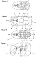
- Figure 5 shows a three seat configuration with a boot space 10A behind the passenger seats 3, 4.
- Figure 6 shows a two seat configuration with one passenger seat folded down with storage space 10A, 10B in the boot and in the cabin.
- Figure 7 shows a driver's seat configuration only, with two passenger seats folded down, with storage spaces 10A, 10B, 10C in the boot and in the cabin. The areas available for storage are shown shaded in Figures 5 - 7 .
- Figures 8-15 illustrate a second embodiment of a seating arrangement according to the invention. This is similar to the arrangement shown in Figures 1-7 but with some small changes in the various dimensions of the layout. Figures 8-15 also show features of the seats and the positions of the occupants therein in a little more detail.
- Figure 8 shows a plan view of a vehicle incorporating this seating arrangement and shows a cabin 11, a driver's seat 12, two rear passenger seats 13, 14, the body 15 of the vehicle, its wheels 16, control pedals 17, a steering wheel 18 and front wheel arches 19.
- the driver's seat comprises a seat base 12A, a seat back 12B and a headrest 12C.
- Rearward portions of the seat base 12A, on each side thereof, are shaped, e.g. by the provision of a cut-out 12D to provide a space to accommodate at least part of a leg of a passenger seated in a rear passenger seat.
- the seat base 12A enables the rear seats 13, 14 (and the inboard leg of a passenger seated therein) to overlap in the lateral direction, e.g. so that the inboard knee of a passenger lies, at least partially, beneath one of the driver's shoulders.
- the inboard shoulder of each passenger thus lies inboard of one of the driver's shoulders, as shown in Figure 9 .
- the spacing D1 between the centre line CL1 of the driver's seat 12 and the centre lines CL2, CL3 of the passenger seats 13, 14 is around 280-380 mm (which is slightly greater than that shown in the first embodiment).
- the overall external width W of the vehicle can, however, still be kept to around 1250mm - 1400mm or less.
- the internal width of the cabin will be less than 1400mm, and preferably less than 1200mm.
- the internal width should, however, preferably be at least 1040mm to accommodate the shoulders of typical adult passengers side by side (in the extreme case that their shoulders are just touching).
- the width S of an adult occupant's shoulders typically lies in the range 450mm to 520mm, this preferably being greater than the lateral spacing D1 of the centre lines of the seats so that the passenger's inboard shoulder lies behind or inboard of one of the driver's shoulders, i.e. so the inboard shoulders of the passengers are spaced from each other by a distance less than S.
- the lateral spacing D1 should also preferably be greater than or equal to the width S so that the inboard shoulders of the passengers are spaced from each other (or at worst, are adjacent each other).
- a preferred relationship between D1 and S can thus be stated as: S / 2 ⁇ D ⁇ 1 ⁇ S .
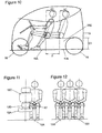
- Figure 10 shows a side view of the vehicle shown in Figure 9 .
- the driver's seat and the passenger seats are arranged so that the occupants are seated in a relatively upright position.
- the seat backs are angled so that they (and the backs of the occupants) are inclined to the vertical at an angle A1, e.g. of around 20 degrees. This angle may be varied to some extend but is preferably less than 30 degrees and most preferably less than 25 degrees.
- the seat base of each of the seats is also spaced from the floor 11A of the cabin so that the occupants are seated in a relatively high position.
- the distance D3 between the upper surface of the seat base 12A which supports the occupant and the floor 11A is preferably in the range 400 - 500mm.
- the occupants' lower legs thus typically make an angle with the vertical of 30 degrees or less, and preferably 25 degrees or less.
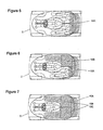
- FIG 11 shows a front view of the driver's seat 12 (with no occupant) and a passenger seated in one of the rear seats.
- the seat back 12B has two main parts: an upper, relatively wide portion 12C for supporting the occupant's upper back and shoulders and a lower relatively narrow portion 12D for supporting the occupant's lower back.
- the passenger's inboard knee K1 overlaps laterally with the driver's seat and is accommodated in a space to the side of the lower seat back portion 12D.
- the driver's seat is shaped to enable the passenger's inboard knee K1 to overlap with the driver's seat in the longitudinal direction (as shown in Figures 8-10 ) and in the lateral direction (as shown in Figure 11 ).
- the wide portion 12C of the seat back typically has a width in the range 400-500mm (which is preferably similar to, or slightly less, than the width of the occupant's shoulders) and the narrow portion 12D typically has a width in the range 150-300mm.
- the space for accommodating the passenger's knee K1 preferably extends laterally into each side of the seat back 12B by at least 50mm and preferably by at least 100mm.
- the seat base 12A (except between the rear cut-outs12D) has a width similar to that of the wide portion 12C of the seat back.
- Figure 12 is a front view of the driver and two passengers sitting in the seating arrangement illustrated in Figures 8-11 . This shows how the passengers' trunks (upper body) overlap in a lateral direction with the driver's trunk.
- Figures 13-15 illustrate three possible configurations of the seating arrangement described above.
- Figure 13 shows a storage space 20A behind the passenger seats.
- the back rests of the passenger seats 13, 14 can be folded down to a substantially horizontal position.
- Figure 14 one is folded down to create further storage space 20B and in figure 15 , both are folded down to create additional storage spaces 20B and 20C.
- the areas available for storage are again shown shaded in Figures 13-15 .
- a child seat may be secured on one or both of the passenger seats.
- the passengers' knees overlap with the driver's body and the driver's seat to some extend as indicated by the distance D2 (see Figure 4 ).
- the size of this distance will depend on the longitudinal position of the driver's seat and the size of the passenger but will typically be in the range of 50mm - 300mm.
- the longitudinal position of the driver's seat 12 is adjustable so the driver can adjust his or her position relative to the control pedals 7 and steering wheel 8 as required.
- the driver's seat 2, 12 is located just forward of the passenger seats 3, 4, 13, 14.
- the rear of the driver's seat base 12A and/or the driver's seat back 12B is located close to the front of the passenger seats 13, 14 (when viewed from above as in Figures 2 and 8 ). If the driver's seat 12 is adjusted forwards, the space between the driver's seat 12 and the passenger seats 13, 14 increases, e.g. by up to 200mm, and if it is adjusted rearwards, it may be moved to a position which overlaps longitudinally with the front of the seat base of the passenger seats 13, 14, e.g. by up to 250mm. This may simply involve overlap between the driver's seat back 12B and the passenger seat base (which is possible as these parts are at different heights). In some cases, it may also involve overlap between the driver's seat base 12A and the passenger seat base (which may be possible if the width of the rear of the driver's seat base 12B is narrower than a gap between the front portions of the two passenger seat bases).
- the occupants sit in relatively upright positions and the passengers' feet are typically on the floor 1A, 11A of the cabin immediately adjacent the position of the driver's seat base 12A.
- the passengers may, however, stretch their legs out further to an extent that their feet rest against the rear side of the wheel arches 9, 19.
- the legs of an adult passenger may be substantially fully extended in this position.
- a further important aspect of the vehicle and seating arrangement described herein is the ease of access to the driver's seat 2, 12 and passenger seats 3, 4, 13, 14.
- One of the reasons why a three seat arrangement, with a centrally positioned driver's seat, has not been widely adopted is the difficulty in getting into and out of this seat as it is spaced some distance from the side of the vehicle.
- One way of alleviating this problem is to extend the entry door into the floor of the cabin so that when the door is opened, at least part of the floor adjacent the driver's seat is also moved. When the door is open, the driver can then position his or her feet on the ground a little closer to the driver's seat. This is the solution used in the McLaren F1 (trade mark) sports car.
- the vehicle cabin is designed so that it can be opened so that at least a portion of the roof and at least one side of the cabin are moved to a position whereby a person may enter through the side of the vehicle by stepping from the ground adjacent the vehicle onto a horizontal floor space 15A or 15B to one the side of the driver's seat 12 (and in front of the passenger seats 13, 14) and is able to stand upright or in a substantially upright position on this floor space.
- At least part of the roof of the cabin is moved to a position so as to provide a clear space extending to a height of at least 1.75m and preferably 1.8m or more, above the floor space 15A and/or 15B.
- a clear space extending to a height of at least 1.75m and preferably 1.8m or more, above the floor space 15A and/or 15B.
- One way is for at least a portion of the cabin roof and at least a portion of one side of the cabin to open upwardly.
- a form of gull-wing door could, for example, be used to achieve this.
- Another option would be to arrange for at least a portion of the cabin roof and at least a portion of one side of the cabin to slide longitudinally.
- the driver can thus stand on this floor space 15A or 15B, then lower themselves to sit on the driver's seat 12 and then swing their body around to face forwards or the driver may stand on this floor space 15A or 15B, then move their feet to the space 15C beneath the steering wheel and behind the control pedals whilst (or at the same time) lowering themselves to a seated position in the driver's seat 12.
- each of the floor spaces 15A, 15B is preferably at least 400mm x 300mm and most preferably at least 500mm x 400mm.
- a further important consideration of the 3-seat arrangement described is the provision of seat belt mountings for each of the seats.
- the seat belt mountings for the passenger seats can be secured to the vehicle body in a conventional manner.
- this is not possible for the driver's seat belt.
- McLaren F1 (trade mark) sports car this problem was overcome by providing a monocoque body structure having structural members at the sides of the driver's seat (as there is no lateral overlap between the driver's seat and the passenger seats).
- the driver's seat is, instead, provided with a frame which is of sufficient strength to transfer loads applied to an upper seat belt mounting secured to the seat back, through the frame, to the seat base and hence to the floor of the vehicle.
- the invention also extends to a seating arrangement for a vehicle, said seating arrangement having at least three seats and comprising two rear passenger seats aligned substantially transversely, and a driver's seat arranged substantially centrally and in front of said two rear passenger seats, wherein said front driver's seat extends rearward beyond the front of each said rear passengers legs.
- the amount of the overlap D2 (see Figure 4 ) will depend upon the relative sizes of the said passengers.
- the vehicle engine is mounted in a space 20D (see Figure 10 ) beneath the floor of the boot space 20A (which is typically at a similar level to the seat bases of the passenger seats 13, 14) and/or beneath the seat bases of the passenger seats 13, 14.
- the fuel tank is preferably mounted beneath the driver's seat and the radiator may be positioned behind the fuel tank.
- the batteries or other energy source may, likewise, be mounted beneath the driver's seat.
- the fuel tank or other energy source is thus located on the midline of the vehicle, substantially midway between the front and rear wheels and in a low position so in a substantially ideal location for the vehicle dynamics.
- the seating arrangement described with its central driving position is advantageous in any type of vehicle, whether or not it is mid-engined.
- rear seats may be provided behind the rear passenger seats shown. Furthermore, it would be possible to provide the two rear seats in a suitably shaped bench seat, for example, connected by upholstery.
- the height of the vehicle is preferably in the range 1.15 - 1.50m and most typically around 1.4 m.
Abstract
Description
- This invention relates to a compact seating arrangement for a vehicle, in particular comprising a central driving seat and two rear passenger seats aligned substantially transversely.
- A variety of seating arrangements comprising a central driver's seat and two rear passenger seats have previously been proposed but these have tended to suffer from various practical limitations or inconveniences so have not been widely adopted. In more recent years, such a seating arrangement for a sports car has been described in
WO9218347 - The present invention seeks to develop this concept further to provide a more compact seating arrangement suitable for use in a compact vehicle.
- Compact vehicles tend to suffer from compromised driver ergonomics because the front wheel arch intrudes into the passenger cabin. This is the case for both left-hand and righthand drive vehicles. The present invention also seeks to provide a compact seating arrangement for a vehicle, which provides better ergonomics for the driver.
- According to a first aspect of the invention there is provided a compact seating arrangement for a vehicle, , wherein the seating arrangement has at least three seats and comprising two rear passenger seats aligned substantially transversely, and a driver's seat arranged substantially centrally and in front of said two rear passenger seats wherein the driver's seat extends transversely so as to be positioned in front of part of each of the passenger seats and extends rearward beyond the front of the legs of the rear passengers when seated in the passenger seats, in which each of the seats has a seat back and a seat base and is arranged to seat a person in a generally upright position, the seat backs being inclined to the vertical at an angle of 30 degrees or less, the or each seat base having an upper surface which supports the occupant of each seat base being spaced 400-500mm above a substantially horizontal floor space provided adjacent the seats, and the passengers' feet being placed on the horizontal floor space on either side of the driver's seat and immediately in front of the passenger seats, whereby the lower legs of the occupants of the seats make an angle with the vertical of 30 degrees or less when their feet are positioned on said floor space adjacent the seats.
- Typically, the driver's seat comprises a seat base on which a driver sits and a seat back for supporting a driver's back; a space or a cut-out being provided on each side of the seat base and/or of the seat back of the driver's seat to allow the innermost leg of each of the passengers to overlap (both transversely and longitudinally) with the position of the driver's seat.
- It would be possible for a common rear bench seat to be provided in which said two rear passenger seats are formed. Alternatively, two separate rear passenger seats may be provided.
- In either case, the arrangements of the seats is such that advantage can be taken of the fact that the human passenger generally has a wider trunk or body than legs, and specifically has shoulders of greater width than the width of the legs. This enables passengers to be comfortably seated on the respective rear seats with the front driver's seat overlapping the legs of the passengers. This overlapping arrangement enables the cabin of a vehicle to be kept relatively narrow and yet provide accommodation for the driver and for at least two passengers sat side by side.
- There is also provided a seating arrangement for a vehicle, said seating arrangement having at least three seats and comprising two rear passenger seats aligned substantially transversely, and a driver's seat arranged substantially centrally and in front of said two rear passenger seats, wherein said front driver's seat extends transversely to overlap part of each said rear passengers legs. The amount of the overlap will depend upon the relative sizes of the said passengers.
- The present invention also extends to a vehicle incorporating a seating arrangement as defined above.
- In a preferred embodiment, the vehicle has an engine which is disposed substantially to the rear of the passenger compartment.
- Other preferred and optional features of the invention will be apparent from the subsidiary claims and from the following description.
- The invention will now be further described, merely by way of example, with reference to the accompanying drawings, in which:
-
Figure 1 shows schematically a plan view of a first embodiment of a compact seating arrangement according to the present invention with the occupants (a driver and two passengers) shown therein; -
Figure 2 shows a schematic plan view from above of a vehicle incorporating the seating arrangement ofFigure 1 (without the occupants); -
Figure 3 is a schematic plan view similar toFigure 1 with various dimensions marked thereon; -
Figure 4 is a schematic side view of a vehicle as shown inFigure 2 with the occupants shown; -
Figures 5, 6 and 7 are schematic plan views illustrating three possible configurations for the seating arrangement shown in the preceding figures; -
Figure 8 is a schematic plan view of a vehicle incorporating a second embodiment of a seating arrangement according to the present invention; -
Figure 9 is a schematic plan view showing occupants in the seating arrangement shown inFigure 8 ; -
Figure 10 is a schematic side view of the vehicle ofFigure 8 with the occupants shown; -
Figure 11 is a schematic front view of the second embodiment illustrating the lateral overlap between the driver's seat and a passenger leg; -
Figure 12 is a schematic front view corresponding toFigure 11 but with all three occupants shown; and -
Figures 13 to 15 are schematic plan views of three possible configurations of the seating arrangement shown inFigure 8 . -
Figures 1 to 3 show schematic plan views of acabin 1 of a vehicle, showing the first embodiment of a compact seating arrangement therein. As will be seen, there is a single, centrally arranged driver'sseat 2 and tworear passenger seats seat 2 is arranged generally in front of the two rear passenger seats, the driver'sseat 2 extends transversely to overlap part of each rear passenger legs L1, L2. The driver's seat is shaped at 2A to provide accommodation for at least a part of the inboard leg of each passenger (as shown inFigures 1 and 3 ). - The three seat arrangement shown in
Figures 1 to 3 is comfortable and provides easy access to theseats seats Figure 3 ). -
Figure 2 shows a plan view of a vehicle incorporating the seating arrangement ofFigure 1 . As described, tworear seats seat 2.Figure 2 also shows thebody 5 of the car, together with itswheels 6. It will be seen that the central position of the driver'sseat 2 enables thisseat 2 to be aligned withcontrol pedals 7 and asteering wheel 8. Thus, as indicated inFigure 2 , even where the car is made to be mid-engined, having its engine (not shown) imemediately to the rear of the passenger compartment, and the driver relatively forwardly, the driver'sseat 2 is aligned with thecontrols - As will be seen from
Figure 2 , the central position for the driver means that there is no need to restrict or otherwise compromise on the positioning and size of the front wheel arches 9. This also means that the wheel lock available, and the consequent turning circle, can be chosen as required. - The central driver's position thus avoids problems normally associated with two-and-four-seater cars, for example, caused by the front wheel arches 9 intruding into the passenger cabin. The central driving position also makes it unnecessary to provide left and right hand drive versions. In addition, the seating arrangement shown in
Figures 1 to 3 enables these advantages of a central driving position to be achieved without having to substantially increase the width of thepassenger cabin 1. - As indicated above, the
passenger cabin 1 preferably has a maximum width W of around 1250mm - 1400mm. This compares favorably with the width of currently available two/four seat compact cars, for example, a Smart fortwo (trade mark) (two seater) is 1559 mm wide, whilst the Citroen C1 (trade mark) (four seater) is 1630mm wide. The central driver'sseat 2 is preferably offset forwardly of the tworear passenger seats Figure 3 ). By this means, the trunk of each passenger is kept to the rear of the driver for comfort and to avoid interference by the passengers with the driver's visibility, whilst the passengers can extend their legs to the sides of the driver. - The centrally positioned, front driver's seat and passenger seat layout described above keeps the overall width of the cabin restricted. The amount of the lateral overlap of the seats will depend upon the relative sizes of the seats, their shapes and the like. The distance D1 between the centre line CL1 of the central driver's
seat 2 and the centre lines CL2, CL3 of eachrear passenger seats Figure 3 ). - It will be appreciated that although the driver's 2 seat is forward of the two
passenger seats passenger cabin 1 so that it is a simple matter to provide sufficient headroom at that position (seeFigure 4 ). - As shown in
Figures 5, 6 and 7 , this seating arrangement also enables easy access to the passenger seats, which in turn provides a flexible load carrying capacity. The passenger seats 3, 4 can be folded down together or individually to provide increased storage capacity.Figure 5 shows a three seat configuration with aboot space 10A behind thepassenger seats Figure 6 shows a two seat configuration with one passenger seat folded down withstorage space Figure 7 shows a driver's seat configuration only, with two passenger seats folded down, withstorage spaces Figures 5 - 7 . -
Figures 8-15 illustrate a second embodiment of a seating arrangement according to the invention. This is similar to the arrangement shown inFigures 1-7 but with some small changes in the various dimensions of the layout.Figures 8-15 also show features of the seats and the positions of the occupants therein in a little more detail. -
Figure 8 shows a plan view of a vehicle incorporating this seating arrangement and shows acabin 11, a driver'sseat 12, two rear passenger seats 13, 14, thebody 15 of the vehicle, itswheels 16,control pedals 17, asteering wheel 18 andfront wheel arches 19. - As shown in
Figure 8 , the driver's seat comprises aseat base 12A, a seat back 12B and aheadrest 12C. Rearward portions of theseat base 12A, on each side thereof, are shaped, e.g. by the provision of a cut-out 12D to provide a space to accommodate at least part of a leg of a passenger seated in a rear passenger seat. By this means, theseat base 12A enables therear seats 13, 14 (and the inboard leg of a passenger seated therein) to overlap in the lateral direction, e.g. so that the inboard knee of a passenger lies, at least partially, beneath one of the driver's shoulders. The inboard shoulder of each passenger thus lies inboard of one of the driver's shoulders, as shown inFigure 9 . - In the arrangement shown in
Figure 9 , the spacing D1 between the centre line CL1 of the driver'sseat 12 and the centre lines CL2, CL3 of the passenger seats 13, 14 is around 280-380 mm (which is slightly greater than that shown in the first embodiment). The overall external width W of the vehicle can, however, still be kept to around 1250mm - 1400mm or less. - The internal width of the cabin will be less than 1400mm, and preferably less than 1200mm. The internal width should, however, preferably be at least 1040mm to accommodate the shoulders of typical adult passengers side by side (in the extreme case that their shoulders are just touching).
- The width S of an adult occupant's shoulders typically lies in the range 450mm to 520mm, this preferably being greater than the lateral spacing D1 of the centre lines of the seats so that the passenger's inboard shoulder lies behind or inboard of one of the driver's shoulders, i.e. so the inboard shoulders of the passengers are spaced from each other by a distance less than S. The lateral spacing D1 should also preferably be greater than or equal to the width S so that the inboard shoulders of the passengers are spaced from each other (or at worst, are adjacent each other). A preferred relationship between D1 and S can thus be stated as:

-
Figure 10 shows a side view of the vehicle shown inFigure 9 . As shown in this Figure (and inFigure 4 described above), the driver's seat and the passenger seats are arranged so that the occupants are seated in a relatively upright position. The seat backs are angled so that they (and the backs of the occupants) are inclined to the vertical at an angle A1, e.g. of around 20 degrees. This angle may be varied to some extend but is preferably less than 30 degrees and most preferably less than 25 degrees. - The seat base of each of the seats is also spaced from the
floor 11A of the cabin so that the occupants are seated in a relatively high position. The distance D3 between the upper surface of theseat base 12A which supports the occupant and thefloor 11A is preferably in the range 400 - 500mm. The occupants' lower legs thus typically make an angle with the vertical of 30 degrees or less, and preferably 25 degrees or less. -
Figure 11 shows a front view of the driver's seat 12 (with no occupant) and a passenger seated in one of the rear seats. As shown, the seat back 12B has two main parts: an upper, relativelywide portion 12C for supporting the occupant's upper back and shoulders and a lower relativelynarrow portion 12D for supporting the occupant's lower back. As illustrated in the Figure, the passenger's inboard knee K1 overlaps laterally with the driver's seat and is accommodated in a space to the side of the lower seat backportion 12D. Thus, the driver's seat is shaped to enable the passenger's inboard knee K1 to overlap with the driver's seat in the longitudinal direction (as shown inFigures 8-10 ) and in the lateral direction (as shown inFigure 11 ). - The
wide portion 12C of the seat back typically has a width in the range 400-500mm (which is preferably similar to, or slightly less, than the width of the occupant's shoulders) and thenarrow portion 12D typically has a width in the range 150-300mm. The space for accommodating the passenger's knee K1 preferably extends laterally into each side of the seat back 12B by at least 50mm and preferably by at least 100mm. As shown, theseat base 12A (except between the rear cut-outs12D) has a width similar to that of thewide portion 12C of the seat back. -
Figure 12 is a front view of the driver and two passengers sitting in the seating arrangement illustrated inFigures 8-11 . This shows how the passengers' trunks (upper body) overlap in a lateral direction with the driver's trunk. -
Figures 13-15 illustrate three possible configurations of the seating arrangement described above.Figure 13 shows astorage space 20A behind the passenger seats. The back rests of the passenger seats 13, 14 can be folded down to a substantially horizontal position. InFigure 14 , one is folded down to createfurther storage space 20B and infigure 15 , both are folded down to createadditional storage spaces Figures 13-15 . In further arrangements (not shown) a child seat may be secured on one or both of the passenger seats. - As shown in
Figures 4 and10 , the passengers' knees overlap with the driver's body and the driver's seat to some extend as indicated by the distance D2 (seeFigure 4 ). The size of this distance will depend on the longitudinal position of the driver's seat and the size of the passenger but will typically be in the range of 50mm - 300mm. The longitudinal position of the driver'sseat 12 is adjustable so the driver can adjust his or her position relative to thecontrol pedals 7 andsteering wheel 8 as required. As shown inFigures 2 and8 , the driver'sseat passenger seats seat base 12A and/or the driver's seat back 12B is located close to the front of the passenger seats 13, 14 (when viewed from above as inFigures 2 and8 ). If the driver'sseat 12 is adjusted forwards, the space between the driver'sseat 12 and the passenger seats 13, 14 increases, e.g. by up to 200mm, and if it is adjusted rearwards, it may be moved to a position which overlaps longitudinally with the front of the seat base of the passenger seats 13, 14, e.g. by up to 250mm. This may simply involve overlap between the driver's seat back 12B and the passenger seat base (which is possible as these parts are at different heights). In some cases, it may also involve overlap between the driver'sseat base 12A and the passenger seat base (which may be possible if the width of the rear of the driver'sseat base 12B is narrower than a gap between the front portions of the two passenger seat bases). - As shown in
Figures 4 and10 , the occupants sit in relatively upright positions and the passengers' feet are typically on thefloor seat base 12A. The passengers may, however, stretch their legs out further to an extent that their feet rest against the rear side of thewheel arches 9, 19. In a preferred arrangement, the legs of an adult passenger may be substantially fully extended in this position. - A further important aspect of the vehicle and seating arrangement described herein is the ease of access to the driver's
seat passenger seats - In the vehicle and seating arrangement described herein, a different solution is used. As the vehicle has particular application as a compact, town car, it is important that access to all of the seats is very easy. To this end, instead of a conventional entry door, the vehicle cabin is designed so that it can be opened so that at least a portion of the roof and at least one side of the cabin are moved to a position whereby a person may enter through the side of the vehicle by stepping from the ground adjacent the vehicle onto a
horizontal floor space floor space 15A and/or 15B. There are a variety of ways for achieving this. One way is for at least a portion of the cabin roof and at least a portion of one side of the cabin to open upwardly. A form of gull-wing door could, for example, be used to achieve this. Another option would be to arrange for at least a portion of the cabin roof and at least a portion of one side of the cabin to slide longitudinally. - The driver can thus stand on this
floor space seat 12 and then swing their body around to face forwards or the driver may stand on thisfloor space space 15C beneath the steering wheel and behind the control pedals whilst (or at the same time) lowering themselves to a seated position in the driver'sseat 12. - Likewise, a passenger may step from the ground adjacent the vehicle onto the
floor space respective passenger seat floor space floor spaces - A further important consideration of the 3-seat arrangement described is the provision of seat belt mountings for each of the seats. The seat belt mountings for the passenger seats can be secured to the vehicle body in a conventional manner. However, as the driver's seat is spaced from the sides of the cabin, this is not possible for the driver's seat belt. In the McLaren F1 (trade mark) sports car, this problem was overcome by providing a monocoque body structure having structural members at the sides of the driver's seat (as there is no lateral overlap between the driver's seat and the passenger seats). In the seating arrangement described herein, the driver's seat is, instead, provided with a frame which is of sufficient strength to transfer loads applied to an upper seat belt mounting secured to the seat back, through the frame, to the seat base and hence to the floor of the vehicle.
- The seating arrangements described above provide several advantages:
- the driver's seat is centrally positioned to give enhanced vision and in line controls for the driver.
- the layout of the driver's seat with the passenger seats enables a compact, but comfortable and accessible, passenger cabin to be provided.
- the seating arrangement is compact so the dimensions of the car, and its weight, can be kept to a minimum.
- The invention also extends to a seating arrangement for a vehicle, said seating arrangement having at least three seats and comprising two rear passenger seats aligned substantially transversely, and a driver's seat arranged substantially centrally and in front of said two rear passenger seats, wherein said front driver's seat extends rearward beyond the front of each said rear passengers legs. As described above, the amount of the overlap D2 (see
Figure 4 ) will depend upon the relative sizes of the said passengers. - The above embodiments have been described with particular reference to a three-seater, mid-engined vehicle. Typically, the vehicle engine is mounted in a
space 20D (seeFigure 10 ) beneath the floor of theboot space 20A (which is typically at a similar level to the seat bases of the passenger seats 13, 14) and/or beneath the seat bases of the passenger seats 13, 14. If the vehicle has an internal combustion engine, the fuel tank is preferably mounted beneath the driver's seat and the radiator may be positioned behind the fuel tank. If the vehicle has an electric motor, the batteries or other energy source may, likewise, be mounted beneath the driver's seat. The fuel tank or other energy source is thus located on the midline of the vehicle, substantially midway between the front and rear wheels and in a low position so in a substantially ideal location for the vehicle dynamics. However, the seating arrangement described with its central driving position is advantageous in any type of vehicle, whether or not it is mid-engined. - If the length of the vehicle is not a problem, additional rear seats may be provided behind the rear passenger seats shown. Furthermore, it would be possible to provide the two rear seats in a suitably shaped bench seat, for example, connected by upholstery.
- As mentioned above, the seating arrangement described is suited to a compact, town vehicle. In particular, it enables a vehicle to be constructed with an overall (external) length of 2.3m or less and an overall (external) width of 1.25m - 4m. This is of significance as a vehicle of these dimensions is able to file sideways into a standard UK parking spaces (which range from 4.5m - 6.6m by 1.8m - 2.7) and it is possible to fit three such vehicles into a 4.5m parking space side by side and four such vehicles into a 6.6m parking space side by side (whilst still allowing sufficient space there between for the occupants to get into and out of the vehicles). It will also be appreciated that this is further enhanced if the entry door is of the type described above which opens upwards or longitudinally and thus does not extend laterally beyond the dimensions of the vehicle when opened (or does so only by a small amount).
- In the closed configuration, the height of the vehicle (from the floor to the top of the roof) is preferably in the range 1.15 - 1.50m and most typically around 1.4 m.
- It will be appreciated that modifications in and variations to the invention as described above may be made within the scope of the present invention.
Claims (8)
- A compact seating arrangement for a vehicle, , wherein the seating arrangement has at least three seats and comprising two rear passenger seats aligned substantially transversely, and a driver's seat arranged substantially centrally and in front of said two rear passenger seats wherein the driver's seat extends transversely so as to be positioned in front of part of each of the passenger seats and extends rearward beyond the front of the legs of the rear passengers when seated in the passenger seats, in which each of the seats has a seat back and a seat base and is arranged to seat a person in a generally upright position, the seat backs being inclined to the vertical at an angle of 30 degrees or less, the or each seat base having an upper surface which supports the occupant of each seat base being spaced 400-500mm above a substantially horizontal floor space provided adjacent the seats, and the passengers' feet being placed on the horizontal floor space on either side of the driver's seat and immediately in front of the passenger seats, whereby the lower legs of the occupants of the seats make an angle with the vertical of 30 degrees or less when their feet are positioned on said floor space adjacent the seats.
- The seating arrangement as claimed in claim 1 in which the lower legs of occupants of the seats make an angle with the vertical of 25 degrees or less.
- The seating arrangement as claimed in claim 1 in which passengers seated on the passenger seats can extend their legs to the sides of the driver's seat.
- The seating arrangement as claimed in claim 3 in which the legs of adult passengers seated on the passenger seats may be substantially fully extended to the sides of the driver's seat.
- The vehicle having a cabin incorporating a compact seating arrangement as claimed in claim 1.
- The vehicle as claimed in claim 5 in which top parts of the three seats, supporting the heads of the occupants, are at a similar height in the cabin.
- The vehicle as claimed in claim 5 having front wheel arches that intrude into the passenger cabin wherein adult occupants of the passenger seats can stretch their legs out to rest their feet against the rear side of said front wheel arches.
- The vehicle as claimed in claim 5 having an overall cabin width in the range 1.25m - 1.4m and an overall length of 2.3m or less.
Applications Claiming Priority (2)
| Application Number | Priority Date | Filing Date | Title |
|---|---|---|---|
| GBGB0704966.1A GB0704966D0 (en) | 2007-03-15 | 2007-03-15 | Compact vehicle seatings arangement |
| EP20080718734 EP2137024B1 (en) | 2007-03-15 | 2008-03-14 | Compact seating arrangement |
Related Parent Applications (1)
| Application Number | Title | Priority Date | Filing Date |
|---|---|---|---|
| EP20080718734 Division EP2137024B1 (en) | 2007-03-15 | 2008-03-14 | Compact seating arrangement |
Publications (1)
| Publication Number | Publication Date |
|---|---|
| EP2939868A1 true EP2939868A1 (en) | 2015-11-04 |
Family
ID=38008460
Family Applications (3)
| Application Number | Title | Priority Date | Filing Date |
|---|---|---|---|
| EP20080718734 Active EP2137024B1 (en) | 2007-03-15 | 2008-03-14 | Compact seating arrangement |
| EP15162080.4A Withdrawn EP2939868A1 (en) | 2007-03-15 | 2008-03-14 | Compact seating arrangement |
| EP15162090.3A Withdrawn EP2939869A1 (en) | 2007-03-15 | 2008-03-14 | Compact seating arrangement |
Family Applications Before (1)
| Application Number | Title | Priority Date | Filing Date |
|---|---|---|---|
| EP20080718734 Active EP2137024B1 (en) | 2007-03-15 | 2008-03-14 | Compact seating arrangement |
Family Applications After (1)
| Application Number | Title | Priority Date | Filing Date |
|---|---|---|---|
| EP15162090.3A Withdrawn EP2939869A1 (en) | 2007-03-15 | 2008-03-14 | Compact seating arrangement |
Country Status (11)
| Country | Link |
|---|---|
| US (3) | US8267456B2 (en) |
| EP (3) | EP2137024B1 (en) |
| JP (4) | JP2010521354A (en) |
| CN (1) | CN101687469B (en) |
| BR (1) | BRPI0808738B1 (en) |
| CA (3) | CA2680427C (en) |
| ES (1) | ES2543165T3 (en) |
| GB (5) | GB0704966D0 (en) |
| MX (1) | MX2009009646A (en) |
| PL (1) | PL2137024T3 (en) |
| WO (1) | WO2008110814A2 (en) |
Families Citing this family (26)
| Publication number | Priority date | Publication date | Assignee | Title |
|---|---|---|---|---|
| GB0704966D0 (en) | 2007-03-15 | 2007-04-25 | Murray Ian G | Compact vehicle seatings arangement |
| GB2471316B (en) | 2009-06-25 | 2014-07-30 | Gordon Murray Design Ltd | Vehicle chassis |
| GB2476279B (en) * | 2009-12-17 | 2016-05-25 | Gordon Murray Design Ltd | Vehicle comprising a rearwardly mounted engine and radiator |
| FR2962105B1 (en) * | 2010-07-01 | 2012-08-10 | Philippe Lamboley | COMPACT MOTOR VEHICLE WITH FOUR WHEELS AND TWO PLACES |
| GB2482172A (en) | 2010-07-22 | 2012-01-25 | Gordon Murray Design Ltd | Chassis element for a vehicle |
| GB201012340D0 (en) | 2010-07-23 | 2010-09-08 | Gordon Murray Design Ltd | A seatt belt arrangement |
| FR2972691A1 (en) * | 2011-03-15 | 2012-09-21 | Peugeot Citroen Automobiles Sa | Device for assisting closing of e.g. front side door of two-door urban electric car, has handle accessible to driver when door is in open position, for exerting tractive effort on traction link to cause swiveling of door to closing position |
| CN103010053A (en) * | 2012-01-13 | 2013-04-03 | 摩尔动力(北京)技术股份有限公司 | Safety seat for vehicle |
| JP5933312B2 (en) * | 2012-03-30 | 2016-06-08 | 本田技研工業株式会社 | vehicle |
| JP5855510B2 (en) * | 2012-03-30 | 2016-02-09 | 本田技研工業株式会社 | vehicle |
| DE102012018500A1 (en) | 2012-09-18 | 2014-03-20 | Innovative Dragon Ltd. | Vehicle in particular taxi |
| GB2508607A (en) | 2012-12-04 | 2014-06-11 | Ford Global Tech Llc | A seating arrangement for a passenger vehicle |
| GB2519309B (en) | 2013-10-16 | 2019-07-10 | Ford Global Tech Llc | A motor vehicle seating arrangement having an armrest |
| DE102015122720B4 (en) * | 2015-12-23 | 2017-07-27 | Grammer Ag | Backrest with integrated upper body support |
| GB2552582B8 (en) * | 2016-07-26 | 2019-11-20 | Ford Global Tech Llc | Vehicle seat forming a shelf in a staggered seating arrangement |
| CN106671749B (en) * | 2017-03-06 | 2024-04-02 | 刘慕华 | Vehicle with a vehicle body having a vehicle body support |
| CN106672077A (en) * | 2017-03-06 | 2017-05-17 | 至玥腾风科技投资集团有限公司 | Vehicle |
| IT201800002912A1 (en) * | 2018-02-21 | 2019-08-21 | Alfazero S P A | INTERNAL LAYOUT |
| EP3914473A4 (en) | 2019-01-23 | 2022-10-19 | Liong, Iwan | Seating arrangement for vehicle |
| US11110821B2 (en) * | 2019-02-11 | 2021-09-07 | Byton North America Corporation | Sliding center module system for vehicle |
| US11772517B2 (en) | 2020-11-09 | 2023-10-03 | Ford Global Technologies, Llc | Vehicular system capable of adjusting a passenger compartment from a child seat arrangement to a second arrangement |
| US11904732B2 (en) | 2020-11-09 | 2024-02-20 | Ford Global Technologies, Llc | Vehicular system capable of adjusting a passenger compartment from a first arrangement to a child care arrangement |
| US11772519B2 (en) | 2020-11-09 | 2023-10-03 | Ford Global Technologies, Llc | Vehicular system capable of adjusting a passenger compartment from a first arrangement to a child seat arrangement |
| US11772520B2 (en) | 2020-11-09 | 2023-10-03 | Ford Global Technologies, Llc | Remote notification and adjustment of a passenger compartment arrangement |
| US11731535B2 (en) | 2020-11-09 | 2023-08-22 | Ford Global Technologies, Llc | Vehicular system capable of adjusting a passenger compartment from a child care arrangement to a second arrangement |
| JP2022108526A (en) * | 2021-01-13 | 2022-07-26 | トヨタ自動車株式会社 | Seat device for vehicle |
Citations (1)
| Publication number | Priority date | Publication date | Assignee | Title |
|---|---|---|---|---|
| WO1992018347A1 (en) | 1991-04-09 | 1992-10-29 | Mclaren Cars N.V. | Vehicle body |
Family Cites Families (45)
| Publication number | Priority date | Publication date | Assignee | Title |
|---|---|---|---|---|
| GB177857A (en) * | 1920-12-31 | 1922-03-31 | John Davenport Siddeley | Improvements in and relating to motor road vehicles |
| GB190040A (en) * | 1922-01-14 | 1922-12-14 | Richard Henry Lea | Improvements in bodies for use on motor vehicles |
| US2190218A (en) * | 1937-02-27 | 1940-02-13 | Packard Motor Car Co | Motor vehicle |
| US2839312A (en) * | 1955-05-18 | 1958-06-17 | Daimler Benz Ag | Combined seating and steering arrangement for vehicles |
| GB979830A (en) * | 1962-06-02 | 1965-01-06 | Soichiro Honda | Motor vehicles |
| DE1430832A1 (en) * | 1963-07-23 | 1969-09-04 | Daimler Benz Ag | Passenger cars, in particular small cars with rear engines |
| GB1126166A (en) * | 1966-07-09 | 1968-09-05 | Pininfarina Spa Carrozzeria | Motor vehicle with a three-seater body |
| FR2040903A5 (en) * | 1969-04-16 | 1971-01-22 | Citroen Sa | |
| JPS5243223A (en) * | 1975-10-01 | 1977-04-05 | Mitsubishi Motors Corp | Four-wheel passenger car |
| US4160534A (en) * | 1977-12-30 | 1979-07-10 | The Boeing Company | Operating station for aircraft refueling boom |
| JPS554257A (en) * | 1978-06-26 | 1980-01-12 | Saburo Imada | Seat for automobile |
| IT1138285B (en) * | 1981-04-30 | 1986-09-17 | Renato Monzini | VEHICLE, FOR THE TRANSPORT OF PEOPLE |
| JPS57205239A (en) * | 1981-06-11 | 1982-12-16 | Mazda Motor Corp | Rear seat of automobile |
| JPS59137832U (en) * | 1983-03-07 | 1984-09-14 | 池田物産株式会社 | car seat |
| JPS59177357U (en) * | 1983-05-12 | 1984-11-27 | 本田技研工業株式会社 | vehicle seat |
| JPS615241U (en) | 1984-06-18 | 1986-01-13 | 富士重工業株式会社 | car seat structure |
| JPS6131237U (en) * | 1984-07-31 | 1986-02-25 | 富士重工業株式会社 | car seat |
| JPS6144329A (en) | 1984-08-07 | 1986-03-04 | Tokyo Electric Co Ltd | Load cell scale |
| JPS6144329U (en) | 1984-08-28 | 1986-03-24 | 富士重工業株式会社 | Lower structure of automobile seat |
| JPH03125676A (en) * | 1989-10-12 | 1991-05-29 | Deele Raumu:Kk | Automobile |
| IT1238121B (en) * | 1989-10-17 | 1993-07-07 | Bulgari Gianni Spa | CAR WITH THREE FRONT SEATS FACED |
| GB2254588B (en) * | 1991-04-09 | 1995-11-08 | Mclaren Cars Nv | Improvements in or relating to vehicles |
| JPH107018A (en) * | 1997-02-25 | 1998-01-13 | Mclaren Cars Nv | Car body |
| US5538309A (en) * | 1991-04-09 | 1996-07-23 | Mclaren Cars N.V. | Vehicle body |
| FR2677601B1 (en) * | 1991-06-12 | 1993-10-08 | Matra Automobile | MOTOR VEHICLE WITH PLATFORM AND FOLDABLE SEATS. |
| FR2684932B1 (en) * | 1991-12-17 | 1996-09-06 | Peugeot | IMPROVED ELECTRIC VEHICLE. |
| DE4323783C2 (en) * | 1993-07-15 | 1997-03-06 | Schmidt Lutz R | Motor vehicle |
| DE29518853U1 (en) * | 1995-10-13 | 1997-02-13 | Mohr Ernst Dipl Ing | Seat arrangement for passenger vehicles or the like. |
| JPH1142140A (en) * | 1997-07-24 | 1999-02-16 | Central Japan Railway Co | Chair |
| JP3649312B2 (en) * | 1997-09-13 | 2005-05-18 | 本田技研工業株式会社 | Driving force transmission device for hybrid vehicle |
| US6056239A (en) * | 1998-08-12 | 2000-05-02 | Carlos Martinez Celis Cantu | Convertible seating and sleeping accommodations for aircraft |
| JP2003182424A (en) * | 2001-12-25 | 2003-07-03 | Fuji Heavy Ind Ltd | Vehicle body structure for pick-up truck |
| US6629721B1 (en) * | 2002-05-02 | 2003-10-07 | Daimlerchrysler Corporation | Multi-positional seating system for a motor vehicle |
| JP2005104262A (en) * | 2003-09-30 | 2005-04-21 | Honda Motor Co Ltd | Seat structure of vehicle |
| JP2005297907A (en) * | 2004-04-15 | 2005-10-27 | Namba Press Works Co Ltd | Vehicle seat |
| CN100519266C (en) * | 2004-05-24 | 2009-07-29 | 本田技研工业株式会社 | Vehicle |
| JP4563840B2 (en) * | 2004-05-24 | 2010-10-13 | 本田技研工業株式会社 | vehicle |
| US20090001764A1 (en) * | 2005-03-16 | 2009-01-01 | Cocky Coach Llc | Vehicle Chassis |
| JP2006327409A (en) * | 2005-05-26 | 2006-12-07 | Mazda Motor Corp | Rear in-cabin structure of vehicle |
| JP4873288B2 (en) * | 2005-10-14 | 2012-02-08 | スズキ株式会社 | Vehicle seat device |
| US7380859B2 (en) * | 2006-06-28 | 2008-06-03 | Ford Global Technologies, Llc | Seating arrangement |
| GB0704966D0 (en) | 2007-03-15 | 2007-04-25 | Murray Ian G | Compact vehicle seatings arangement |
| US7845724B2 (en) * | 2007-09-14 | 2010-12-07 | CCO Holding Corp. | Automotive seating configuration |
| DE102007061208A1 (en) * | 2007-12-19 | 2009-06-25 | Daimler Ag | Roof structure of a body of a motor vehicle |
| DE102011112572A1 (en) * | 2011-09-08 | 2013-03-14 | GM Global Technology Operations LLC (n. d. Gesetzen des Staates Delaware) | Replaceable battery module for an electric vehicle |
-
2007
- 2007-03-15 GB GBGB0704966.1A patent/GB0704966D0/en not_active Ceased
-
2008
- 2008-03-14 CA CA2680427A patent/CA2680427C/en not_active Expired - Fee Related
- 2008-03-14 EP EP20080718734 patent/EP2137024B1/en active Active
- 2008-03-14 CN CN200880008399.0A patent/CN101687469B/en not_active Expired - Fee Related
- 2008-03-14 GB GB1011544A patent/GB2470302B/en not_active Expired - Fee Related
- 2008-03-14 CA CA2886534A patent/CA2886534C/en not_active Expired - Fee Related
- 2008-03-14 CA CA2886536A patent/CA2886536C/en not_active Expired - Fee Related
- 2008-03-14 ES ES08718734.0T patent/ES2543165T3/en active Active
- 2008-03-14 EP EP15162080.4A patent/EP2939868A1/en not_active Withdrawn
- 2008-03-14 WO PCT/GB2008/000892 patent/WO2008110814A2/en active Application Filing
- 2008-03-14 GB GB0917658A patent/GB2462217B/en not_active Expired - Fee Related
- 2008-03-14 JP JP2009553211A patent/JP2010521354A/en active Pending
- 2008-03-14 GB GB1011546A patent/GB2470667B/en not_active Expired - Fee Related
- 2008-03-14 US US12/530,995 patent/US8267456B2/en active Active
- 2008-03-14 PL PL08718734T patent/PL2137024T3/en unknown
- 2008-03-14 MX MX2009009646A patent/MX2009009646A/en active IP Right Grant
- 2008-03-14 BR BRPI0808738-5A patent/BRPI0808738B1/en not_active IP Right Cessation
- 2008-03-14 EP EP15162090.3A patent/EP2939869A1/en not_active Withdrawn
- 2008-03-14 GB GB1011541A patent/GB2471027B/en not_active Expired - Fee Related
-
2012
- 2012-08-08 US US13/569,679 patent/US8851547B2/en not_active Expired - Fee Related
- 2012-08-08 US US13/569,695 patent/US8550530B2/en active Active
-
2014
- 2014-04-23 JP JP2014088967A patent/JP2014133563A/en active Pending
- 2014-04-23 JP JP2014088966A patent/JP2014133562A/en active Pending
-
2015
- 2015-10-28 JP JP2015211751A patent/JP6116643B2/en not_active Expired - Fee Related
Patent Citations (1)
| Publication number | Priority date | Publication date | Assignee | Title |
|---|---|---|---|---|
| WO1992018347A1 (en) | 1991-04-09 | 1992-10-29 | Mclaren Cars N.V. | Vehicle body |
Also Published As
Similar Documents
| Publication | Publication Date | Title |
|---|---|---|
| EP2137024B1 (en) | Compact seating arrangement | |
| US9102243B2 (en) | Seating arrangement for a passenger vehicle | |
| US5538309A (en) | Vehicle body | |
| CN110803072A (en) | Vehicle with a steering wheel | |
| EP0677002B1 (en) | Vehicle body | |
| US9440681B2 (en) | Cabin space structure for all terrain vehicle | |
| GB2254588A (en) | Vehicle seating arrangement. | |
| JP2007153220A (en) | Seat arrangement structure of vehicle | |
| WO2023037377A1 (en) | A vehicle | |
| JP2000351342A (en) | Support structure of vehicular slide seat |
Legal Events
| Date | Code | Title | Description |
|---|---|---|---|
| AC | Divisional application: reference to earlier application |
Ref document number: 2137024 Country of ref document: EP Kind code of ref document: P |
|
| AK | Designated contracting states |
Kind code of ref document: A1 Designated state(s): AT BE BG CH CY CZ DE DK EE ES FI FR GB GR HR HU IE IS IT LI LT LU LV MC MT NL NO PL PT RO SE SI SK TR |
|
| PUAI | Public reference made under article 153(3) epc to a published international application that has entered the european phase |
Free format text: ORIGINAL CODE: 0009012 |
|
| 17P | Request for examination filed |
Effective date: 20160503 |
|
| RBV | Designated contracting states (corrected) |
Designated state(s): AT BE BG CH CY CZ DE DK EE ES FI FR GB GR HR HU IE IS IT LI LT LU LV MC MT NL NO PL PT RO SE SI SK TR |
|
| 17Q | First examination report despatched |
Effective date: 20190425 |
|
| STAA | Information on the status of an ep patent application or granted ep patent |
Free format text: STATUS: THE APPLICATION IS DEEMED TO BE WITHDRAWN |
|
| 18D | Application deemed to be withdrawn |
Effective date: 20200911 |
|
| P01 | Opt-out of the competence of the unified patent court (upc) registered |
Effective date: 20230528 |