EP2939010B1 - Wide dynamic range conductivity measurements in water - Google Patents
Wide dynamic range conductivity measurements in water Download PDFInfo
- Publication number
- EP2939010B1 EP2939010B1 EP13815650.0A EP13815650A EP2939010B1 EP 2939010 B1 EP2939010 B1 EP 2939010B1 EP 13815650 A EP13815650 A EP 13815650A EP 2939010 B1 EP2939010 B1 EP 2939010B1
- Authority
- EP
- European Patent Office
- Prior art keywords
- conductivity
- cell
- value
- fluid
- square wave
- Prior art date
- Legal status (The legal status is an assumption and is not a legal conclusion. Google has not performed a legal analysis and makes no representation as to the accuracy of the status listed.)
- Active
Links
- 238000005259 measurement Methods 0.000 title claims description 68
- XLYOFNOQVPJJNP-UHFFFAOYSA-N water Substances O XLYOFNOQVPJJNP-UHFFFAOYSA-N 0.000 title description 11
- 239000012530 fluid Substances 0.000 claims description 85
- 238000000034 method Methods 0.000 claims description 27
- 238000011084 recovery Methods 0.000 claims description 13
- 230000008569 process Effects 0.000 claims description 10
- 230000000630 rising effect Effects 0.000 claims description 7
- 230000001939 inductive effect Effects 0.000 claims 1
- 239000000919 ceramic Substances 0.000 description 30
- FAPWRFPIFSIZLT-UHFFFAOYSA-M Sodium chloride Chemical compound [Na+].[Cl-] FAPWRFPIFSIZLT-UHFFFAOYSA-M 0.000 description 12
- 150000001875 compounds Chemical class 0.000 description 8
- 230000009021 linear effect Effects 0.000 description 7
- 238000004422 calculation algorithm Methods 0.000 description 6
- 239000011780 sodium chloride Substances 0.000 description 6
- 230000006870 function Effects 0.000 description 5
- 238000005516 engineering process Methods 0.000 description 4
- 150000002500 ions Chemical class 0.000 description 3
- 239000007788 liquid Substances 0.000 description 3
- 101100536354 Drosophila melanogaster tant gene Proteins 0.000 description 2
- 239000003990 capacitor Substances 0.000 description 2
- 238000010586 diagram Methods 0.000 description 2
- 230000004048 modification Effects 0.000 description 2
- 238000012986 modification Methods 0.000 description 2
- 230000009022 nonlinear effect Effects 0.000 description 2
- 230000001960 triggered effect Effects 0.000 description 2
- 102100032620 Cytotoxic granule associated RNA binding protein TIA1 Human genes 0.000 description 1
- 101000654853 Homo sapiens Cytotoxic granule associated RNA binding protein TIA1 Proteins 0.000 description 1
- 238000012897 Levenberg–Marquardt algorithm Methods 0.000 description 1
- 238000004364 calculation method Methods 0.000 description 1
- 230000001419 dependent effect Effects 0.000 description 1
- 230000001627 detrimental effect Effects 0.000 description 1
- 230000003993 interaction Effects 0.000 description 1
- 239000002184 metal Substances 0.000 description 1
- 238000006552 photochemical reaction Methods 0.000 description 1
- 229920006395 saturated elastomer Polymers 0.000 description 1
- 238000000926 separation method Methods 0.000 description 1
- 230000005477 standard model Effects 0.000 description 1
Images


Classifications
-
- G—PHYSICS
- G01—MEASURING; TESTING
- G01N—INVESTIGATING OR ANALYSING MATERIALS BY DETERMINING THEIR CHEMICAL OR PHYSICAL PROPERTIES
- G01N27/00—Investigating or analysing materials by the use of electric, electrochemical, or magnetic means
- G01N27/02—Investigating or analysing materials by the use of electric, electrochemical, or magnetic means by investigating impedance
- G01N27/04—Investigating or analysing materials by the use of electric, electrochemical, or magnetic means by investigating impedance by investigating resistance
- G01N27/06—Investigating or analysing materials by the use of electric, electrochemical, or magnetic means by investigating impedance by investigating resistance of a liquid
- G01N27/08—Investigating or analysing materials by the use of electric, electrochemical, or magnetic means by investigating impedance by investigating resistance of a liquid which is flowing continuously
-
- G—PHYSICS
- G01—MEASURING; TESTING
- G01N—INVESTIGATING OR ANALYSING MATERIALS BY DETERMINING THEIR CHEMICAL OR PHYSICAL PROPERTIES
- G01N27/00—Investigating or analysing materials by the use of electric, electrochemical, or magnetic means
- G01N27/02—Investigating or analysing materials by the use of electric, electrochemical, or magnetic means by investigating impedance
- G01N27/04—Investigating or analysing materials by the use of electric, electrochemical, or magnetic means by investigating impedance by investigating resistance
- G01N27/06—Investigating or analysing materials by the use of electric, electrochemical, or magnetic means by investigating impedance by investigating resistance of a liquid
Definitions
- This present invention is directed to electronic circuits and a method of using said circuits for sensing the conductivity of a fluid.
- Some industrial systems require a liquid having a specific conductivity to be used, such as pure water. Therefore, it is important to monitor the conductivity of the liquid in such systems.
- some conductivity meters measured conductivity over an extended range by dividing up the range into several decades and providing a separate conductivity cell for each decade.
- a conductivity meter that contains multiple conductivity cells is bulky and impractical for industrial applications.
- the separate conductivity cells were only calibrated for one fixed frequency, usually the frequency located in the middle of the decade.
- the measurements associated with values lying at the edges of each decade were not as accurate.
- a conductivity meter for measuring the conductivity of a fluid according to claim 1 is disclosed.
- the square wave pulse train is comprised of a background stage, a measurement pulse, a recovery pulse, and a base stage.
- the square wave pulse train is further comprised of a rest stage.
- the measurement pulse has a duration which is determined by a previous raw conductivity value.
- the measurement pulse has a duration of 1/(2*drive frequency), wherein the drive frequency is determined by a previous raw conductivity value.
- the current flow measurements are values for the net current flowing through the fluid in said cell.
- control unit circuit estimates the raw conductivity value of the fluid in the cell by fitting the current flow measurements to a double exponent decay function.
- the conductivity meter further comprises a thermistor circuit, wherein the thermistor circuit and the control unit circuit are configured to calculate the temperature of the fluid in the cell and apply a temperature correction to the raw conductivity value of the fluid, thereby producing a temperature corrected conductivity value.
- the thermistor circuit is comprised of a thermistor switch, thermistor drive, thermistor, and trans-impedance amplifier.
- the cell circuit trans-impedance amplifier has a feedback resistor value which is determined by a position of a gain control circuit; wherein the position of the gain control circuit is determined by a previous raw conductivity value.
- the cell circuit is further comprised of a polarity switching circuit, wherein the polarity switching circuit is configured to pass voltage to the square wave drive amp and dictate the polarity of the voltage applied to the cell by the square wave drive amp.
- the polarity switching circuit is further comprised of a cell switch and a polarity switch.
- the cell circuit is further comprised of a rectifier configured to rectify the output of the trans-impedance amplifier.
- the current flow measurements are values for the net current flowing through the fluid in the cell.
- the equation is a double exponent decay function.
- the square wave pulse train is comprised of a measurement pulse during which the current flow measurements are taken.
- the square wave pulse train is further comprised of a background stage, recovery pulse, and a base stage.
- the square wave pulse train is further comprised of a rest stage.
- the method further comprises measuring the temperature of the fluid in the cell and applying a temperature correction to the raw conductivity value of the fluid, thereby producing a temperature corrected conductivity value.
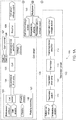
- conductivity meter 100 for measuring conductivity and temperature of a target fluid.
- conductivity meter 100 is comprised of a voltage regulator 105, cell circuit 120, control unit circuit 150, display 160, and thermistor circuit 110.
- Cell circuit 120 is comprised of polarity switching circuit 121, squarewave drive amplifier 124, cell 125, trans-impedance amplifier 126, gain control circuit 127, and rectifier 128.
- Thermistor circuit 110 is comprised of thermistor switch 111, thermistor drive 112, thermistor 113, and trans-impedance amplifier 114.
- Control unit circuit 150 is comprised of multiplexer 153, analog-to-digital converter 152, and control unit 151.
- Control unit 151 has memory 152.
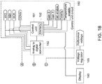
- Voltage regulator 105 provides a reference voltage to analog-to-digital converter 152, cell switch 123, rectifier 128, and thermistor switch 111.
- the rectifier 128 helps to ensure that the voltages arriving at analog-to-digital converter 152 are not negative.
- thermistor switch 111 receives a TEMPERATURE ENABLE signal from control unit 151, which enables control unit 151 to control the output of thermistor drive 112.
- thermistor switch 111 passes the reference voltage from voltage regulator 105 to thermistor drive 112, which applies a precision voltage to thermistor 113 located in cell 125.
- the resistance of the thermistor 113 varies significantly with the temperature of the fluid in cell 125, more so than a standard resistor.
- Trans-impedance amplifier 114 measures the amount of current flowing through thermistor 113 and produces an output voltage that is representative of the amount of current flowing through thermistor 113.
- the output voltage of thermistor trans-impedance amplifier 114, the thermistor circuit voltage output, is directed to multiplexer 153.
- polarity switch 122 receives a POLARITY signal from control unit 151, and cell switch 123 receives a CELL ENABLE signal from control unit 151.
- Polarity switching circuit 121 works in conjunction with control unit 151 to control squarewave drive amplifier 124.
- cell switch 123 When cell switch 123 receives a high CELL ENABLE signal from control unit 151, cell switch 123 passes the reference voltage from voltage regulator 105 to squarewave drive amplifier 124, which causes squarewave drive amplifier 124 to apply a precision voltage to the fluid in cell 125 and results in an electrical current flowing through the fluid in cell 125.
- polarity switch 122 When polarity switch 122 receives a high POLARITY signal from control unit 151, polarity switch 122 grounds the non-inverting input of squarewave drive amplifier 124, which changes the polarity of the precision voltage applied to the fluid in cell 125.
- cell 125 includes two metal electrodes, a first and second electrode, spaced apart from one another and configured to be exposed to the fluid in cell 125, however it is contemplated that in other embodiments, a person having ordinary skill in the art can choose to use a different suitable type of conductivity cell.
- Squarewave drive amplifier 124 applies voltage to the fluid in cell 125 through first electrode of cell 125.
- Cell circuit trans-impedance amplifier 126 measures the amount of current flowing through the fluid in cell 125 and produces an output voltage that is representative of the amount of current flowing through the fluid in cell 125.
- Cell circuit trans-impedance amplifier 126 receives current from cell 125 through the second electrode.
- the gain of trans-impedance amplifier 126 is determined by the setting of gain control circuit switch 130 in gain control circuit 127, which is controlled by the GAIN1 and GAIN0 signals from control unit 151.
- V TIA I CELL R FEEDBACK
- I CELL the amount of current flowing through cell 125
- R FEEDBACK the feedback resistance value that is seen by trans-impedance amplifier 126, which is determined by gain control circuit 127.
- R FEEDBACK of trans-impedance amplifier 126 is a 4.99M resistor in parallel with the resistance value of gain control circuit 127.
- Gain control circuit 127 has four positions, TIA 0-3.
- a 499 ⁇ resistor is placed in parallel with the 4.99M resistor of trans-impedance amplifier 126, which results in a R FEEDBACK value of 499 ⁇ for trans-impedance amplifier 126.
- a 27.4k resistor is placed in parallel with the 4.99M resistor of trans-impedance amplifier 126, which results in a R FEEDBACK value of 27.3k for trans-impedance amplifier 126.
- a 499k resistor is placed in parallel with the 4.99M resistor of trans-impedance amplifier 126, which results in a R FEEDBACK value of 454k for trans-impedance amplifier 126.
- a resistor is not placed in parallel with the 4.99M resistor of trans-impedance amplifier 126, which results in a R FEEDBACK value of 4.99M for trans-impedance amplifier 126.
- Control unit 151 adjusts the gain of trans-impedance amplifier 126 as necessary to prevent the output of trans-impedance amplifier 126 from riding a power rail. This is known as auto-ranging, and allows the conductivity meter to read a wider range of fluid conductivity values than if trans-impedance amplifier 126 had a non-variable feedback resistor value.
- the output voltage from cell trans-impedance amplifier 126 is rectified by rectifier 128.
- the output voltage of rectifier 128, cell circuit voltage output is then directed to multiplexer 153.
- Multiplexer 153 receives a TEMPERATURE ENABLE signal from control unit 151, which allows control unit 151 to control whether multiplexer 153 passes the cell circuit voltage output or the thermistor circuit voltage output to analog-to-digital converter 152. Multiplexer 153 directs the cell circuit voltage output and thermistor circuit voltage output to analog-to-digital converter 152, which passes the digitized values for the cell circuit voltage output and thermistor circuit voltage output to control unit 151. Analog-to-digital converter 152 receives a VIO, SDI, SCK, and CONV signal from control unit 151, which allows control unit 151 to control analog-to-digital converter 152.
- control unit 151 can be a field programmable gate array, microprocessor, microcontroller, programmable logic controller, or another type of controller with similar functionality. Further, it is contemplated that in other embodiments, a person having ordinary skill in the art may choose to use a control unit 151 that also functions as analog-to-digital converter 152, or multiplexer 153 and analog-to-digital converter 152.
- Display 160 makes information contained within control unit 151 available to the user of conductivity meter 100.
- display 160 provides the user with a readout of the conductivity of the fluid in cell 125.
- display 160 provides the user with a readout of the temperature and conductivity of the fluid in cell 125. It is contemplated that in other embodiments, a person having ordinary skill in the art can choose to have display 160 provide the user with any of the information contained within control unit 151.
- display 160 is a touch screen, which allows the user to interact with conductivity meter 100, such as making the selections and entering the information discussed in conjunction with step 410 below. In other embodiments, a keypad is provided, which allows the user to interact with conductivity meter 100, such as making the selections and entering the information discussed in conjunction with step 410 below.
- conductivity meter 100 allows for direct calibration with NIST calibration standard of 1.46mS/cm.
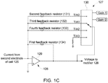
- FIG. 1C shows the interaction between cell trans-impedance amplifier 126 and gain control circuit 127 in greater detail in accordance with an embodiment of the invention.
- cell trans-impedance amplifier 126 is comprised of operational amplifier 129 and first feedback resistor 134 in a trans-impedance amplifier configuration.
- Operational amplifier 129 receives current from second electrode of cell 125 at its inverting input, and outputs voltage to rectifier 128.
- Gain control circuit 127 is comprised of gain control circuit switch 130, second feedback resistor 131, third feedback resistor 132, and fourth feedback resistor 133.
- Gain control circuit switch 130 has a first position (TIA 0), second position (TIA 1), third position (TIA 2), and a fourth position (TIA 3).
- Gain control circuit switch 130 interfaces with and is controlled by control unit 151 through the GAIN1 and GAIN0 control signals from control unit 151.
- the resistance of first feedback resistor 134 is greater than the resistance of fourth feedback resistor 133
- the resistance of fourth feedback resistor 133 is greater than the resistance of third feedback resistor 132
- the resistance of third feedback resistor 132 is greater than the resistance of second feedback resistor 131.
- R FEEDBACK is the feedback resistance value that is seen by operational amplifier 129 of trans-impedance amplifier 126.
- second feedback resistor 131 is placed in parallel with first feedback resistor 134.
- third feedback resistor 132 is placed in parallel with first feedback resistor 134.
- fourth feedback resistor 133 is placed in parallel with first feedback resistor 134.
- another resistor is not placed in parallel with first feedback resistor 134.
- R FEEDBACK seen by operational amplifier 129 in the first through fourth positions of gain control circuit switch 130 is: Position of Gain Control Circuit Switch (130) Value of R FEEDBACK First Position (TIA 0) 1 1 first feedback resistor 134 + 1 second feedback resistor 131 Second Position (TIA 1) 1 1 first feedback resistor 134 + 1 third feedback resistor 132 Third Position (TIA 2) 1 1 first feedback resistor 134 + 1 fourth feedback resistor 133 Fourth Position (TIA 3) first feedback resistor 134
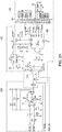
- Polarity switching circuit 121 of conductivity meter 100 is comprised of cell switch 123 and polarity switch 122.
- Cell switch 123 is comprised of: REF DES VALUE Description MANUFACTURER MFG P/N C1 0.1uF CAP.10UF 16V CERAMIC X7R 0603 Kemet C0603C104K4RACTU C53 10uF CAP CERAMIC 10UF 6.3V X5R 0603 Panasonic - ECG ECJ-1VBOJ106M U1 ADG701L IC SWITCH SPST SOT23-6 Analog Devices Inc ADG701 LBRTZ-REEL7 R4 10K RES 10.0K OHM 1/10W 1% 0603 SMD Vishay/Dale CRCW060310KOFKEA
- Polarity switch 122 is comprised of: REF DES VALUE Description MANUFACTURER MFG P/N R36 10K RES 10.0K OHM 1/10W 1% 0603 SMD Vishay/Dale CRCW060310KOFKEA C4 0.1uF CAP .10UF 16V CERAMIC X7R 0603 Kemet C0603C104K4RACTU U3 ADG701L IC SWITCH SPST SOT23-6 Analog Devices Inc ADG701 LBRTZ-REEL7
- Squarewave drive amplifier 124 is comprised of: REF DES VALUE Description MANUFACTURER MFG P/N C59 10pF CAP CERAMIC 10PF 50V NPO 0603 Kemet C0603C100J5GACTU R1 10K/10K RES NET 10K/10K OHM ISO 0805 Susumu RM2012B-103/103-PBVW10 C5 0.1uF CAP .10UF 16V CERAMIC X7R 0603 Kemet C0603C104K4RACTU C8 0.1uF CAP .10UF 16V CERAMIC X7R 0603 Kemet C0603C104K4RACTU U7 LT1722 IC OPAMP PREC 200MHZ TSOT-23-5 Linear Technology LT1722CS5#TRMPBF
- Cell 125 is comprised of a conductivity cell, such as miniature conductivity cell model number ACO 08060, manufactured by GE Analytical Instruments.
- Trans-impedance amplifier 126 is comprised of: REF DES VALUE Description MANUFACTURER MFG P/N C10 2pF CAP CER 2.0PF 50V COG 0603 Murata Electronics GRM1885C1 H2R0CZ01 D R5 4.99M RES 4.99M OHM 1/8W 1% 0805 SMD Vishay/Dale CRCW08054M99FKEA C11 0.1uF CAP .10UF 16V CERAMIC X7R 0603 Kemet C0603C104K4RACTU U4 AD8065 IC OPAMP FET-IN HP HS SOT23-5 Analog Devices Inc AD8065ARTZ-REEL7 C12 0.1uF CAP .10UF 16V CERAMIC X7R 0603 Kemet C0603C104K4RACTU
- Gain control circuit 127 is comprised of: REF DES VALUE Description MANUFACTURER MFG P/N R11 499 RES 1/10W 499 OHM .1% 0805 Stackpole RNCS0805BKE499R R10 27.4K RES 1/10W 27.4K OHM .1% 0805 Stackpole RNCS0805BKE27K4 R3 499K RES 1/10W 499K OHM .1% 0805 Stackpole RNCS0805BKE499K R16 20K RES 20.0K OHM 1/10W 1% 0603 SMD Vishay/Dale CRCW060320K0FKEA C9 0.1uF CAP .10UF 16V CERAMIC X7R 0603 Kemet C0603C104K4RACTU C13 0.1uF CAP .10UF 16V CERAMIC X7R 0603 Kemet C0603C104K4RACTU U5 ADG1404 IC SW MUX ANALOG 4:1 14-TSSOP
- Rectifier 128 is comprised of: REF DES VALUE Description MANUFACTURER MFG P/N C19 10pF CAP CERAMIC 10PF 50V NPO 0603 Kemet C0603C100J5GACTU R12 1K/1K RES NET 1.0K/1.0K OHM ISO 0805 Susumu RM2012B-102/102-PBVW10 C20 0.1uF CAP .10UF 16V CERAMIC X7R 0603 Kemet C0603C104K4RACTU C18 0.1uF CAP .10UF 16V CERAMIC X7R 0603 Kemet C0603C104K4RACTU D1 RB706F-40 DIODE SCHOTTKY 40V 30MA SOT-323 Rohm RB706F-40T106 C31 10uF CAP CERAMIC 10UF 6.3V X5R 0603 Panasonic - ECG ECJ-1VBOJ106M R22 1K/100K RES NET 1.0K/100K OHM ISO 0805
- Multiplexer 153 is comprised of: REF DES VALUE Description MANUFACTURER MFG P/N C28 0.1uF CAP .10UF 16V CERAMIC X7R 0603 Kemet C0603C104K4RACTU R8 10 RES 10.0 OHM 1/10W 1% 0603 SMD Vishay/Dale CRCW060310ROFKEA R9 10 RES 10.0 OHM 1/10W 1% 0603 SMD Vishay/Dale CRCW060310ROFKEA U12 ADG749 IC SWITCH SPDT SC70-6 Analog Devices Inc ADG749BKSZ-REEL7
- Voltage Regulator 105 is comprised of: REF DES VALUE Description MANUFACTURER MFG P/N C32 0.1 uF CAP .10UF 16V CERAMIC X7R 0603 Kemet C0603C104K4RACTU U13 LT1790 IC REF LDO 2.5V MICROPWR SOT23-6 Linear Technology LT1790BCS6-2.5#TRMPBF
- Analog-to-digital converter 152 is comprised of: REF DES VALUE Description MANUFACTURER MFG P/N C25 10uF CAP CERAMIC 10UF 6.3V X5R 0603 Panasonic - ECG ECJ-1VBOJ106M C26 0.1uF CAP .10UF 16V CERAMIC X7R 0603 Kemet C0603C104K4RACTU C30 0.1 uF CAP .10UF 16V CERAMIC X7R 0603 Kemet C0603C104K4RACTU C29 2.7nF CAP CER 2700PF 50V C0G 0603 Murata Electronics GRM1885C1 H272JA01 D C2 0.1uF CAP .10UF 16V CERAMIC X7R 0603 Kemet C0603C104K4RACTU U11 AD7980 ADC 16BIT 1MSPS 2.5LSB 10-MSOP Analog Devices Inc AD7980ARMZRL7
- Thermistor switch 111 is comprised of: REF DES VALUE Description MANUFACTURER MFG P/N C16 0.1uF CAP .10UF 16V CERAMIC X7R 0603 Kemet C0603C104K4RACTU R14 10K RES 10.0K OHM 1/10W 1% 0603 SMD Vishay/Dale CRCW060310KOFKEA C24 10uF CAP CERAMIC 10UF 6.3V X5R 0603 Panasonic - ECG ECJ-1VBOJ106M C35 100pF CAP CERAMIC 100PF 50V NP0 0603 Kemet C0603C101J5GACTU R28 10K RES 10.0K OHM 1/10W 1% 0603 SMD Vishay/Dale CRCW060310KOFKEA U8 ADG701L IC SWITCH SPST SOT23-6 Analog Devices Inc ADG701 LBRTZ-REEL7
- Thermistor drive amplifier 112 is comprised of: REF DES VALUE Description MANUFACTURER MFG P/N R2 10K/10K RES NET 10K/10K OHM ISO 0805 Susumu RM2012B-103/103-PBVW10 C14 0.1uF CAP .10UF 16V CERAMIC X7R 0603 Kemet C0603C104K4RACTU C15 0.1uF CAP .10UF 16V CERAMIC X7R 0603 Kemet C0603C104K4RACTU U9 LT1722 IC OPAMP PREC 200MHZ TSOT-23-5 Linear Technology LT1722CS5#TRMPBF
- Thermistor 113 is comprised of GE Thermometrics part number P60AB104L-COEGK. However, it is contemplated that in other embodiments, a person having ordinary skill in the art can choose to use another suitable thermistor.
- Trans-impedance Amplifier 114 is comprised of: REF DES VALUE Description MANUFACTURER MFG P/N C39 10pF CAP CERAMIC 10PF 50V NP0 0603 Kemet C0603C100J5GACTU R27 20K RES 20.0K OHM 1/10W.1% 0603 SMD Susumu RG1608P-203-B-T5 C33 1uF CAP CERAMIC 1.00UF 16V X5R 0603 Kemet C0603C105K4PACTU C34 1uF CAP CERAMIC 1.00UF 16V X5R 0603 Kemet C0603C105K4PACTU U6 AD8065 IC OPAMP FET-IN HP HS SOT23-5 Analog Devices Inc AD8065ARTZ-REEL7
- Control unit 151 is comprised of: REF DES VALUE Description MANUFACTURER MFG P/N J1 Conn, 20p CONN FPC 20POS .5MM SMD R/A ZIF Molex 52892-2095-C C37 47uF CAP TANT 6.3V 47UF SMD Nichicon F950J476MPAAQ2 C38 47uF CAP TANT 6.3V 47UF SMD Nichicon F950J476MPAAQ2
- Voltage regulator 105 which provides power to analog-to-digital converter 152, is comprised of: REF DES VALUE Description MANUFACTURER MFG P/N U2 TPS71525 IC 2.5V HI-IN LDO V REG SC70-5 Texas Instruments TPS71525DCKR C23 1uF CAP CERAMIC 1.00UF 16V X5R 0603 Kemet C0603C105K4PACTU C6 0.1uF CAP .10UF 16V CERAMIC X7R 0603 Kemet C0603C104K4RACTU
- squarewave drive amplifier 124 applies a square wave pulse train having a known frequency, amplitude, and duration to the fluid in cell 125.
- the square wave pulse train causes a current to flow through the fluid in cell 125.
- Trans-impedance amplifier 126 measures the amount of current flowing through the fluid in cell 125 and produces an output voltage that is representative of the amount of current flowing through the fluid in cell 125.
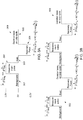
- Fig. 3A shows a representation of one period of the square wave pulse train 300 applied by square wave drive amplifier 124 to the fluid in cell 125 in accordance with an embodiment of conductivity meter 100.
- the square wave pulse train 300 is comprised of a background stage 301, measurement pulse 302, rest stage 303, recovery pulse 304, and base stage 305.
- the background stage 301 of the square wave pulse train 300 has an amplitude of zero volts and a duration of 1/(2*drive frequency).
- the background conductivity of the fluid in cell 125 is measured several times during the background stage 301 by measuring current flowing through the fluid in cell 125 when zero volts is applied to the fluid by square wave drive amplifier 124.
- the measurement pulse 302 of the square wave pulse train 300 has an amplitude of 2.5 volts and a duration ( t M ) of 1/(2*drive frequency).
- the conductivity of the fluid in the cell is measured several times during the measurement pulse 302 by measuring current flowing through the fluid in cell 125 when 2.5 volts is applied to the fluid by square wave drive amplifier 124.
- the rest stage 303 of the square wave pulse train 300 has an amplitude of zero volts and a duration of 50 ⁇ s.
- the rest stage 303 acts to provide separation between the measurement pulse 302 and recovery pulse 304. It is contemplated that in other embodiments, rest stage 303 is not present (has a duration of zero seconds).
- the recovery pulse 304 of the pulse train 300 has an amplitude of negative 2.5 volts and a has a variable duration.
- the recovery pulse 304 discharges any residual charge remaining in cell 125 from measurement pulse 302. For the first iteration of the operations taking place within control unit 151, the duration of the recovery pulse ( t R ) is equal to 1/(2*Drive Frequency).
- the base stage 305 has an amplitude of zero volts and has a duration that extends through the remainder of the duty cycle of square wave pulse train 300. About ten (10) data points are captured during the base stage that are used to calculate the temperature of the fluid in cell 125. The temperature of the fluid in cell 125 is measured when multiplexer 153 receives a TEMPERATURE ENABLE signal from control unit 151. Upon receipt of the TEMPERATURE ENABLE signal, multiplexer 153 directs the thermistor circuit voltage output to analog-to-digital converter 152, which passes the digitized thermistor circuit voltage output to control unit 151.
- FIG. 3B shows two periods of square wave pulse train 300.
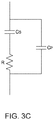
- Figs. 3C-D the equivalent circuit of the conductivity measurement of liquid is shown in Fig. 3C .
- It is a simplified Randles circuit and consists of a resistor (R) in series with a Capacitor (Cs), which represents the double-layer capacity of the electrode/solution interface. That combination has another capacitor (Cp) in parallel.
- the resistor R is the quantity that is to be measured, as conductivity is 1/R.
- the measurement is made by applying square wave pulse train 300 (voltage) to the model (cell 125) and measuring the current flowing through the fluid of cell 125.
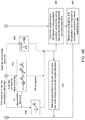
- control unit 151 The operations taking place within control unit 151 are detailed in the flowchart of Figs 4A-B .
- the program for performing the operations detailed in the flowchart of Figs. 4A-B is stored in memory 152 of control unit 151.
- stage 410 thermistor constants, conductivity estimation parameters, and initial square wave pulse train generation parameters for the generation of the first square wave pulse train are entered and loaded into control unit 151.
- the following square wave pulse train generation parameters for the first square wave pulse train are entered and loaded into control unit 151: TIA Gain, Drive Frequency, Measurement Points, and Duty Cycle.
- the duration of the recovery pulse is equal to 1/(2*Drive Frequency).
- the duration of the recovery pulse is variable and its calculation is discussed below in step 460.
- the raw conductivity temperature correction algorithm is selected by user.
- the conductivity estimation parameters: R, A, B, and C are all initialized as having a value of 1.
- control unit 151 In stage 415 control unit 151 is started. In stage 420 the data acquisition process is triggered by control unit 151. In stages 425 and 430, the values for background current travelling through cell 125 during background stage 301, values for raw current travelling through cell 125 during the measurement pulse, and temperature data for the fluid in cell 125 is acquired and indexed by control unit 151.
- the temperature data is comprised of a plurality of values for the amount of current travelling through thermistor 113, which are averaged.
- the values for current travelling through thermistor 113 are ascertained from the corresponding voltage values produced by trans-impedance amplifier 114.
- V is the amplitude in volts of the precision voltage applied to thermistor 113 by thermistor drive amplifier 112.
- I is the average amount of current flowing through thermistor 113.
- Trans-impedance amplifier 114 measures the amount of current flowing through thermistor 113 and outputs a voltage that is representative of the amount of current flowing through thermistor 113.
- Control unit 151 converts the voltage values obtained from trans-impedance amplifier 114 during the base stage of the pulse train into the corresponding values for current flowing through thermistor 113. Control unit 151 then calculates the average resistance of thermistor "R" is obtained by dividing V by I.
- T is the average temperature of thermistor 113 and fluid in cell 125
- R T is the average resistance of thermistor 113.
- a T ", "B T “, and “C T” are thermistor specific constants available on the data sheet for thermistor 113.
- stages 435 and 440 the values for the background current in cell 125 are averaged, and the average background current value is subtracted from each value of raw current travelling through the fluid of cell 125 during the measurement pulse of the square wave pulse train collected in stage 425, thereby creating net values for the current flowing in cell 125 during the square wave pulse train measurement pulse.
- the raw conductivity value for the fluid in cell 125 is calculated using one of the equations in stages 445, 450, or 455.
- Control unit 151 will use the equation of stage 450 if the last raw conductivity value measurement was high (e.g. greater than about 1 mS/cm). However, if the last raw conductivity value measurement was low (e.g. less than about 100 nS/cm), control unit 151 will use the equation of stage 455. Control unit 151 will use equation 445 if the last raw conductivity value measurement was midrange, between the high and low conductivity values. It is contemplated that in other embodiments, a person having ordinary skill in the art can choose to use different suitable high and/or low conductivity values.
- control unit 151 uses the equation of stage 450 during the first iteration of method 400. Additionally, control unit 151 will calculate the raw conductivity (G T ) of the fluid in cell 125 using the equations in stage 450 in the event that the law raw conductivity value measurement was midrange and control unit 151 is unable to fit, within a predetermined length of time, the equation of stage 445 to the net values for the current flowing in cell 125.
- control unit 151 employs a least square method for non-linear equations in order to fit the equation to the net values for the current flowing in cell 125 during the measurement pulse as a function of the elapsed time relative to the rising edge at the beginning of the measurement pulse.
- I V 1 R e ⁇ t RC + 1 ⁇ e ⁇ t RC A e ⁇ t AB
- a least square method minimizes the sum of the squares of the errors made by subsequent iterative equation. It is contemplated that any suitable least square method for non-linear equations can be used, such as, but not limited to, the Levenberg-Marquardt algorithm.
- R", C", “A”, and “B” are conductivity estimation parameters estimated during the equation fitting process
- t is the elapsed time relative to the rising edge at the beginning of the measurement pulse in seconds
- V is the amplitude of the measurement pulse in volts
- I is net value of current flowing through cell 125 in amps at a given time t.
- control unit 151 is able to ascertain the raw conductivity (G T ) of the fluid in cell 125, which is 1/R. However, if, within a predetermined length of time, control unit 151 is unable to fit the equation of stage 445 to the net values for the current flowing in cell 125 during the square wave pulse train measurement pulse, control unit 151 will calculate the raw conductivity (G T ) of the fluid in cell 125 using the equation of stage 450.
- the predetermined length of time for fitting the equation of stage 445 to the net values of current is between about 1ms-100ms.
- a person having ordinary skill in the art can choose a different suitable predetermined length of time depending upon how quickly the user wants a final conductivity result, as well as the computing power of control unit 151.
- control unit 151 When using the single exponent equation of stage 450, control unit 151 employs an ordinary fitting algorithm, which minimizes least squares for linear curves (in log plot), in order to fit the equation to the values for the net current flowing in cell 125 during the square wave pulse train measurement pulse as a function of the elapsed time relative to the rising edge at the beginning of the measurement pulse. Accordingly, a solution to the single exponent equation can be reached using algebra.
- I V R e ⁇ t RC
- control unit 151 calculates an average value for R in order to ascertain the raw conductivity (G T ) of the fluid in cell 125, which is 1/R.
- G T raw conductivity
- R is the resistance of the fluid in cell 125
- N is the data set population
- t is the elapsed time relative to the rising edge at the beginning of the measurement pulse in seconds
- V is the amplitude of the measurement pulse in volts
- i t is value of net current flowing through cell 125 in amps at a given time t.
- stage 480 the raw conductivity temperature correction algorithm, with model chemical compound selected by user in stage 410, is applied to the raw conductivity "G T " to obtain the temperature corrected conductivity value "G T25 ".
- G T is the most recent raw conductivity of the fluid flowing through cell 125 (1/R) calculated in one of stages 445, 450, or 455,
- G T25 is what the conductivity of the fluid flowing through cell 125 would be if the fluid had a temperature of 25°C.
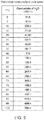
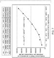
- Gt 25 (H 2 O) and “Gt(H 2 O)” are taken from Table 3, Physical Parameters and Calculated Conductivity and Resistivity, of Light, Truman S., Stuart Licht, Anthony C. Bevilacqua, and Kenneth R. Morashc; The Fundamental Conductivity and Resistivity of Water; Electrochemical and Solid-State Letters. Vol. 8, No. 1 (2005 ): E16-E19, which is herein incorporated by reference and reproduced in relevant part as FIG. 5 .
- the value of " Gt 25 (H 2 O)” is the theoretical conductivity of pure water at 25°C, which is 55.01 nS/cm.
- the value of "Gt(H 2 O)” is determined by the temperature of the fluid flowing through cell 125.
- the "Gt(H 2 O)" value will be 70.97 nS/cm.
- Interpolation is used to ascertain the value of "Gt(H 2 O)" if the temperature of the water flowing through cell 125 is between two temperature values in FIG. 5 . It is contemplated that contents of the table of FIGS. 5 and 6 will be stored in the memory 152 of control unit 151. Control unit 151 will ascertain a value for "Gt(H 2 O)", using interpolation if necessary, based on the temperature of the water flowing through cell 125.
- the polynomial, "P" for NaCl is obtained by adding the conductance values for the Na and Cl ions at each given fluid temperature in FIG. 6 , plotting the summed conductance values for NaCl vs temperature, and fitting a third degree polynomial through the summed conductance values for NaCl.
- a third degree polynomial is used, however, it is contemplated that a person having ordinary skill in the art may choose to fit a higher or lower degree polynomial to the summed conductance values. It is contemplated that in some embodiments, coefficients for polynomial P for one or more commonly used model chemical compounds are programmed in memory 132 at the factory.
- the temperature correction algorithm is based on model chemical compound NaCl.
- a person having ordinary skill in the art can choose to apply a temperature correction algorithm for a different model chemical compound, such as KCl or HCl.
- the values for the coefficients for polynomial P corresponding to one or more model chemical compounds will be stored in memory 152.
- the user will be presented with a listing of the available model chemical compounds and be asked to select a model chemical compound in step 410 for use with the temperature correction algorithm that is applied to the raw conductivity value (G T ) in step 480 to produce a temperature corrected conductivity value (G T25 ).
- a user will be permitted to enter their own coefficient values into control unit 151 and stored in memory 152 for polynomial P in step 410.
- stage 485 the raw conductivity (G T ), temperature, and temperature corrected conductivity (G T25 ) values of the fluid in cell 125 are reported to the user via display 160 and stored in control unit 151.
- stages 460 new square wave pulse train generation parameter values for TIA Gain, Drive Frequency, Measurement Points, and Duty Cycle are selected from the lookup table (Table 1 above) based on the most recent raw conductivity (G T ) value of the fluid flowing through cell 125 calculated in one of stages 445, 450, or 455.
- G T raw conductivity
- the new square wave pulse train parameter values are stored in control unit 151 in stage 490. After stage 490 the next data acquisition process is triggered by control unit 151 in stage 420.
- the new square wave pulse train parameter values stored in control unit 151 determine the properties of the next square wave pulse train in stages 425 and 430.
- the raw conductivity value (G T ) ascertained during the previous iteration of method 400 determines whether the equation of stage 445, 450, or 455 is used by control unit 151 to ascertain the next raw conductivity value using the values for net current flowing in cell 125 acquired during the square wave pulse train measurement pulse in stage 425.
- the raw conductivity value ascertained during the previous iteration of method 400 is used to determine the position of gain control circuit switch 130, which determines the cell circuit trans-impedance amplifier feedback resistor value. Further, the raw conductivity value ascertained during the previous iteration of method 400 is also used to determine the new square wave pulse train generation parameter values, and properties of the next square wave pulse train in stages 425 and 430.
Landscapes
- Chemical & Material Sciences (AREA)
- Chemical Kinetics & Catalysis (AREA)
- Electrochemistry (AREA)
- Physics & Mathematics (AREA)
- Health & Medical Sciences (AREA)
- Life Sciences & Earth Sciences (AREA)
- Analytical Chemistry (AREA)
- Biochemistry (AREA)
- General Health & Medical Sciences (AREA)
- General Physics & Mathematics (AREA)
- Immunology (AREA)
- Pathology (AREA)
- Investigating Or Analyzing Materials By The Use Of Electric Means (AREA)
- Measurement Of Resistance Or Impedance (AREA)
Applications Claiming Priority (2)
| Application Number | Priority Date | Filing Date | Title |
|---|---|---|---|
| US13/728,497 US9116099B2 (en) | 2012-12-27 | 2012-12-27 | Wide dynamic range conductivity measurements in water |
| PCT/US2013/075542 WO2014105501A1 (en) | 2012-12-27 | 2013-12-17 | Wide dynamic range conductivity measurements in water |
Publications (2)
| Publication Number | Publication Date |
|---|---|
| EP2939010A1 EP2939010A1 (en) | 2015-11-04 |
| EP2939010B1 true EP2939010B1 (en) | 2021-03-24 |
Family
ID=49911826
Family Applications (1)
| Application Number | Title | Priority Date | Filing Date |
|---|---|---|---|
| EP13815650.0A Active EP2939010B1 (en) | 2012-12-27 | 2013-12-17 | Wide dynamic range conductivity measurements in water |
Country Status (6)
| Country | Link |
|---|---|
| US (1) | US9116099B2 (enExample) |
| EP (1) | EP2939010B1 (enExample) |
| JP (1) | JP6396321B2 (enExample) |
| CN (1) | CN105074443B (enExample) |
| CA (1) | CA2896325C (enExample) |
| WO (1) | WO2014105501A1 (enExample) |
Families Citing this family (2)
| Publication number | Priority date | Publication date | Assignee | Title |
|---|---|---|---|---|
| JP2019192663A (ja) * | 2018-04-18 | 2019-10-31 | 東芝メモリ株式会社 | 半導体メモリ |
| CN115372701A (zh) * | 2021-05-20 | 2022-11-22 | 梅特勒-托利多仪器(上海)有限公司 | 一种电导率测量装置 |
Citations (1)
| Publication number | Priority date | Publication date | Assignee | Title |
|---|---|---|---|---|
| US5260663A (en) * | 1992-07-14 | 1993-11-09 | Anatel Corporation | Methods and circuits for measuring the conductivity of solutions |
Family Cites Families (42)
| Publication number | Priority date | Publication date | Assignee | Title |
|---|---|---|---|---|
| US3604016A (en) | 1969-02-06 | 1971-09-14 | Thermo Electron Corp | Multiple function blood coupler |
| US3661748A (en) | 1970-04-07 | 1972-05-09 | Instrumentation Labor Inc | Fault sensing instrumentation |
| US3816671A (en) | 1972-04-06 | 1974-06-11 | Thermo Electron Corp | Electret transducer cartridge and case |
| US3772591A (en) | 1972-04-12 | 1973-11-13 | Fisher Scientific Co | Method and apparatus for analyzing blood properties |
| US4190827A (en) | 1976-05-18 | 1980-02-26 | Mcnab, Incorporated | Multichannel salinity meter |
| US4132944A (en) | 1976-10-07 | 1979-01-02 | Simmonds Precision Products, Inc. | Apparatus for monitoring electrical properties of a liquid |
| US4469760A (en) | 1981-09-08 | 1984-09-04 | Electric Power Research, Institute | Redox battery including a bromine positive electrode and a chromium ion negative electrode, and method |
| US4482967A (en) | 1981-09-18 | 1984-11-13 | Dionex Corporation | Conductivity detector and method |
| CA1227247A (en) | 1985-02-05 | 1987-09-22 | Thomas M. Dauphinee | Liquid conductivity measuring circuit |
| US4751189A (en) | 1986-03-11 | 1988-06-14 | Dionex Corporation | Method for balancing background conductivity for ion chromatography |
| US4786875A (en) | 1986-07-22 | 1988-11-22 | General Signal Corporation | Conductivity measuring circuit |
| NL8700744A (nl) * | 1987-03-30 | 1988-10-17 | Yokogawa Electrofact Bv | Werkwijze en inrichting voor het meten van het geleidingsvermogen van een vloeistof, waarmede de invloed van polarisatie wordt tegengegaan. |
| US4806912A (en) | 1987-06-19 | 1989-02-21 | Clack Robert A | Monitoring system for a liquid purification system |
| US4851818A (en) | 1988-04-01 | 1989-07-25 | Eastman Kodak Company | Electronic controller for a water purifying unit |
| US5221448A (en) | 1990-01-25 | 1993-06-22 | Spectra-Physics Analytical, Inc. | Buffer gradient and temperature gradient capillary electrophoresis |
| GB9110207D0 (en) | 1991-05-10 | 1991-07-03 | Fisons Plc | Process for the manufacture of a multipolar elongate-electrode lens or mass filter |
| US5317275A (en) | 1992-01-13 | 1994-05-31 | Orbital Sciences Corporation | Conductance measurement circuit with wide dynamic range |
| US5677190A (en) | 1994-12-14 | 1997-10-14 | Anatel Corporation | Cell and circuit for monitoring photochemical reactions |
| US5612622A (en) * | 1994-12-28 | 1997-03-18 | Optical Solutions, Inc. | Apparatus for identifying particular entities in a liquid using electrical conductivity characteristics |
| US5708363A (en) | 1995-10-16 | 1998-01-13 | Signet Scientific Company | Liquid conductivity measurement system using a variable-frequency AC voltage |
| US6529841B2 (en) * | 1998-05-13 | 2003-03-04 | Johnson Diversey, Inc. | Apparatus and method for conductivity measurement including probe contamination compensation |
| JP3628234B2 (ja) * | 2000-04-26 | 2005-03-09 | 三菱電機株式会社 | ガス同定方法、ガス定量方法およびガス同定または定量装置 |
| WO2001099121A1 (en) | 2000-06-21 | 2001-12-27 | Honeywell International, Inc. | Ethylene-vinyl acetate copolymer waxes |
| US6451613B1 (en) | 2000-09-06 | 2002-09-17 | Anatel Corporation | Instruments for measuring the total organic carbon content of water |
| JP2002330752A (ja) * | 2001-05-08 | 2002-11-19 | Sanden Corp | 微生物数測定装置 |
| US6842017B2 (en) * | 2001-05-17 | 2005-01-11 | Siemens Vdo Automotive Corporation | Fuel cell mixture sensor |
| GB0316742D0 (en) | 2003-07-17 | 2003-08-20 | Fermentas Uab | Electrophoretic gels and their manufacture |
| US7442297B2 (en) | 2005-02-28 | 2008-10-28 | Barnstead/Thermolyne Corp. | Remote water dispensing device and methods for operating such remote water dispensing devices |
| CA2613332A1 (en) * | 2005-05-10 | 2007-07-12 | Michigan State University | Customizable and renewable nanostructured interface for bioelectronic applications |
| CN1821763A (zh) * | 2006-03-22 | 2006-08-23 | 黄伟忠 | 一种溶液电导率的测量方法 |
| CN100541208C (zh) * | 2006-08-30 | 2009-09-16 | 梅特勒-托利多仪器(上海)有限公司 | 溶液电导率的测量方法 |
| CN100485375C (zh) * | 2006-09-27 | 2009-05-06 | 浙江大学 | 一种便携式智能水质电导检测装置 |
| US8038868B2 (en) | 2006-10-04 | 2011-10-18 | Thermo Orion, Inc. | Micro PH electrode (reference electrode) |
| US9395352B2 (en) * | 2007-04-06 | 2016-07-19 | Arizona Board Of Regents On Behalf Of Arizona State University | Devices and methods for target molecule characterization |
| US7550979B2 (en) * | 2007-05-29 | 2009-06-23 | Georg Fischer Signet Llc | System and method for measuring conductivity of fluid |
| FR2932270B1 (fr) * | 2008-06-06 | 2010-07-30 | Millipore Corp | Methode et dispositif de mesure de la purete d'une eau ultrapure |
| US8172999B2 (en) | 2008-08-14 | 2012-05-08 | Thermo Orion, Inc. | Low maintenance reference electrode for electrochemical measurements |
| US8552750B2 (en) | 2009-01-29 | 2013-10-08 | D-2, Inc. | Apparatus and method for the measurement of electrical conductivity and dielectric constant of high impedance fluids |
| DE202009002192U1 (de) | 2009-02-16 | 2009-04-23 | Thermo Fisher Scientific (Bremen) Gmbh | Elektrode zur Beeinflussung der Ionenbewegung in Massenspektrometern |
| US8022355B2 (en) | 2009-08-04 | 2011-09-20 | Thermo Fisher Scientific Inc. | Scintillation detector gain control system using reference radiation |
| WO2011106272A1 (en) * | 2010-02-23 | 2011-09-01 | Merck Sharp & Dohme Corp. | Novel binding assays useful in identifying antibodies with altered half-lives |
| DE102012104708B3 (de) | 2012-05-31 | 2013-07-18 | Dionex Softron Gmbh | Verfahren zur Probenaufnahme |
-
2012
- 2012-12-27 US US13/728,497 patent/US9116099B2/en active Active
-
2013
- 2013-12-17 WO PCT/US2013/075542 patent/WO2014105501A1/en not_active Ceased
- 2013-12-17 JP JP2015550466A patent/JP6396321B2/ja active Active
- 2013-12-17 CA CA2896325A patent/CA2896325C/en active Active
- 2013-12-17 CN CN201380073973.1A patent/CN105074443B/zh active Active
- 2013-12-17 EP EP13815650.0A patent/EP2939010B1/en active Active
Patent Citations (1)
| Publication number | Priority date | Publication date | Assignee | Title |
|---|---|---|---|---|
| US5260663A (en) * | 1992-07-14 | 1993-11-09 | Anatel Corporation | Methods and circuits for measuring the conductivity of solutions |
Also Published As
| Publication number | Publication date |
|---|---|
| JP6396321B2 (ja) | 2018-09-26 |
| CN105074443A (zh) | 2015-11-18 |
| EP2939010A1 (en) | 2015-11-04 |
| JP2016508223A (ja) | 2016-03-17 |
| WO2014105501A1 (en) | 2014-07-03 |
| US20140184251A1 (en) | 2014-07-03 |
| CA2896325C (en) | 2017-06-13 |
| US9116099B2 (en) | 2015-08-25 |
| CA2896325A1 (en) | 2014-07-03 |
| CN105074443B (zh) | 2017-03-22 |
Similar Documents
| Publication | Publication Date | Title |
|---|---|---|
| CN1950695B (zh) | 用于测试气体传感器与校正气体传感器输出的方法和设备 | |
| ES2390401T3 (es) | Método y dispositivo para medir la conductividad de un líquido puro o ultrapuro | |
| Gunning et al. | The conductance and ionic mobilities for aqueous solutions of potassium and sodium chloride at temperatures from 15° to 45° C | |
| US9851337B2 (en) | Universal water condition monitoring device | |
| JP5910683B2 (ja) | ガス濃度検出装置 | |
| CA3005273C (en) | Sensor interrogation with fast recovery | |
| US20200292480A1 (en) | Multi-gas sensing system | |
| US20160097761A1 (en) | Gas measurement apparatus, gas measurement system, gas measurement method, and gas measurement program | |
| EP2939010B1 (en) | Wide dynamic range conductivity measurements in water | |
| CN108618206B (zh) | 烟具设备及用于该烟具设备的测温控温方法 | |
| Morrow et al. | The time-dependent development of electric double-layers in pure water at metal electrodes: the effect of an applied voltage on the local pH | |
| Arévalo-Ramírez et al. | Low cost potentiostat: Criteria and considerations for its design and construction | |
| Yun et al. | A novel approach for extracting contact impedance of electrode/electrolyte interface by minimizing error between impulse response and system function | |
| Lien et al. | Optimizing bismuth-modified graphene-carbon nanotube composite-coated screen printed electrode for lead-ion sensing through the experimental design strategy | |
| JP4575861B2 (ja) | 温度補償機能付検出装置 | |
| Knyziak et al. | Measurement methods of ionization current and electric charges in radiation dosimetry | |
| Bauer et al. | Second-harmonic alternating current polarography | |
| IL320009A (en) | Sensor including measurement circuits for determining resistance and capacitance of an environmental condition and a method of operating such a sensor | |
| JP6833365B2 (ja) | 水位測定装置および水位測定装置の製造方法 | |
| Roubal et al. | Design of electrometric amplifier for aspiration condenser measurement | |
| RU2603338C1 (ru) | Способ калибровки датчика, содержащего термочувствительный элемент | |
| CN109752134A (zh) | 一种气体压力的检测方法及装置 | |
| CN118938116A (zh) | 电能补偿方法、装置、电能表和计算机可读存储介质 | |
| Neagu et al. | Analysis of relaxation parameters and their distributions using fractional polarization thermally stimulated discharge currents | |
| JPH07209247A (ja) | 電気化学式ガスセンサの温度補償機能付きガス感知装置 |
Legal Events
| Date | Code | Title | Description |
|---|---|---|---|
| PUAI | Public reference made under article 153(3) epc to a published international application that has entered the european phase |
Free format text: ORIGINAL CODE: 0009012 |
|
| 17P | Request for examination filed |
Effective date: 20150727 |
|
| AK | Designated contracting states |
Kind code of ref document: A1 Designated state(s): AL AT BE BG CH CY CZ DE DK EE ES FI FR GB GR HR HU IE IS IT LI LT LU LV MC MK MT NL NO PL PT RO RS SE SI SK SM TR |
|
| AX | Request for extension of the european patent |
Extension state: BA ME |
|
| DAX | Request for extension of the european patent (deleted) | ||
| STAA | Information on the status of an ep patent application or granted ep patent |
Free format text: STATUS: EXAMINATION IS IN PROGRESS |
|
| 17Q | First examination report despatched |
Effective date: 20171205 |
|
| RAP1 | Party data changed (applicant data changed or rights of an application transferred) |
Owner name: BL TECHNOLOGIES, INC. |
|
| GRAP | Despatch of communication of intention to grant a patent |
Free format text: ORIGINAL CODE: EPIDOSNIGR1 |
|
| STAA | Information on the status of an ep patent application or granted ep patent |
Free format text: STATUS: GRANT OF PATENT IS INTENDED |
|
| GRAS | Grant fee paid |
Free format text: ORIGINAL CODE: EPIDOSNIGR3 |
|
| INTG | Intention to grant announced |
Effective date: 20210122 |
|
| GRAA | (expected) grant |
Free format text: ORIGINAL CODE: 0009210 |
|
| STAA | Information on the status of an ep patent application or granted ep patent |
Free format text: STATUS: THE PATENT HAS BEEN GRANTED |
|
| AK | Designated contracting states |
Kind code of ref document: B1 Designated state(s): AL AT BE BG CH CY CZ DE DK EE ES FI FR GB GR HR HU IE IS IT LI LT LU LV MC MK MT NL NO PL PT RO RS SE SI SK SM TR |
|
| REG | Reference to a national code |
Ref country code: GB Ref legal event code: FG4D |
|
| REG | Reference to a national code |
Ref country code: CH Ref legal event code: EP |
|
| REG | Reference to a national code |
Ref country code: DE Ref legal event code: R096 Ref document number: 602013076468 Country of ref document: DE |
|
| REG | Reference to a national code |
Ref country code: IE Ref legal event code: FG4D |
|
| REG | Reference to a national code |
Ref country code: AT Ref legal event code: REF Ref document number: 1375011 Country of ref document: AT Kind code of ref document: T Effective date: 20210415 |
|
| REG | Reference to a national code |
Ref country code: LT Ref legal event code: MG9D |
|
| PG25 | Lapsed in a contracting state [announced via postgrant information from national office to epo] |
Ref country code: HR Free format text: LAPSE BECAUSE OF FAILURE TO SUBMIT A TRANSLATION OF THE DESCRIPTION OR TO PAY THE FEE WITHIN THE PRESCRIBED TIME-LIMIT Effective date: 20210324 Ref country code: FI Free format text: LAPSE BECAUSE OF FAILURE TO SUBMIT A TRANSLATION OF THE DESCRIPTION OR TO PAY THE FEE WITHIN THE PRESCRIBED TIME-LIMIT Effective date: 20210324 Ref country code: GR Free format text: LAPSE BECAUSE OF FAILURE TO SUBMIT A TRANSLATION OF THE DESCRIPTION OR TO PAY THE FEE WITHIN THE PRESCRIBED TIME-LIMIT Effective date: 20210625 Ref country code: BG Free format text: LAPSE BECAUSE OF FAILURE TO SUBMIT A TRANSLATION OF THE DESCRIPTION OR TO PAY THE FEE WITHIN THE PRESCRIBED TIME-LIMIT Effective date: 20210624 Ref country code: NO Free format text: LAPSE BECAUSE OF FAILURE TO SUBMIT A TRANSLATION OF THE DESCRIPTION OR TO PAY THE FEE WITHIN THE PRESCRIBED TIME-LIMIT Effective date: 20210624 |
|
| PG25 | Lapsed in a contracting state [announced via postgrant information from national office to epo] |
Ref country code: RS Free format text: LAPSE BECAUSE OF FAILURE TO SUBMIT A TRANSLATION OF THE DESCRIPTION OR TO PAY THE FEE WITHIN THE PRESCRIBED TIME-LIMIT Effective date: 20210324 Ref country code: LV Free format text: LAPSE BECAUSE OF FAILURE TO SUBMIT A TRANSLATION OF THE DESCRIPTION OR TO PAY THE FEE WITHIN THE PRESCRIBED TIME-LIMIT Effective date: 20210324 Ref country code: SE Free format text: LAPSE BECAUSE OF FAILURE TO SUBMIT A TRANSLATION OF THE DESCRIPTION OR TO PAY THE FEE WITHIN THE PRESCRIBED TIME-LIMIT Effective date: 20210324 |
|
| REG | Reference to a national code |
Ref country code: NL Ref legal event code: MP Effective date: 20210324 |
|
| REG | Reference to a national code |
Ref country code: AT Ref legal event code: MK05 Ref document number: 1375011 Country of ref document: AT Kind code of ref document: T Effective date: 20210324 |
|
| PG25 | Lapsed in a contracting state [announced via postgrant information from national office to epo] |
Ref country code: NL Free format text: LAPSE BECAUSE OF FAILURE TO SUBMIT A TRANSLATION OF THE DESCRIPTION OR TO PAY THE FEE WITHIN THE PRESCRIBED TIME-LIMIT Effective date: 20210324 |
|
| PG25 | Lapsed in a contracting state [announced via postgrant information from national office to epo] |
Ref country code: SM Free format text: LAPSE BECAUSE OF FAILURE TO SUBMIT A TRANSLATION OF THE DESCRIPTION OR TO PAY THE FEE WITHIN THE PRESCRIBED TIME-LIMIT Effective date: 20210324 Ref country code: AT Free format text: LAPSE BECAUSE OF FAILURE TO SUBMIT A TRANSLATION OF THE DESCRIPTION OR TO PAY THE FEE WITHIN THE PRESCRIBED TIME-LIMIT Effective date: 20210324 Ref country code: LT Free format text: LAPSE BECAUSE OF FAILURE TO SUBMIT A TRANSLATION OF THE DESCRIPTION OR TO PAY THE FEE WITHIN THE PRESCRIBED TIME-LIMIT Effective date: 20210324 Ref country code: CZ Free format text: LAPSE BECAUSE OF FAILURE TO SUBMIT A TRANSLATION OF THE DESCRIPTION OR TO PAY THE FEE WITHIN THE PRESCRIBED TIME-LIMIT Effective date: 20210324 Ref country code: EE Free format text: LAPSE BECAUSE OF FAILURE TO SUBMIT A TRANSLATION OF THE DESCRIPTION OR TO PAY THE FEE WITHIN THE PRESCRIBED TIME-LIMIT Effective date: 20210324 |
|
| PG25 | Lapsed in a contracting state [announced via postgrant information from national office to epo] |
Ref country code: IS Free format text: LAPSE BECAUSE OF FAILURE TO SUBMIT A TRANSLATION OF THE DESCRIPTION OR TO PAY THE FEE WITHIN THE PRESCRIBED TIME-LIMIT Effective date: 20210724 Ref country code: SK Free format text: LAPSE BECAUSE OF FAILURE TO SUBMIT A TRANSLATION OF THE DESCRIPTION OR TO PAY THE FEE WITHIN THE PRESCRIBED TIME-LIMIT Effective date: 20210324 Ref country code: RO Free format text: LAPSE BECAUSE OF FAILURE TO SUBMIT A TRANSLATION OF THE DESCRIPTION OR TO PAY THE FEE WITHIN THE PRESCRIBED TIME-LIMIT Effective date: 20210324 Ref country code: PL Free format text: LAPSE BECAUSE OF FAILURE TO SUBMIT A TRANSLATION OF THE DESCRIPTION OR TO PAY THE FEE WITHIN THE PRESCRIBED TIME-LIMIT Effective date: 20210324 Ref country code: PT Free format text: LAPSE BECAUSE OF FAILURE TO SUBMIT A TRANSLATION OF THE DESCRIPTION OR TO PAY THE FEE WITHIN THE PRESCRIBED TIME-LIMIT Effective date: 20210726 Ref country code: ES Free format text: LAPSE BECAUSE OF FAILURE TO SUBMIT A TRANSLATION OF THE DESCRIPTION OR TO PAY THE FEE WITHIN THE PRESCRIBED TIME-LIMIT Effective date: 20210324 |
|
| REG | Reference to a national code |
Ref country code: DE Ref legal event code: R097 Ref document number: 602013076468 Country of ref document: DE |
|
| PG25 | Lapsed in a contracting state [announced via postgrant information from national office to epo] |
Ref country code: DK Free format text: LAPSE BECAUSE OF FAILURE TO SUBMIT A TRANSLATION OF THE DESCRIPTION OR TO PAY THE FEE WITHIN THE PRESCRIBED TIME-LIMIT Effective date: 20210324 Ref country code: AL Free format text: LAPSE BECAUSE OF FAILURE TO SUBMIT A TRANSLATION OF THE DESCRIPTION OR TO PAY THE FEE WITHIN THE PRESCRIBED TIME-LIMIT Effective date: 20210324 |
|
| PLBE | No opposition filed within time limit |
Free format text: ORIGINAL CODE: 0009261 |
|
| STAA | Information on the status of an ep patent application or granted ep patent |
Free format text: STATUS: NO OPPOSITION FILED WITHIN TIME LIMIT |
|
| PG25 | Lapsed in a contracting state [announced via postgrant information from national office to epo] |
Ref country code: SI Free format text: LAPSE BECAUSE OF FAILURE TO SUBMIT A TRANSLATION OF THE DESCRIPTION OR TO PAY THE FEE WITHIN THE PRESCRIBED TIME-LIMIT Effective date: 20210324 |
|
| 26N | No opposition filed |
Effective date: 20220104 |
|
| PG25 | Lapsed in a contracting state [announced via postgrant information from national office to epo] |
Ref country code: IS Free format text: LAPSE BECAUSE OF FAILURE TO SUBMIT A TRANSLATION OF THE DESCRIPTION OR TO PAY THE FEE WITHIN THE PRESCRIBED TIME-LIMIT Effective date: 20210724 |
|
| PG25 | Lapsed in a contracting state [announced via postgrant information from national office to epo] |
Ref country code: MC Free format text: LAPSE BECAUSE OF FAILURE TO SUBMIT A TRANSLATION OF THE DESCRIPTION OR TO PAY THE FEE WITHIN THE PRESCRIBED TIME-LIMIT Effective date: 20210324 |
|
| REG | Reference to a national code |
Ref country code: CH Ref legal event code: PL |
|
| REG | Reference to a national code |
Ref country code: BE Ref legal event code: MM Effective date: 20211231 |
|
| PG25 | Lapsed in a contracting state [announced via postgrant information from national office to epo] |
Ref country code: LU Free format text: LAPSE BECAUSE OF NON-PAYMENT OF DUE FEES Effective date: 20211217 Ref country code: IE Free format text: LAPSE BECAUSE OF NON-PAYMENT OF DUE FEES Effective date: 20211217 |
|
| PG25 | Lapsed in a contracting state [announced via postgrant information from national office to epo] |
Ref country code: BE Free format text: LAPSE BECAUSE OF NON-PAYMENT OF DUE FEES Effective date: 20211231 |
|
| PG25 | Lapsed in a contracting state [announced via postgrant information from national office to epo] |
Ref country code: LI Free format text: LAPSE BECAUSE OF NON-PAYMENT OF DUE FEES Effective date: 20211231 Ref country code: CH Free format text: LAPSE BECAUSE OF NON-PAYMENT OF DUE FEES Effective date: 20211231 |
|
| PG25 | Lapsed in a contracting state [announced via postgrant information from national office to epo] |
Ref country code: IT Free format text: LAPSE BECAUSE OF FAILURE TO SUBMIT A TRANSLATION OF THE DESCRIPTION OR TO PAY THE FEE WITHIN THE PRESCRIBED TIME-LIMIT Effective date: 20210324 |
|
| PG25 | Lapsed in a contracting state [announced via postgrant information from national office to epo] |
Ref country code: HU Free format text: LAPSE BECAUSE OF FAILURE TO SUBMIT A TRANSLATION OF THE DESCRIPTION OR TO PAY THE FEE WITHIN THE PRESCRIBED TIME-LIMIT; INVALID AB INITIO Effective date: 20131217 |
|
| P01 | Opt-out of the competence of the unified patent court (upc) registered |
Effective date: 20230417 |
|
| PG25 | Lapsed in a contracting state [announced via postgrant information from national office to epo] |
Ref country code: CY Free format text: LAPSE BECAUSE OF FAILURE TO SUBMIT A TRANSLATION OF THE DESCRIPTION OR TO PAY THE FEE WITHIN THE PRESCRIBED TIME-LIMIT Effective date: 20210324 |
|
| PG25 | Lapsed in a contracting state [announced via postgrant information from national office to epo] |
Ref country code: MK Free format text: LAPSE BECAUSE OF FAILURE TO SUBMIT A TRANSLATION OF THE DESCRIPTION OR TO PAY THE FEE WITHIN THE PRESCRIBED TIME-LIMIT Effective date: 20210324 |
|
| PG25 | Lapsed in a contracting state [announced via postgrant information from national office to epo] |
Ref country code: TR Free format text: LAPSE BECAUSE OF FAILURE TO SUBMIT A TRANSLATION OF THE DESCRIPTION OR TO PAY THE FEE WITHIN THE PRESCRIBED TIME-LIMIT Effective date: 20210324 |
|
| PG25 | Lapsed in a contracting state [announced via postgrant information from national office to epo] |
Ref country code: MT Free format text: LAPSE BECAUSE OF FAILURE TO SUBMIT A TRANSLATION OF THE DESCRIPTION OR TO PAY THE FEE WITHIN THE PRESCRIBED TIME-LIMIT Effective date: 20210324 |
|
| PGFP | Annual fee paid to national office [announced via postgrant information from national office to epo] |
Ref country code: GB Payment date: 20241227 Year of fee payment: 12 |
|
| PGFP | Annual fee paid to national office [announced via postgrant information from national office to epo] |
Ref country code: FR Payment date: 20241226 Year of fee payment: 12 |
|
| PGFP | Annual fee paid to national office [announced via postgrant information from national office to epo] |
Ref country code: DE Payment date: 20241227 Year of fee payment: 12 |