EP2938552B1 - Verschlusskappe eines behälters mit einem hals zur abgrenzung einer öffnung und verfahren zur herstellung davon - Google Patents
Verschlusskappe eines behälters mit einem hals zur abgrenzung einer öffnung und verfahren zur herstellung davon Download PDFInfo
- Publication number
- EP2938552B1 EP2938552B1 EP12818530.3A EP12818530A EP2938552B1 EP 2938552 B1 EP2938552 B1 EP 2938552B1 EP 12818530 A EP12818530 A EP 12818530A EP 2938552 B1 EP2938552 B1 EP 2938552B1
- Authority
- EP
- European Patent Office
- Prior art keywords
- skirt
- grip part
- cap
- central axis
- body part
- Prior art date
- Legal status (The legal status is an assumption and is not a legal conclusion. Google has not performed a legal analysis and makes no representation as to the accuracy of the status listed.)
- Active
Links
Images

Classifications
-
- B—PERFORMING OPERATIONS; TRANSPORTING
- B29—WORKING OF PLASTICS; WORKING OF SUBSTANCES IN A PLASTIC STATE IN GENERAL
- B29C—SHAPING OR JOINING OF PLASTICS; SHAPING OF MATERIAL IN A PLASTIC STATE, NOT OTHERWISE PROVIDED FOR; AFTER-TREATMENT OF THE SHAPED PRODUCTS, e.g. REPAIRING
- B29C45/00—Injection moulding, i.e. forcing the required volume of moulding material through a nozzle into a closed mould; Apparatus therefor
- B29C45/16—Making multilayered or multicoloured articles
- B29C45/1676—Making multilayered or multicoloured articles using a soft material and a rigid material, e.g. making articles with a sealing part
-
- B—PERFORMING OPERATIONS; TRANSPORTING
- B29—WORKING OF PLASTICS; WORKING OF SUBSTANCES IN A PLASTIC STATE IN GENERAL
- B29C—SHAPING OR JOINING OF PLASTICS; SHAPING OF MATERIAL IN A PLASTIC STATE, NOT OTHERWISE PROVIDED FOR; AFTER-TREATMENT OF THE SHAPED PRODUCTS, e.g. REPAIRING
- B29C45/00—Injection moulding, i.e. forcing the required volume of moulding material through a nozzle into a closed mould; Apparatus therefor
- B29C45/17—Component parts, details or accessories; Auxiliary operations
- B29C45/26—Moulds
- B29C45/27—Sprue channels ; Runner channels or runner nozzles
- B29C45/2701—Details not specific to hot or cold runner channels
- B29C45/2708—Gates
-
- B—PERFORMING OPERATIONS; TRANSPORTING
- B65—CONVEYING; PACKING; STORING; HANDLING THIN OR FILAMENTARY MATERIAL
- B65D—CONTAINERS FOR STORAGE OR TRANSPORT OF ARTICLES OR MATERIALS, e.g. BAGS, BARRELS, BOTTLES, BOXES, CANS, CARTONS, CRATES, DRUMS, JARS, TANKS, HOPPERS, FORWARDING CONTAINERS; ACCESSORIES, CLOSURES, OR FITTINGS THEREFOR; PACKAGING ELEMENTS; PACKAGES
- B65D41/00—Caps, e.g. crown caps or crown seals, i.e. members having parts arranged for engagement with the external periphery of a neck or wall defining a pouring opening or discharge aperture; Protective cap-like covers for closure members, e.g. decorative covers of metal foil or paper
- B65D41/02—Caps or cap-like covers without lines of weakness, tearing strips, tags, or like opening or removal devices
- B65D41/04—Threaded or like caps or cap-like covers secured by rotation
- B65D41/0471—Threaded or like caps or cap-like covers secured by rotation with means for positioning the cap on the container, or for limiting the movement of the cap, or for preventing accidental loosening of the cap
-
- B—PERFORMING OPERATIONS; TRANSPORTING
- B65—CONVEYING; PACKING; STORING; HANDLING THIN OR FILAMENTARY MATERIAL
- B65D—CONTAINERS FOR STORAGE OR TRANSPORT OF ARTICLES OR MATERIALS, e.g. BAGS, BARRELS, BOTTLES, BOXES, CANS, CARTONS, CRATES, DRUMS, JARS, TANKS, HOPPERS, FORWARDING CONTAINERS; ACCESSORIES, CLOSURES, OR FITTINGS THEREFOR; PACKAGING ELEMENTS; PACKAGES
- B65D41/00—Caps, e.g. crown caps or crown seals, i.e. members having parts arranged for engagement with the external periphery of a neck or wall defining a pouring opening or discharge aperture; Protective cap-like covers for closure members, e.g. decorative covers of metal foil or paper
- B65D41/02—Caps or cap-like covers without lines of weakness, tearing strips, tags, or like opening or removal devices
- B65D41/04—Threaded or like caps or cap-like covers secured by rotation
- B65D41/0485—Threaded or like caps or cap-like covers secured by rotation with means specially adapted for facilitating the operation of opening or closing
-
- B—PERFORMING OPERATIONS; TRANSPORTING
- B65—CONVEYING; PACKING; STORING; HANDLING THIN OR FILAMENTARY MATERIAL
- B65D—CONTAINERS FOR STORAGE OR TRANSPORT OF ARTICLES OR MATERIALS, e.g. BAGS, BARRELS, BOTTLES, BOXES, CANS, CARTONS, CRATES, DRUMS, JARS, TANKS, HOPPERS, FORWARDING CONTAINERS; ACCESSORIES, CLOSURES, OR FITTINGS THEREFOR; PACKAGING ELEMENTS; PACKAGES
- B65D41/00—Caps, e.g. crown caps or crown seals, i.e. members having parts arranged for engagement with the external periphery of a neck or wall defining a pouring opening or discharge aperture; Protective cap-like covers for closure members, e.g. decorative covers of metal foil or paper
- B65D41/32—Caps or cap-like covers with lines of weakness, tearing-strips, tags, or like opening or removal devices, e.g. to facilitate formation of pouring openings
- B65D41/34—Threaded or like caps or cap-like covers provided with tamper elements formed in, or attached to, the closure skirt
- B65D41/3423—Threaded or like caps or cap-like covers provided with tamper elements formed in, or attached to, the closure skirt with flexible tabs, or elements rotated from a non-engaging to an engaging position, formed on the tamper element or in the closure skirt
-
- B—PERFORMING OPERATIONS; TRANSPORTING
- B29—WORKING OF PLASTICS; WORKING OF SUBSTANCES IN A PLASTIC STATE IN GENERAL
- B29K—INDEXING SCHEME ASSOCIATED WITH SUBCLASSES B29B, B29C OR B29D, RELATING TO MOULDING MATERIALS OR TO MATERIALS FOR MOULDS, REINFORCEMENTS, FILLERS OR PREFORMED PARTS, e.g. INSERTS
- B29K2021/00—Use of unspecified rubbers as moulding material
- B29K2021/003—Thermoplastic elastomers
-
- B—PERFORMING OPERATIONS; TRANSPORTING
- B29—WORKING OF PLASTICS; WORKING OF SUBSTANCES IN A PLASTIC STATE IN GENERAL
- B29K—INDEXING SCHEME ASSOCIATED WITH SUBCLASSES B29B, B29C OR B29D, RELATING TO MOULDING MATERIALS OR TO MATERIALS FOR MOULDS, REINFORCEMENTS, FILLERS OR PREFORMED PARTS, e.g. INSERTS
- B29K2101/00—Use of unspecified macromolecular compounds as moulding material
- B29K2101/12—Thermoplastic materials
-
- B—PERFORMING OPERATIONS; TRANSPORTING
- B29—WORKING OF PLASTICS; WORKING OF SUBSTANCES IN A PLASTIC STATE IN GENERAL
- B29K—INDEXING SCHEME ASSOCIATED WITH SUBCLASSES B29B, B29C OR B29D, RELATING TO MOULDING MATERIALS OR TO MATERIALS FOR MOULDS, REINFORCEMENTS, FILLERS OR PREFORMED PARTS, e.g. INSERTS
- B29K2995/00—Properties of moulding materials, reinforcements, fillers, preformed parts or moulds
- B29K2995/0037—Other properties
- B29K2995/007—Hardness
-
- B—PERFORMING OPERATIONS; TRANSPORTING
- B29—WORKING OF PLASTICS; WORKING OF SUBSTANCES IN A PLASTIC STATE IN GENERAL
- B29L—INDEXING SCHEME ASSOCIATED WITH SUBCLASS B29C, RELATING TO PARTICULAR ARTICLES
- B29L2031/00—Other particular articles
- B29L2031/56—Stoppers or lids for bottles, jars, or the like, e.g. closures
- B29L2031/565—Stoppers or lids for bottles, jars, or the like, e.g. closures for containers
-
- B—PERFORMING OPERATIONS; TRANSPORTING
- B65—CONVEYING; PACKING; STORING; HANDLING THIN OR FILAMENTARY MATERIAL
- B65D—CONTAINERS FOR STORAGE OR TRANSPORT OF ARTICLES OR MATERIALS, e.g. BAGS, BARRELS, BOTTLES, BOXES, CANS, CARTONS, CRATES, DRUMS, JARS, TANKS, HOPPERS, FORWARDING CONTAINERS; ACCESSORIES, CLOSURES, OR FITTINGS THEREFOR; PACKAGING ELEMENTS; PACKAGES
- B65D2251/00—Details relating to container closures
- B65D2251/02—Grip means
- B65D2251/023—Ribs or recesses
-
- B—PERFORMING OPERATIONS; TRANSPORTING
- B65—CONVEYING; PACKING; STORING; HANDLING THIN OR FILAMENTARY MATERIAL
- B65D—CONTAINERS FOR STORAGE OR TRANSPORT OF ARTICLES OR MATERIALS, e.g. BAGS, BARRELS, BOTTLES, BOXES, CANS, CARTONS, CRATES, DRUMS, JARS, TANKS, HOPPERS, FORWARDING CONTAINERS; ACCESSORIES, CLOSURES, OR FITTINGS THEREFOR; PACKAGING ELEMENTS; PACKAGES
- B65D2251/00—Details relating to container closures
- B65D2251/02—Grip means
- B65D2251/026—Grip means made of material having a high friction coefficient and preventing slippage during removal by hand, e.g. band, coating
Definitions
- the invention relates to a cap for closing a container comprising a neck delimiting an opening and to a method for manufacturing the same.
- the invention relates to a cap according to the preamble of claim 1.
- Such a cap is known from JP2004196383A .
- a cap of the type extending along a central axis and comprising:
- the grip part of the known cap comprises enlarged portions extending from the top wall of the body part.
- the grip part is then arranged onto a corner of the body part between two substantially perpendicular surfaces of the top wall and the skirt.
- thermoplastic elastomer of which the grip part is made can hardly be evenly overmolded on the corner of the body part, especially when the shape of the grip part is to be varied.
- the known arrangement of the grip part results in deterioration of the appearance of the cap and reduction of the adaptability of the grip part.
- the known arrangement of the grip part does not help in providing an efficient grasping of the cap by a user.
- the invention aims at solving the above mentioned problems.
- the invention provides a cap according to the preamble of claim 1 characterized in that the top edge of the grip part is curved and protrudes from the outer surface of the skirt, the ribs extending parallel to the central axis (A) on the outer surface of the skirt, between the top edge of the grip part and the top wall, the ribs having a thickness, measured radially with respect to the central axis (A), corresponding to a thickness, measured radially with respect to the central axis (A), of the bottom bead.
- the grip part arranged only on the outer surface of the skirt can easily be overmolded to provide an improved appearance to the cap. It can further be easily designed into different shapes covering more or less desired parts of the outer surface of the skirt, thereby improving the adaptability of the grip part. Besides, the arrangement of the grip part on the outer surface of the skirt which better suits the physiological grasping of the cap between the tips of the user's fingers provides an improved grasping, without hurting the fingers, as the striae usually present on the the skirt of the thermoplastic caps could do.
- the raw material of the grip i.e the TPE, has Shore A hardness preferably lower or equal to 65, more preferably comprised between 35 and 60, and still more preferably between 45 and 55 .
- the TPE can be advantageously chosen among the elastomers which are compatible with the thermoplastic raw material of the body part of the cap.
- “compatible” refers e.g. to the fact that the TPE should be moldable, and therefore injectable, on the thermoplastic raw material.
- the TPE could be for instance from the followings families of products : Styrenic block copolymers ; Polyolefin blends ; Elastomeric alloys (TPE-v or TPV) ; Thermoplastic polyurethanes ; Thermoplastic copolyesters ; Thermoplastic polyamides, Styrenic block copolymers being preferred, and StyreneEthyleneButylStyrene (SEBS) being more particularly preferred.
- Styrenic block copolymers Polyolefin blends ; Elastomeric alloys (TPE-v or TPV) ; Thermoplastic polyurethanes ; Thermoplastic copolyesters ; Thermoplastic polyamides, Styrenic block copolymers being preferred, and StyreneEthyleneButylStyrene (SEBS) being more particularly preferred.
- the outer surface of the skirt may have a periphery about the central axis, the grip part extending on at least 30%, preferably at least 50%, of the periphery of the outer surface of the skirt, more preferably the grip part extending on the whole periphery of the outer surface of the skirt.
- the periphery is understood as a circle defined by the intersection of the skirt and plan perpendicular to the central axis.
- a grip part extending on the whole periphery of the outer surface of the skirt has the form of a ring.
- a grip part extending on 50% periphery of the outer surface of the skirt has the form of a half ring.
- the surface of the grip part could represent, in an increasing order of preference, between 5 to 90 %, 10 to 60 %, 20 to 50 % of the surface of the skirt.
- the grip part can be a regular ring but may also comprise gripping portions equally distributed around the axis.
- the grip part may comprise enlarged portions forming the gripping portions, and narrower portions connecting two adjacent gripping portions, preferably so as to define waves.
- the bottom edge of the grip part may be substantially flat and the top edge of the grip part may be curved so as to define the gripping portions extending from the bottom edge, and the narrow portions.
- the grip part could be prominent with respect to the skirt.
- This prominence can result from the grip part as a whole and/or from the fact that the exterior surface of said grip part comprises some discrete spikes and/or ribs and/or pads. This prominence could improve the grasping of the cap by the fingers for the opening and the closing of the container.
- Such a prominent (roll molding) embodiment of the grip part is preferred according to the invention.
- the cap further may comprise a location member extending on the outer surface of the skirt, parallel to the central axis, from the top edge of one of the narrow portions of the grip part, towards the top wall, the location member being made of the same thermoplastic elastomer as the grip part.
- the outer surface of the skirt may have a groove delimited along the central axis by a top side arranged at a distance from the top wall, and a bottom side spaced apart from the top side towards the free end of the skirt, the grip part filling the groove.
- the at least a part of the surface of the groove be treated so as to increase the adhesion of the TPE grip part vis à vis the thermoplastic raw material of the body part of the cap.
- this surface treatment can be a rubbing or any suitable treatment for increasing roughness.
- the treatment may also consist in designing a a sticky interface between the grip part and the groove.
- the grip part can be obtained by overmoulding only onto a part of the outer surface of the cap skirt, overmoulding wherein there is (are) only one (or several) injection(s) of the TPE on to the side of the cap.
- the grip part on the cap skirt comprises only one (or several) injection(s) point(s).
- Each rib may have a bottom end at the vicinity of the top edge of the grip part, and a top end opposite to the bottom end, the top end being arranged at a distance from the top wall.
- the ribs are integral with the grip part.
- the bottom edge of the grip part is spaced apart from the free end of the skirt.
- the invention is defined by a method for manufacturing a cap according to any of appended claims 1 to 5, comprising the steps of:
- the step of molding the body part may comprise injecting the thermoplastic material along a frontal axis coaxial to the central axis of the cap, through a frontal nozzle opening in the cavity of the mold, and the step of overmolding the grip part may comprise injecting the thermoplastic elastomer along a lateral axis perpendicular to the frontal axis, through a lateral nozzle opening into the cavity so as to face the outer surface of the skirt.
- the step of molding the body part may comprise injecting the thermoplastic material along a frontal axis coaxial to the central axis of the cap, through a frontal nozzle opening in the cavity of the mold
- the step of overmolding the grip part may comprise injecting the thermoplastic elastomer along a lateral axis parallel to and spaced apart from the frontal axis, through a lateral nozzle opening into the cavity of the mold at the vicinity of (especially, tangentially to) the outer surface of the skirt.
- the cavity may be provided with molding elements complementary to the grip part, and before the step of overmolding the grip part, the molding elements may be removed from the cavity.
- a container may be sealed with the cap, preferably filled with a liquid, preferably a beverage, for example water, still or sparkling energy drinks or carbonated drinks such as sodas or colas.
- the container is a bottle.
- the bottle is filled with the liquid and sealed with the cap.
- the cap has a temper proof at the bottom portion of the cap, attached to the cap. The temper proof typically separates from the cap (at the bottom of the skirt) upon opening, leave a ring on the bottle, and a separated cap.
- Figure 1 represents a first example of a cap 1 for closing the opening of a container, such as a plastic bottle, adapted to receive a product, and especially a liquid product such as water, optionally flavoured and/or carbonated, a soda, a fruit juice, a milk based liquid product or other.
- the container comprises a neck delimiting the opening for pouring the product.
- the cap 1 presents a symmetry of revolution about a central axis A and comprises a body part 2 molded from a thermoplastic material providing, once it has been molded, a global rigidity.
- the body part is preferably made of high density polyethylene (HDPE) whereas, in other embodiments, it could be made of any other suitable thermoplastic material such as polyethylene (PE) or polypropylene (PP).
- the body part 2 includes a top wall 5 extending transversally, and especially in the illustrated first example perpendicular, to the central axis A, and a skirt 15 extending around the central axis A from the top wall 5 to a free end 16.
- the top wall 5 has a circular outer periphery 6 from which the skirt 15, annular of circular cross-section, extends.
- the top wall 5 and the skirt 15 have respective inner surfaces 7, 17 defining a housing 10 for accommodating the neck of the container, and respective outer surfaces 8, 18 opposite to the inner surfaces 7, 17.
- the inner surface 17 of the skirt 15 is provided with inner threads 19 adapted to cooperate with corresponding outer threads on the neck of the container for attachment of the cap 1 to the neck finish of the container.
- the cap 1 could be otherwise attached to the neck finish of the container, such as by force-fitting or snap-fitting.
- the top wall 5 has an annular crown 11 extending perpendicular to its inner surface 7 within the housing 10.
- the crown 11 is arranged at a distance from the inner surface 17 of the skirt 15 such that the neck finish of the container can be received between the inner surface 17 of the skirt 15 and an outer surface 13 of the crown 11, the crown 11 extending within the neck, when the cap 1 is screwed on the neck finish.
- an annular bulge 12 is provided on the outer surface 13 of a free end 14 of the crown 11.
- a tight attachment of the cap 1 to the neck could be provided in any other suitable manner.
- a bottom portion 20 of the skirt 15 comprising the free end 16 is conformed to provide a tamper-evident system.
- the free end 16 of the skirt 15 is folded inwardly with respect to the rest of the bottom portion 20 of the skirt 15 to extend within the housing 10, sloping towards the top wall 5.
- a slitting consisting in forming in a plane perpendicular to the central axis a weakened portion connecting the bottom portion 20 of the skirt 15 and a remaining part of the skirt 15, may then be performed to form the bottom portion 20 of the skirt 15 as a tamper-evident band.
- the weakened portion can for example be a continuous blind slit or discrete through openings. These slits or openings could be obtained by cutting on the molded cap or by several molded bridges joining the bottom portion 20 to the rest of the skirt.
- tamper-evident system of any other suitable type could be implemented.
- the outer surface 18 has an annular bottom bead 21 extending around the central axis A.
- An annular top bead 22 extending around the central axis A is arranged at a distance along the central axis A from the bottom bead 21, towards the top wall 5.
- the bottom bead 21 is substantially flat, i.e. extends globally in a plane perpendicular to the central axis A
- the top bead 22 is curved (waves-shaped), i.e. extends on either sides of a median plane perpendicular to the central axis A.
- the top bead 22 has a sine-wave form.
- the bottom 21 and top 22 beads define between them a groove 23 arranged substantially in a central portion of the skirt 15 and delimited along the central axis A by a flat bottom side 24 belonging to the bottom bead 21 and a curved top side 25 belonging to the top bead 22.
- the groove 23 extends on a whole periphery of the outer surface 18 of the skirt 15 about the central axis A.
- the groove 23 presents enlarged portions extending from the bottom side 24 and equally distributed around the central axis A, and narrower or narrow portions connecting two adjacent enlarged portions.
- a grip part 30 is overmolded only onto a part of the outer surface 18 of the skirt 15 around the central axis 30.
- the grip part 30 is made from a thermoplastic elastomer (TPE) which is softer than the thermoplastic material of the body part 2 so as to provide better frictional features and better tactile sensations to a user.
- TPE thermoplastic elastomer
- the thermoplastic elastomer is that produced by the company CTS under the trademark Téfabloc ® (TO FT 823 75 A for instance).
- the thermoplastic elastomer may also have a color different from that of the thermoplastic material of the body part 2.
- the outer surface 8 of the top wall 5 and/or an outer surface of the grip part 30 could be provided with a pattern, a design and/or an imprint or other.
- the grip part 30 fills the groove 23 and has a thickness measured radially with respect to the central axis A corresponding to a depth of the groove 23 measured radially with respect to the central axis A.
- the outer surface of the grip part 30 is then flush with that of the bottom 21 and top 22 beads.
- the grip part 30 thereby extends substantially centrally on the whole periphery of the outer surface 18 of the skirt 15.
- the grip part 30 is also thereby delimited along the central axis A by:
- the grip part 30 itself also comprises enlarged portions forming gripping portions 33 extending from the bottom edge 31 and equally distributed around the central axis A, and narrower or narrow portions 34 connecting two adjacent gripping portions 33.
- the housing 10 as well as the top wall 5 are deprived of thermoplastic elastomer.
- the grip part 30 covers preferably between 10% and 70% of the outer surface of the skirt 15 including the tamper-evident band 20, and between 15% and 90%, especially between 40% and 60%, of the outer surface of the skirt 15 excluding the tamper-evident band 20.
- the cap 1 has a plurality of ribs 35 extending parallel to the central axis A and equally distributed on the outer surface 18 of the skirt 15.
- the ribs 35 are integral with the skirt 15 and molded from the same thermoplastic material as that of the body part 2.
- each rib 35 has a bottom end 36 connected to the top bead 22, and thereby arranged at the vicinity of the top edge 32 of the grip part 30, and a top end 37 opposite to the bottom end 36.
- the ribs 35 present different lengths between their bottom 36 and top 37 ends adapted to compensate the curvature (wave-shaped) of the top bead 22.
- the ribs 35 also have a thickness, measured radially with respect to the central axis A, corresponding to a thickness, measured radially with respect to the central axis A, of the bottom 21 and top 22 beads. These ribs are intended to facilitate the grasping of the cap 1 by the bottling device on the industrial bottling line.
- a mold having a cavity conformed according to the cap 1 is provided. Molding elements complementary to the grip part 30 can be placed in the cavity so that a remaining space within the cavity is conformed according to the body part 2.
- the mold comprises:
- the front nozzle Nf extends along a frontal axis corresponding to the central axis A of the cap 1, substantially at a location corresponding to a centre of the top wall 5.
- the lateral nozzle N1 extends along a lateral axis perpendicular to the frontal axis, so as to face the outer surface 18 of the skirt 15 substantially at a location corresponding to the groove 23 of the outer surface 18 of the skirt 15.
- thermoplastic material heated to be in a fluid state
- the frontal nozzle Nf into the remaining space of the cavity for molding the body part 2.
- the body part 2 is formed.
- the molding elements can then be removed from the cavity.
- the thermoplastic elastomer heated to be in a fluid state, is injected through the lateral nozzle Nl, in the cavity of the mold in which the boby part 2 remains.
- the thermoplastic elastomer may fill the groove 23 of the skirt 15 to form the grip part 30.
- the mold can be opened and the cap 1 can be removed from the cavity.
- a subsequent folding step can be pertormed to fold the tree end 16 of the skirt 15 inwardly, before the slitting step may take place to form the tamper-evident band 20.
- a cap 1 presenting a symmetry of revolution with a circular top wall 5, an annular skirt 15 of circular cross-section and a corresponding annular grip part 30 has been disclosed.
- the cap 1 could be of any other suitable shape, the top wall 5, the skirt 15 and the grip part 30 being adapted accordingly.
- any other suitable arrangement of the grip part could be provided.
- the grip part 30 could be offset towards the free end 16 or the top wall 5, while not extending on the top wall 5.
- the grip part 30 could also extend on a part of the periphery of the outer surface 18 of the skirt 15, and especially on at least 30%, preferably at least 50%, of this periphery.
- the grip part 30 does not need to be arranged in a groove 23 between bottom 24 and top 25 sides of bottom 21 and top 22 beads. Indeed, the bottom 31 and top 32 edges of the grip part 30 could be defined during the overmolding step through a suitable adaptation of the cavity of the mold.
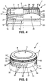
- the cap 1' has a body part 2' with a skirt 15' deprived from the above disclosed top bead 22 and from the above disclosed groove 23.
- the grip part 30, the shape of which is the same as the previously disclosed one, has a flat bottom edge 31 in contact with the bottom side 24 of the bottom bead 21 and a free curved top edge 32 protruding from the outer surface 18 of the skirt 15'.
- the cap 1' according to the variant represented on Figure 4 also differs from the cap 1 previously disclosed in that the ribs 35' are integral with the grip part 30.
- Each rib 35' is molded from the same thermoplastic elastomer as that of the grip part 30 with a bottom end 36' connected to the top edge 32 of the grip part 30, and a top end 37' arranged at a distance from the top wall 5.
- Additional ribs 40 are provided at the outer periphery of the top wall 5.
- the cap 1' For manufacturing the cap 1' according to the variant, molding elements complementary to the grip part 30 and the ribs 35' are used during the molding step. After the molding elements have been removed, the overmolding step is performed to form the grip part 30 and the ribs 35' by means of the lateral nozzle N1 facing the outer surface 18 of the skirt 15.
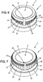
- Figure 5 represents a cap 1" according to a second example which differs from the cap 1 according to the first example previously disclosed in relation to Figure 1 in that the grip part 30 is a regular ring having a flat bottom edge 31 and a flat top edge 32 in contact with the top side 25 of the top bead 22, the top edge 32 of the grip part 30 being spaced apart from the top wall 5.
- Another difference with the first example is the presence of prominent drop-shaped pads 60, on the outer surface of the grip part 30. These prominent drop-shaped pads 60 are useful to improve the grip of the grip part 30.
- the bottom portion 20 of this cap 1" could also be equipped with a temper-proof system as aforedescribed.
- This cap 1" also has annularly dispatched parallel ribs 35 "', similar to the above described ribs (35, 35') of the first embodiment and its variant, located over the top bead 22 and just beneath the shoulder between the skirt 15 and the top wall 5.
- Figure 6 represents a cap 1"'according to a third example which differs from the cap 1 & 1" according to the first & second embodiments previously disclosed in relation to Figure 1 & 2 in the presence of a location member 45 and in the manufacturing method.
- the location member 45 made of the same thermoplastic elastomer as the grip part 30, extends on the outer surface 18 of the skirt 15, parallel to the central axis, from the top edge 32 of one of the narrow portions 34 of the grip part 30, towards the top wall 5. In the illustrated embodiment, an extension of the location member 45 is settled on the outer surface 8 of the top wall 5. The location member 45 may be used to identify an orientation of the cap 1".
- a mold according to a third example having a cavity molding elements and at least one frontal nozzle analogous to that previously disclosed in relation to Figures 2 and 3 can be provided.
- the lateral axis of the at least one lateral nozzle extends parallel to the frontal axis at the vicinity of the outer surface 18 of the skirt 15.
- the lateral nozzle faces the outer surface 8 of the top wall 5.
- the lateral nozzle could extend tangentially to the outer surface 18 of the skirt 15.
- thermoplastic material can be injected through the frontal nozzle Nf for molding the body part 2.
- the thermoplastic elastomer can be injected through the lateral nozzle Nl, in the cavity of the mold in which the boby part 2 remains, for overmolding the grip part 30 onto the outer surface 18 of the skirt and for forming the location member 45.
- the subsequent folding and slitting steps can then be performed.
- a cap 1"" according to a variant of the third example previously disclosed in relation to Figure 5 is represented on Figure 7 .
- the cap 1"" according to a variant of the third example has a general structure identical to that of the cap 1' according to the variant of the first example.
- the grip part 30 of the cap 1"" has a free curved top edge 32 protruding from the outer surface 18 of the skirt 15' and from which ribs 35', integral with the grip part 30, extend. Additional ribs 40 are also provided at the outer periphery 6 of the top wall 5. Reference is made to the above description for further details regarding the other parts of the cap 1"".
- the cap 1"" according to the variant of the third example has the above disclosed location member 45 and can be manufactured according the method disclosed in relation to the manufacture of the cap 1'" according to the third example.
Landscapes
- Engineering & Computer Science (AREA)
- Mechanical Engineering (AREA)
- Manufacturing & Machinery (AREA)
- Closures For Containers (AREA)
Claims (8)
- Kappe (1') zum Verschließen eines Behälters, der ein Halsende umfasst, das eine Öffnung begrenzt, wobei die Kappe (1') sich entlang einer Mittelachse (A) erstreckt und Folgendes umfasst:- einen Körperteil (2'), der aus einem thermoplastischen Material wie etwa einem Polyolefin, vorzugsweise einem Polyethylen (PE) oder einem Polypropylen (PP), besonders bevorzugt aus Polyethylen hoher Dichte (HDPE), geformt ist, wobei der Körperteil (2') eine obere Wand (5) quer zu der Mittelachse (A) und eine Einfassung (15'), die sich um die Mittelachse (A) herum von der oberen Wand (5) zu einem freien Ende (16) hin erstreckt, umfasst, wobei die Einfassung (15') eine Innenfläche (17), die ein Gehäuse (10) zum Aufnehmen des Halsendes des Behälters definiert, und eine der Innenfläche (17) gegenüberliegende Außenfläche (18) aufweist,- einen Greifteil (30), der zumindest teilweise um die Mittelachse (A) herum auf einen Teil des Körperteils (2') aufgeformt ist, aus einem thermoplastischen Elastomer (TPE), wobei das thermoplastische Elastomer weicher als das thermoplastische Material des Körperteils (2') ist, wobei der Greifteil (30) nur auf einen Teil der Außenfläche (18) der Einfassung (15') aufgeformt ist, wobei der Greifteil (30) entlang der Mittelachse (A) durch eine freie Oberkante (32), die in einem Abstand von der oberen Wand (5) angeordnet ist, und eine flache Unterkante (31), die von der Oberkante (32) zum freien Ende (16) der Einfassung (15') hin beabstandet ist, begrenzt ist, wobei der Greifteil (30) eine Mehrzahl von Rippen (35') umfasst, die einstückig damit ausgebildet sind,wobei die Außenfläche (18) der Einfassung (15') über einem unteren Abschnitt (20), der das freie Ende (16) umfasst, einen ringförmigen unteren Wulst (21) um die Mittelachse (A) herum aufweist, wobei der untere Wulst (21) eine flache Unterseite (24) aufweist, wobei die Unterkante (31) des Greifteils (30) von dem freien Ende (16) der Einfassung (15') beabstandet ist, wobei die Unterkante (31) in Kontakt mit der Unterseite (24) des unteren Wulsts (21) steht,
wobei die Kappe (1') dadurch gekennzeichnet ist, dass die Oberkante (32) des Greifteils (30) gekrümmt ist und von der Außenfläche (18) der Einfassung (15') hervorsteht, wobei die Rippen sich parallel zu der Mittelachse (A) auf der Außenfläche (18) der Einfassung (15; 15') zwischen der Oberkante (32) des Greifteils (30) und der oberen Wand (5) erstrecken, wobei die Rippen (35') eine Dicke, radial in Bezug auf die Mittelachse (A) gemessen, aufweisen, die einer Dicke, radial in Bezug auf die Mittelachse (A) gemessen, des unteren Wulsts (21) entspricht. - Kappe (1') nach Anspruch 1, wobei die Außenfläche (18) der Einfassung (15') eine Peripherie um die Mittelachse (A) herum aufweist, wobei der Greifteil (30) sich auf zumindest 30 %, vorzugsweise zumindest 50 % der Peripherie der Außenfläche (18) der Einfassung (15') erstreckt, wobei der Greifteil (30) sich besonders bevorzugt auf der gesamten Peripherie der Außenfläche (18) der Einfassung (15') erstreckt.
- Kappe (1') nach Anspruch 1 oder 2, wobei der Greifteil (30) Griffabschnitte (33) umfasst, die gleichmäßig um die Mittelachse (A) herum verteilt sind.
- Kappe (1') nach Anspruch 3, wobei der Greifteil (30) vergrößerte Abschnitte, welche die Griffabschnitte (33) bilden, und schmalere Abschnitte (34), die zwei benachbarte Griffabschnitte (33) miteinander verbinden, umfasst, sodass vorzugsweise Wellen definiert werden.
- Kappe (1') nach zumindest einem der vorangehenden Ansprüche, wobei der Greifteil (30) in Bezug auf die Einfassung hervorragt, wobei dieses Hervorragen vorzugsweise aus dem Greifteil (30) als Ganzes und/oder aus dem Umstand, dass die Außenfläche des Greifteils (30) einige diskrete Spitzen und/oder Rippen und/oder Felder umfasst, resultiert.
- Verfahren zur Herstellung einer Kappe (1') nach einem der Ansprüche 1 bis 5, das die folgenden Schritte umfasst:- Formen des Körperteils (2') aus einem thermoplastischen Material, wie etwa Polyethylen (PE) oder Polypropylen (PP), vorzugsweise aus Polyethylen hoher Dichte (HDPE), in einem Hohlraum einer Form,- Aufformen des Greifteils (30) zumindest teilweise um die Mittelachse (A) herum nur auf einen Teil der Außenfläche (18) der Einfassung (15') aus einem thermoplastischen Elastomer (TPE) in dem Hohlraum der Form, wobei das thermoplastische Elastomer weicher als das thermoplastische Material des Körperteils (2') ist.
- Verfahren nach Anspruch 6, wobei der Schritt des Formens des Körperteils (2') ein Spritzgießen des thermoplastischen Materials entlang einer Vorderachse koaxial zu der Mittelachse (A) der Kappe (1') durch eine Öffnung einer Vorderdüse (Nf) in den Hohlraum der Form umfasst und der Schritt des Überformens des Greifteils (30) ein Spritzgießen des thermoplastischen Elastomers entlang einer Querachse senkrecht zu der Vorderachse durch eine Öffnung einer Seitendüse (Nl) in den Hohlraum umfasst, um der Außenfläche (18) der Einfassung (15') zugewandt zu sein.
- Verfahren zur Herstellung einer Kappe (1') nach einem der Ansprüche 6 und 7, wobei:- im Schritt des Formens des Körperteils (2') der Hohlraum mit Formelementen versehen wird, die komplementär zu dem Greifteil (30) sind, und- vor dem Schritt des Überformens des Greifteils (30) die Formelemente aus dem Hohlraum entfernt werden.
Priority Applications (1)
| Application Number | Priority Date | Filing Date | Title |
|---|---|---|---|
| PL12818530T PL2938552T3 (pl) | 2012-12-31 | 2012-12-31 | Nakrętka do zamykania pojemnika zawierającego szyjkę ograniczającą otwór i sposób jej wytwarzania |
Applications Claiming Priority (1)
| Application Number | Priority Date | Filing Date | Title |
|---|---|---|---|
| PCT/EP2012/077116 WO2014101973A1 (en) | 2012-12-31 | 2012-12-31 | Cap for closing a container comprising a neck delimiting an opening and method for manufacturing the same |
Publications (2)
| Publication Number | Publication Date |
|---|---|
| EP2938552A1 EP2938552A1 (de) | 2015-11-04 |
| EP2938552B1 true EP2938552B1 (de) | 2019-02-13 |
Family
ID=47603580
Family Applications (1)
| Application Number | Title | Priority Date | Filing Date |
|---|---|---|---|
| EP12818530.3A Active EP2938552B1 (de) | 2012-12-31 | 2012-12-31 | Verschlusskappe eines behälters mit einem hals zur abgrenzung einer öffnung und verfahren zur herstellung davon |
Country Status (11)
| Country | Link |
|---|---|
| US (1) | US10265897B2 (de) |
| EP (1) | EP2938552B1 (de) |
| JP (1) | JP6088662B2 (de) |
| CN (1) | CN105189300B (de) |
| AR (1) | AR096282A1 (de) |
| BR (1) | BR112015015666B1 (de) |
| ES (1) | ES2725561T3 (de) |
| MX (1) | MX365009B (de) |
| PL (1) | PL2938552T3 (de) |
| RU (1) | RU2635793C2 (de) |
| WO (1) | WO2014101973A1 (de) |
Families Citing this family (18)
| Publication number | Priority date | Publication date | Assignee | Title |
|---|---|---|---|---|
| JP1543006S (de) * | 2014-11-25 | 2019-01-21 | ||
| EP3025981B1 (de) * | 2014-11-25 | 2017-09-13 | Tetra Laval Holdings & Finance S.A. | Deckel für eine Öffnungsvorrichtung |
| EP3025982A1 (de) * | 2014-11-25 | 2016-06-01 | Tetra Laval Holdings & Finance S.A. | Deckel für eine Öffnungsvorrichtung |
| GB201501940D0 (en) | 2015-02-05 | 2015-03-25 | Obrist Closures Switzerland | A method of forming a closure |
| USD784132S1 (en) * | 2015-08-03 | 2017-04-18 | William Nevil Heaton Johnson | Interlockable bottle cap |
| USD869274S1 (en) * | 2015-09-11 | 2019-12-10 | Silgan White Cap LLC | Threaded plastic cap |
| USD872577S1 (en) * | 2015-09-11 | 2020-01-14 | Silgan White Cap LLC | Threaded cap |
| USD778160S1 (en) * | 2015-09-21 | 2017-02-07 | Celgene Corporation | Bottle cap |
| DE102016217755A1 (de) * | 2016-09-16 | 2018-03-22 | Henkel Ag & Co. Kgaa | Flasche mit Dosierkappe und Dosierkappe mit flexibler Seitenwand |
| USD791615S1 (en) * | 2016-10-05 | 2017-07-11 | David M Stravitz | Dispenser |
| US10759554B2 (en) * | 2017-02-02 | 2020-09-01 | Rai Strategic Holdings, Inc. | Dispenser unit for aerosol precursor |
| JP6973849B2 (ja) * | 2017-07-14 | 2021-12-01 | 株式会社Csiジャパン | キャップ、閉止装置、および飲料入り閉止装置 |
| USD854927S1 (en) | 2017-07-26 | 2019-07-30 | Drug Plastics & Glass Company, Inc. | Cap |
| US10576702B1 (en) * | 2019-02-04 | 2020-03-03 | Rodney Laible | Method of forming a container insert for use in a closed loop dispensing system |
| CN113784641A (zh) * | 2019-04-10 | 2021-12-10 | 奥古斯特·沃夫博士制药有限及两合公司 | 用于皮肤施用药物和/或化妆品组合物的系统 |
| CN110744202B (zh) * | 2019-11-08 | 2021-09-07 | 大族激光科技产业集团股份有限公司 | 一种防伪防拆封方法及系统 |
| US12454393B2 (en) * | 2020-03-24 | 2025-10-28 | Husky Injection Molding Systems Ltd. | Closure device for a container |
| US20250242367A1 (en) * | 2022-01-18 | 2025-07-31 | Aptar Radolfzell Gmbh | Liquid dispenser |
Citations (1)
| Publication number | Priority date | Publication date | Assignee | Title |
|---|---|---|---|---|
| JP2004196383A (ja) * | 2002-12-20 | 2004-07-15 | Japan Crown Cork Co Ltd | 易開栓型キャップ |
Family Cites Families (22)
| Publication number | Priority date | Publication date | Assignee | Title |
|---|---|---|---|---|
| US2074830A (en) | 1934-11-27 | 1937-03-23 | Colt S Mfg Co | Container closure |
| US2394135A (en) * | 1942-12-24 | 1946-02-05 | Max E Baar | Container closure |
| US4702384A (en) * | 1986-09-10 | 1987-10-27 | Weiser Sylvan W | Screw threaded closure with elastomeric grip band |
| US5443172A (en) * | 1994-09-21 | 1995-08-22 | Gabriele; Joseph F. | Non-slip closure grip for jar lids and the like |
| US6481589B2 (en) * | 2001-02-22 | 2002-11-19 | Seaquist Closures Foreign, Inc. | Non-dispensing closure |
| US7007817B2 (en) * | 2003-09-24 | 2006-03-07 | Berry Plastics Corporation | Container closure |
| US7097790B2 (en) * | 2003-09-24 | 2006-08-29 | Berry Plastics Corporation | Method of producing a container closure |
| US20050145593A1 (en) | 2003-12-30 | 2005-07-07 | Unilever Home & Personal Care Usa | Closure with soft feel grip |
| US20080197101A1 (en) * | 2005-01-13 | 2008-08-21 | Channa Rapoport | Screw Top Closures |
| MX2007013088A (es) * | 2005-04-19 | 2008-03-14 | Ekberg Emballage Ab | Arreglo de tapa. |
| US8109396B1 (en) * | 2006-03-31 | 2012-02-07 | Rexam Healthcare Packaging Inc. | Slide rails and friction surfaces for closure |
| US20080073312A1 (en) * | 2006-09-06 | 2008-03-27 | Alcoa Closure Systems International, Inc. | Composite closure with outer gripping layer |
| US20080302753A1 (en) * | 2007-06-08 | 2008-12-11 | Berry Plastics Corporation | Apparatus and method for producing a container closure |
| FR2921581B1 (fr) * | 2007-09-28 | 2009-11-20 | Alcan Packaging Beauty Serv | Procede et outillage de fabrication d'une piece composite, bouchon composite obtenu par un tel procede ou un tel outillage |
| DE102008010085A1 (de) * | 2008-02-19 | 2009-08-20 | Henkel Ag & Co. Kgaa | Dosierkappe mit optimierten Griffeigenschaften |
| USD586213S1 (en) * | 2008-09-11 | 2009-02-10 | Drug Plastics & Glass Company, Inc. | Bottle cap |
| JP4783866B2 (ja) | 2008-11-21 | 2011-09-28 | 忠一郎 椋木 | ペットボトル用キャップ及びこれを備えたペットボトル、並びに、ペットボトル用キャップのオープナー |
| CN201470549U (zh) * | 2009-08-04 | 2010-05-19 | 张修联 | 一种手把式喷雾器容器 |
| US8231020B2 (en) * | 2010-05-27 | 2012-07-31 | Silgan White Cap LLC | Impact resistant closure |
| PL2720959T3 (pl) * | 2011-06-14 | 2019-05-31 | Closure Systems Int Inc | Zamknięcie |
| US9650179B2 (en) * | 2011-12-15 | 2017-05-16 | Proseries Llc | Cap with overmolded gasket anchoring system |
| USD755633S1 (en) * | 2013-11-18 | 2016-05-10 | Rieke Corporation | Cap |
-
2012
- 2012-12-31 JP JP2015550000A patent/JP6088662B2/ja active Active
- 2012-12-31 RU RU2015131853A patent/RU2635793C2/ru active
- 2012-12-31 MX MX2015008522A patent/MX365009B/es active IP Right Grant
- 2012-12-31 WO PCT/EP2012/077116 patent/WO2014101973A1/en not_active Ceased
- 2012-12-31 EP EP12818530.3A patent/EP2938552B1/de active Active
- 2012-12-31 US US14/758,600 patent/US10265897B2/en active Active
- 2012-12-31 BR BR112015015666-5A patent/BR112015015666B1/pt active IP Right Grant
- 2012-12-31 CN CN201280078079.9A patent/CN105189300B/zh active Active
- 2012-12-31 ES ES12818530T patent/ES2725561T3/es active Active
- 2012-12-31 PL PL12818530T patent/PL2938552T3/pl unknown
-
2013
- 2013-12-27 AR ARP130105030A patent/AR096282A1/es active IP Right Grant
Patent Citations (1)
| Publication number | Priority date | Publication date | Assignee | Title |
|---|---|---|---|---|
| JP2004196383A (ja) * | 2002-12-20 | 2004-07-15 | Japan Crown Cork Co Ltd | 易開栓型キャップ |
Also Published As
| Publication number | Publication date |
|---|---|
| CN105189300B (zh) | 2017-05-31 |
| RU2635793C2 (ru) | 2017-11-15 |
| RU2015131853A (ru) | 2017-02-06 |
| WO2014101973A1 (en) | 2014-07-03 |
| ES2725561T3 (es) | 2019-09-24 |
| JP6088662B2 (ja) | 2017-03-01 |
| US20150336716A1 (en) | 2015-11-26 |
| JP2016506344A (ja) | 2016-03-03 |
| CN105189300A (zh) | 2015-12-23 |
| BR112015015666A2 (pt) | 2017-07-11 |
| US10265897B2 (en) | 2019-04-23 |
| EP2938552A1 (de) | 2015-11-04 |
| AR096282A1 (es) | 2015-12-23 |
| MX2015008522A (es) | 2015-09-10 |
| BR112015015666B1 (pt) | 2021-03-09 |
| PL2938552T3 (pl) | 2019-09-30 |
| MX365009B (es) | 2019-05-20 |
Similar Documents
| Publication | Publication Date | Title |
|---|---|---|
| EP2938552B1 (de) | Verschlusskappe eines behälters mit einem hals zur abgrenzung einer öffnung und verfahren zur herstellung davon | |
| CA2922179C (en) | Lightweight closure with tamper band | |
| EP2709495B1 (de) | Trinkglas und trinkglasanordnung | |
| AU2008258100B2 (en) | Container with low profile cap | |
| EP1361982B1 (de) | Schraubkappe mit integralem griff und integraler dichtung | |
| US9174770B2 (en) | Container with bend resistant grippable dome | |
| EP2927143B1 (de) | Harzgefäss | |
| EP2663505B1 (de) | Kappe für eine getränkeflaschentrinköffnung, satz aus einem deckel und einer solchen kappe für eine getränkeflaschentrinköffnung, trinkvorrichtung und verfahren zur herstellung und vorbereitung einer trinkvorrichtung | |
| EP2653400B1 (de) | Kunststoffbehälter | |
| EP3515834B1 (de) | System mit kappe und behälter und verfahren zur herstellung | |
| WO2015120119A1 (en) | Bowtie hinges | |
| US20190009952A1 (en) | Plastic container with threaded neck finish | |
| EP3515829B1 (de) | Doppelte originalitätsverschlusskappe für einen hals eines behälters, system mit besagter kappe und behälter und verfahren zur herstellung der besagten kappe | |
| US20190308778A1 (en) | Closure | |
| EP1415922B1 (de) | Spritzgiessverfahren zum Herstellen eines Kunststoffbehälters oder Kunststoffverschlusses mit unten umgebördeltem Öffnungsrand | |
| US9187216B2 (en) | Non-metallic wire-cap capsule for an effervescent beverage bottle, and associated closure system | |
| JP6756100B2 (ja) | 合成樹脂製容器 | |
| US20100187262A1 (en) | Blow molded container, dispenser and closure | |
| US20110303682A1 (en) | Heat sterilizable plastic container | |
| US20090139954A1 (en) | Closure With Improved Tamper-Evident Band | |
| JP4382336B2 (ja) | プラスチックキャップ | |
| EP3514075B1 (de) | Aus harz hergestellte flasche | |
| CN209871155U (zh) | 一种塑料瓶用等螺距上盖 | |
| WO2011157393A1 (de) | Saugflasche | |
| CN209871183U (zh) | 一种铝塑盖 |
Legal Events
| Date | Code | Title | Description |
|---|---|---|---|
| PUAI | Public reference made under article 153(3) epc to a published international application that has entered the european phase |
Free format text: ORIGINAL CODE: 0009012 |
|
| 17P | Request for examination filed |
Effective date: 20150710 |
|
| AK | Designated contracting states |
Kind code of ref document: A1 Designated state(s): AL AT BE BG CH CY CZ DE DK EE ES FI FR GB GR HR HU IE IS IT LI LT LU LV MC MK MT NL NO PL PT RO RS SE SI SK SM TR |
|
| AX | Request for extension of the european patent |
Extension state: BA ME |
|
| DAX | Request for extension of the european patent (deleted) | ||
| STAA | Information on the status of an ep patent application or granted ep patent |
Free format text: STATUS: EXAMINATION IS IN PROGRESS |
|
| 17Q | First examination report despatched |
Effective date: 20170313 |
|
| GRAP | Despatch of communication of intention to grant a patent |
Free format text: ORIGINAL CODE: EPIDOSNIGR1 |
|
| STAA | Information on the status of an ep patent application or granted ep patent |
Free format text: STATUS: GRANT OF PATENT IS INTENDED |
|
| INTG | Intention to grant announced |
Effective date: 20180725 |
|
| GRAS | Grant fee paid |
Free format text: ORIGINAL CODE: EPIDOSNIGR3 |
|
| GRAJ | Information related to disapproval of communication of intention to grant by the applicant or resumption of examination proceedings by the epo deleted |
Free format text: ORIGINAL CODE: EPIDOSDIGR1 |
|
| GRAL | Information related to payment of fee for publishing/printing deleted |
Free format text: ORIGINAL CODE: EPIDOSDIGR3 |
|
| STAA | Information on the status of an ep patent application or granted ep patent |
Free format text: STATUS: EXAMINATION IS IN PROGRESS |
|
| INTC | Intention to grant announced (deleted) | ||
| GRAR | Information related to intention to grant a patent recorded |
Free format text: ORIGINAL CODE: EPIDOSNIGR71 |
|
| STAA | Information on the status of an ep patent application or granted ep patent |
Free format text: STATUS: GRANT OF PATENT IS INTENDED |
|
| GRAA | (expected) grant |
Free format text: ORIGINAL CODE: 0009210 |
|
| STAA | Information on the status of an ep patent application or granted ep patent |
Free format text: STATUS: THE PATENT HAS BEEN GRANTED |
|
| INTG | Intention to grant announced |
Effective date: 20190103 |
|
| AK | Designated contracting states |
Kind code of ref document: B1 Designated state(s): AL AT BE BG CH CY CZ DE DK EE ES FI FR GB GR HR HU IE IS IT LI LT LU LV MC MK MT NL NO PL PT RO RS SE SI SK SM TR |
|
| REG | Reference to a national code |
Ref country code: GB Ref legal event code: FG4D |
|
| REG | Reference to a national code |
Ref country code: CH Ref legal event code: EP Ref country code: AT Ref legal event code: REF Ref document number: 1096065 Country of ref document: AT Kind code of ref document: T Effective date: 20190215 |
|
| REG | Reference to a national code |
Ref country code: IE Ref legal event code: FG4D |
|
| REG | Reference to a national code |
Ref country code: DE Ref legal event code: R096 Ref document number: 602012056688 Country of ref document: DE |
|
| REG | Reference to a national code |
Ref country code: CH Ref legal event code: NV Representative=s name: VALIPAT S.A. GEVERS SA, CH |
|
| REG | Reference to a national code |
Ref country code: NL Ref legal event code: FP |
|
| REG | Reference to a national code |
Ref country code: LT Ref legal event code: MG4D |
|
| PG25 | Lapsed in a contracting state [announced via postgrant information from national office to epo] |
Ref country code: LT Free format text: LAPSE BECAUSE OF FAILURE TO SUBMIT A TRANSLATION OF THE DESCRIPTION OR TO PAY THE FEE WITHIN THE PRESCRIBED TIME-LIMIT Effective date: 20190213 Ref country code: NO Free format text: LAPSE BECAUSE OF FAILURE TO SUBMIT A TRANSLATION OF THE DESCRIPTION OR TO PAY THE FEE WITHIN THE PRESCRIBED TIME-LIMIT Effective date: 20190513 Ref country code: PT Free format text: LAPSE BECAUSE OF FAILURE TO SUBMIT A TRANSLATION OF THE DESCRIPTION OR TO PAY THE FEE WITHIN THE PRESCRIBED TIME-LIMIT Effective date: 20190613 Ref country code: FI Free format text: LAPSE BECAUSE OF FAILURE TO SUBMIT A TRANSLATION OF THE DESCRIPTION OR TO PAY THE FEE WITHIN THE PRESCRIBED TIME-LIMIT Effective date: 20190213 Ref country code: SE Free format text: LAPSE BECAUSE OF FAILURE TO SUBMIT A TRANSLATION OF THE DESCRIPTION OR TO PAY THE FEE WITHIN THE PRESCRIBED TIME-LIMIT Effective date: 20190213 |
|
| PG25 | Lapsed in a contracting state [announced via postgrant information from national office to epo] |
Ref country code: HR Free format text: LAPSE BECAUSE OF FAILURE TO SUBMIT A TRANSLATION OF THE DESCRIPTION OR TO PAY THE FEE WITHIN THE PRESCRIBED TIME-LIMIT Effective date: 20190213 Ref country code: RS Free format text: LAPSE BECAUSE OF FAILURE TO SUBMIT A TRANSLATION OF THE DESCRIPTION OR TO PAY THE FEE WITHIN THE PRESCRIBED TIME-LIMIT Effective date: 20190213 Ref country code: IS Free format text: LAPSE BECAUSE OF FAILURE TO SUBMIT A TRANSLATION OF THE DESCRIPTION OR TO PAY THE FEE WITHIN THE PRESCRIBED TIME-LIMIT Effective date: 20190613 Ref country code: GR Free format text: LAPSE BECAUSE OF FAILURE TO SUBMIT A TRANSLATION OF THE DESCRIPTION OR TO PAY THE FEE WITHIN THE PRESCRIBED TIME-LIMIT Effective date: 20190514 Ref country code: LV Free format text: LAPSE BECAUSE OF FAILURE TO SUBMIT A TRANSLATION OF THE DESCRIPTION OR TO PAY THE FEE WITHIN THE PRESCRIBED TIME-LIMIT Effective date: 20190213 Ref country code: BG Free format text: LAPSE BECAUSE OF FAILURE TO SUBMIT A TRANSLATION OF THE DESCRIPTION OR TO PAY THE FEE WITHIN THE PRESCRIBED TIME-LIMIT Effective date: 20190513 |
|
| REG | Reference to a national code |
Ref country code: AT Ref legal event code: MK05 Ref document number: 1096065 Country of ref document: AT Kind code of ref document: T Effective date: 20190213 |
|
| REG | Reference to a national code |
Ref country code: ES Ref legal event code: FG2A Ref document number: 2725561 Country of ref document: ES Kind code of ref document: T3 Effective date: 20190924 |
|
| PG25 | Lapsed in a contracting state [announced via postgrant information from national office to epo] |
Ref country code: EE Free format text: LAPSE BECAUSE OF FAILURE TO SUBMIT A TRANSLATION OF THE DESCRIPTION OR TO PAY THE FEE WITHIN THE PRESCRIBED TIME-LIMIT Effective date: 20190213 Ref country code: SK Free format text: LAPSE BECAUSE OF FAILURE TO SUBMIT A TRANSLATION OF THE DESCRIPTION OR TO PAY THE FEE WITHIN THE PRESCRIBED TIME-LIMIT Effective date: 20190213 Ref country code: CZ Free format text: LAPSE BECAUSE OF FAILURE TO SUBMIT A TRANSLATION OF THE DESCRIPTION OR TO PAY THE FEE WITHIN THE PRESCRIBED TIME-LIMIT Effective date: 20190213 Ref country code: RO Free format text: LAPSE BECAUSE OF FAILURE TO SUBMIT A TRANSLATION OF THE DESCRIPTION OR TO PAY THE FEE WITHIN THE PRESCRIBED TIME-LIMIT Effective date: 20190213 Ref country code: AL Free format text: LAPSE BECAUSE OF FAILURE TO SUBMIT A TRANSLATION OF THE DESCRIPTION OR TO PAY THE FEE WITHIN THE PRESCRIBED TIME-LIMIT Effective date: 20190213 Ref country code: IT Free format text: LAPSE BECAUSE OF FAILURE TO SUBMIT A TRANSLATION OF THE DESCRIPTION OR TO PAY THE FEE WITHIN THE PRESCRIBED TIME-LIMIT Effective date: 20190213 Ref country code: DK Free format text: LAPSE BECAUSE OF FAILURE TO SUBMIT A TRANSLATION OF THE DESCRIPTION OR TO PAY THE FEE WITHIN THE PRESCRIBED TIME-LIMIT Effective date: 20190213 |
|
| REG | Reference to a national code |
Ref country code: DE Ref legal event code: R097 Ref document number: 602012056688 Country of ref document: DE |
|
| PG25 | Lapsed in a contracting state [announced via postgrant information from national office to epo] |
Ref country code: SM Free format text: LAPSE BECAUSE OF FAILURE TO SUBMIT A TRANSLATION OF THE DESCRIPTION OR TO PAY THE FEE WITHIN THE PRESCRIBED TIME-LIMIT Effective date: 20190213 |
|
| PLBE | No opposition filed within time limit |
Free format text: ORIGINAL CODE: 0009261 |
|
| STAA | Information on the status of an ep patent application or granted ep patent |
Free format text: STATUS: NO OPPOSITION FILED WITHIN TIME LIMIT |
|
| PG25 | Lapsed in a contracting state [announced via postgrant information from national office to epo] |
Ref country code: AT Free format text: LAPSE BECAUSE OF FAILURE TO SUBMIT A TRANSLATION OF THE DESCRIPTION OR TO PAY THE FEE WITHIN THE PRESCRIBED TIME-LIMIT Effective date: 20190213 |
|
| 26N | No opposition filed |
Effective date: 20191114 |
|
| PG25 | Lapsed in a contracting state [announced via postgrant information from national office to epo] |
Ref country code: SI Free format text: LAPSE BECAUSE OF FAILURE TO SUBMIT A TRANSLATION OF THE DESCRIPTION OR TO PAY THE FEE WITHIN THE PRESCRIBED TIME-LIMIT Effective date: 20190213 |
|
| PG25 | Lapsed in a contracting state [announced via postgrant information from national office to epo] |
Ref country code: MC Free format text: LAPSE BECAUSE OF FAILURE TO SUBMIT A TRANSLATION OF THE DESCRIPTION OR TO PAY THE FEE WITHIN THE PRESCRIBED TIME-LIMIT Effective date: 20190213 |
|
| PG25 | Lapsed in a contracting state [announced via postgrant information from national office to epo] |
Ref country code: LU Free format text: LAPSE BECAUSE OF NON-PAYMENT OF DUE FEES Effective date: 20191231 Ref country code: IE Free format text: LAPSE BECAUSE OF NON-PAYMENT OF DUE FEES Effective date: 20191231 |
|
| PG25 | Lapsed in a contracting state [announced via postgrant information from national office to epo] |
Ref country code: CY Free format text: LAPSE BECAUSE OF FAILURE TO SUBMIT A TRANSLATION OF THE DESCRIPTION OR TO PAY THE FEE WITHIN THE PRESCRIBED TIME-LIMIT Effective date: 20190213 |
|
| PG25 | Lapsed in a contracting state [announced via postgrant information from national office to epo] |
Ref country code: MT Free format text: LAPSE BECAUSE OF FAILURE TO SUBMIT A TRANSLATION OF THE DESCRIPTION OR TO PAY THE FEE WITHIN THE PRESCRIBED TIME-LIMIT Effective date: 20190213 Ref country code: HU Free format text: LAPSE BECAUSE OF FAILURE TO SUBMIT A TRANSLATION OF THE DESCRIPTION OR TO PAY THE FEE WITHIN THE PRESCRIBED TIME-LIMIT; INVALID AB INITIO Effective date: 20121231 |
|
| PG25 | Lapsed in a contracting state [announced via postgrant information from national office to epo] |
Ref country code: MK Free format text: LAPSE BECAUSE OF FAILURE TO SUBMIT A TRANSLATION OF THE DESCRIPTION OR TO PAY THE FEE WITHIN THE PRESCRIBED TIME-LIMIT Effective date: 20190213 |
|
| P01 | Opt-out of the competence of the unified patent court (upc) registered |
Effective date: 20230526 |
|
| PGFP | Annual fee paid to national office [announced via postgrant information from national office to epo] |
Ref country code: NL Payment date: 20251127 Year of fee payment: 14 |
|
| REG | Reference to a national code |
Ref country code: CH Ref legal event code: U11 Free format text: ST27 STATUS EVENT CODE: U-0-0-U10-U11 (AS PROVIDED BY THE NATIONAL OFFICE) Effective date: 20260101 |
|
| PGFP | Annual fee paid to national office [announced via postgrant information from national office to epo] |
Ref country code: GB Payment date: 20251229 Year of fee payment: 14 |
|
| PGFP | Annual fee paid to national office [announced via postgrant information from national office to epo] |
Ref country code: FR Payment date: 20251121 Year of fee payment: 14 |
|
| PGFP | Annual fee paid to national office [announced via postgrant information from national office to epo] |
Ref country code: TR Payment date: 20251219 Year of fee payment: 14 Ref country code: BE Payment date: 20251226 Year of fee payment: 14 |
|
| PGFP | Annual fee paid to national office [announced via postgrant information from national office to epo] |
Ref country code: PL Payment date: 20251125 Year of fee payment: 14 |
|
| PGFP | Annual fee paid to national office [announced via postgrant information from national office to epo] |
Ref country code: ES Payment date: 20260112 Year of fee payment: 14 |
|
| PGFP | Annual fee paid to national office [announced via postgrant information from national office to epo] |
Ref country code: DE Payment date: 20251231 Year of fee payment: 14 |
|
| PGFP | Annual fee paid to national office [announced via postgrant information from national office to epo] |
Ref country code: CH Payment date: 20260101 Year of fee payment: 14 |