EP3774566B1 - Verschluss - Google Patents
Verschluss Download PDFInfo
- Publication number
- EP3774566B1 EP3774566B1 EP19784812.0A EP19784812A EP3774566B1 EP 3774566 B1 EP3774566 B1 EP 3774566B1 EP 19784812 A EP19784812 A EP 19784812A EP 3774566 B1 EP3774566 B1 EP 3774566B1
- Authority
- EP
- European Patent Office
- Prior art keywords
- skin layer
- brim
- aperture
- closure
- extends
- Prior art date
- Legal status (The legal status is an assumption and is not a legal conclusion. Google has not performed a legal analysis and makes no representation as to the accuracy of the status listed.)
- Active
Links
Images

Classifications
-
- B—PERFORMING OPERATIONS; TRANSPORTING
- B65—CONVEYING; PACKING; STORING; HANDLING THIN OR FILAMENTARY MATERIAL
- B65D—CONTAINERS FOR STORAGE OR TRANSPORT OF ARTICLES OR MATERIALS, e.g. BAGS, BARRELS, BOTTLES, BOXES, CANS, CARTONS, CRATES, DRUMS, JARS, TANKS, HOPPERS, FORWARDING CONTAINERS; ACCESSORIES, CLOSURES, OR FITTINGS THEREFOR; PACKAGING ELEMENTS; PACKAGES
- B65D41/00—Caps, e.g. crown caps or crown seals, i.e. members having parts arranged for engagement with the external periphery of a neck or wall defining a pouring opening or discharge aperture; Protective cap-like covers for closure members, e.g. decorative covers of metal foil or paper
- B65D41/02—Caps or cap-like covers without lines of weakness, tearing strips, tags, or like opening or removal devices
- B65D41/04—Threaded or like caps or cap-like covers secured by rotation
- B65D41/0485—Threaded or like caps or cap-like covers secured by rotation with means specially adapted for facilitating the operation of opening or closing
-
- B—PERFORMING OPERATIONS; TRANSPORTING
- B29—WORKING OF PLASTICS; WORKING OF SUBSTANCES IN A PLASTIC STATE IN GENERAL
- B29C—SHAPING OR JOINING OF PLASTICS; SHAPING OF MATERIAL IN A PLASTIC STATE, NOT OTHERWISE PROVIDED FOR; AFTER-TREATMENT OF THE SHAPED PRODUCTS, e.g. REPAIRING
- B29C45/00—Injection moulding, i.e. forcing the required volume of moulding material through a nozzle into a closed mould; Apparatus therefor
- B29C45/16—Making multilayered or multicoloured articles
- B29C45/1676—Making multilayered or multicoloured articles using a soft material and a rigid material, e.g. making articles with a sealing part
-
- B—PERFORMING OPERATIONS; TRANSPORTING
- B29—WORKING OF PLASTICS; WORKING OF SUBSTANCES IN A PLASTIC STATE IN GENERAL
- B29C—SHAPING OR JOINING OF PLASTICS; SHAPING OF MATERIAL IN A PLASTIC STATE, NOT OTHERWISE PROVIDED FOR; AFTER-TREATMENT OF THE SHAPED PRODUCTS, e.g. REPAIRING
- B29C37/00—Component parts, details, accessories or auxiliary operations, not covered by group B29C33/00 or B29C35/00
- B29C37/0078—Measures or configurations for obtaining anchoring effects in the contact areas between layers
- B29C37/0082—Mechanical anchoring
- B29C37/0085—Mechanical anchoring by means of openings in the layers
-
- B—PERFORMING OPERATIONS; TRANSPORTING
- B65—CONVEYING; PACKING; STORING; HANDLING THIN OR FILAMENTARY MATERIAL
- B65D—CONTAINERS FOR STORAGE OR TRANSPORT OF ARTICLES OR MATERIALS, e.g. BAGS, BARRELS, BOTTLES, BOXES, CANS, CARTONS, CRATES, DRUMS, JARS, TANKS, HOPPERS, FORWARDING CONTAINERS; ACCESSORIES, CLOSURES, OR FITTINGS THEREFOR; PACKAGING ELEMENTS; PACKAGES
- B65D43/00—Lids or covers for rigid or semi-rigid containers
- B65D43/02—Removable lids or covers
- B65D43/0202—Removable lids or covers without integral tamper element
- B65D43/0225—Removable lids or covers without integral tamper element secured by rotation
- B65D43/0231—Removable lids or covers without integral tamper element secured by rotation only on the outside, or a part turned to the outside, of the mouth of the container
-
- B—PERFORMING OPERATIONS; TRANSPORTING
- B65—CONVEYING; PACKING; STORING; HANDLING THIN OR FILAMENTARY MATERIAL
- B65D—CONTAINERS FOR STORAGE OR TRANSPORT OF ARTICLES OR MATERIALS, e.g. BAGS, BARRELS, BOTTLES, BOXES, CANS, CARTONS, CRATES, DRUMS, JARS, TANKS, HOPPERS, FORWARDING CONTAINERS; ACCESSORIES, CLOSURES, OR FITTINGS THEREFOR; PACKAGING ELEMENTS; PACKAGES
- B65D50/00—Closures with means for discouraging unauthorised opening or removal thereof, with or without indicating means, e.g. child-proof closures
- B65D50/02—Closures with means for discouraging unauthorised opening or removal thereof, with or without indicating means, e.g. child-proof closures openable or removable by the combination of plural actions
- B65D50/04—Closures with means for discouraging unauthorised opening or removal thereof, with or without indicating means, e.g. child-proof closures openable or removable by the combination of plural actions requiring the combination of simultaneous actions, e.g. depressing and turning, lifting and turning, maintaining a part and turning another one
- B65D50/041—Closures with means for discouraging unauthorised opening or removal thereof, with or without indicating means, e.g. child-proof closures openable or removable by the combination of plural actions requiring the combination of simultaneous actions, e.g. depressing and turning, lifting and turning, maintaining a part and turning another one the closure comprising nested inner and outer caps or an inner cap and an outer coaxial annular member, which can be brought into engagement to enable removal by rotation
-
- B—PERFORMING OPERATIONS; TRANSPORTING
- B65—CONVEYING; PACKING; STORING; HANDLING THIN OR FILAMENTARY MATERIAL
- B65D—CONTAINERS FOR STORAGE OR TRANSPORT OF ARTICLES OR MATERIALS, e.g. BAGS, BARRELS, BOTTLES, BOXES, CANS, CARTONS, CRATES, DRUMS, JARS, TANKS, HOPPERS, FORWARDING CONTAINERS; ACCESSORIES, CLOSURES, OR FITTINGS THEREFOR; PACKAGING ELEMENTS; PACKAGES
- B65D51/00—Closures not otherwise provided for
- B65D51/16—Closures not otherwise provided for with means for venting air or gas
-
- B—PERFORMING OPERATIONS; TRANSPORTING
- B29—WORKING OF PLASTICS; WORKING OF SUBSTANCES IN A PLASTIC STATE IN GENERAL
- B29C—SHAPING OR JOINING OF PLASTICS; SHAPING OF MATERIAL IN A PLASTIC STATE, NOT OTHERWISE PROVIDED FOR; AFTER-TREATMENT OF THE SHAPED PRODUCTS, e.g. REPAIRING
- B29C45/00—Injection moulding, i.e. forcing the required volume of moulding material through a nozzle into a closed mould; Apparatus therefor
- B29C45/16—Making multilayered or multicoloured articles
- B29C2045/1682—Making multilayered or multicoloured articles preventing defects
-
- B—PERFORMING OPERATIONS; TRANSPORTING
- B29—WORKING OF PLASTICS; WORKING OF SUBSTANCES IN A PLASTIC STATE IN GENERAL
- B29C—SHAPING OR JOINING OF PLASTICS; SHAPING OF MATERIAL IN A PLASTIC STATE, NOT OTHERWISE PROVIDED FOR; AFTER-TREATMENT OF THE SHAPED PRODUCTS, e.g. REPAIRING
- B29C45/00—Injection moulding, i.e. forcing the required volume of moulding material through a nozzle into a closed mould; Apparatus therefor
- B29C45/16—Making multilayered or multicoloured articles
-
- B—PERFORMING OPERATIONS; TRANSPORTING
- B29—WORKING OF PLASTICS; WORKING OF SUBSTANCES IN A PLASTIC STATE IN GENERAL
- B29K—INDEXING SCHEME ASSOCIATED WITH SUBCLASSES B29B, B29C OR B29D, RELATING TO MOULDING MATERIALS OR TO MATERIALS FOR MOULDS, REINFORCEMENTS, FILLERS OR PREFORMED PARTS, e.g. INSERTS
- B29K2021/00—Use of unspecified rubbers as moulding material
- B29K2021/003—Thermoplastic elastomers
-
- B—PERFORMING OPERATIONS; TRANSPORTING
- B29—WORKING OF PLASTICS; WORKING OF SUBSTANCES IN A PLASTIC STATE IN GENERAL
- B29K—INDEXING SCHEME ASSOCIATED WITH SUBCLASSES B29B, B29C OR B29D, RELATING TO MOULDING MATERIALS OR TO MATERIALS FOR MOULDS, REINFORCEMENTS, FILLERS OR PREFORMED PARTS, e.g. INSERTS
- B29K2023/00—Use of polyalkenes or derivatives thereof as moulding material
- B29K2023/04—Polymers of ethylene
- B29K2023/06—PE, i.e. polyethylene
-
- B—PERFORMING OPERATIONS; TRANSPORTING
- B29—WORKING OF PLASTICS; WORKING OF SUBSTANCES IN A PLASTIC STATE IN GENERAL
- B29K—INDEXING SCHEME ASSOCIATED WITH SUBCLASSES B29B, B29C OR B29D, RELATING TO MOULDING MATERIALS OR TO MATERIALS FOR MOULDS, REINFORCEMENTS, FILLERS OR PREFORMED PARTS, e.g. INSERTS
- B29K2023/00—Use of polyalkenes or derivatives thereof as moulding material
- B29K2023/10—Polymers of propylene
- B29K2023/12—PP, i.e. polypropylene
-
- B—PERFORMING OPERATIONS; TRANSPORTING
- B29—WORKING OF PLASTICS; WORKING OF SUBSTANCES IN A PLASTIC STATE IN GENERAL
- B29L—INDEXING SCHEME ASSOCIATED WITH SUBCLASS B29C, RELATING TO PARTICULAR ARTICLES
- B29L2031/00—Other particular articles
- B29L2031/56—Stoppers or lids for bottles, jars, or the like, e.g. closures
- B29L2031/565—Stoppers or lids for bottles, jars, or the like, e.g. closures for containers
-
- B—PERFORMING OPERATIONS; TRANSPORTING
- B65—CONVEYING; PACKING; STORING; HANDLING THIN OR FILAMENTARY MATERIAL
- B65D—CONTAINERS FOR STORAGE OR TRANSPORT OF ARTICLES OR MATERIALS, e.g. BAGS, BARRELS, BOTTLES, BOXES, CANS, CARTONS, CRATES, DRUMS, JARS, TANKS, HOPPERS, FORWARDING CONTAINERS; ACCESSORIES, CLOSURES, OR FITTINGS THEREFOR; PACKAGING ELEMENTS; PACKAGES
- B65D2251/00—Details relating to container closures
- B65D2251/02—Grip means
- B65D2251/026—Grip means made of material having a high friction coefficient and preventing slippage during removal by hand, e.g. band, coating
-
- B—PERFORMING OPERATIONS; TRANSPORTING
- B65—CONVEYING; PACKING; STORING; HANDLING THIN OR FILAMENTARY MATERIAL
- B65D—CONTAINERS FOR STORAGE OR TRANSPORT OF ARTICLES OR MATERIALS, e.g. BAGS, BARRELS, BOTTLES, BOXES, CANS, CARTONS, CRATES, DRUMS, JARS, TANKS, HOPPERS, FORWARDING CONTAINERS; ACCESSORIES, CLOSURES, OR FITTINGS THEREFOR; PACKAGING ELEMENTS; PACKAGES
- B65D2543/00—Lids or covers essentially for box-like containers
- B65D2543/00009—Details of lids or covers for rigid or semi-rigid containers
- B65D2543/00018—Overall construction of the lid
- B65D2543/00259—Materials used
- B65D2543/00296—Plastic
-
- B—PERFORMING OPERATIONS; TRANSPORTING
- B65—CONVEYING; PACKING; STORING; HANDLING THIN OR FILAMENTARY MATERIAL
- B65D—CONTAINERS FOR STORAGE OR TRANSPORT OF ARTICLES OR MATERIALS, e.g. BAGS, BARRELS, BOTTLES, BOXES, CANS, CARTONS, CRATES, DRUMS, JARS, TANKS, HOPPERS, FORWARDING CONTAINERS; ACCESSORIES, CLOSURES, OR FITTINGS THEREFOR; PACKAGING ELEMENTS; PACKAGES
- B65D2543/00—Lids or covers essentially for box-like containers
- B65D2543/00009—Details of lids or covers for rigid or semi-rigid containers
- B65D2543/00824—Means for facilitating removing of the closure
- B65D2543/00861—Non-integral tabs, tongues, handles or similar
Definitions
- the present disclosure relates to closures, and particularly to removable closures. More particularly, the present disclosure relates to closures made from plastics materials.
- WO 2015/195516 A1 discloses a cap with an overmolded gasket anchoring system, for an ice bag.
- the ice bag is described as having a bladder formed with an opening, a threaded receiver coupled to the bladder at the opening, a threaded cap having a first portion formed of a rigid material and a second portion formed of an overmold material, the second portion providing a seal between the receiver and cap with the cap threaded into the receiver.
- WO 2008/030400 A2 disclosing the preamble of claim 1, shows a composite closure for an associated container configured to facilitate gripping and manipulation by consumers, as well as handling of closures by automated equipment.
- a canister includes a closure and a container.
- the container is formed to include a product-receiving chamber therein.
- the closure is configured to mount to the container to block selectively access to the product-receiving chamber through an open mouth formed in the container.
- the closure includes a lid and a skin layer coupled to an outer surface of the lid.
- the lid is rigid and the skin layer is made of relatively soft materials to provide a comfortable grip interface for a user grasping the closure.
- the lid may include polypropylene or polyethylene and the skin layer may include rubber.
- the skin layer is arranged to cover at least a portion of the lid and it may cover most of or the entire outer surface of the lid.
- the closure is formed by overmolding the skin layer onto the lid.
- the lid is formed to include vent apertures that are configured to receive gases and/or excess skin layer materials during the overmolding process to minimize flashing of the skin layer.
- the lid includes a top wall, a side wall coupled to a perimeter of the top wall and arranged to extend downwardly from the top wall, and a brim coupled to an end of the side wall.
- the top wall and the side wall define an outer surface of the lid.
- the skin layer is overmolded onto the outer surface of the lid such that at least a portion of the lid is covered by the skin layer.
- the brim of the lid includes an outer surface and an inner surface.
- the brim is formed to include a vent aperture that extends into the brim from the outer surface toward the inner surface.
- the vent aperture extends through the outer surface and the inner surface.
- the vent aperture extends from the outer surface partway into the brim toward the inner surface.
- FIG. 1-5 A first embodiment of a closure 14 in accordance with the present disclosure is shown in Figs. 1-5 .
- a second embodiment of a closure 214 is shown in Figs. 6 and 7 .
- a third embodiment of a closure 314 is shown in Fig. 8 .
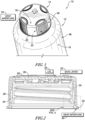
- Closures 14, 214, 314 are adapted to mate with a container 12 included in a canister 10 as suggested, for example, in Fig. 1 .
- Closure 14 includes a lid 20 and a skin layer 22 arranged to cover at least a portion of an outer surface 29 of lid 20 as shown in Figs. 1 and 2 .
- Skin layer 22 provides a soft grip interface for users grasping closure 14 to separate or mate closure 14 and container 12.
- Lid 20 is formed to include a plurality of discrete vent apertures 34 as shown in Figs. 1, 2 , and 4 .
- lid 20 includes a single continuous vent aperture 234 as shown in Figs. 6 and 7 .
- Vent apertures 34 are configured to allow gases and portions of skin layer 22 to flow into vent apertures 34 during manufacture of closure 14 so that flashing of skin layer 22 during the manufacturing process is minimized.
- skin layer 22 is overmolded onto lid 20 and vent apertures 34 allow excess skin layer material to be received in vent apertures 34 instead of flashing about a brim 32 of lid 20 during the overmolding process.
- Container 12 includes, for example, a filler neck 36 and a body 38, as shown in Fig. 1 .
- Filler neck 36 cooperates with body 38 to define a product receiving chamber 18 therein.
- An open mouth 16 is formed in filler neck 36 and arranged to open into product receiving chamber 18 to allow communication with product receiving chamber 18 through open mouth 16.
- Closure 14 is configured to mount selectively on filler neck 36 of container 12 via complementary threads included in container 12 and closure 14 to cover open mouth 16 as suggested in Fig. 1 .
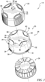
- Container 12 and closure 14 share a common central axis 15 in a radially central location to container 12 and closure 14 as shown in Fig. 3 .
- Closure 14 includes lid 20 and skin layer 22 configured to provide a soft grip interface for a user grasping closure 14 as shown in Fig. 2 .
- Lid 20 directly engages filler neck 36 of container 12 to cover open mouth 16 and block access to chamber 18.
- Skin layer 22 is overmolded onto lid 20 during manufacture of closure 14 such that at least a portion of lid 20 is covered by skin layer 22 and another portion of lid 20 is not covered by skin layer 22.
- lid 20 and skin layer 22 are formed from plastics materials.
- Lid 20 is made to be rigid.
- lid 20 includes polypropylene materials.
- lid 20 includes polyethylene materials.
- Skin layer 22 is formed from materials that are different from the materials of lid 20. Skin layer 22 may include any suitable material such as, for example, thermoplastic elastomer materials, thermoplastic olefin materials, polypropylene, polyethylene, or any other suitable materials to provide a comfortable grip interface for a user.
- Lid 20 includes a top wall 28, a side wall 30 coupled to top wall 28, and a brim 32 coupled to side wall 30 as shown in Fig. 2 .
- Top wall 28 is arranged generally perpendicular to central axis 15 and cooperates with side wall 30 to define outer surface 29 of lid 20.
- Side wall 30 extends axially downward away from top wall 28 toward container 12.
- Brim 32 is coupled to a distal end of side wall 30 and is spaced apart from top wall 28.
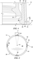
- Brim 32 is formed to include a plurality of vent apertures 34 configured to receive the flow of gases and the portion of skin layer 22 during manufacture of closure 14 so that flashing of skin layer 22 is minimized. Vent apertures 34 extend downwardly into brim 32 toward container 12 and open upwardly toward top wall 28.
- Brim 32 extends radially outward from side wall 30 and includes an upper surface 42 and a lower surface 44 as shown in Fig. 4 .
- Upper surface 42 faces upwardly toward top wall 28.
- Lower surface 44 faces downwardly toward container 12.
- vent aperture 34 extends through upper surface 42 and lower surface 44 of brim 32 as shown in Fig. 4 . Gases may flow from upper surface 42, through vent aperture 34, and past lower surface 44 as skin layer 22 is molded onto lid 20.
- skin layer 22 is configured to flow into vent aperture 34 such that an end 48 of skin layer 22 stops at a point 46 between upper surface 42 and lower surface 44 and between side wall 30 and brim 32. That is, skin layer 22 does not extend downwardly beyond lower surface 44 of brim 32. In other embodiments, end 48 of skin layer 22 may rest at any point before, between, or beyond upper surface 42 or lower surface 44 of brim 32.
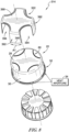
- brim 32 is formed to include a plurality of vent apertures 34 as shown by the bottom view of outer cap 26 of lid 20 in Fig. 5 .
- the vent apertures 34 are spaced apart from one another circumferentially relative to a perimeter 50 of brim 32.
- brim 32 is formed to include first, second, third, and fourth vent apertures 52, 54, 56, 58 spaced apart from one another circumferentially around perimeter 50.
- Each vent aperture is spaced apart from a neighboring vent aperture 34 by an angle. The angle is about 90 degrees in the illustrative embodiment such that each vent aperture 34 is equally spaced from neighboring vent apertures 34.
- the vent apertures may not be space equally from one another.
- each vent aperture 34 is discrete and configured to extend partway around perimeter 50 of brim 32 by an angle ⁇ as shown in Fig. 5 .
- the angle ⁇ is about 20 degrees. In some embodiments, the angle ⁇ is less than 360 degrees. In some embodiments, the angle ⁇ is less than about 180 degrees. In some embodiments, the angle ⁇ is less than about 90 degrees. In some embodiments, the angle ⁇ is less than about 45 degrees.
- the angle ⁇ is between about 5 and about 30 degrees. In some embodiments, the angle ⁇ is between about 10 and about 25 degrees. In some embodiments, the angle ⁇ is between about 15 and about 25 degrees.
- Lid 20 further includes slide rails 60 coupled to top wall 28 and arranged to extend upwardly from top wall 28 away from container 12 as shown in Fig. 2 and 3 .
- Skin layer 22 is formed to include slide-rail apertures 76 sized and shaped to receive slide rails 60 when skin layer 22 is overmolded onto lid 20. Skin layer 22 is overmolded onto lid 20 such that slide rails 60 of lid 20 extend through skin layer 22. Slide rails 60 have a lower coefficient of friction than skin layer 22.
- Slide rails 60 extend beyond skin layer 22 and allow closure 14 to slide on surfaces when closure 14 is upside-down and supported on the surfaces by slide rails 60.
- Skin layer 22 does not extend downwardly beyond lower surface 44 of brim 32 in the illustrative embodiments so that brim 32 supports closure 14 on surfaces when closure is right-side up to allow closure 14 to slide on the surfaces.
- closure 14 includes a first, second, third, and fourth slide rail 62, 64, 66, 68 as shown in Fig. 3 .
- Each of slide rails 62, 64, 66, 68 is spaced apart from neighboring slide rails 62, 64, 66, 68 about equal distances circumferentially around a perimeter 70 of top wall 28.
- slide rails 62, 64, 66, 68 may not be spaces apart equally around perimeter 70.
- Skin layer 22 is formed to include complementary slide rail apertures 82, 84, 86, 88 that receive respective slide rails 62, 64, 66, 68.
- Each of slide rails 62, 64, 66, 68 have a curvilinear shape and are convex relative to central axis 15 as shown in Fig. 3 .
- Each slide rail 62, 64, 66, 68 has a first end 72 and a second end 74, both of which are arranged adjacent to perimeter 70 of top wall 28.
- Slide rails 62, 64, 66, 68 also have a midsection 75 that extends radially inward in an arc from ends 72, 74 toward central axis 15 to define the curvilinear shape of slide rails 62, 64, 66, 68.
- slide rails 62, 64, 66, 68 extend radially outward from axis 15.
- the slide rails may have any other suitable shape in other embodiments.
- lid 20 includes an inner cap 24 configured to engage filler neck 36 and an outer cap 26 arranged to overlay inner cap 24 as shown in Fig. 3 .
- Outer cap 26 floats relative to inner cap 24 to provide a resistant lock for closure 14.
- Closure 14 may be removed from filler neck 36 by moving outer cap 26 toward inner cap 24 such that a plurality of teeth formed in outer cap 26 interlock with a plurality of teeth formed in inner cap 24 and twisting outer cap 26 and the inner cap via the interlocked teeth.
- lid 20 may not include an inner cap and may directly engage filler neck 36 of container 12.
- a method of providing or manufacturing closure 14 includes a number of steps.
- the method includes molding lid 20 to include top wall 28, side wall 30, and brim 32.
- the method includes forming vent aperture 34 in closure 14 that extends downwardly into brim 32 and opens upwardly toward top wall 28.
- the method includes molding skin layer 22 onto at least a portion of top wall 28 and side wall 30.
- the method includes locating a portion of skin layer 22 in vent aperture 34.
- the step of molding lid 20 and the step of forming vent aperture 34 are performed at the same time. Additionally, the step of molding skin layer 22 and the step of locating the portion of skin layer 22 in vent aperture 34 are performed at the same time.
- vent aperture 34 extends downwardly only partway into brim 32. In another embodiment, vent aperture 34 extends through brim 34.
- the step of locating a portion of skin layer 22 in vent aperture 34 includes locating the portion of skin layer 22 in vent aperture 34 such that skin layer 22 does not extend beyond a bottom 44 of brim 32.
- Closure 214 is similar to closure 14 of the present disclosure. As such, similar reference numbers are used in the disclosure of closure 214 to describe elements of closure 214 that are similar to elements described above relating to closure 14.
- Closure 214 includes a lid 220 and skin layer 22 arranged to cover lid 220.
- Lid 220 includes top wall 28, side wall 30 coupled to top wall 28, and a brim 232 coupled to side wall 30 as shown in Figs. 6 and 7 .
- Brim 232 is coupled to a distal end of side wall 30 and is spaced apart from top wall 28.
- Brim 232 is formed to include a vent aperture 234 that is configured to receive a flow of gases and a portion of skin layer 22 during manufacture of closure 14 so that flashing of skin layer 22 is minimized.
- Brim 232 includes an upper surface 242 and a lower surface 244 as shown in Fig. 7 .
- Upper surface 242 faces upwardly toward top wall 28.
- Lower surface 244 faces downwardly toward container 12.
- Vent aperture 234 extends partway into upper surface 242 toward lower surface 244 as shown in Fig. 7 .
- Brim 232 includes an annular ring 238 and an annular lip 240 as shown in Figs. 6 and 7 .
- Annular ring 238 is coupled to the distal end of side wall 30 and extends radially outward from side wall 30 and central axis 15.
- Annular lip 240 is coupled to annular ring 238 and extends axially upward from annular ring 238 toward top wall 28.
- Annular lip 240 is spaced apart from side wall 30 to provide at least a portion of vent aperture 234 between annular lip 240 and side wall 30.
- Skin layer 22 extends toward an upper surface 243 of annular ring 238.
- vent aperture 234 is embodied as a trough 234 that runs circumferentially around a perimeter 250 of brim 232.
- Upper surface 243 of annular ring 238, an inner surface 252 of annular lip 240, and a portion of side wall 30 define trough 234.
- Skin layer 22 may end on or axially above upper surface 243 of annular ring 238. In other embodiments, skin layer 22 may end at any point between upper surface 242 and top wall 28.
- Closure 314 is similar to closure 14 of the present disclosure. As such, similar reference numbers are used in the disclosure of closure 314 to describe elements of closure 314 that are similar to elements described above relating to closure 14.
- Closure 314 includes lid 20 and a skin layer 322 arranged to cover lid 20.
- Skin layer 322 includes an upper wall 390 and a plurality of side legs 392 coupled to upper wall 390 and that extend downwardly from upper wall 390 as shown in Fig. 8 .
- Upper wall 390 is formed to include a plurality of slide rail spaces 394 that border slide rails 60 included in lid 20. Spaces 394 extend from upper wall 390 of skin layer 322 to brim 32 of lid 20 on each side of legs 392. In this way, undercuts provided by slide rails are avoided to facilitate overmolding skin layer 322 onto lid 20.
- Vent apertures 34 formed in brim 32 of lid 20 are aligned with legs 392 of skin layer 322 as suggested in Fig. 8 .
- an end 348 of each leg 392 may extend downward from upper wall 390 and into vent apertures 34 during the overmolding process.
- legs 392 have an arc length A1 that is equal to an arc length of vent apertures 34.
- arc length A1 may be larger or smaller than the arc length of vent apertures 34.
- a two-piece child restraint closure 14 is described in Figs. 1-8 .
- An outer piece is configured to be grasped by a user to actuate outer piece toward an inner piece so that closure 14 may be removed from a container 12.
- Outer piece is overmolded with thermoplastic elastomer (TPE), or another suitable material, to improve grip and to add a comfortable, soft feel experienced by the user.
- TPE thermoplastic elastomer
- the overmolding process may include providing a first shot and a second shot of materials.
- the overmolding of the thermoplastic elastomer in production injection molds may be challenging as the material may need to fill the mold cavity without flashing.
- steel components used in the mold may limit the amount of injection pressure needed to fill out the second shot.
- vents 34 may be provided in a skirt of the first shot. These vents may allow at least a portion of the second shot to flow to a parting line (where the cavity of the mold and the core steel separate) and volatile gases may flow to the atmosphere. Allowing the second shot to vent to the atmosphere may reduce the pressure required to fill the second shot and may open up a larger overall process window. This may increase cycle times and improve efficiencies of overmolded components.
Landscapes
- Engineering & Computer Science (AREA)
- Mechanical Engineering (AREA)
- Manufacturing & Machinery (AREA)
- Closures For Containers (AREA)
Claims (15)
- Verschluss (14), umfassendeinen Deckel (20) einschließlich einer oberen Wand (28), einer Seitenwand (30), gekoppelt mit der oberen Wand (28) und derart angeordnet, dass sie sich von der oberen Wand (28) weg nach unten erstreckt, und eine Krempe (32), gekoppelt mit einem distalen Ende der Seitenwand (30) und von der oberen Wand (28) beabstandet, wobei die Krempe (32) dazu angeordnet ist, sich von der Seitenwand (30) weg zu erstrecken, undeine Hautschicht (22) auf den Deckel (20) aufgespritzt wird und auf mindestens einem Abschnitt der oberen Wand (28) und der Seitenwand (30) angeordnet wird,dadurch gekennzeichnet, dass die Krempe (32) derart ausgebildet ist, dass sie eine Öffnung (34) definiert, die sich in die Krempe (32) nach unten erstreckt.
- Verschluss (14) nach Anspruch 1, wobei mindestens ein Abschnitt der Hautschicht (22) in der Öffnung (34) angeordnet ist; oderwobei die Hautschicht (22) thermoplastische Elastomermaterialien oder thermoplastische Olefinmaterialien umfasst; oderwobei der Deckel (20) Polypropylen oder Polyethylen umfasst.
- Verschluss (14) nach Anspruch 1, wobei die Krempe (32) eine obere Fläche (42) und eine untere Fläche (44), die von der oberen Fläche (42) beabstandet ist, einschließt, und die Öffnung (34) sich zu der unteren Oberfläche (44) hin in die obere Oberfläche (42) hinein erstreckt.
- Verschluss (14) nach Anspruch 3, wobei sich die Öffnung (34) durch die obere Oberfläche (42) und die untere Oberfläche (44) erstreckt und optional wobei mindestens ein Abschnitt der Hautschicht (22) in der Öffnung (34) angeordnet ist ohne über die untere Oberfläche (44) hinauszuragen.
- Verschluss (14) nach Anspruch 1, wobei sich die Öffnung (34) nur teilweise in die Krempe (32) hinein erstreckt, optional wobei die Öffnung (34) durchgehend ist und sich 360 Grad um die Seitenwand (30) des Deckels (20) herum erstreckt.
- Verschluss (14) nach Anspruch 1, wobei die obere Wand (28) dazu ausgebildet ist, Gleitschienen (60) einzuschließen, die sich vom der Krempe (32) nach oben erstrecken, optional wobei sich die Gleitschienen (60) durch die Hautschicht (22) hindurch erstrecken.
- Kanister (10), umfassend:einen Behälter (12), so ausgebildet, dass er darin einen Produktaufbewahrungsbereich einschließt, wobei der Behälter (12) einen Körper (38) und einen Einfüllstutzen (36) einschließt, der mit dem Körper gekoppelt ist, um den Produktaufbewahrungsbereich darin zu definieren, und wobei der Einfüllstutzen (36) so geformt ist, dass er eine offene Mündung (16) einschließt, so angeordnet, dass sie in den Produktaufbewahrungsbereich (18) mündet, undVerschluss (14) nach Anspruch 1, wobei der Verschluss (14) dazu konfiguriert ist, dass selektiv mit dem Einfüllstutzen (36) zusammenzupassen, um die offene Mündung (16) zu verschließen und den Zugang zum Produktaufbewahrungsbereich (18) zu blockieren, wobei der Deckel (20) des Verschlusses (14) starr und dazu konfiguriert ist, die offene Mündung (16) des Behälters (12) zu verschließen, und wobei die Hautschicht (22) dazu konfiguriert ist, einem Benutzer, der den Verschluss (14) ergreift, eine weiche Grifffläche bereitzustellen und wobei die Krempe (32) dazu angeordnet ist, sich von dem Behälter (12) weg zu erstrecken; undwobei die durch die Krempe (32) ausgebildete Öffnung (34) es ermöglicht, dass Gase und überschüssigen Abschnitte der Hautschicht (22), während der Herstellung des Verschlusses (14) in die Öffnung (34) gelangen, sodass eine Gratbildung der Hautschicht (22) minimiert wird.
- Kanister (10) nach Anspruch 7, wobei sich mindestens ein Abschnitt der Hautschicht (22) in die Entlüftungsöffnung (34) erstreckt; oder
wobei die Hautschicht (22) thermoplastische Elastomermaterialien oder thermoplastische Olefinmaterialien umfasst. - Kanister (10) nach Anspruch 7, wobei die Krempe (32) eine obere Fläche (42) und eine untere Fläche (44), die von der oberen Fläche (42) beabstandet ist, einschließt, und die Öffnung (34) sich zu der unteren Oberfläche (44) hin in die obere Oberfläche (42) hinein erstreckt.
- Kanister (10) nach Anspruch 9, wobei sich die Öffnung (34) durch die obere Oberfläche (42) und die untere Oberfläche (44) erstreckt, optional wobei mindestens ein Abschnitt der Hautschicht (22) sich in die Öffnung (34) hinein erstreckt, ohne über die untere Oberfläche (44) hinauszuragen.
- Kanister (10) nach Anspruch 7, wobei sich die Öffnung (34) nur teilweise durch die Krempe (32) erstreckt; oderwobei die Öffnung (34) durchgehend ist und sich 360 Grad um die Seitenwand (30) des Deckels (20) herum erstreckt; oderwobei die Öffnung (34) sich etwa 20 Grad um die Seitenwand (30) des Deckels (20) herum erstreckt; oderwobei die obere Wand (28) so ausgebildet ist, dass sie eine Gleitschiene (60) einschließt, die sich von der oberen Wand (28) nach oben erstreckt, optional wobei die Gleitschiene (60) durch die Hautschicht (22) hindurch verläuft.
- Kanister (10) nach Anspruch 7, wobei der Deckel (20) Polypropylen oder Polyethylen umfasst.
- Verfahren zum Bereitstellen eines Verschlusses (14), das Verfahren umfassendFormen eines Deckels (20) mit einer oberen Wand (28), einer Seitenwand (30), die sich von der oberen Wand (28) nach unten erstreckt, und einer Krempe (32), die sich von einem distalen Ende der Seitenwand (30) weg erstreckt und von der oberen Wand (28) beabstandet ist,Ausbilden einer Entlüftungsöffnung (34), die sich in die Krempe (32) nach unten erstreckt,Formen einer Hautschicht (22) auf mindestens einem Abschnitt der oberen Wand (28) und der Seitenwand (30) undAnordnen eines Abschnitts der Hautschicht (22) in der Entlüftungsöffnung (34).
- Verfahren nach Anspruch 13, wobei der Schritt des Formens des Deckels (20) und der Schritt des Ausbildens der Entlüftungsöffnung (34) gleichzeitig durchgeführt werden, optional wobei der Schritt des Ausbildens der Hautschicht (22) und der Schritt des Anordnens des Abschnitts der Hautschicht (22) in der Entlüftungsöffnung (34) gleichzeitig durchgeführt werden.
- Verfahren nach Anspruch 13, wobei sich die Entlüftungsöffnung (34) nur teilweise nach unten in die Krempe (32) hinein erstreckt; oder
wobei sich die Entlüftungsöffnung (34) durch die Krempe (32) hindurch erstreckt, optional wobei der Schritt des Anordnens eines Abschnitts der Hautschicht (22) in der Entlüftungsöffnung (34) das Anordnen des Abschnitts der Hautschicht (22) in der Entlüftungsöffnung (34) derart einschließt, dass die Hautschicht (22) nicht über die Unterseite der Krempe (32) hinausragt.
Applications Claiming Priority (2)
| Application Number | Priority Date | Filing Date | Title |
|---|---|---|---|
| US201862654590P | 2018-04-09 | 2018-04-09 | |
| PCT/US2019/026302 WO2019199657A1 (en) | 2018-04-09 | 2019-04-08 | Closure |
Publications (3)
| Publication Number | Publication Date |
|---|---|
| EP3774566A1 EP3774566A1 (de) | 2021-02-17 |
| EP3774566A4 EP3774566A4 (de) | 2022-01-12 |
| EP3774566B1 true EP3774566B1 (de) | 2024-06-05 |
Family
ID=68097881
Family Applications (1)
| Application Number | Title | Priority Date | Filing Date |
|---|---|---|---|
| EP19784812.0A Active EP3774566B1 (de) | 2018-04-09 | 2019-04-08 | Verschluss |
Country Status (3)
| Country | Link |
|---|---|
| US (2) | US10961024B2 (de) |
| EP (1) | EP3774566B1 (de) |
| WO (1) | WO2019199657A1 (de) |
Families Citing this family (4)
| Publication number | Priority date | Publication date | Assignee | Title |
|---|---|---|---|---|
| GB201803224D0 (en) * | 2018-02-27 | 2018-04-11 | Compgen Ltd | A container with child resistant means |
| US10576702B1 (en) * | 2019-02-04 | 2020-03-03 | Rodney Laible | Method of forming a container insert for use in a closed loop dispensing system |
| US11396409B1 (en) * | 2021-03-17 | 2022-07-26 | Growpack Llc | System for push and turn child safety container with finger grips |
| US12612228B2 (en) * | 2023-01-31 | 2026-04-28 | Berry Global, Inc. | Closure |
Family Cites Families (14)
| Publication number | Priority date | Publication date | Assignee | Title |
|---|---|---|---|---|
| US5868273A (en) * | 1996-10-11 | 1999-02-09 | Dart Industries Inc. | Canister with pressure resistant sealing lid |
| US6142325A (en) * | 1998-10-19 | 2000-11-07 | Playtex Products, Inc. | Container assembly and bottom cap therefor |
| AU2001238708A1 (en) * | 2000-03-10 | 2001-09-24 | Alcoa Closure Systems International, Inc. | Barrier closure having side molded graphics |
| US6481589B2 (en) * | 2001-02-22 | 2002-11-19 | Seaquist Closures Foreign, Inc. | Non-dispensing closure |
| US7007817B2 (en) * | 2003-09-24 | 2006-03-07 | Berry Plastics Corporation | Container closure |
| US7867425B2 (en) | 2004-08-11 | 2011-01-11 | Rexam Closure Systems Inc. | Closure with liner seal vents |
| US8109396B1 (en) * | 2006-03-31 | 2012-02-07 | Rexam Healthcare Packaging Inc. | Slide rails and friction surfaces for closure |
| US20080073312A1 (en) | 2006-09-06 | 2008-03-27 | Alcoa Closure Systems International, Inc. | Composite closure with outer gripping layer |
| US20080302753A1 (en) | 2007-06-08 | 2008-12-11 | Berry Plastics Corporation | Apparatus and method for producing a container closure |
| FR2921581B1 (fr) * | 2007-09-28 | 2009-11-20 | Alcan Packaging Beauty Serv | Procede et outillage de fabrication d'une piece composite, bouchon composite obtenu par un tel procede ou un tel outillage |
| WO2011146793A1 (en) * | 2010-05-21 | 2011-11-24 | Zephyros,Inc. | Method for application of structural materials |
| US9145238B2 (en) | 2011-06-13 | 2015-09-29 | Tervis Tumbler Company | Lid for beverage container and beverage container including same |
| US9650179B2 (en) * | 2011-12-15 | 2017-05-16 | Proseries Llc | Cap with overmolded gasket anchoring system |
| WO2015195516A1 (en) | 2014-06-19 | 2015-12-23 | Sheikh Shahid | Cap with overmolded gasket anchoring system |
-
2019
- 2019-04-08 US US16/377,841 patent/US10961024B2/en active Active
- 2019-04-08 WO PCT/US2019/026302 patent/WO2019199657A1/en not_active Ceased
- 2019-04-08 EP EP19784812.0A patent/EP3774566B1/de active Active
-
2021
- 2021-01-15 US US17/150,331 patent/US11639250B2/en active Active
Also Published As
| Publication number | Publication date |
|---|---|
| US11639250B2 (en) | 2023-05-02 |
| WO2019199657A1 (en) | 2019-10-17 |
| US20210130046A1 (en) | 2021-05-06 |
| US20190308778A1 (en) | 2019-10-10 |
| EP3774566A1 (de) | 2021-02-17 |
| US10961024B2 (en) | 2021-03-30 |
Similar Documents
| Publication | Publication Date | Title |
|---|---|---|
| US11639250B2 (en) | Closure | |
| US5685443A (en) | Composite closure and method of making same | |
| EP2938552B1 (de) | Verschlusskappe eines behälters mit einem hals zur abgrenzung einer öffnung und verfahren zur herstellung davon | |
| US12473124B2 (en) | Drink cup lid | |
| JP6672172B2 (ja) | 噛み傷耐性飲み口 | |
| US20180312307A1 (en) | Snap cap in multi-component injection molding technology | |
| WO1996027532A9 (en) | Composite closure and method of making same | |
| JPS59124270A (ja) | 容器用ねじ型キヤツプ | |
| JPS6220103B2 (de) | ||
| AU2001247855B2 (en) | Composite closure with removal assist and method | |
| KR20070005720A (ko) | 통기식 스핀 잠금 용기 | |
| US20190191904A9 (en) | Bite proof straw assembly | |
| US20060070996A1 (en) | Dual material bottle cap | |
| CN105916652A (zh) | 制作用于容器和盖的卡口密封锁合的方法 | |
| AU2001247855A1 (en) | Composite closure with removal assist and method | |
| US5839603A (en) | Lightweight peel-top can lid | |
| US20190177045A1 (en) | Packaging lid | |
| EP1415922B1 (de) | Spritzgiessverfahren zum Herstellen eines Kunststoffbehälters oder Kunststoffverschlusses mit unten umgebördeltem Öffnungsrand | |
| EP1767463B1 (de) | Greifbarer Verschluß | |
| KR100474052B1 (ko) | 합성수지제의필퍼프루프캡 | |
| US20150165669A1 (en) | Moulded Product and Method | |
| GB2268922A (en) | Containers with handles. | |
| CN211164998U (zh) | 分步成型软胶包边双色保鲜盒盖 | |
| GB1564997A (en) | Method of producing a valve cup for a pressurised aerosol dispenser | |
| MXPA97006793A (en) | Mixed closure and method to make my |
Legal Events
| Date | Code | Title | Description |
|---|---|---|---|
| STAA | Information on the status of an ep patent application or granted ep patent |
Free format text: STATUS: THE INTERNATIONAL PUBLICATION HAS BEEN MADE |
|
| PUAI | Public reference made under article 153(3) epc to a published international application that has entered the european phase |
Free format text: ORIGINAL CODE: 0009012 |
|
| STAA | Information on the status of an ep patent application or granted ep patent |
Free format text: STATUS: REQUEST FOR EXAMINATION WAS MADE |
|
| 17P | Request for examination filed |
Effective date: 20201105 |
|
| AK | Designated contracting states |
Kind code of ref document: A1 Designated state(s): AL AT BE BG CH CY CZ DE DK EE ES FI FR GB GR HR HU IE IS IT LI LT LU LV MC MK MT NL NO PL PT RO RS SE SI SK SM TR |
|
| AX | Request for extension of the european patent |
Extension state: BA ME |
|
| DAV | Request for validation of the european patent (deleted) | ||
| DAX | Request for extension of the european patent (deleted) | ||
| A4 | Supplementary search report drawn up and despatched |
Effective date: 20211214 |
|
| RIC1 | Information provided on ipc code assigned before grant |
Ipc: B29C 45/16 20060101ALI20211208BHEP Ipc: B29C 45/63 20060101ALI20211208BHEP Ipc: B29C 45/34 20060101ALI20211208BHEP Ipc: B29C 45/14 20060101ALI20211208BHEP Ipc: B29C 43/14 20060101ALI20211208BHEP Ipc: B29C 43/00 20060101ALI20211208BHEP Ipc: B65D 41/04 20060101AFI20211208BHEP |
|
| GRAP | Despatch of communication of intention to grant a patent |
Free format text: ORIGINAL CODE: EPIDOSNIGR1 |
|
| STAA | Information on the status of an ep patent application or granted ep patent |
Free format text: STATUS: GRANT OF PATENT IS INTENDED |
|
| INTG | Intention to grant announced |
Effective date: 20230522 |
|
| P01 | Opt-out of the competence of the unified patent court (upc) registered |
Effective date: 20230419 |
|
| GRAJ | Information related to disapproval of communication of intention to grant by the applicant or resumption of examination proceedings by the epo deleted |
Free format text: ORIGINAL CODE: EPIDOSDIGR1 |
|
| STAA | Information on the status of an ep patent application or granted ep patent |
Free format text: STATUS: REQUEST FOR EXAMINATION WAS MADE |
|
| INTC | Intention to grant announced (deleted) | ||
| GRAP | Despatch of communication of intention to grant a patent |
Free format text: ORIGINAL CODE: EPIDOSNIGR1 |
|
| STAA | Information on the status of an ep patent application or granted ep patent |
Free format text: STATUS: GRANT OF PATENT IS INTENDED |
|
| INTG | Intention to grant announced |
Effective date: 20231115 |
|
| GRAS | Grant fee paid |
Free format text: ORIGINAL CODE: EPIDOSNIGR3 |
|
| GRAA | (expected) grant |
Free format text: ORIGINAL CODE: 0009210 |
|
| STAA | Information on the status of an ep patent application or granted ep patent |
Free format text: STATUS: THE PATENT HAS BEEN GRANTED |
|
| AK | Designated contracting states |
Kind code of ref document: B1 Designated state(s): AL AT BE BG CH CY CZ DE DK EE ES FI FR GB GR HR HU IE IS IT LI LT LU LV MC MK MT NL NO PL PT RO RS SE SI SK SM TR |
|
| REG | Reference to a national code |
Ref country code: CH Ref legal event code: EP |
|
| REG | Reference to a national code |
Ref country code: DE Ref legal event code: R096 Ref document number: 602019053282 Country of ref document: DE |
|
| REG | Reference to a national code |
Ref country code: IE Ref legal event code: FG4D |
|
| REG | Reference to a national code |
Ref country code: LT Ref legal event code: MG9D |
|
| PG25 | Lapsed in a contracting state [announced via postgrant information from national office to epo] |
Ref country code: BG Free format text: LAPSE BECAUSE OF FAILURE TO SUBMIT A TRANSLATION OF THE DESCRIPTION OR TO PAY THE FEE WITHIN THE PRESCRIBED TIME-LIMIT Effective date: 20240605 |
|
| REG | Reference to a national code |
Ref country code: NL Ref legal event code: MP Effective date: 20240605 |
|
| PG25 | Lapsed in a contracting state [announced via postgrant information from national office to epo] |
Ref country code: FI Free format text: LAPSE BECAUSE OF FAILURE TO SUBMIT A TRANSLATION OF THE DESCRIPTION OR TO PAY THE FEE WITHIN THE PRESCRIBED TIME-LIMIT Effective date: 20240605 Ref country code: HR Free format text: LAPSE BECAUSE OF FAILURE TO SUBMIT A TRANSLATION OF THE DESCRIPTION OR TO PAY THE FEE WITHIN THE PRESCRIBED TIME-LIMIT Effective date: 20240605 |
|
| PG25 | Lapsed in a contracting state [announced via postgrant information from national office to epo] |
Ref country code: GR Free format text: LAPSE BECAUSE OF FAILURE TO SUBMIT A TRANSLATION OF THE DESCRIPTION OR TO PAY THE FEE WITHIN THE PRESCRIBED TIME-LIMIT Effective date: 20240906 |
|
| PG25 | Lapsed in a contracting state [announced via postgrant information from national office to epo] |
Ref country code: ES Free format text: LAPSE BECAUSE OF FAILURE TO SUBMIT A TRANSLATION OF THE DESCRIPTION OR TO PAY THE FEE WITHIN THE PRESCRIBED TIME-LIMIT Effective date: 20240605 |
|
| PG25 | Lapsed in a contracting state [announced via postgrant information from national office to epo] |
Ref country code: LV Free format text: LAPSE BECAUSE OF FAILURE TO SUBMIT A TRANSLATION OF THE DESCRIPTION OR TO PAY THE FEE WITHIN THE PRESCRIBED TIME-LIMIT Effective date: 20240605 |
|
| PG25 | Lapsed in a contracting state [announced via postgrant information from national office to epo] |
Ref country code: NO Free format text: LAPSE BECAUSE OF FAILURE TO SUBMIT A TRANSLATION OF THE DESCRIPTION OR TO PAY THE FEE WITHIN THE PRESCRIBED TIME-LIMIT Effective date: 20240905 Ref country code: LV Free format text: LAPSE BECAUSE OF FAILURE TO SUBMIT A TRANSLATION OF THE DESCRIPTION OR TO PAY THE FEE WITHIN THE PRESCRIBED TIME-LIMIT Effective date: 20240605 Ref country code: HR Free format text: LAPSE BECAUSE OF FAILURE TO SUBMIT A TRANSLATION OF THE DESCRIPTION OR TO PAY THE FEE WITHIN THE PRESCRIBED TIME-LIMIT Effective date: 20240605 Ref country code: GR Free format text: LAPSE BECAUSE OF FAILURE TO SUBMIT A TRANSLATION OF THE DESCRIPTION OR TO PAY THE FEE WITHIN THE PRESCRIBED TIME-LIMIT Effective date: 20240906 Ref country code: FI Free format text: LAPSE BECAUSE OF FAILURE TO SUBMIT A TRANSLATION OF THE DESCRIPTION OR TO PAY THE FEE WITHIN THE PRESCRIBED TIME-LIMIT Effective date: 20240605 Ref country code: ES Free format text: LAPSE BECAUSE OF FAILURE TO SUBMIT A TRANSLATION OF THE DESCRIPTION OR TO PAY THE FEE WITHIN THE PRESCRIBED TIME-LIMIT Effective date: 20240605 Ref country code: BG Free format text: LAPSE BECAUSE OF FAILURE TO SUBMIT A TRANSLATION OF THE DESCRIPTION OR TO PAY THE FEE WITHIN THE PRESCRIBED TIME-LIMIT Effective date: 20240605 Ref country code: RS Free format text: LAPSE BECAUSE OF FAILURE TO SUBMIT A TRANSLATION OF THE DESCRIPTION OR TO PAY THE FEE WITHIN THE PRESCRIBED TIME-LIMIT Effective date: 20240905 |
|
| PG25 | Lapsed in a contracting state [announced via postgrant information from national office to epo] |
Ref country code: NL Free format text: LAPSE BECAUSE OF FAILURE TO SUBMIT A TRANSLATION OF THE DESCRIPTION OR TO PAY THE FEE WITHIN THE PRESCRIBED TIME-LIMIT Effective date: 20240605 |
|
| REG | Reference to a national code |
Ref country code: AT Ref legal event code: MK05 Ref document number: 1692312 Country of ref document: AT Kind code of ref document: T Effective date: 20240605 |
|
| PG25 | Lapsed in a contracting state [announced via postgrant information from national office to epo] |
Ref country code: NL Free format text: LAPSE BECAUSE OF FAILURE TO SUBMIT A TRANSLATION OF THE DESCRIPTION OR TO PAY THE FEE WITHIN THE PRESCRIBED TIME-LIMIT Effective date: 20240605 |
|
| PG25 | Lapsed in a contracting state [announced via postgrant information from national office to epo] |
Ref country code: PT Free format text: LAPSE BECAUSE OF FAILURE TO SUBMIT A TRANSLATION OF THE DESCRIPTION OR TO PAY THE FEE WITHIN THE PRESCRIBED TIME-LIMIT Effective date: 20241007 |
|
| PG25 | Lapsed in a contracting state [announced via postgrant information from national office to epo] |
Ref country code: PT Free format text: LAPSE BECAUSE OF FAILURE TO SUBMIT A TRANSLATION OF THE DESCRIPTION OR TO PAY THE FEE WITHIN THE PRESCRIBED TIME-LIMIT Effective date: 20241007 |
|
| PG25 | Lapsed in a contracting state [announced via postgrant information from national office to epo] |
Ref country code: PL Free format text: LAPSE BECAUSE OF FAILURE TO SUBMIT A TRANSLATION OF THE DESCRIPTION OR TO PAY THE FEE WITHIN THE PRESCRIBED TIME-LIMIT Effective date: 20240605 |
|
| PG25 | Lapsed in a contracting state [announced via postgrant information from national office to epo] |
Ref country code: EE Free format text: LAPSE BECAUSE OF FAILURE TO SUBMIT A TRANSLATION OF THE DESCRIPTION OR TO PAY THE FEE WITHIN THE PRESCRIBED TIME-LIMIT Effective date: 20240605 |
|
| PG25 | Lapsed in a contracting state [announced via postgrant information from national office to epo] |
Ref country code: AT Free format text: LAPSE BECAUSE OF FAILURE TO SUBMIT A TRANSLATION OF THE DESCRIPTION OR TO PAY THE FEE WITHIN THE PRESCRIBED TIME-LIMIT Effective date: 20240605 Ref country code: IS Free format text: LAPSE BECAUSE OF FAILURE TO SUBMIT A TRANSLATION OF THE DESCRIPTION OR TO PAY THE FEE WITHIN THE PRESCRIBED TIME-LIMIT Effective date: 20241005 |
|
| PG25 | Lapsed in a contracting state [announced via postgrant information from national office to epo] |
Ref country code: CZ Free format text: LAPSE BECAUSE OF FAILURE TO SUBMIT A TRANSLATION OF THE DESCRIPTION OR TO PAY THE FEE WITHIN THE PRESCRIBED TIME-LIMIT Effective date: 20240605 |
|
| PG25 | Lapsed in a contracting state [announced via postgrant information from national office to epo] |
Ref country code: SK Free format text: LAPSE BECAUSE OF FAILURE TO SUBMIT A TRANSLATION OF THE DESCRIPTION OR TO PAY THE FEE WITHIN THE PRESCRIBED TIME-LIMIT Effective date: 20240605 Ref country code: RO Free format text: LAPSE BECAUSE OF FAILURE TO SUBMIT A TRANSLATION OF THE DESCRIPTION OR TO PAY THE FEE WITHIN THE PRESCRIBED TIME-LIMIT Effective date: 20240605 |
|
| PG25 | Lapsed in a contracting state [announced via postgrant information from national office to epo] |
Ref country code: SM Free format text: LAPSE BECAUSE OF FAILURE TO SUBMIT A TRANSLATION OF THE DESCRIPTION OR TO PAY THE FEE WITHIN THE PRESCRIBED TIME-LIMIT Effective date: 20240605 |
|
| PG25 | Lapsed in a contracting state [announced via postgrant information from national office to epo] |
Ref country code: SM Free format text: LAPSE BECAUSE OF FAILURE TO SUBMIT A TRANSLATION OF THE DESCRIPTION OR TO PAY THE FEE WITHIN THE PRESCRIBED TIME-LIMIT Effective date: 20240605 Ref country code: SK Free format text: LAPSE BECAUSE OF FAILURE TO SUBMIT A TRANSLATION OF THE DESCRIPTION OR TO PAY THE FEE WITHIN THE PRESCRIBED TIME-LIMIT Effective date: 20240605 Ref country code: RO Free format text: LAPSE BECAUSE OF FAILURE TO SUBMIT A TRANSLATION OF THE DESCRIPTION OR TO PAY THE FEE WITHIN THE PRESCRIBED TIME-LIMIT Effective date: 20240605 Ref country code: PL Free format text: LAPSE BECAUSE OF FAILURE TO SUBMIT A TRANSLATION OF THE DESCRIPTION OR TO PAY THE FEE WITHIN THE PRESCRIBED TIME-LIMIT Effective date: 20240605 Ref country code: IS Free format text: LAPSE BECAUSE OF FAILURE TO SUBMIT A TRANSLATION OF THE DESCRIPTION OR TO PAY THE FEE WITHIN THE PRESCRIBED TIME-LIMIT Effective date: 20241005 Ref country code: EE Free format text: LAPSE BECAUSE OF FAILURE TO SUBMIT A TRANSLATION OF THE DESCRIPTION OR TO PAY THE FEE WITHIN THE PRESCRIBED TIME-LIMIT Effective date: 20240605 Ref country code: CZ Free format text: LAPSE BECAUSE OF FAILURE TO SUBMIT A TRANSLATION OF THE DESCRIPTION OR TO PAY THE FEE WITHIN THE PRESCRIBED TIME-LIMIT Effective date: 20240605 Ref country code: AT Free format text: LAPSE BECAUSE OF FAILURE TO SUBMIT A TRANSLATION OF THE DESCRIPTION OR TO PAY THE FEE WITHIN THE PRESCRIBED TIME-LIMIT Effective date: 20240605 |
|
| PG25 | Lapsed in a contracting state [announced via postgrant information from national office to epo] |
Ref country code: IT Free format text: LAPSE BECAUSE OF FAILURE TO SUBMIT A TRANSLATION OF THE DESCRIPTION OR TO PAY THE FEE WITHIN THE PRESCRIBED TIME-LIMIT Effective date: 20240605 |
|
| REG | Reference to a national code |
Ref country code: DE Ref legal event code: R097 Ref document number: 602019053282 Country of ref document: DE |
|
| PLBE | No opposition filed within time limit |
Free format text: ORIGINAL CODE: 0009261 |
|
| STAA | Information on the status of an ep patent application or granted ep patent |
Free format text: STATUS: NO OPPOSITION FILED WITHIN TIME LIMIT |
|
| PG25 | Lapsed in a contracting state [announced via postgrant information from national office to epo] |
Ref country code: DK Free format text: LAPSE BECAUSE OF FAILURE TO SUBMIT A TRANSLATION OF THE DESCRIPTION OR TO PAY THE FEE WITHIN THE PRESCRIBED TIME-LIMIT Effective date: 20240605 |
|
| 26N | No opposition filed |
Effective date: 20250306 |
|
| PGFP | Annual fee paid to national office [announced via postgrant information from national office to epo] |
Ref country code: DE Payment date: 20250428 Year of fee payment: 7 |
|
| PGFP | Annual fee paid to national office [announced via postgrant information from national office to epo] |
Ref country code: GB Payment date: 20250422 Year of fee payment: 7 |
|
| PGFP | Annual fee paid to national office [announced via postgrant information from national office to epo] |
Ref country code: FR Payment date: 20250424 Year of fee payment: 7 |
|
| PG25 | Lapsed in a contracting state [announced via postgrant information from national office to epo] |
Ref country code: SE Free format text: LAPSE BECAUSE OF FAILURE TO SUBMIT A TRANSLATION OF THE DESCRIPTION OR TO PAY THE FEE WITHIN THE PRESCRIBED TIME-LIMIT Effective date: 20240605 |
|
| REG | Reference to a national code |
Ref country code: CH Ref legal event code: H13 Free format text: ST27 STATUS EVENT CODE: U-0-0-H10-H13 (AS PROVIDED BY THE NATIONAL OFFICE) Effective date: 20251125 |
|
| PG25 | Lapsed in a contracting state [announced via postgrant information from national office to epo] |
Ref country code: LU Free format text: LAPSE BECAUSE OF NON-PAYMENT OF DUE FEES Effective date: 20250408 |
|
| PG25 | Lapsed in a contracting state [announced via postgrant information from national office to epo] |
Ref country code: MC Free format text: LAPSE BECAUSE OF FAILURE TO SUBMIT A TRANSLATION OF THE DESCRIPTION OR TO PAY THE FEE WITHIN THE PRESCRIBED TIME-LIMIT Effective date: 20240605 |
|
| REG | Reference to a national code |
Ref country code: BE Ref legal event code: MM Effective date: 20250430 |
|
| PG25 | Lapsed in a contracting state [announced via postgrant information from national office to epo] |
Ref country code: BE Free format text: LAPSE BECAUSE OF NON-PAYMENT OF DUE FEES Effective date: 20250430 |
|
| PG25 | Lapsed in a contracting state [announced via postgrant information from national office to epo] |
Ref country code: CH Free format text: LAPSE BECAUSE OF NON-PAYMENT OF DUE FEES Effective date: 20250430 |
|
| PG25 | Lapsed in a contracting state [announced via postgrant information from national office to epo] |
Ref country code: IE Free format text: LAPSE BECAUSE OF NON-PAYMENT OF DUE FEES Effective date: 20250408 |