EP2938423B1 - Verfahren und vorrichtung zur trennung einer gasmischung mittels druckwechseladsorption - Google Patents
Verfahren und vorrichtung zur trennung einer gasmischung mittels druckwechseladsorption Download PDFInfo
- Publication number
- EP2938423B1 EP2938423B1 EP13818524.4A EP13818524A EP2938423B1 EP 2938423 B1 EP2938423 B1 EP 2938423B1 EP 13818524 A EP13818524 A EP 13818524A EP 2938423 B1 EP2938423 B1 EP 2938423B1
- Authority
- EP
- European Patent Office
- Prior art keywords
- gas
- vessel
- pressure
- vessels
- inlet
- Prior art date
- Legal status (The legal status is an assumption and is not a legal conclusion. Google has not performed a legal analysis and makes no representation as to the accuracy of the status listed.)
- Active
Links
Images

Classifications
-
- B—PERFORMING OPERATIONS; TRANSPORTING
- B01—PHYSICAL OR CHEMICAL PROCESSES OR APPARATUS IN GENERAL
- B01D—SEPARATION
- B01D53/00—Separation of gases or vapours; Recovering vapours of volatile solvents from gases; Chemical or biological purification of waste gases, e.g. engine exhaust gases, smoke, fumes, flue gases, aerosols
- B01D53/02—Separation of gases or vapours; Recovering vapours of volatile solvents from gases; Chemical or biological purification of waste gases, e.g. engine exhaust gases, smoke, fumes, flue gases, aerosols by adsorption, e.g. preparative gas chromatography
- B01D53/04—Separation of gases or vapours; Recovering vapours of volatile solvents from gases; Chemical or biological purification of waste gases, e.g. engine exhaust gases, smoke, fumes, flue gases, aerosols by adsorption, e.g. preparative gas chromatography with stationary adsorbents
- B01D53/047—Pressure swing adsorption
- B01D53/053—Pressure swing adsorption with storage or buffer vessel
-
- B—PERFORMING OPERATIONS; TRANSPORTING
- B01—PHYSICAL OR CHEMICAL PROCESSES OR APPARATUS IN GENERAL
- B01D—SEPARATION
- B01D53/00—Separation of gases or vapours; Recovering vapours of volatile solvents from gases; Chemical or biological purification of waste gases, e.g. engine exhaust gases, smoke, fumes, flue gases, aerosols
- B01D53/02—Separation of gases or vapours; Recovering vapours of volatile solvents from gases; Chemical or biological purification of waste gases, e.g. engine exhaust gases, smoke, fumes, flue gases, aerosols by adsorption, e.g. preparative gas chromatography
- B01D53/04—Separation of gases or vapours; Recovering vapours of volatile solvents from gases; Chemical or biological purification of waste gases, e.g. engine exhaust gases, smoke, fumes, flue gases, aerosols by adsorption, e.g. preparative gas chromatography with stationary adsorbents
- B01D53/047—Pressure swing adsorption
-
- B—PERFORMING OPERATIONS; TRANSPORTING
- B01—PHYSICAL OR CHEMICAL PROCESSES OR APPARATUS IN GENERAL
- B01D—SEPARATION
- B01D53/00—Separation of gases or vapours; Recovering vapours of volatile solvents from gases; Chemical or biological purification of waste gases, e.g. engine exhaust gases, smoke, fumes, flue gases, aerosols
- B01D53/14—Separation of gases or vapours; Recovering vapours of volatile solvents from gases; Chemical or biological purification of waste gases, e.g. engine exhaust gases, smoke, fumes, flue gases, aerosols by absorption
- B01D53/1456—Removing acid components
- B01D53/1475—Removing carbon dioxide
-
- B—PERFORMING OPERATIONS; TRANSPORTING
- B01—PHYSICAL OR CHEMICAL PROCESSES OR APPARATUS IN GENERAL
- B01D—SEPARATION
- B01D2256/00—Main component in the product gas stream after treatment
- B01D2256/16—Hydrogen
-
- B—PERFORMING OPERATIONS; TRANSPORTING
- B01—PHYSICAL OR CHEMICAL PROCESSES OR APPARATUS IN GENERAL
- B01D—SEPARATION
- B01D2259/00—Type of treatment
- B01D2259/40—Further details for adsorption processes and devices
- B01D2259/40007—Controlling pressure or temperature swing adsorption
- B01D2259/40009—Controlling pressure or temperature swing adsorption using sensors or gas analysers
-
- B—PERFORMING OPERATIONS; TRANSPORTING
- B01—PHYSICAL OR CHEMICAL PROCESSES OR APPARATUS IN GENERAL
- B01D—SEPARATION
- B01D2259/00—Type of treatment
- B01D2259/40—Further details for adsorption processes and devices
- B01D2259/402—Further details for adsorption processes and devices using two beds
-
- Y—GENERAL TAGGING OF NEW TECHNOLOGICAL DEVELOPMENTS; GENERAL TAGGING OF CROSS-SECTIONAL TECHNOLOGIES SPANNING OVER SEVERAL SECTIONS OF THE IPC; TECHNICAL SUBJECTS COVERED BY FORMER USPC CROSS-REFERENCE ART COLLECTIONS [XRACs] AND DIGESTS
- Y02—TECHNOLOGIES OR APPLICATIONS FOR MITIGATION OR ADAPTATION AGAINST CLIMATE CHANGE
- Y02C—CAPTURE, STORAGE, SEQUESTRATION OR DISPOSAL OF GREENHOUSE GASES [GHG]
- Y02C20/00—Capture or disposal of greenhouse gases
- Y02C20/40—Capture or disposal of greenhouse gases of CO2
Definitions
- the invention relates to a method for separating a gas mixture according to a pressure swing adsorption process (PSA process), including the step of separating the gas mixture by adsorbing at least one gas component in an adsorbent mass provided in each vessel of a plurality of vessels, each vessel having at least one inlet and one outlet.
- PSA process pressure swing adsorption process
- US 2009/0020014 A1 discloses a PSA system having four adsorbent vessels. These adsorbent vessels are connected to four parallel flow manifolds, namely a feed manifold, a product manifold, a waste gas manifold and an equalization and purge manifold. These vessels are provided with corresponding raw gas feed valves and equalization and purge valves.
- the mechanical arrangement disclosed thus possesses four vessels with four valves each.
- a PSA system is used for instance to purify hydrogen gas in the production of pure hydrogen (the product gas) from synthesis gas or reformate (the feed gas).
- the pressure swing adsorption process is based on the difference in adsorption at high pressure and at low pressure for the different components on the specific absorbent. A high amount of compounds like methane, carbon dioxide, carbon monoxide and nitrogen, whereas only a relatively small amount of hydrogen will be adsorbed.
- Vessel 1 is then switched to the equalization phase. In this phase the clean sides of vessel 1 and the third vessel (vessel 3) are connected. Vessel 3 is the vessel that will take over hydrogen production from vessel 2. Vessel 3 has been cleaned, but is still at low pressure. Clean hydrogen will flow from the high pressure vessel 1 to the low pressure vessel 3 until both vessels have (almost) the same pressure. As a result, the hydrogen released during the depressurization of vessel 1 is not lost, but is utilized for the pressurization of vessel 3.
- the vessel 1 provides gas to purge the fourth vessel (vessel 4).
- Vessel 4 is at low pressure, and therefore the adsorbed gasses will desorb in an effort to restore the equilibrium pressure corresponding to the amount of the adsorbed gas adsorbed to the absorbent. Flushing vessel 4 with pure hydrogen from the product side of vessel 1 will further reduce the partial pressure of the adsorbed contaminants. Vessel 4 will be cleaner when this proceeds at a lower pressure.
- vessel 1 is going through the blow-down phase.
- the pressure is reduced by removing gas from the feed side.
- contaminants are removed from vessel 1.
- the adsorbed gasses at the adsorbent are in equilibrium at the adsorption pressure. Reducing the pressure will result in desorption of the contaminants in an attempt to keep the absolute partial pressure of the contaminants constant.
- vessel 1 is purged using pure hydrogen from vessel 2. Usually this is done by opening valves, and because of the much higher pressure of vessel 2, vessel 1 will experience a pressure hill with a maximum pressure depending on valve sizes and adsorbent bed packing and size somewhere between the pressure of vessel 2 and vessel 1 at the start of this phase. The partial pressure of the contaminants in vessel 1 is now reduced to a very low level due to the low pressure and the low concentration in the purge gas. At the end of the purge the clean-up of vessel 1 is finished.
- the first step of the pressure increase is the equalization.
- vessel 1 receives pure hydrogen from the product side of vessel 3. Roughly 50% of the required pressure increase is effectuated in this step.
- the final step in the cycle is the final re-pressurization.
- a part of the hydrogen that is purified by vessel 4 is fed to the product side of vessel 1, until the production pressure is reached.
- Vessel 1 is now ready to start production again.
- these gasses are used in a burner. Often a burner that supplies the heat for the steam reforming reaction or for steam generation or a combination of these. These burners however need a continuous flow of fuel, where the availability of these flows is very discontinuous. This is usually handled by a large off-gas buffer vessel. All rejected gas from the blow-down and purge are gathered in this off-gas vessel. The burner consumes these gasses from the off-gas vessel, which however causes the pressure in the off-gas-vessel to fluctuate. This means that the lowest pressure for the end of the blow-down and for the complete purge is the pressure of the off-gas vessel at that point in the cycle. To limit this effect the off-gas vessel can be designed very big, but that is expensive.
- PSA pressure swing adsorption
- the PSA gas mixture separation process comprises delivering residual gas from an adsorber to: (a) a first residual gas distribution pipe under a first distribution pressure during a first decompression/regeneration stage, in which the adsorber pressure is within a first intermediate pressure range between the high pressure and the low pressure of the cycle; and (b) to a second residual gas distribution pipe under a lower second distribution pressure during a second decompression/regeneration stage, in which the adsorber pressure is within a second pressure range between the low pressure of the first pressure range and the low pressure of the cycle.
- the residual gas is stored in either a buffer vessel at the first distribution pressure, or in a buffer vessel at the second distribution pressure, and the adsorber pressure has a lower limit which is given by the pressure in the actual buffer vessel.
- the adsorber pressure is very low. Therefore, the pressure in the actual buffer vessel constitutes serious obstacle for the release of residual gas from the adsorber.
- JP 2005 289730 A discloses a method and an apparatus for producing hydrogen for producing high purity product hydrogen from a hydrogen-enriched gas by repeating a hydrogen taking-out step for taking out the high purity product hydrogen by adsorbing impurities in the hydrogen-enriched gas onto the adsorbing agent while maintaining the inside of the hydrogen purification unit in a pressurized state.
- the process comprises an off-gas taking-out step for taking out off-gas by desorbing the impurities from the adsorbing agent while maintaining the inside of the hydrogen purification unit in a reduced pressure state, and a cleaning step for cleaning the adsorbing agent by high purity cleaning hydrogen while maintaining the inside of the hydrogen purification unit in a reduced pressure state, after completion of the hydrogen taking-out step.
- a hydrogen recovering step for recovering the high purity hydrogen remaining in the hydrogen purification unit as the cleaning hydrogen is performed by the reduction of the pressure in the hydrogen purification unit, and after completion of the hydrogen recovering step, the off-gas taking-out step is performed.
- the adsorber pressure is very low.
- the product gas separated in step (i) is usually stored in a product gas storage vessel, whereas a minor part thereof can be used for purging the vessels.
- the purge gas released in step (ii) may be stored in a purge gas vessel, or can be carried to other vessels via a common outlet conduit, for the purpose of purging the other vessels.
- the off-gas vessel is filled first in a first part of the blow-down (which involves a kind of pressure equalization between the adsorption vessel and the off-gas vessel) whereupon the off-gas vessel is bypassed.
- the gas consuming device for instance a burner, then consumes the off-gas directly from the absorption vessel in blow-down until the pressure becomes too low for the burner requirements.
- the pressure in the absorber vessel is reduced faster (or the off-gas vessel can be smaller) because all the off-gas for the burner is to be consumed directly from the absorption vessel, and not in parallel from the off-gas vessel.
- An important advantage is that the pressure inside the adsorption vessel in its blow-down step can be reduced to a lower pressure.
- the pressure is also reduced, because of the quicker pressure reduction when the burner is consuming only from the purge receiving vessel. If the supply of the purge is controlled, the whole purge can proceed at a pressure close to the minimum inlet pressure of the burner controls.
- the gas mixture comprises hydrogen gas and the product gas is hydrogen.
- the gas consuming device is for instance a burner.
- the invention further relates to an apparatus for separating according to the method disclosed above a gas mixture according to a pressure swing adsorption process (PSA process), comprising a plurality of vessels, each vessel having at least one inlet and one outlet, in each of said vessels an adsorbent mass being provided for adsorbing at least one gas component, and the inlet of each of said vessels being connected to a storage vessel for an off-gas, wherein according to the invention the inlet of each of said vessels and the storage vessel are further connected to an off-gas consuming device.
- PSA process pressure swing adsorption process
- control and connection means are provided for
- each inlet is connected to the off-gas consuming device by a common conduit having a first control device, which is provided with a bypass conduit having a check valve, a branch conduit connected to the off-gas storage vessel and a second control device.
- the first and second control device are for instance a pressure reducer valve, or are for instance a control valve.
- each inlet is connected to the off-gas consuming device by a common conduit which is provided with a first control device and with a bypass conduit extending between the inlets and said first control device and having check valve, a branch connected to the off-gas storage vessel and a second control device.
- each inlet is connected to the off-gas consuming device by a common conduit, the common conduit being connected to the off-gas storage vessel via a branch conduit in which a first pressure sensor, a valve and a second pressure sensor are provided.
- each inlet is connected to the off-gas consuming device by a common conduit which is provided with a first control device, which is provided with a by-pass conduit which leads through the off-gas vessel and has a second control device.
- Fig. 1 shows a PSA apparatus 10, comprising four vessels 1, 2, 3, 4, each containing an adsorbent mass 5, and each having an inlet 6 and an outlet 7.
- the vessels 1, 2, 3, 4 are connected to four parallel manifolds, namely a feed manifold 8 for the gas mixture, a product manifold 9, an off-gas manifold 11 and an equalization and purge manifold 12, in which manifolds for each of the vessels 1, 2, 3, 4 is provided a feed valve 13, a product valve 14, an off-gas valve 15 and an equalization and purge valve 16 respectively. Further shown are a product vessel 17 with valve 18.
- the off-gas from the vessels 1, 2, 3, 4 either can be fed directly through the manifold 11 and a first pressure reducer 21 to a burner 28, or can be stored via a check valve 22 in an off-gas vessel 23, from which it can be fed via a second pressure reducer 24 to the burner 28.
- the second pressure reducer 24 is set at a slightly lower pressure, for instance 100 mbarg
- the first pressure reducer 21 is set at a slightly higher pressure, for instance 110 mbarg.
- the check valve 22 When the pressure in the off-gas manifold 11 is higher than the pressure inside the off-gas vessel 23, the check valve 22 will be opened and the off-gas vessel 23 will be filled until the respective vessels 23, 1, 2, 3, 4 have equal pressures. In the meantime the burner 28 will consume fuel directly from the respective vessels 1, 2, 3, 4 until the pressure at the inlet of the first pressure reducer 21 is not sufficient to maintain the slightly higher burner pressure. At this point the pressure after the first pressure reducer 21 reduces until the value of the second pressure reducer 24 is reached, and the second pressure reducer 24 controls the pressure by adding fuel from the off-gas vessel 23.
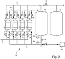
- Fig. 2 shows a PSA apparatus 20, which is different from the apparatus 10 in fig. 1 , in that the off-gas manifold 11 is connected to the off-gas storage vessel 23 via a branch conduit in which a first pressure sensor 25, a valve 26 and a second pressure sensor 27 are provided.
- the off gas-vessel valve 23 When the pressure in the off gas vessel 23 as measured by the second pressure sensor 27 is higher than the pressure in the off-gas manifold 11, as measured by the first pressure sensor 25, the off gas-vessel valve 23 is opened and the off-gas vessel 23 is filled. When the pressure in the off-gas manifold 11 is reduced below a certain value, the valve is opened and the off gas valves 15 of the respective the PSA vessels 1, 2, 3, 4 are closed.
- both apparatus 10 20 during the purge of a vessel 1, 2, 3, 4 the pressure is also reduced because of the quicker pressure reduction when the burner 28 is consuming only from the respective purge giving vessel. If the supply of the purge is controlled, the whole purge can proceed at a pressure close to the minimum inlet pressure of the burner controls.
Landscapes
- Chemical & Material Sciences (AREA)
- Engineering & Computer Science (AREA)
- Analytical Chemistry (AREA)
- General Chemical & Material Sciences (AREA)
- Oil, Petroleum & Natural Gas (AREA)
- Chemical Kinetics & Catalysis (AREA)
- Separation Of Gases By Adsorption (AREA)
- Hydrogen, Water And Hydrids (AREA)
Claims (15)
- Verfahren zum Trennen eines Gasgemisches gemäß einem Druckwechsel-Adsorption Verfahren (PSA process), umfassend den Schritt des Trennens des Gasgemisches durch das Adsorbieren von zumindest einem Gasbestandteil in eine Adsorptionsmasse (5), die in jedem Gefäß einer Mehrzahl von Gefäßen (1, 2, 3, 4) bereitgestellt ist, wobei jedes Gefäß (1, 2, 3, 4) zumindest einen Einlass (6) und einen Auslass (7) hat, welches Verfahren weiter den Schritt des Lagerns von Abgas aus dem genannten Verfahren in ein Abgas-Gefäß (23) umfasst, wobei in jedem der genannten Gefäße (1, 2, 3, 4) die nachfolgenden Schritte zu unterscheiden sind:(i) das während einer vorher bestimmten Zeit Einlassen des Gasgemisches in ein erstes Gefäß (1) über einen Einlass (6) dieses Gefäßes (1), und das Auslassen eines abgetrennten Produktgases über einen Auslass (7) dieses Gefäßes (1), gefolgt durch das Einlassen des Gasgemisches in ein zweites Gefäß (2), unter Fortsetzung des Auslassens des Produktgases aus dem ersten Gefäß (1), gefolgt durch(ii) das aus dem ersten Gefäß (1) über seinen Auslass (7) Auslassen von Reinigungsgas,(iii) das Auslassen von Abgas aus dem ersten Gefäß (1) über seinen Einlass (6) und das Einlassen von zumindest einen Teil dieses Abgases in das Abgas-Gefäß (23),(iv) das Einlassen von Reinigungsgas in das erste Gefäß (1) über seinen Auslass (7), und das Auslassen von Abgas aus diesem Gefäß (1) über seinen Einlass (6), und(v) das Einlassen eines abgetrennten Produktgases in das erste Gefäß (1) bis der Druck in dem ersten Gefäß (1) einen vorher bestimmten Wert erreicht hat, wonach das Einlassen des Gasgemisches in das erste Gefäß (1) beginnt, und die Schritte beginnend mit Schritt (i) wiederholt werden, wobei während wenigstens einem der Schritte (iii) und (iv) zumindest ein Teil des Abgases aus dem ersten Gefäß (1) direkt zu einer Abgas verbrauchenden Einrichtung (28) ausgelassen wird, gekennzeichnet durch(a) das direkte Verbinden,
in einen ersten Zustand, in dem pi > pb und pi > po+Δ, von jedem der Gefäße (1, 2, 3, 4) mit sowohl der Abgas verbrauchenden Einrichtung (28) als auch dem Abgas-Lagergefäß (23),(b) das direkte Verbinden,
in einen zweiten Zustand, in dem pi > pb und pi ≤ po+Δ, von jedem der Gefäße (1, 2, 3, 4) mit nur der Abgasverbrauchende Einrichtung (28), und(c) das Verbinden,
in einen dritten Zustand, in dem pi < pb und po > pb,
des Abgas-Lagergefäßes (23) mit der Abgas verbrauchenden Einrichtung (28), wobei- pi den Wert des Drucks an dem Einlass (6) repräsentiert,- po den Wert des Drucks in dem Lagergefäß (23) repräsentiert,- pb einen Druck mit einem vorher bestimmten Wert repräsentiert, und- Δ eine vorher bestimmte Druckdifferenz repräsentiert. - Verfahren gemäß Anspruch 1,
wobei das Gasgemisch Wasserstoffgas enthält und das Produktgas Wasserstoff ist. - Verfahren gemäß einem der Ansprüche 1-2, wobei die Abgas verbrauchende Einrichtung einen Brenner (28) umfasst.
- Einrichtung (10, 20) zum Trennen eines Gasgemisches gemäß einem Druckwechsel-Adsorption Verfahren (PSA process), umfassend eine Mehrzahl von Gefäßen (1, 2, 3, 4), wobei jedes Gefäß (1, 2, 3, 4) zumindest einen Einlass (6) und einen Auslass (7) hat, in jedem dieser Gefäße (1, 2, 3, 4) eine Adsorptionsmasse (5) zum Adsorbieren von zumindest einem Gasbestandteil bereitgestellt ist, und der Einlass (6) von jedem dieser Gefäße (1, 2, 3, 4) mit einem Lagergefäß (23) für ein Abgas verbunden ist, wobei der Einlass (6) von jedem der Gefäße (1, 2, 3, 4) und das Lagergefäß (23) weiter mit einer Abgas verbrauchenden Einrichtung (28) verbunden sind, und wobei Regel- und Verbindungsmittel (21, 22, 24; 21, 25, 26, 27) bereitgestellt sind für(a) das in einen ersten Zustand, in dem pi > pb und pi > po+Δ, direkte Verbinden von jedem der Gefäße (1, 2, 3, 4) mit sowohl der Abgas verbrauchenden Einrichtung (28) als auch dem Abgas-Lagergefäß (23),(b) das in einen zweiten Zustand, in dem pi > pb und pi ≤ po+Δ, direkte Verbinden, von jedem der Gefäße (1, 2, 3, 4) mit nur der Abgas verbrauchenden Einrichtung (28), und(c) das in einen dritten Zustand, in dem pi < pb und po > pb, Verbinden des Abgas-Lagergefäß (23) mit der Abgas verbrauchenden Einrichtung (28), wobei- pi den Wert des Drucks an dem Einlass (6) repräsentiert,- po den Wert des Drucks in dem Lagergefäß (23) repräsentiert,- pb ein Druck mit einem vorher bestimmten Wert repräsentiert, und- Δ eine vorher bestimmte Druckdifferenz repräsentiert.
- Einrichtung (10) gemäß Anspruch 4, dadurch gekennzeichnet, dass jeder Einlass (6) durch eine gemeinsame Leitung (11) mit der Abgas verbrauchenden Einrichtung (28) verbunden ist, die eine erste Regeleinrichtung (21) hat, welche mit einer Umgehungsleitung ausgestattet ist, die ein Rückschlagventil (22), eine mit dem Abgasgefäß (23) verbundene Abzweigung und eine zweite Regeleinrichtung (24) hat.
- Einrichtung (10) gemäß Anspruch 5, dadurch gekennzeichnet, dass die erste Regeleinrichtung eine Druckreduziereinrichtung (21) und die zweite Regeleinrichtung eine Druckreduziereinrichtung (24) ist.
- Einrichtung (10) gemäß Anspruch 5, dadurch gekennzeichnet, dass die erste Regeleinrichtung ein Regelventil und die zweite Regeleinrichtung ein Regelventil ist.
- Einrichtung (10) gemäß Anspruch 5, dadurch gekennzeichnet, dass die erste Regeleinrichtung ein Regelventil und die zweite Regeleinrichtung ein Druckregler ist.
- Einrichtung (10) gemäß Anspruch 8, dadurch gekennzeichnet, dass der Druckregler eine Druckreduziereinrichtung und ein Regelventil umfasst.
- Einrichtung gemäß Anspruch 4, dadurch gekennzeichnet, dass jeder Einlass (6) durch eine gemeinsame Leitung (11) mit der Abgas verbrauchenden Einrichtung (28) verbunden ist, die mit einer ersten Regeleinrichtung und mit einer sich zwischen den Einlässen (6) und dieser ersten Regeleinrichtung erstreckenden Umgehungsleitung mit einem Rückschlagventil, einer mit dem Abgas-Gefäß verbundenen Abzweigung und einer zweiten Regeleinrichtung ausgestattet ist.
- Einrichtung gemäß Anspruch 4, dadurch gekennzeichnet, dass jeder Einlass (6) durch eine gemeinsame Leitung (11) mit der Abgas verbrauchenden Einrichtung (28) verbunden ist, welche gemeinsame Leitung (11) über eine Abzweigleitung mit dem Abgas-Lagergefäß (23) verbunden ist, in der ein erster Drucksensor (25), ein Ventil (26) und ein zweiter Drucksensor (27) bereitgestellt sind.
- Einrichtung gemäß Anspruch 4, dadurch gekennzeichnet, dass jeder Einlass (6) durch eine gemeinsame Leitung (11) mit der Abgas verbrauchenden Einrichtung (28) verbunden ist, die eine erste Regeleinrichtung (21) hat, welche mit einer durch das Abgas-Gefäß leitenden Umgehungsleitung ausgestattet ist, die ein Rückschlagventil (22) und eine zweite Regeleinrichtung (24) hat.
- Einrichtung (10, 20) gemäß einem der Ansprüche 4-12, dadurch gekennzeichnet, dass die Mehrzahl der Gefäße zumindest zwei Gefäße (1, 2, 3) umfasst.
- Einrichtung (10, 20) gemäß einem der Ansprüche 4-13, dadurch gekennzeichnet, dass die Mehrzahl der Gefäße vier Gefäße (1, 2, 3, 4) umfasst.
- Einrichtung (10, 20) gemäß einem der Ansprüche 4-14, dadurch gekennzeichnet, dass die Abgas verbrauchende Einrichtung einen Brenner (28) umfasst.
Priority Applications (1)
| Application Number | Priority Date | Filing Date | Title |
|---|---|---|---|
| PL13818524T PL2938423T3 (pl) | 2012-12-28 | 2013-12-24 | Sposób i urządzenie do rozdzielania mieszaniny gazowej przez adsorpcję zmiennociśnieniową |
Applications Claiming Priority (2)
| Application Number | Priority Date | Filing Date | Title |
|---|---|---|---|
| NL2010072A NL2010072C2 (en) | 2012-12-28 | 2012-12-28 | Method and device for separating a gas mixture by means of pressure swing adsorption. |
| PCT/NL2013/050958 WO2014104891A1 (en) | 2012-12-28 | 2013-12-24 | Method and device for separating a gas mixture by means of pressure swing adsorption |
Publications (2)
| Publication Number | Publication Date |
|---|---|
| EP2938423A1 EP2938423A1 (de) | 2015-11-04 |
| EP2938423B1 true EP2938423B1 (de) | 2017-02-01 |
Family
ID=47682042
Family Applications (1)
| Application Number | Title | Priority Date | Filing Date |
|---|---|---|---|
| EP13818524.4A Active EP2938423B1 (de) | 2012-12-28 | 2013-12-24 | Verfahren und vorrichtung zur trennung einer gasmischung mittels druckwechseladsorption |
Country Status (7)
| Country | Link |
|---|---|
| US (1) | US9656202B2 (de) |
| EP (1) | EP2938423B1 (de) |
| DK (1) | DK2938423T3 (de) |
| ES (1) | ES2622901T3 (de) |
| NL (1) | NL2010072C2 (de) |
| PL (1) | PL2938423T3 (de) |
| WO (1) | WO2014104891A1 (de) |
Families Citing this family (8)
| Publication number | Priority date | Publication date | Assignee | Title |
|---|---|---|---|---|
| NL2015435B1 (nl) * | 2015-09-14 | 2017-04-03 | Green Vision Holding Bv | Werkwijze en inrichting voor het scheiden van een gasmengsel volgens een pressure swing adsorption process (PSA process). |
| CN107008104B (zh) * | 2017-05-23 | 2020-02-11 | 成都赛普瑞兴科技有限公司 | 一种变压吸附装置及有效气回收方法 |
| CN107158884B (zh) * | 2017-05-23 | 2019-10-22 | 成都赛普瑞兴科技有限公司 | 一种变压吸附装置及有效气回收方法 |
| CN213259295U (zh) | 2017-10-20 | 2021-05-25 | 米沃奇电动工具公司 | 用于通过凿子在工件上执行开凿操作的冲击工具 |
| EP4349534A3 (de) | 2018-01-26 | 2024-07-17 | Milwaukee Electric Tool Corporation | Schlagwerkzeug |
| CN215617869U (zh) | 2018-04-04 | 2022-01-25 | 米沃奇电动工具公司 | 一种适于向工具头施加轴向冲击的旋转锤 |
| CN109173582A (zh) * | 2018-09-28 | 2019-01-11 | 安徽节源环保科技有限公司 | 一种污泥恶臭气体的处理系统 |
| EP3782712B1 (de) * | 2019-08-21 | 2023-08-02 | Air Products And Chemicals, Inc. | Verringerung von schwankungen im endgasstrom und treibstoffeigenschaften einer adsorptionseinheit |
Family Cites Families (11)
| Publication number | Priority date | Publication date | Assignee | Title |
|---|---|---|---|---|
| US4539020A (en) * | 1983-07-10 | 1985-09-03 | Kawasaki Steel Corporation | Methods for obtaining high-purity carbon monoxide |
| GB8826584D0 (en) * | 1988-11-14 | 1988-12-21 | Boc Group Plc | Pressure swing adsorption process |
| US5154736A (en) * | 1991-03-29 | 1992-10-13 | Shell Oil Company | Process for the separation of a gas mixture |
| US6007606A (en) * | 1997-12-09 | 1999-12-28 | Praxair Technology, Inc. | PSA process and system |
| FR2786110B1 (fr) * | 1998-11-23 | 2001-01-19 | Air Liquide | Procede de separation par adsorption modulee en pression d'un melange de gaz et installation pour sa mise en oeuvre |
| FR2788993B1 (fr) * | 1999-01-29 | 2001-02-23 | Air Liquide | Procede d'epuration d'un gaz par adsorption |
| FR2832398B1 (fr) * | 2001-11-22 | 2004-10-01 | Air Liquide | Installation de production d'hydrogene et procedes pour la mise en oeuvre de cette installation |
| JP4771668B2 (ja) * | 2004-03-31 | 2011-09-14 | 大阪瓦斯株式会社 | 水素製造方法とその装置 |
| AU2006204976B2 (en) | 2005-01-12 | 2010-08-19 | Lummus Technology Inc. | Methods and apparatus for improved control of PSA flow variations |
| JP5537208B2 (ja) * | 2010-03-24 | 2014-07-02 | 大阪瓦斯株式会社 | 可燃性ガス濃縮方法 |
| JP6198646B2 (ja) * | 2013-07-19 | 2017-09-20 | 大阪瓦斯株式会社 | 圧力変動吸着式水素製造方法 |
-
2012
- 2012-12-28 NL NL2010072A patent/NL2010072C2/en not_active IP Right Cessation
-
2013
- 2013-12-24 DK DK13818524.4T patent/DK2938423T3/en active
- 2013-12-24 EP EP13818524.4A patent/EP2938423B1/de active Active
- 2013-12-24 PL PL13818524T patent/PL2938423T3/pl unknown
- 2013-12-24 ES ES13818524.4T patent/ES2622901T3/es active Active
- 2013-12-24 US US14/758,320 patent/US9656202B2/en active Active
- 2013-12-24 WO PCT/NL2013/050958 patent/WO2014104891A1/en not_active Ceased
Non-Patent Citations (1)
| Title |
|---|
| None * |
Also Published As
| Publication number | Publication date |
|---|---|
| US9656202B2 (en) | 2017-05-23 |
| ES2622901T3 (es) | 2017-07-07 |
| DK2938423T3 (en) | 2017-05-01 |
| PL2938423T3 (pl) | 2017-07-31 |
| EP2938423A1 (de) | 2015-11-04 |
| WO2014104891A1 (en) | 2014-07-03 |
| US20150328579A1 (en) | 2015-11-19 |
| NL2010072C2 (en) | 2014-07-03 |
Similar Documents
| Publication | Publication Date | Title |
|---|---|---|
| EP2938423B1 (de) | Verfahren und vorrichtung zur trennung einer gasmischung mittels druckwechseladsorption | |
| JP5134704B2 (ja) | オフガス供給方法 | |
| KR101501815B1 (ko) | 고로가스의 분리방법 및 장치 | |
| CA2331034C (en) | Pressure swing adsorption process with multiple beds on purge and/or with ten beds and four pressure equalization steps | |
| KR101681543B1 (ko) | 질소 농축 가스 제조 방법, 가스 분리 방법 및 질소 농축 가스 제조 장치 | |
| EP2374522A1 (de) | Verfahren zur Wiedergewinnung von Kohlendioxid mittlerer Reinheit | |
| NO144446B (no) | Adiabatisk trykkretsprosess for separasjon av gassblandinger | |
| JPS5922625A (ja) | 一酸化炭素ガス及び窒素ガスを含む混合ガスより窒素ガスを吸着法により除去する方法 | |
| US5620501A (en) | Recovery of trace gases from gas streams | |
| CA2824358A1 (en) | Six bed pressure swing adsorption process operating in normal and turndown modes | |
| CN101516472A (zh) | 二氧化碳回收方法 | |
| US20250128201A1 (en) | Method and system for upgrading biogas using psa | |
| JPH04338206A (ja) | ガスの分離方法 | |
| EP3349878B1 (de) | Druckwechseladsorptionsverfahren und -vorrichtung zur reinigung eines wasserstoffhaltigen gasstroms | |
| JP2009226258A (ja) | 高炉ガスの分離方法、および高炉ガスの分離装置 | |
| JP2003192315A (ja) | ヘリウム精製装置 | |
| AU2016201267B2 (en) | A plant and process for simutaneous recovering multiple gas products from petrochemical offgas | |
| JP2002355519A (ja) | 水素精製用4塔式圧力スイング吸着装置の安定運転方法 | |
| CA2452536C (en) | Pressure swing adsorption process with multiple beds on purge and/or with ten beds and four pressure equalization steps | |
| AU2013201122A1 (en) | A plant and process for simutaneous recovering multiple gas products from industry offgas | |
| JPH01230415A (ja) | Co及びco↓2ガスの分離方法 |
Legal Events
| Date | Code | Title | Description |
|---|---|---|---|
| PUAI | Public reference made under article 153(3) epc to a published international application that has entered the european phase |
Free format text: ORIGINAL CODE: 0009012 |
|
| 17P | Request for examination filed |
Effective date: 20150710 |
|
| AK | Designated contracting states |
Kind code of ref document: A1 Designated state(s): AL AT BE BG CH CY CZ DE DK EE ES FI FR GB GR HR HU IE IS IT LI LT LU LV MC MK MT NL NO PL PT RO RS SE SI SK SM TR |
|
| AX | Request for extension of the european patent |
Extension state: BA ME |
|
| DAX | Request for extension of the european patent (deleted) | ||
| GRAP | Despatch of communication of intention to grant a patent |
Free format text: ORIGINAL CODE: EPIDOSNIGR1 |
|
| INTG | Intention to grant announced |
Effective date: 20161018 |
|
| GRAS | Grant fee paid |
Free format text: ORIGINAL CODE: EPIDOSNIGR3 |
|
| GRAA | (expected) grant |
Free format text: ORIGINAL CODE: 0009210 |
|
| AK | Designated contracting states |
Kind code of ref document: B1 Designated state(s): AL AT BE BG CH CY CZ DE DK EE ES FI FR GB GR HR HU IE IS IT LI LT LU LV MC MK MT NL NO PL PT RO RS SE SI SK SM TR |
|
| REG | Reference to a national code |
Ref country code: GB Ref legal event code: FG4D |
|
| REG | Reference to a national code |
Ref country code: CH Ref legal event code: EP Ref country code: AT Ref legal event code: REF Ref document number: 865065 Country of ref document: AT Kind code of ref document: T Effective date: 20170215 |
|
| REG | Reference to a national code |
Ref country code: IE Ref legal event code: FG4D |
|
| REG | Reference to a national code |
Ref country code: DE Ref legal event code: R096 Ref document number: 602013017185 Country of ref document: DE |
|
| REG | Reference to a national code |
Ref country code: NL Ref legal event code: FP |
|
| REG | Reference to a national code |
Ref country code: DK Ref legal event code: T3 Effective date: 20170427 |
|
| REG | Reference to a national code |
Ref country code: LT Ref legal event code: MG4D |
|
| REG | Reference to a national code |
Ref country code: AT Ref legal event code: MK05 Ref document number: 865065 Country of ref document: AT Kind code of ref document: T Effective date: 20170201 |
|
| REG | Reference to a national code |
Ref country code: ES Ref legal event code: FG2A Ref document number: 2622901 Country of ref document: ES Kind code of ref document: T3 Effective date: 20170707 |
|
| PG25 | Lapsed in a contracting state [announced via postgrant information from national office to epo] |
Ref country code: GR Free format text: LAPSE BECAUSE OF FAILURE TO SUBMIT A TRANSLATION OF THE DESCRIPTION OR TO PAY THE FEE WITHIN THE PRESCRIBED TIME-LIMIT Effective date: 20170502 Ref country code: HR Free format text: LAPSE BECAUSE OF FAILURE TO SUBMIT A TRANSLATION OF THE DESCRIPTION OR TO PAY THE FEE WITHIN THE PRESCRIBED TIME-LIMIT Effective date: 20170201 Ref country code: FI Free format text: LAPSE BECAUSE OF FAILURE TO SUBMIT A TRANSLATION OF THE DESCRIPTION OR TO PAY THE FEE WITHIN THE PRESCRIBED TIME-LIMIT Effective date: 20170201 Ref country code: IS Free format text: LAPSE BECAUSE OF FAILURE TO SUBMIT A TRANSLATION OF THE DESCRIPTION OR TO PAY THE FEE WITHIN THE PRESCRIBED TIME-LIMIT Effective date: 20170601 Ref country code: LT Free format text: LAPSE BECAUSE OF FAILURE TO SUBMIT A TRANSLATION OF THE DESCRIPTION OR TO PAY THE FEE WITHIN THE PRESCRIBED TIME-LIMIT Effective date: 20170201 Ref country code: NO Free format text: LAPSE BECAUSE OF FAILURE TO SUBMIT A TRANSLATION OF THE DESCRIPTION OR TO PAY THE FEE WITHIN THE PRESCRIBED TIME-LIMIT Effective date: 20170501 |
|
| PG25 | Lapsed in a contracting state [announced via postgrant information from national office to epo] |
Ref country code: PT Free format text: LAPSE BECAUSE OF FAILURE TO SUBMIT A TRANSLATION OF THE DESCRIPTION OR TO PAY THE FEE WITHIN THE PRESCRIBED TIME-LIMIT Effective date: 20170601 Ref country code: LV Free format text: LAPSE BECAUSE OF FAILURE TO SUBMIT A TRANSLATION OF THE DESCRIPTION OR TO PAY THE FEE WITHIN THE PRESCRIBED TIME-LIMIT Effective date: 20170201 Ref country code: SE Free format text: LAPSE BECAUSE OF FAILURE TO SUBMIT A TRANSLATION OF THE DESCRIPTION OR TO PAY THE FEE WITHIN THE PRESCRIBED TIME-LIMIT Effective date: 20170201 Ref country code: AT Free format text: LAPSE BECAUSE OF FAILURE TO SUBMIT A TRANSLATION OF THE DESCRIPTION OR TO PAY THE FEE WITHIN THE PRESCRIBED TIME-LIMIT Effective date: 20170201 Ref country code: BG Free format text: LAPSE BECAUSE OF FAILURE TO SUBMIT A TRANSLATION OF THE DESCRIPTION OR TO PAY THE FEE WITHIN THE PRESCRIBED TIME-LIMIT Effective date: 20170501 Ref country code: RS Free format text: LAPSE BECAUSE OF FAILURE TO SUBMIT A TRANSLATION OF THE DESCRIPTION OR TO PAY THE FEE WITHIN THE PRESCRIBED TIME-LIMIT Effective date: 20170201 |
|
| PG25 | Lapsed in a contracting state [announced via postgrant information from national office to epo] |
Ref country code: RO Free format text: LAPSE BECAUSE OF FAILURE TO SUBMIT A TRANSLATION OF THE DESCRIPTION OR TO PAY THE FEE WITHIN THE PRESCRIBED TIME-LIMIT Effective date: 20170201 Ref country code: CZ Free format text: LAPSE BECAUSE OF FAILURE TO SUBMIT A TRANSLATION OF THE DESCRIPTION OR TO PAY THE FEE WITHIN THE PRESCRIBED TIME-LIMIT Effective date: 20170201 Ref country code: EE Free format text: LAPSE BECAUSE OF FAILURE TO SUBMIT A TRANSLATION OF THE DESCRIPTION OR TO PAY THE FEE WITHIN THE PRESCRIBED TIME-LIMIT Effective date: 20170201 Ref country code: SK Free format text: LAPSE BECAUSE OF FAILURE TO SUBMIT A TRANSLATION OF THE DESCRIPTION OR TO PAY THE FEE WITHIN THE PRESCRIBED TIME-LIMIT Effective date: 20170201 |
|
| REG | Reference to a national code |
Ref country code: DE Ref legal event code: R097 Ref document number: 602013017185 Country of ref document: DE |
|
| PG25 | Lapsed in a contracting state [announced via postgrant information from national office to epo] |
Ref country code: SM Free format text: LAPSE BECAUSE OF FAILURE TO SUBMIT A TRANSLATION OF THE DESCRIPTION OR TO PAY THE FEE WITHIN THE PRESCRIBED TIME-LIMIT Effective date: 20170201 |
|
| REG | Reference to a national code |
Ref country code: FR Ref legal event code: PLFP Year of fee payment: 5 |
|
| PLBE | No opposition filed within time limit |
Free format text: ORIGINAL CODE: 0009261 |
|
| STAA | Information on the status of an ep patent application or granted ep patent |
Free format text: STATUS: NO OPPOSITION FILED WITHIN TIME LIMIT |
|
| 26N | No opposition filed |
Effective date: 20171103 |
|
| PG25 | Lapsed in a contracting state [announced via postgrant information from national office to epo] |
Ref country code: SI Free format text: LAPSE BECAUSE OF FAILURE TO SUBMIT A TRANSLATION OF THE DESCRIPTION OR TO PAY THE FEE WITHIN THE PRESCRIBED TIME-LIMIT Effective date: 20170201 |
|
| REG | Reference to a national code |
Ref country code: CH Ref legal event code: PL |
|
| REG | Reference to a national code |
Ref country code: IE Ref legal event code: MM4A |
|
| PG25 | Lapsed in a contracting state [announced via postgrant information from national office to epo] |
Ref country code: MT Free format text: LAPSE BECAUSE OF NON-PAYMENT OF DUE FEES Effective date: 20171224 Ref country code: LU Free format text: LAPSE BECAUSE OF NON-PAYMENT OF DUE FEES Effective date: 20171224 |
|
| PG25 | Lapsed in a contracting state [announced via postgrant information from national office to epo] |
Ref country code: IE Free format text: LAPSE BECAUSE OF NON-PAYMENT OF DUE FEES Effective date: 20171224 |
|
| REG | Reference to a national code |
Ref country code: FR Ref legal event code: PLFP Year of fee payment: 6 |
|
| PG25 | Lapsed in a contracting state [announced via postgrant information from national office to epo] |
Ref country code: CH Free format text: LAPSE BECAUSE OF NON-PAYMENT OF DUE FEES Effective date: 20171231 Ref country code: LI Free format text: LAPSE BECAUSE OF NON-PAYMENT OF DUE FEES Effective date: 20171231 |
|
| PG25 | Lapsed in a contracting state [announced via postgrant information from national office to epo] |
Ref country code: MC Free format text: LAPSE BECAUSE OF FAILURE TO SUBMIT A TRANSLATION OF THE DESCRIPTION OR TO PAY THE FEE WITHIN THE PRESCRIBED TIME-LIMIT Effective date: 20170201 Ref country code: HU Free format text: LAPSE BECAUSE OF FAILURE TO SUBMIT A TRANSLATION OF THE DESCRIPTION OR TO PAY THE FEE WITHIN THE PRESCRIBED TIME-LIMIT; INVALID AB INITIO Effective date: 20131224 |
|
| PG25 | Lapsed in a contracting state [announced via postgrant information from national office to epo] |
Ref country code: CY Free format text: LAPSE BECAUSE OF FAILURE TO SUBMIT A TRANSLATION OF THE DESCRIPTION OR TO PAY THE FEE WITHIN THE PRESCRIBED TIME-LIMIT Effective date: 20170201 |
|
| PG25 | Lapsed in a contracting state [announced via postgrant information from national office to epo] |
Ref country code: MK Free format text: LAPSE BECAUSE OF FAILURE TO SUBMIT A TRANSLATION OF THE DESCRIPTION OR TO PAY THE FEE WITHIN THE PRESCRIBED TIME-LIMIT Effective date: 20170201 |
|
| PG25 | Lapsed in a contracting state [announced via postgrant information from national office to epo] |
Ref country code: AL Free format text: LAPSE BECAUSE OF FAILURE TO SUBMIT A TRANSLATION OF THE DESCRIPTION OR TO PAY THE FEE WITHIN THE PRESCRIBED TIME-LIMIT Effective date: 20170201 |
|
| PGFP | Annual fee paid to national office [announced via postgrant information from national office to epo] |
Ref country code: DE Payment date: 20241029 Year of fee payment: 12 |
|
| PGFP | Annual fee paid to national office [announced via postgrant information from national office to epo] |
Ref country code: DK Payment date: 20241023 Year of fee payment: 12 |
|
| PGFP | Annual fee paid to national office [announced via postgrant information from national office to epo] |
Ref country code: BE Payment date: 20241101 Year of fee payment: 12 Ref country code: PL Payment date: 20241021 Year of fee payment: 12 Ref country code: NL Payment date: 20241202 Year of fee payment: 12 |
|
| PGFP | Annual fee paid to national office [announced via postgrant information from national office to epo] |
Ref country code: GB Payment date: 20241023 Year of fee payment: 12 |
|
| PGFP | Annual fee paid to national office [announced via postgrant information from national office to epo] |
Ref country code: FR Payment date: 20241128 Year of fee payment: 12 |
|
| PGFP | Annual fee paid to national office [announced via postgrant information from national office to epo] |
Ref country code: IT Payment date: 20241126 Year of fee payment: 12 |
|
| PGFP | Annual fee paid to national office [announced via postgrant information from national office to epo] |
Ref country code: TR Payment date: 20241101 Year of fee payment: 12 |
|
| PGFP | Annual fee paid to national office [announced via postgrant information from national office to epo] |
Ref country code: ES Payment date: 20250102 Year of fee payment: 12 |