EP2938158A1 - Système destiné à la mise à disposition d'accès à large bande pour un réseau de trafic à grande distance - Google Patents
Système destiné à la mise à disposition d'accès à large bande pour un réseau de trafic à grande distance Download PDFInfo
- Publication number
- EP2938158A1 EP2938158A1 EP14165910.2A EP14165910A EP2938158A1 EP 2938158 A1 EP2938158 A1 EP 2938158A1 EP 14165910 A EP14165910 A EP 14165910A EP 2938158 A1 EP2938158 A1 EP 2938158A1
- Authority
- EP
- European Patent Office
- Prior art keywords
- subscriber
- radio
- access technology
- antenna
- network access
- Prior art date
- Legal status (The legal status is an assumption and is not a legal conclusion. Google has not performed a legal analysis and makes no representation as to the accuracy of the status listed.)
- Granted
Links
Images


Classifications
-
- H—ELECTRICITY
- H04—ELECTRIC COMMUNICATION TECHNIQUE
- H04W—WIRELESS COMMUNICATION NETWORKS
- H04W84/00—Network topologies
- H04W84/02—Hierarchically pre-organised networks, e.g. paging networks, cellular networks, WLAN [Wireless Local Area Network] or WLL [Wireless Local Loop]
- H04W84/10—Small scale networks; Flat hierarchical networks
-
- H—ELECTRICITY
- H04—ELECTRIC COMMUNICATION TECHNIQUE
- H04W—WIRELESS COMMUNICATION NETWORKS
- H04W84/00—Network topologies
- H04W84/005—Moving wireless networks
-
- H—ELECTRICITY
- H04—ELECTRIC COMMUNICATION TECHNIQUE
- H04W—WIRELESS COMMUNICATION NETWORKS
- H04W88/00—Devices specially adapted for wireless communication networks, e.g. terminals, base stations or access point devices
- H04W88/02—Terminal devices
- H04W88/04—Terminal devices adapted for relaying to or from another terminal or user
-
- H—ELECTRICITY
- H04—ELECTRIC COMMUNICATION TECHNIQUE
- H04W—WIRELESS COMMUNICATION NETWORKS
- H04W88/00—Devices specially adapted for wireless communication networks, e.g. terminals, base stations or access point devices
- H04W88/02—Terminal devices
- H04W88/06—Terminal devices adapted for operation in multiple networks or having at least two operational modes, e.g. multi-mode terminals
Definitions
- the invention relates to an arrangement for providing broadband access for a wide area network, in particular the Internet. It refers to the provision of access to a wide area network, the core network is of course also broadband or formed in the form of a high-speed network.
- the following illustrations generally relate to the provision of broadband Internet access, but the invention is not limited to the Internet according to its title and the claimed subject-matter, but is generally concerned with the provision of broadband accesses to a wide area network. For the sake of simplicity only, generally, the Internet will be referred to below.
- broadband access network to the Internet is a recognized economic policy task.
- broadband ie high transmission rates providing networks or networks are formed wired, this is currently realized in particular by the use of fiber optic cables.
- fiber optic cables The same applies to corresponding broadband access networks to such networks.
- accesses or networks are to be considered, which allow according to the definition given by the ITU (International Telecommunication Union) definition, a data transmission rate of 2048 kbit / s or more.
- Such transmission rates are, for example, over long distances, that is several kilometers away by means of Kupferdoppeladern unreachable, since with increasing distance, the attenuation of the transmitted useful signal increases significantly.
- FTTCab Fiber To The Cabinet
- a fiber in the main cable section is routed to a multi-function roadside enclosure - typically at the site of the cable divider (KVz) - and a broadband signal only in the short section between this multi-function cabinet called the Cabinet individual subscriber lines transmitted over a relatively short copper pair.
- the FTTB approach Fiber To The Building
- a fiber is routed right into every house, and then only distributed within the house to the connections via copper double wires, goes a little further.
- the achievable access bit rates ie the achievable transmission rates in the access network, thereby increase, the more fiber optic cables are brought in the direction of a respective subscriber line.
- the associated costs are very high. This is particularly due to the necessary earthworks to introduce fiber optic cable up to a multi-function housing on the roadside (Cabinet) or possibly even up to the individual buildings. But the installation within buildings is associated with a not inconsiderable cost, in particular the latter applies not only to the use of fiber optic cables, but also with respect to the installation of corresponding copper wires.
- the inclusion of radio technology offers opportunities to reduce the cost of broadband subscribers.
- solutions have become known, which can be called in a sense as hybrid solutions.
- the broadband signals in the access network sections via different channels, namely in a directly connected to the wide area network or the core network first section wired, preferably via fiber optic cable, and transmitted in another section, the last transmission section to the subscriber via radio.
- a fiber optic cable is routed to a kind of headend.
- This head-end station defined as access point (access point) is a preferably centrally located conversion and radio transmission device.
- This is preferably in the form of a high antenna mast, on which, in addition to the antenna, the already mentioned converter as well as transmitting and receiving units for radio transmission are arranged.
- the converter By the converter are from the direction of the wide area network wired incoming signals with data converted into radio signals and emitted by means of the aforementioned radio transmitter and radio receiver units and the antenna.
- an antenna On the subscriber side, an antenna is arranged to receive the radio signals transmitted by the access point, with a corresponding antenna for each individual subscriber or a smaller one Group of participants is provided.
- the subscriber-side antenna further includes at least one transmitting and receiving unit for radio transmission and a terminal unit (wireless terminal - WT), which converts the received radio signals again into cables to be relayed signals.
- the last-mentioned signals transmitted by line are finally forwarded via a corresponding subscriber line, such as an Ethernet cable, to the respective subscriber intended for their reception, that is to a terminal used by the latter.
- a special interface device designated as a WT adapter is to be arranged as an additional device. From the respective participants outgoing signals take the opposite route, whereby they first transmitted via the subscriber line to the subscriber's antenna with associated converter and radio transmitter and radio receiver unit, transmitted from here by radio to the access point and finally after re-implementation via the fiber optic cable at the access point be forwarded to the wide area network.
- each participant in addition to a converter and at least one radio transmitter and radio receiving unit is to be provided in each case a to be arranged on the building facade antenna.
- a multi-family house with a plurality of subscribers supplied with this method by means of an Internet connection it is very disadvantageous in terms of optics if a plurality of antennas are to be arranged on the front of the house for this purpose.
- the solution known as WIPAS still has the disadvantage that in the premises of a participant special equipment in the form of the aforementioned WT adapter is provided, which in turn requires space and possibly, as well as the antenna, on the outer facade of the building as visually distracting.
- Object of the present invention is to avoid the disadvantages listed above.
- an arrangement is to be specified, which makes it possible to provide inexpensive and efficient broadband access to a wide area network, without being perceived as disturbing in particular from an optical point of view.
- the proposed arrangement for solving the problem is based on a hybrid approach.
- the arrangement consists of at least one fixed, directly to the wide area network connected network access point and subscriber-side, with a fixed network access point via radio connectable access technology.
- the at least one fixed network access point is wired to the wide area network, preferably by means of fiber optic cable, broadband connected.
- the subscriber-side access technology to be provided per subscriber line which can be connected to a fixed network access point by means of at least one computer-based terminal, comprises at least one antenna with transmitting and receiving units for radio-based communication with a fixed network access point, a router device in the form of a Broadband router and at least one interface to the wireless and / or circuit-based connection of at least the aforementioned computer-based terminal with the router device.
- the arrangement presented for achieving the object is characterized in particular by the fact that the subscriber-side access technology characterized in greater detail above is incorporated in the envelope of a stationary object (for example a building) or a mobile object (for example of a vehicle).
- the at least one antenna of the relevant subscriber-side access technology which is provided for radio-based communication with a stationary network access point, is arranged directly on or within a component of the envelope of the object.
- the transmitting and receiving units operated on this antenna for radio-based communication with a fixed network access point and the router device according to the invention are integrated into a component of the shell of the object.
- the aforementioned stationary objects incorporating subscriber-side access technology into their shell may involve a wide variety of structures or buildings, in particular residential buildings in the form of single-family or multi-family houses, pure office buildings or factory buildings, but of course also public buildings, for example railway stations. Airport buildings, hospitals, schools or town halls.
- the feature of the proposed arrangement according to which the subscriber-side access technology antenna for radio-based communication with a fixed network access point is located directly on a component of the shell of an object means that the antenna is not (at least not visually immediately perceptible to, or by a viewer distracting) from the shell of the object, such as the façade or associated elements of a building.
- the antenna is in this case preferably flat against an outer surface of a component of the object envelope, such as on the outer surface of a building facade or facade element, or is applied to such an outer surface.
- essentially two-dimensional design of corresponding antennas with regard to the latter, in particular vapor deposition on the relevant component of the object envelope or any other coating with the antenna or with the antenna element is considered as well a sticking.
- the at least one antenna of the subscriber-side access technology is applied to a window pane or, in particular with regard to windows with multiple glazing, arranged within a window pane.
- the transmitting and receiving units for radio transmission and the router device of the subscriber-side access technology are preferably integrated in this embodiment in the window frame. It is also conceivable a configuration of the subscriber-side access technology, in which in addition to the transmitting and receiving units for radio transmission and the router device and the antenna for the radio-based data exchange with a fixed network access point is integrated into the window frame.
- the possibility of arranging the antenna in the window frame comes only in windows with a plastic or wooden frame or with an existing of a non-conductive material window frame into consideration.
- equipped with the subscriber-side access technology window of the mentioned in claim 1 is part of the shell of an object.
- the object itself can be both a building, ie a stationary object, and a vehicle, such as an automobile, a drive unit or a wagon of a rail vehicle or a ship, as a mobile object to that extent.
- the Shell of an object is not a homogeneous structure, but is optionally formed by a larger number of a composite to the enclosure of the object representing constituents.
- a window with window and frame is such a component of the building envelope.
- the arrangement of the subscriber-side access technology in one or on a window as part of the object shell represents a particularly advantageous embodiment of the proposed arrangement, but that the subscriber-side access technology as part of this arrangement also on or in other areas of the facade or façade elements can be arranged.
- the decisive factor here is that the appropriately arranged subscriber-side access technology is included in the shell of the object so that it is basically not perceived by persons located within the object or by outside observers, but at least not perceived as affecting the appearance of the object detail.
- This broader understanding also implies the possibility that the subscriber access technology may be located, for example, within electrically powered (illuminated) outdoor signage of offices (eg, insurance agencies or brokerage offices) or shops (eg, pharmacies, bakery shops, and the like) associated with the present invention Broadband signals are supplied. Said outside captions are considered according to this understanding, due to their direct connection with the building facade as components of the object envelope, which are present anyway, but additionally include the router device and the transmitting and receiving units for radio-based communication with a fixed, line-based attached to the wide area network access point.
- offices eg, insurance agencies or brokerage offices
- shops eg, pharmacies, bakery shops, and the like
- the antenna for the receiver-side access technology belonging Antenna for radio transmission between this access technology and the respective network access point to the wide area network is here, for example, on an outer surface of such office or shop lettering or, if this is not enclosed by a metal housing, possibly also within one of the electrical system (lighting technology for the lettering and the other parts If the nature of the housing in question and the wall of the building permit it, a WLAN antenna also arranged therein can distribute the wideband signals in the respective office / retail store.Also, such a concept could be advantageous for the temporary broadband supply of sales and food stalls, for example, at weekly or Christmas markets, use, which are typically built in lightweight construction and so radio waves, from the point of attenuation, no significant set obstacles in the way.
- Wipas aims for the Home applications or to so-called and SOHO applications (S mall O ffice and H ome)
- the proposed solution is also suitable for use with mobile objects and thus for use in the transport sector, ie for broadband Connection of land vehicles, rail vehicles and vessels (used in inland navigation).
- the proposed arrangement also includes forms of training in which the subscriber-side access technology for the use of the wide area network is included in the shell of a mobile object, such an arrangement not only has a fixed network access point. Rather, the arrangement in such a case, a plurality, each line bound broadband connected to the wide area network fixed network access points, which in this case immediately along or at least in the vicinity (in radio range) of motion corridors (with respect to land vehicles in the range of streets) arranged for mobile objects are, in turn, equipped with subscriber-side access technology according to the invention. in this connection For example, a corresponding mobile object moving in such a corridor is passed through the network access points arranged along or in the vicinity of the corridor during its movement according to the principle of handover, in each case from one network access point to the next.
- the elements of the respective network access points on infrastructure elements such as lampposts, masts of traffic signs or gantries to be arranged.
- an arrangement of the elements of network access points to infrastructure elements of the aforementioned type also comes into consideration for those network access points which interact with subscriber-side access technology included in the envelope of stationary objects.
- a computer-based terminal or a local network with multiple terminals for using the wide area network can be connected to the router device belonging to the subscriber's access technology, it can be, for example, one or more Ethernet ports or at least one coaxial socket for the television service or an optical port for wired connection to the router device and / or to radio-based transmitting and receiving means and an antenna for providing a WLAN act.
- the Fig. 1 shows the basic structure of the proposed arrangement in a schematic representation.
- the arrangement is formed by (at least) one network access point 1 and the subscriber-side access technology which can be connected via radio to this network access point.
- the network access point 1 consists of an antenna for radio-based communication with subscriber-side access technology of one or more participants, which is for example arranged on an infrastructure element, such as a street lamp 8, from a converter and at least one / the network access point with the wide area network, not shown or core network broadband connecting line / cable.
- the latter is preferably a fiber optic cable.
- the converter belonging to the network access point 1 is used to convert broadband signals transmitted in the direction of a subscriber from the line, respectively the fiber optic cable, to the radio channel established via the antenna and in the opposite direction to the conversion via radio to the antenna incoming broadband signals from subscribers to the fiber optic cable.
- the subscriber-side access technology is arranged on or in a window.
- the antenna 2 arranged on the outside of a window pane for radio-based communication with the fixed network access point 1, a router device 4 integrated into the window frame and transmitting and receiving units 3 for the radio transmission to be operated with the antenna 2 an interface 5, 5 'for coupling a (not shown) computer-based terminal or a subscriber-side local network with the router device 4.
- the latter interface 5, 5' is dual. It comprises a connection socket 5, such as a Gigabit Ethernet port and means 5 'for providing a WLAN, with corresponding (not shown) transmitting and receiving means and a radiant into a building equipped with the window shown building in WLAN antenna.
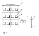
- the Fig. 2 shows a possible embodiment of the arrangement according to the invention, in which the subscriber-side access technology of several the Internet (wide area network) using participants according to the invention on a stationary object 7 is arranged and formed.
- the access technology of a respective subscriber which enables the relevant subscriber to use the Internet by means of at least one computer-based terminal, is integrated into the window of his home or office as part of the shell 6 of the building or fixed object 7.
- the antenna 2 for radio communication with the network access point 1 is arranged on the window pane or within a multiple glazing of the window.
- the other, not shown here in this presentation components of the subscriber-side access technology are, as in Fig. 1 shown or similar, integrated into the window frame of the window.
- the network access point 1 (access point) arranged in relative proximity to the apartment building, that is to say at least in the radio range, corresponds to that in FIG Fig. 1 and is preferably connected via a fiber optic cable to the Internet.
- the Fig. 3 shows an embodiment of the arrangement in which the subscriber-side access technology in the shell 6 'of a mobile object 7', namely in the example in the body of a motor vehicle, is included.
- the antenna 2 is arranged for communication with the network access point or points 1, 1 ', 1 "on a window pane, namely the front pane of the vehicle or within the composite of a safety glazing, wherein the further units of the subscriber-side access technology - which are operated on the antenna 2 for radio-based communication with a fixed network access point transmitting and receiving units 3 and the router device 4 with interface (s) 5 for computer-based terminals - in the enclosure of the antenna 2 receiving windscreen are integrated.
- the object 7 'accommodating the subscriber-side access technology is a mobile object in the illustrated example, several of them are located along the possible movement corridor - in this case the road for the motor vehicle Fig. 1 trained network access points 1, 1 ', 1 "arranged, which pass the subscriber-side access technology during the movement of the vehicle in a handover method to each other.
- Comparable forms of training refer to the inclusion of subscriber-side access technology in the shell of rail vehicles or ships, the latter being of practical relevance, in particular with regard to inland waterway transport.
- the network access points 1, 1 ', 1 are arranged with the direct broadband coupling to the wide area network along a rail track or along a river or canal bank a window of the command bridge of a ship.
Landscapes
- Engineering & Computer Science (AREA)
- Computer Networks & Wireless Communication (AREA)
- Signal Processing (AREA)
- Mobile Radio Communication Systems (AREA)
Priority Applications (1)
| Application Number | Priority Date | Filing Date | Title |
|---|---|---|---|
| EP14165910.2A EP2938158B1 (fr) | 2014-04-24 | 2014-04-24 | Système destiné à la mise à disposition d'accès à large bande pour un réseau de trafic à grande distance |
Applications Claiming Priority (1)
| Application Number | Priority Date | Filing Date | Title |
|---|---|---|---|
| EP14165910.2A EP2938158B1 (fr) | 2014-04-24 | 2014-04-24 | Système destiné à la mise à disposition d'accès à large bande pour un réseau de trafic à grande distance |
Publications (2)
| Publication Number | Publication Date |
|---|---|
| EP2938158A1 true EP2938158A1 (fr) | 2015-10-28 |
| EP2938158B1 EP2938158B1 (fr) | 2019-07-24 |
Family
ID=50555067
Family Applications (1)
| Application Number | Title | Priority Date | Filing Date |
|---|---|---|---|
| EP14165910.2A Active EP2938158B1 (fr) | 2014-04-24 | 2014-04-24 | Système destiné à la mise à disposition d'accès à large bande pour un réseau de trafic à grande distance |
Country Status (1)
| Country | Link |
|---|---|
| EP (1) | EP2938158B1 (fr) |
Citations (4)
| Publication number | Priority date | Publication date | Assignee | Title |
|---|---|---|---|---|
| EP1267583A1 (fr) * | 2000-03-21 | 2002-12-18 | NEC Corporation | Systeme et procede d'installation pour un terminal cellulaire portable de communication par satellite, de type a separation |
| US20050254442A1 (en) * | 2004-05-13 | 2005-11-17 | Widefi, Inc. | Non-frequency translating repeater with detection and media access control |
| EP1601136A1 (fr) * | 2004-05-24 | 2005-11-30 | Alcatel Alsthom Compagnie Generale D'electricite | Routage de données via des points d'acces sans fil pour un réseau ferroviaire |
| US20120213205A1 (en) * | 2011-02-17 | 2012-08-23 | Clear Wireless, Llc | System and method for providing multi network connectivity |
-
2014
- 2014-04-24 EP EP14165910.2A patent/EP2938158B1/fr active Active
Patent Citations (4)
| Publication number | Priority date | Publication date | Assignee | Title |
|---|---|---|---|---|
| EP1267583A1 (fr) * | 2000-03-21 | 2002-12-18 | NEC Corporation | Systeme et procede d'installation pour un terminal cellulaire portable de communication par satellite, de type a separation |
| US20050254442A1 (en) * | 2004-05-13 | 2005-11-17 | Widefi, Inc. | Non-frequency translating repeater with detection and media access control |
| EP1601136A1 (fr) * | 2004-05-24 | 2005-11-30 | Alcatel Alsthom Compagnie Generale D'electricite | Routage de données via des points d'acces sans fil pour un réseau ferroviaire |
| US20120213205A1 (en) * | 2011-02-17 | 2012-08-23 | Clear Wireless, Llc | System and method for providing multi network connectivity |
Non-Patent Citations (2)
| Title |
|---|
| SANFORD J R ET AL: "Facade integrated microstrip patch antennas applied to personal communication networks", UNIVERSAL PERSONAL COMMUNICATIONS, 1992. ICUPC '92 PROCEEDINGS., 1ST I NTERNATIONAL CONFERENCE ON DALLAS, TX, USA 29 SEPT.-1 OCT. 1992, NEW YORK, NY, USA,IEEE, US, 29 September 1992 (1992-09-29), pages 8.05/1 - 08.05/5, XP010060982, ISBN: 978-0-7803-0591-5 * |
| TO-SHIE T ET AL: "Wireless IP Access System (WIPAS) -Broadband Access System by fiber + radio", PERSONAL, INDOOR AND MOBILE RADIO COMMUNICATIONS, 2006 IEEE 17TH INTER NATIONAL SYMPOSIUM ON, IEEE, PI, 11 September 2006 (2006-09-11), pages 1 - 5, XP031462098, ISBN: 978-1-4244-0329-5 * |
Also Published As
| Publication number | Publication date |
|---|---|
| EP2938158B1 (fr) | 2019-07-24 |
Similar Documents
| Publication | Publication Date | Title |
|---|---|---|
| DE102011014559B4 (de) | Orts- und Mobilanpassung drahtloser Zugangspunkte unter Verwendung kartengestützter Navigation | |
| DE10207858A1 (de) | Verfahren und System für die Informationsbereitstellung und Kommunikation in Fahrzeugen | |
| EP2938158B1 (fr) | Système destiné à la mise à disposition d'accès à large bande pour un réseau de trafic à grande distance | |
| DE19704085A1 (de) | Vorrichtung zur drahtlosen Kommunikation zwischen wenigstens zwei Kommunikationsanlagen | |
| DE963244C (de) | Anordnung zur Nachrichtenuebertragung zu einer ortsbeweglichen Station | |
| EP2932615B1 (fr) | Système de télécommunication | |
| Follmann et al. | Smart und/oder partizipativ? | |
| WO2018219656A1 (fr) | Mise à disposition d'une connexion de communication sans fil entre au moins un terminal de communication positionné dans une région d'espace prédéfinie et un réseau de communication | |
| EP0004003A2 (fr) | Système de transmission d'informations | |
| DE102013203134B4 (de) | Kommunikationsvorrichtung und Verfahren zum Austausch von Daten | |
| DE10001252B4 (de) | Überwachungssystem | |
| DE102005063443A1 (de) | Kommunikationszentrale | |
| DE102019104623B4 (de) | Übertragungsanordnung für eine breitbandige Anbindung an ein Weitverkehrsnetz | |
| DE10312663C5 (de) | Kommunikationsvorrichtung und Fahrzeug mit Kommunikationsvorrichtung | |
| EP1993300B1 (fr) | Procédé et dispositif destinés à l'établissement d'une liaison radio entre différents réseaux | |
| DE19618532A1 (de) | Netzungebundene Telekommunikationsanlage | |
| DE102007025343B4 (de) | Kommunikationsendgerät zum Empfangen von Nachrichten, Kommunikationssystem und Verfahren zum Empfangen von Nachrichten | |
| EP1120981A1 (fr) | Système de communication | |
| DE10129740B4 (de) | Übertragungssystem für Interfahrzeug-Kommunikation | |
| DE102015221069A1 (de) | Innenraumleuchte mit integriertem Drahtlosnetzwerkgerät | |
| DE102016113221A1 (de) | Kommunikationsvorrichtung zum Aufbau eines terrestrischen Kommunikationsnetzwerks und Kommunikationsnetzwerk | |
| EP2760239B1 (fr) | Procédé de fonctionnement d'un système radio mobile avec un terminal électronique mobile fonctionnant dans le domaine du terahertz | |
| DE102015204741A1 (de) | Beleuchtungseinheit | |
| EP3326163B1 (fr) | Procédé de transmission de données, émetteur et récepteur avec un appareil de traitement de données | |
| DE102015117335A1 (de) | Anordnung zur Ermöglichung drahtloser Kommunikation in einem begrenzten Raum |
Legal Events
| Date | Code | Title | Description |
|---|---|---|---|
| PUAI | Public reference made under article 153(3) epc to a published international application that has entered the european phase |
Free format text: ORIGINAL CODE: 0009012 |
|
| AK | Designated contracting states |
Kind code of ref document: A1 Designated state(s): AL AT BE BG CH CY CZ DE DK EE ES FI FR GB GR HR HU IE IS IT LI LT LU LV MC MK MT NL NO PL PT RO RS SE SI SK SM TR |
|
| AX | Request for extension of the european patent |
Extension state: BA ME |
|
| 17P | Request for examination filed |
Effective date: 20160428 |
|
| RBV | Designated contracting states (corrected) |
Designated state(s): AL AT BE BG CH CY CZ DE DK EE ES FI FR GB GR HR HU IE IS IT LI LT LU LV MC MK MT NL NO PL PT RO RS SE SI SK SM TR |
|
| STAA | Information on the status of an ep patent application or granted ep patent |
Free format text: STATUS: EXAMINATION IS IN PROGRESS |
|
| 17Q | First examination report despatched |
Effective date: 20170629 |
|
| GRAP | Despatch of communication of intention to grant a patent |
Free format text: ORIGINAL CODE: EPIDOSNIGR1 |
|
| STAA | Information on the status of an ep patent application or granted ep patent |
Free format text: STATUS: GRANT OF PATENT IS INTENDED |
|
| RIC1 | Information provided on ipc code assigned before grant |
Ipc: H04W 88/06 20090101ALN20190117BHEP Ipc: H04W 84/00 20090101ALN20190117BHEP Ipc: H04W 88/04 20090101ALN20190117BHEP Ipc: H04W 84/10 20090101AFI20190117BHEP |
|
| RIC1 | Information provided on ipc code assigned before grant |
Ipc: H04W 88/06 20090101ALN20190118BHEP Ipc: H04W 84/00 20090101ALN20190118BHEP Ipc: H04W 88/04 20090101ALN20190118BHEP Ipc: H04W 84/10 20090101AFI20190118BHEP |
|
| INTG | Intention to grant announced |
Effective date: 20190213 |
|
| GRAS | Grant fee paid |
Free format text: ORIGINAL CODE: EPIDOSNIGR3 |
|
| GRAA | (expected) grant |
Free format text: ORIGINAL CODE: 0009210 |
|
| STAA | Information on the status of an ep patent application or granted ep patent |
Free format text: STATUS: THE PATENT HAS BEEN GRANTED |
|
| AK | Designated contracting states |
Kind code of ref document: B1 Designated state(s): AL AT BE BG CH CY CZ DE DK EE ES FI FR GB GR HR HU IE IS IT LI LT LU LV MC MK MT NL NO PL PT RO RS SE SI SK SM TR |
|
| REG | Reference to a national code |
Ref country code: GB Ref legal event code: FG4D Free format text: NOT ENGLISH |
|
| REG | Reference to a national code |
Ref country code: CH Ref legal event code: EP |
|
| REG | Reference to a national code |
Ref country code: DE Ref legal event code: R096 Ref document number: 502014012262 Country of ref document: DE |
|
| REG | Reference to a national code |
Ref country code: AT Ref legal event code: REF Ref document number: 1159865 Country of ref document: AT Kind code of ref document: T Effective date: 20190815 |
|
| REG | Reference to a national code |
Ref country code: IE Ref legal event code: FG4D Free format text: LANGUAGE OF EP DOCUMENT: GERMAN |
|
| REG | Reference to a national code |
Ref country code: NL Ref legal event code: MP Effective date: 20190724 |
|
| REG | Reference to a national code |
Ref country code: LT Ref legal event code: MG4D |
|
| PG25 | Lapsed in a contracting state [announced via postgrant information from national office to epo] |
Ref country code: HR Free format text: LAPSE BECAUSE OF FAILURE TO SUBMIT A TRANSLATION OF THE DESCRIPTION OR TO PAY THE FEE WITHIN THE PRESCRIBED TIME-LIMIT Effective date: 20190724 Ref country code: NL Free format text: LAPSE BECAUSE OF FAILURE TO SUBMIT A TRANSLATION OF THE DESCRIPTION OR TO PAY THE FEE WITHIN THE PRESCRIBED TIME-LIMIT Effective date: 20190724 Ref country code: SE Free format text: LAPSE BECAUSE OF FAILURE TO SUBMIT A TRANSLATION OF THE DESCRIPTION OR TO PAY THE FEE WITHIN THE PRESCRIBED TIME-LIMIT Effective date: 20190724 Ref country code: PT Free format text: LAPSE BECAUSE OF FAILURE TO SUBMIT A TRANSLATION OF THE DESCRIPTION OR TO PAY THE FEE WITHIN THE PRESCRIBED TIME-LIMIT Effective date: 20191125 Ref country code: BG Free format text: LAPSE BECAUSE OF FAILURE TO SUBMIT A TRANSLATION OF THE DESCRIPTION OR TO PAY THE FEE WITHIN THE PRESCRIBED TIME-LIMIT Effective date: 20191024 Ref country code: LT Free format text: LAPSE BECAUSE OF FAILURE TO SUBMIT A TRANSLATION OF THE DESCRIPTION OR TO PAY THE FEE WITHIN THE PRESCRIBED TIME-LIMIT Effective date: 20190724 Ref country code: FI Free format text: LAPSE BECAUSE OF FAILURE TO SUBMIT A TRANSLATION OF THE DESCRIPTION OR TO PAY THE FEE WITHIN THE PRESCRIBED TIME-LIMIT Effective date: 20190724 Ref country code: NO Free format text: LAPSE BECAUSE OF FAILURE TO SUBMIT A TRANSLATION OF THE DESCRIPTION OR TO PAY THE FEE WITHIN THE PRESCRIBED TIME-LIMIT Effective date: 20191024 |
|
| PG25 | Lapsed in a contracting state [announced via postgrant information from national office to epo] |
Ref country code: IS Free format text: LAPSE BECAUSE OF FAILURE TO SUBMIT A TRANSLATION OF THE DESCRIPTION OR TO PAY THE FEE WITHIN THE PRESCRIBED TIME-LIMIT Effective date: 20191124 Ref country code: LV Free format text: LAPSE BECAUSE OF FAILURE TO SUBMIT A TRANSLATION OF THE DESCRIPTION OR TO PAY THE FEE WITHIN THE PRESCRIBED TIME-LIMIT Effective date: 20190724 Ref country code: ES Free format text: LAPSE BECAUSE OF FAILURE TO SUBMIT A TRANSLATION OF THE DESCRIPTION OR TO PAY THE FEE WITHIN THE PRESCRIBED TIME-LIMIT Effective date: 20190724 Ref country code: AL Free format text: LAPSE BECAUSE OF FAILURE TO SUBMIT A TRANSLATION OF THE DESCRIPTION OR TO PAY THE FEE WITHIN THE PRESCRIBED TIME-LIMIT Effective date: 20190724 Ref country code: GR Free format text: LAPSE BECAUSE OF FAILURE TO SUBMIT A TRANSLATION OF THE DESCRIPTION OR TO PAY THE FEE WITHIN THE PRESCRIBED TIME-LIMIT Effective date: 20191025 Ref country code: RS Free format text: LAPSE BECAUSE OF FAILURE TO SUBMIT A TRANSLATION OF THE DESCRIPTION OR TO PAY THE FEE WITHIN THE PRESCRIBED TIME-LIMIT Effective date: 20190724 |
|
| PG25 | Lapsed in a contracting state [announced via postgrant information from national office to epo] |
Ref country code: TR Free format text: LAPSE BECAUSE OF FAILURE TO SUBMIT A TRANSLATION OF THE DESCRIPTION OR TO PAY THE FEE WITHIN THE PRESCRIBED TIME-LIMIT Effective date: 20190724 |
|
| PG25 | Lapsed in a contracting state [announced via postgrant information from national office to epo] |
Ref country code: PL Free format text: LAPSE BECAUSE OF FAILURE TO SUBMIT A TRANSLATION OF THE DESCRIPTION OR TO PAY THE FEE WITHIN THE PRESCRIBED TIME-LIMIT Effective date: 20190724 Ref country code: RO Free format text: LAPSE BECAUSE OF FAILURE TO SUBMIT A TRANSLATION OF THE DESCRIPTION OR TO PAY THE FEE WITHIN THE PRESCRIBED TIME-LIMIT Effective date: 20190724 Ref country code: IT Free format text: LAPSE BECAUSE OF FAILURE TO SUBMIT A TRANSLATION OF THE DESCRIPTION OR TO PAY THE FEE WITHIN THE PRESCRIBED TIME-LIMIT Effective date: 20190724 Ref country code: EE Free format text: LAPSE BECAUSE OF FAILURE TO SUBMIT A TRANSLATION OF THE DESCRIPTION OR TO PAY THE FEE WITHIN THE PRESCRIBED TIME-LIMIT Effective date: 20190724 Ref country code: DK Free format text: LAPSE BECAUSE OF FAILURE TO SUBMIT A TRANSLATION OF THE DESCRIPTION OR TO PAY THE FEE WITHIN THE PRESCRIBED TIME-LIMIT Effective date: 20190724 |
|
| PG25 | Lapsed in a contracting state [announced via postgrant information from national office to epo] |
Ref country code: IS Free format text: LAPSE BECAUSE OF FAILURE TO SUBMIT A TRANSLATION OF THE DESCRIPTION OR TO PAY THE FEE WITHIN THE PRESCRIBED TIME-LIMIT Effective date: 20200224 Ref country code: SM Free format text: LAPSE BECAUSE OF FAILURE TO SUBMIT A TRANSLATION OF THE DESCRIPTION OR TO PAY THE FEE WITHIN THE PRESCRIBED TIME-LIMIT Effective date: 20190724 Ref country code: CZ Free format text: LAPSE BECAUSE OF FAILURE TO SUBMIT A TRANSLATION OF THE DESCRIPTION OR TO PAY THE FEE WITHIN THE PRESCRIBED TIME-LIMIT Effective date: 20190724 Ref country code: SK Free format text: LAPSE BECAUSE OF FAILURE TO SUBMIT A TRANSLATION OF THE DESCRIPTION OR TO PAY THE FEE WITHIN THE PRESCRIBED TIME-LIMIT Effective date: 20190724 |
|
| REG | Reference to a national code |
Ref country code: DE Ref legal event code: R097 Ref document number: 502014012262 Country of ref document: DE |
|
| PLBE | No opposition filed within time limit |
Free format text: ORIGINAL CODE: 0009261 |
|
| STAA | Information on the status of an ep patent application or granted ep patent |
Free format text: STATUS: NO OPPOSITION FILED WITHIN TIME LIMIT |
|
| PG2D | Information on lapse in contracting state deleted |
Ref country code: IS |
|
| 26N | No opposition filed |
Effective date: 20200603 |
|
| PG25 | Lapsed in a contracting state [announced via postgrant information from national office to epo] |
Ref country code: SI Free format text: LAPSE BECAUSE OF FAILURE TO SUBMIT A TRANSLATION OF THE DESCRIPTION OR TO PAY THE FEE WITHIN THE PRESCRIBED TIME-LIMIT Effective date: 20190724 |
|
| PG25 | Lapsed in a contracting state [announced via postgrant information from national office to epo] |
Ref country code: MC Free format text: LAPSE BECAUSE OF FAILURE TO SUBMIT A TRANSLATION OF THE DESCRIPTION OR TO PAY THE FEE WITHIN THE PRESCRIBED TIME-LIMIT Effective date: 20190724 |
|
| REG | Reference to a national code |
Ref country code: CH Ref legal event code: PL |
|
| PG25 | Lapsed in a contracting state [announced via postgrant information from national office to epo] |
Ref country code: LU Free format text: LAPSE BECAUSE OF NON-PAYMENT OF DUE FEES Effective date: 20200424 Ref country code: LI Free format text: LAPSE BECAUSE OF NON-PAYMENT OF DUE FEES Effective date: 20200430 Ref country code: CH Free format text: LAPSE BECAUSE OF NON-PAYMENT OF DUE FEES Effective date: 20200430 |
|
| REG | Reference to a national code |
Ref country code: BE Ref legal event code: MM Effective date: 20200430 |
|
| PG25 | Lapsed in a contracting state [announced via postgrant information from national office to epo] |
Ref country code: BE Free format text: LAPSE BECAUSE OF NON-PAYMENT OF DUE FEES Effective date: 20200430 |
|
| PG25 | Lapsed in a contracting state [announced via postgrant information from national office to epo] |
Ref country code: IE Free format text: LAPSE BECAUSE OF NON-PAYMENT OF DUE FEES Effective date: 20200424 |
|
| REG | Reference to a national code |
Ref country code: AT Ref legal event code: MM01 Ref document number: 1159865 Country of ref document: AT Kind code of ref document: T Effective date: 20200424 |
|
| PG25 | Lapsed in a contracting state [announced via postgrant information from national office to epo] |
Ref country code: AT Free format text: LAPSE BECAUSE OF NON-PAYMENT OF DUE FEES Effective date: 20200424 |
|
| PG25 | Lapsed in a contracting state [announced via postgrant information from national office to epo] |
Ref country code: MT Free format text: LAPSE BECAUSE OF FAILURE TO SUBMIT A TRANSLATION OF THE DESCRIPTION OR TO PAY THE FEE WITHIN THE PRESCRIBED TIME-LIMIT Effective date: 20190724 Ref country code: CY Free format text: LAPSE BECAUSE OF FAILURE TO SUBMIT A TRANSLATION OF THE DESCRIPTION OR TO PAY THE FEE WITHIN THE PRESCRIBED TIME-LIMIT Effective date: 20190724 |
|
| PG25 | Lapsed in a contracting state [announced via postgrant information from national office to epo] |
Ref country code: MK Free format text: LAPSE BECAUSE OF FAILURE TO SUBMIT A TRANSLATION OF THE DESCRIPTION OR TO PAY THE FEE WITHIN THE PRESCRIBED TIME-LIMIT Effective date: 20190724 |
|
| PGFP | Annual fee paid to national office [announced via postgrant information from national office to epo] |
Ref country code: FR Payment date: 20230417 Year of fee payment: 10 Ref country code: DE Payment date: 20230418 Year of fee payment: 10 |
|
| PGFP | Annual fee paid to national office [announced via postgrant information from national office to epo] |
Ref country code: GB Payment date: 20230420 Year of fee payment: 10 |