EP2937634A1 - Dunstabzugshaube mit auszugselement und beleuchtungseinheit und griffelement für dunstabzugshaube - Google Patents
Dunstabzugshaube mit auszugselement und beleuchtungseinheit und griffelement für dunstabzugshaube Download PDFInfo
- Publication number
- EP2937634A1 EP2937634A1 EP15162652.0A EP15162652A EP2937634A1 EP 2937634 A1 EP2937634 A1 EP 2937634A1 EP 15162652 A EP15162652 A EP 15162652A EP 2937634 A1 EP2937634 A1 EP 2937634A1
- Authority
- EP
- European Patent Office
- Prior art keywords
- extractor hood
- pull
- extractor
- lighting unit
- hood
- Prior art date
- Legal status (The legal status is an assumption and is not a legal conclusion. Google has not performed a legal analysis and makes no representation as to the accuracy of the status listed.)
- Granted
Links
Images


Classifications
-
- F—MECHANICAL ENGINEERING; LIGHTING; HEATING; WEAPONS; BLASTING
- F24—HEATING; RANGES; VENTILATING
- F24C—DOMESTIC STOVES OR RANGES ; DETAILS OF DOMESTIC STOVES OR RANGES, OF GENERAL APPLICATION
- F24C15/00—Details
- F24C15/20—Removing cooking fumes
- F24C15/2064—Removing cooking fumes illumination for cooking hood
-
- F—MECHANICAL ENGINEERING; LIGHTING; HEATING; WEAPONS; BLASTING
- F24—HEATING; RANGES; VENTILATING
- F24C—DOMESTIC STOVES OR RANGES ; DETAILS OF DOMESTIC STOVES OR RANGES, OF GENERAL APPLICATION
- F24C15/00—Details
- F24C15/20—Removing cooking fumes
- F24C15/2078—Removing cooking fumes movable
- F24C15/2092—Removing cooking fumes movable extendable or pivotable
Definitions
- the present invention relates to an extractor hood with extract element, handle element and lighting unit and a handle element for an extractor hood.
- a pull-out element displaceable relative to the extractor housing is provided. If this pull-out element is pulled forward in the direction of the user, then the area over which fumes and vapors can be sucked into the extractor housing can be increased.
- a handle element is arranged, on which the user can grab the extract element.
- the space in the extension element is limited in flat-panel hoods.
- This space is also largely used by one or more filter elements or air guide elements.
- the illumination is currently arranged at the rear of the flat-panel hood in flat-panel hoods. This position of the illumination, in particular when using LEDs in conjunction with downstream optical lenses spans a very sharp illuminated space.
- Object of the present invention is therefore to overcome the disadvantages of the prior art and to provide an extractor hood with at least one pullout element, a handle member and at least one lighting unit, which allows a simple and reliable way large-scale illumination of at least the cooking area and possibly adjacent areas.
- the object of the invention is achieved by an extractor hood with a arranged in the lower region of the extractor housing holder, at least one extractable in the holder extractable element, which has guides on the sides and at least one handle element has on the front.
- the extractor hood according to the invention is characterized in that at least one lighting unit is provided in the front region of the at least one extract element.
- the front here refers to the page that faces the user, even if it is not visible to the user.
- a wall-mounted and / or housed in a wall unit hood is therefore understood as the front side, which faces away from the mounting wall.
- an extractor hood is a device for extracting fumes and vapors, in particular for use via hotplates, which has an extractor housing in which at least one fan and / or fan, in particular in a fan housing, is arranged.
- the extractor hood according to the invention is a flat screen hood.
- the lower area of the extractor housing is understood to mean the area which at the bottom of the Extractor housing adjacent, that is located below the extractor housing or the area that extends at least partially over the lower part of the extractor housing.
- the extractor hood according to the invention comprises at least one extract element.
- the at least one extension element has a base body and is preferably flat. This body is bounded by two side surfaces, the front and the back. Between these surfaces extend the top and bottom of the pullout element.
- the front of the extract element the side of the extract element is referred to, which faces the user.
- the back of the extract element faces away from the user and is facing the mounting wall in a wall-mounted hood.
- the area in front, at and behind the front of the main body of the pull-out element is designated under the front area of the pull-out element.
- the region of the extension element which extends from the front of the main body of the extension element to half the length of the extension element away from the user back, a front portion of the pullout element is.
- the front region of the pull-out element also includes the at least one grip element.
- the gripping element can lie in front of the front side of the main body of the drawer element and form the front side of the drawer element.
- the top of the at least one extractor element points after installation in the extractor hood in the direction of the extractor housing, the underside faces in the direction of the hob.
- the extraction element preferably has at least one inlet opening for the intake of fumes and vapors.
- at least one filter element is preferably provided in the pull-out element.
- Guides are arranged on the sides, for example on the side surfaces of the basic body, of the at least one extract element. These may be formed for example by rails or by the Side surfaces of the body of the extract element itself be formed.
- an air guide element which can also be provided as a vapor guide element and which, for example, can constitute a glass plate, can be provided in the extension element. If only one or more air guide elements are provided in the pull-out element and no filter element, the inlet opening in the pull-out element can be dispensed with. In this case, the vapor is passed along the extraction element and directed to an inlet opening in the extractor housing.
- pulling out and pushing in the at least one pull-out element means that the pull-out element is moved in the direction of the user or moved away from the user.
- the at least one extract element is displaceable in the horizontal direction.
- the pull-out element is displaced in a direction deviating from the horizontal direction, in particular in a direction inclined thereto.
- the front portion of the extractor element In the retracted state, the front portion of the extractor element has a minimum distance to the rear of the extractor hood. When pulling out, the distance between the extension element and the rear wall of the extractor hood increases in comparison to the inserted state.
- a holder is arranged, which is provided for receiving the at least one extractable element.
- the holder can be formed of several components.
- the holder may also be integrated in the extractor housing, for example, be formed by folds of the lower edges of the side walls of the extractor housing.
- the holder has two profile strips. As a profile strip at least a part of the holder is referred to, by means of which the at least one extract element is held and guided on the extractor hood.
- the lateral guides of the at least one extension element are held by the profile strips.
- the holder is arranged in the lower region of the extractor housing and can thus rest against the extractor housing from below or be formed by the extractor housing. According to the invention, the holder is in such arranged at the bottom of the extractor housing, that the at least one, recorded in the holder extract element can be pulled out and inserted without or with little resistance between extract element and extractor housing.
- the pull-out element is preferably received in the holder and configured such that in the extended state of the pull-out element, air flowing to or into the pull-out element can be conducted into the interior of the extractor hood.
- a handle element is arranged on the at least one pull-out element of the extractor hood.
- a handle element is understood to be an area in the front part of the main body of the at least one pull-out element or an extension arranged on the front side of the main body of the at least one pull-out element.
- the gripping elements is a component which is separate from the main body of the drawer element and which is connected to the main body, in particular being fastened to the front side of the main body of the drawer element.
- the grip element is used according to the invention for pulling out the pullout element.
- the grip element which is designed as a separate component, can also serve to veneer the main body of the pullout element and at least one part of the extractor housing.
- the gripping element when the gripping element is provided in the front region of the main body of the drawer element, the gripping element is preferably configured integrally with the main body of the drawer element or formed in this.
- a recess in the bottom of the main body of the pull-out element can be introduced as a handle element.
- the grip element which is provided on the front side of the basic body of the pull-out element, extends beyond at least one side of the main body of the pull-out element. It is therefore within the scope of the invention that extends the handle member on at least one side of the main body of the extension element on the main body of the drawer element laterally or on the top or bottom of the main body of the drawer element upwards or downwards over the main body of the drawer element.
- the projection of the handle member in the retracted position of the pullout element preferably covers a portion of the front of the extractor housing, in particular at least one between the main body of the pullout element and the holder or a part the holder of the extractor housing existing gap from.
- the at least one gripping element is, for example, a handle, a gripping strip or a recessed grip. Also, the use of a combination of two or more of these types of handle elements is within the scope of the present invention.
- a lighting unit is arranged in the front region of the at least one extract element of the extractor hood.
- the lighting unit which is also referred to below as the lighting element, comprises at least one light source.
- the lighting unit may comprise at least one holder for the lighting means and at least one contact point for the connection of the lighting means to a control unit, by means of which the voltage supply of the contact point and operating states of the lighting unit can be adjusted and preferably regulated.
- the operating state of the lighting unit is understood in the context of the invention, the switching on and off as well as the dimming of the bulb.
- a possible color control of the lighting device or lighting means is also understood. This color control relates in particular to the RGB control of LED lights of different colors to produce different shades by additive RGB color mixing and the setting of, for example, warm or cold white lighting.
- the at least one lighting unit is arranged in the front region of the at least one pull-out element.
- the lighting unit is arranged such that the lighting means can be aligned with the cooking area, which is also referred to as a cooktop, and adjacent areas such as work surfaces. Therefore, the lighting unit is preferably provided in the bottom of the pull-out element. Due to the inventive arrangement of a lighting unit in the front region of the at least one extract element, a lighting of the front portion of the cooktop and adjacent areas is made possible. By the lighting unit (s) are provided on the pullout element and this can be pulled out to the front of the extractor housing, the area that can be illuminated below the hood, moved forward and / or enlarged. The light source can be directed vertically downwards in the extractor hood.
- An illumination behind areas below the hood can be done by the light source is aligned with these areas, that is inclined in the extract element is introduced. It is particularly advantageous here that the user is not dazzled by the orientation of the lighting down or on rear areas. The user sees with the light and if he stands centrally in front of the hood, he throws in the case of backward room lighting not such a large shadow. A dark area, which would otherwise exist in the front part of the cooking area is lit and pots, especially harnesswandige are illuminated.
- the arrangement of the at least one lighting unit in the front region of the pull-out element has the advantage that the remaining surface of the at least one pull-out element that is not occupied by a lighting unit is connected. This continuous surface thus has no interruptions by lighting units and can be equipped with at least one filter element.
- a further advantage of the arrangement according to the invention of the at least one lighting unit in the front region of the pull-out element is that a limitation of the suction or filter function in the extractor hood by the lighting units is not to be feared.
- a limitation of these functions for example, especially in flat-screen hoods occur when the space required for the installation of lighting is at the expense of the filter surface.
- a frame forming the base body of the pull-out element or a separate component on the front side of the base body can be used to hold the lighting unit (s), so that those available for filters or air guiding elements standing area is not affected.
- the production of the extractor hood and in particular of the pull-out element with lighting unit (s) is simplified since given components, such as the frame of the main body of the pull-out element or a handle element for receiving or attaching the lighting units can be used.
- the advantages of the present invention can be used especially in the extractor hood, which is a flat screen hood and thus provides only a very limited space in the extract element available.
- the handle element can be permanently connected to the pull-out element or be formed in this. According to a preferred embodiment, however, the at least one handle element is detachably connected to the at least one pull-out element. Detachably connected in this context means that the connection between the handle element and the pull-out element can be separated without destruction for both the pull-out element and for the handle element. According to the invention, a renewed attachment of this grip element as well as an attachment of another grip element, ie a replacement, after releasing the connection is possible.
- a detachable connection between the handle element and the extension element allows replacement of the handle element for aesthetic reasons. According to the taste of the time or in the case of redesigning the kitchen equipment, the user may need to replace the stylus member as needed. Furthermore, the detachable connection between the handle element and the pull-out element also makes it possible to remove the handle element in the event of wear or damage.
- connection elements are provided on the extension element and / or on the handle bar.
- Suitable connecting means are known in the art and may be, for example, screws and / or bolts with the corresponding counterparts such as bore and sleeve.
- detachable adhesive or adhesive compounds can be used according to the invention as connecting means. Additionally or alternatively, latching or sliding connections can also be used.
- the at least one lighting unit is arranged on the at least one gripping element.
- the grip element in the sense of the invention, both an attachment of the illumination unit on the outside to the grip element and also an at least partial introduction of the illumination unit into the grip element are understood.
- an opening is provided in the grip element, via which light can be emitted by the illumination unit.
- the lighting unit is provided on or in the underside of the handle element.
- This embodiment of the invention in which the at least one lighting unit is arranged on the at least one grip element, is particularly advantageous because the grip element is arranged in a region of the pull-out element which is not provided for receiving filter elements.
- the installation of a lighting unit therefore does not lead to a reduction of the area provided as a filter surface in a pull-out element.
- the handle element is usually not covered by other parts of the hood down in the retracted state of the extract element.
- the lighting of the hood which is generated by the lighting unit (s) in the handle element, can be used, even if the pullout element is not pulled out for operation, but is fully inserted.
- the stylus element is detachably connected to the pull-out element and the at least one lighting unit is arranged on the handle element.
- This embodiment is particularly advantageous because a possible replacement of the stylus element also enables an exchange or a temporary removal of the at least one illumination element.
- a temporary removal of the stylus element can be advantageous, for example, in order to carry out a repair on the illumination unit or an exchange of illuminants arranged on the illumination unit on the at least one illumination unit arranged on the grip element.
- the user can use handle strips with different lighting units by personal choice. So the user can for example, use between handles with different bulbs or with a different number of lighting units. This also makes it possible to respond to a possibly occurring in the cooking area change the lighting conditions by selecting a corresponding handle element.
- a handle bar represents, for example, a hollow profile, in particular an extruded profile.
- the handle strip is made separately from the pullout element and the introduction of openings for the lighting unit (s) and the introduction of the lighting unit (s) itself can therefore be made easier.
- the position of the lighting unit (s) can be flexibly selected in a handle element that represents a handle.
- the lighting unit (s) are preferably provided in or on the underside of the handle. Does the handle bar but a height that is greater than the height of the body of the drawer element and thus there is a supernatant of the handle bar on the body down, the lighting unit may for example also be provided in or on the back of the handle. In this way, on the one hand, the lighting unit is prevented from becoming dirty and, on the other hand, an alignment of the light cone which is emitted by the lighting unit can be easily realized to the rear.
- At least one further lighting unit which is arranged in the front, middle or rear area of the extractor hood, is provided on the extractor hood.
- This further illumination unit is referred to below as a light unit in order to better distinguish it from the illumination device provided according to the invention in the front region of the extension element. Due to the arrangement of at least one light unit, a further area of the cooking area and / or adjacent work surface can be specifically illuminated.
- This at least one light unit may be arranged such that it is visible only in the partially or completely pulled out state of the at least one extract element.
- the Light unit may be provided, for example, on the pullout element.
- the at least one light unit can be arranged in each area of the extract element, depending on which area of the room is to be illuminated under the extractor hood. According to one embodiment, the at least one light unit is arranged on the underside of the at least one pull-out element. As an alternative or in addition to at least one light unit on the pullout element, one or more light units can also be provided on the extractor housing or on a further part of the extractor hood. The light unit is preferably arranged in the rear region of the extractor hood. In this way, in the inventive arrangement of at least one illumination device in the front region of the extension element, a uniform large-area illumination of the space below the extractor hood can be achieved.
- the at least one lighting unit preferably comprises a lighting means, which is an LED, halogen lamp or incandescent lamp.
- the light unit may also have light sources of this type.
- the light source arranged in the at least one lighting unit is a light emitting diode (LED), which is also referred to below as an LED lamp, or an arrangement of LED lamps.
- LED light emitting diode
- LEDs have the advantage over conventional light sources, such as halogen lamps, that the emission characteristic is substantially more concentrated and generally amounts to approximately 120 °.
- LEDs are advantageous because they have a relatively small size.
- additional LEDs in the extract element bring a significant advantage for the user of the hood.
- LED lamps are also particularly advantageous because the LED lamps can be operated according to the invention in a load range in which no complex cooling is necessary. Furthermore, in the use of LED lamps may be dispensed with a complex straightening optics if necessary. However, a directing optics can be provided if the arrangement of the LED lamps and the desired illumination make this necessary.
- the at least one lighting unit has cooling elements and / or light rays directing optical elements.
- the arrangement of cooling elements is provided when the lamps have a heat radiation, which could lead to overheating of the at least one extract element or an element used therein, such as a filter element.
- Light-beam directing optical elements, such as lenses or reflectors, according to the invention are then preferably provided in the at least one lighting unit when the emission characteristic of the light source is to be changed. This will be necessary in particular when incandescent or halogen lamps are used as the illuminant.
- At least one filter element is provided in the pull-out element, which covers the underside of the main body of the pull-out element or a part of the underside of the main body of the pull-out element.
- the at least one filter element is used for the separation and optionally absorption of particles and / or odors from the intake air.
- Suitable filter elements are known in the art and may, for example, constitute a filter cassette made of expanded metal.
- activated carbon can be provided as an absorbent in the filter element or in a separate filter element. It is within the scope of the invention to combine various filter elements.
- an air guide element can also be provided in the extension element, via which air is directed directed to an air inlet opening of the extractor housing.
- the air guide element can be for example a disk or plate which is provided in the main body of the pull-out element.
- the at least one lighting unit is arranged in a pull-out element with filter element or air guide in front of the filter element or air guide.
- the lighting unit may be provided for example in the front part of the filter element or air guide element holding frame. Additionally or alternatively, however, the illumination device can also be provided in this embodiment on a handle bar, which is arranged in front of the frame of the filter element or air guide element.
- the extractor hood in the holder on a planar, statically arranged element which covers the base of the extractor element in its retracted state on the side facing away from the extractor housing side partially or completely.
- the statically arranged element may for example represent a filter element or an air guide element in the form of a disk or plate.
- the extension element is in this embodiment above the statically arranged element.
- This embodiment of the invention is advantageous because the at least one extract element is protected from below when fully or partially covered by the statically arranged element. Thus, clogging of a filter element of the pullout element in the retracted state of the pullout element can be prevented. It is also advantageous that due to the different possibilities of designing the statically arranged element with respect to color and material, an individualization of the extractor hood according to the invention can be carried out. According to the material selection for the static element taking into account the prevailing in the cooking area environmental conditions such as humidity, heat and fat enrichment.
- an embodiment of the extractor hood according to the invention in which an operating module for actuating the at least one lighting unit and / or the extractor hood is arranged in the front region of the pull-out element and in particular in the at least one handle element.
- the arrangement of the operating module in the at least one gripping element of the at least one extract element is particularly advantageous because the stylus element is located in the front region of the extract element. This makes the operating module easily accessible to the user standing in front of the hood. Even in the retracted state of the extension element, it is possible for the user to reach the operating module.
- the operating module is preferably arranged on the underside, the front or the upper side of the front region of the pull-out element.
- both the extractor hood and the at least one lighting unit can be actuated by means of the control module arranged in the handle element.
- the control module arranged in the handle element.
- only the at least one lighting unit or the extractor hood can be actuated by means of this operating module.
- further control modules are arranged at different positions on the hood.
- all lighting units can be operated separately or jointly by means of the operating module arranged in the grip element.
- the arrangement of the operating module in the front region of the pull-out element is advantageous in the extractor hood according to the invention, in particular for the reason that the operating module is thereby located in the vicinity of the lighting unit (s). Thus, the cost of wiring the lighting unit (s) is reduced.
- the power supply of the at least one lighting unit can take place via an operating module of the extractor hood, in particular via the operating element provided in the gripping element.
- the control element for example, 1-2 watts of lighting and in particular the lighting unit can be added in the front of the extract element. This simplifies the structure of Extractor hood on, since a separate power supply for the lighting unit (s) does not need to be provided.
- the power supply of the lighting unit can also be made from the general power supply of the hood or the power supply of the general lighting of the hood, such as the light unit.
- the object of the invention is further achieved by the provision of a gripping element, for connection to the at least one extract element of a cooker hood according to the invention.
- At least one contact interface for the electrical contact to the extractor hood is provided on the gripping element according to the invention.
- This at least one contact interface may permit electrical contact between a control module arranged in the grip element and / or a lighting unit arranged in the grip element with the extractor hood.
- the advantages of a detachable gripping element can be utilized.
- the possibility of the user to replace a arranged on the hood handle element can be done for aesthetic or technical reasons. For aesthetic reasons, a replacement will take place when the user wants to adapt the stylus element of the hood, for example, to a different design of the kitchen.
- the contact interface may be, for example, a plug or a female connector.
- the contact interface on the handle element may, for example, constitute a contact surface which comes into contact with contact pins on the front side of the main body of the extension element when the grip element is fastened to the base body.
- contact is established via the at least one contact interface for the electrical contact between a lighting unit arranged in the grip element and the extractor hood.
- the gripping element in which at least one illumination unit is arranged in the stylus element and the illumination unit comprises at least one LED lamp as the illuminant.
- the at least one handle element comprises more than one LED lamp.
- the grip element can be equipped with a separate light switch.
- the at least one lighting unit arranged in the grip element is connected to the general lighting circuit of the extractor hood.
- an embodiment of the invention is advantageous in which the at least one lighting unit is equipped in the front region of the extractor element of the extractor hood by means of a separate light switch.
- the at least one lighting unit is connected to the general lighting circuit in the front region of the extractor hood.
- FIG. 2 is shown a side view of a hood of the prior art.
- the shown extractor hood of the prior art is a flat screen hood.
- the hood is arranged above a hob 9.
- the extractor hood consists of a fume hood housing 4, in the lower region of a holder in the form of moldings 3 is provided.
- a vent pipe 5 also can be removed via the air from the extractor housing 4.
- a blower or fan in FIG. 2 not visible.
- an extract element 1 is guided.
- the pull-out element 1 on the sides guides 12.
- FIG. 2 is the pullout element 1 shown in the pulled-out state.
- a grip element 2 is arranged at the front of the pullout element 1.
- a light unit 6 is arranged in the rear region of the extractor hood, which has an LED lamp in the illustration shown.
- the light unit 6 is provided on the extractor housing 4 or on the holder 3 of the extractor housing 4. Schematically, the light cone 7 is shown, which is thrown by the light unit 6 on the hob 9.
- FIG. 1 shows an embodiment of the present invention.
- the construction of in FIG. 1 shown extractor hood essentially corresponds to the structure of in FIG. 2 shown extractor hood.
- a lighting unit 11 may in particular comprise one or more LED lamps.
- a light unit 6 is provided.
- the illumination of the hob 9 is shown schematically when both the rear light unit 6 and the front lighting unit 11 illuminate the hob 9.
- the directed light cone 7 of the rear light unit 6 is supplemented by the additional light cone 10 of the lighting unit 11 to a total illumination of the cooking area and adjacent areas.
- FIG. 3 shows an embodiment of the extractor hood according to the invention in a perspective bottom view.
- four illumination units 11 are provided in the lower region of the grip element 2 of the pull-out element 1.
- the number and distribution of the lighting units 11 is not limited to the number and distribution shown.
- an operating element 14 is arranged in the grip element 2.
- the operating element 14 is provided in the illustrated embodiment in the front of the handle element 2, which represents a handle bar.
- a filter element 13 which occupies the entire underside of the main body of the pull-out element 1 and is releasably held in a frame.
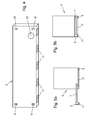
- FIG. 4 an embodiment of a handle element 2 according to the invention is shown in a rear view, that is shown with the mounted state in the side facing away from the user to the front.
- five lighting units 11 are arranged on the underside of the handle element 2 .
- the contact interface 15 for the electrical contact to the extractor hood is arranged in this view in the lower region of the grip element 2 at its rear side.
- the contact interface 15 is arranged elsewhere on the grip element 2.
- Connecting elements 16 are each arranged in the corners of the illustrated back of the grip element 2. The arrangement of more However, connecting elements or their arrangement at another position is also within the scope of the invention.
- FIG. 5 a further embodiment of the extractor hood according to the invention is shown schematically.
- the lower end of the extractor housing 4 is limited by a static element 17, which may for example constitute a filter element.
- the static element 17 is immovably connected to the extractor housing 4 or another part of the extractor hood.
- the pull-out element 1 is arranged parallel to the static element 17.
- a handle element 2 is provided in the form of a handle.
- a lighting unit 11 is provided at the bottom of the handle bar 2, a lighting unit 11 is provided.
- a light unit 6 is provided in the rear area of the extractor hood, for example on the static element 17 or behind the static element 17.
- FIG. 5a shows the pullout element 1 in the extended state.
- the main body of the pull-out element 1 is not covered by the static element 17.
- the illumination of the room below the extractor hood corresponds in this condition to the in FIG. 1 Illumination shown by means of a rear-directed and a front, preferably downwardly directed, additional light cone 7, 10th
- FIG. 5b the pull-out element 1 is shown in the inserted state.
- the main body of the pull-out element is concealed downward by the static element 17.
- the handle bar 2 is also in the inserted state in front of the static element 17.
- light from the illumination unit 11 are delivered to the handle bar down.
- light unit 6 light can be emitted in this state.
- the present invention provides an extractor hood, which particularly advantageously enables the illumination of the hob or cooktop and adjacent areas below an extract element.
- at least one lighting element is arranged in the front region of the pull-out element.
- LED lamps are used as the light source, which have an advantageous radiation characteristic. The fact that the user standing in front of the cooker hood looks at the light is another advantage.
- the gripping element provided according to the invention in which lighting elements are arranged, combines the abovementioned advantages according to the invention with great variability for the user.
- the handle element according to the invention can be equipped, for example, with LED lamps according to the customer's request.
- An exchange of the handle element by a handle element with a different design and / or other bulbs makes it possible to meet individual customer requirements.
- An adaptation of the lighting of the hood to changing lighting conditions or a changed furnishing of the kitchen is thus user-friendly guaranteed.
- a handle element can be mounted in changed light conditions, in which compared to the original handle element more lighting elements are arranged, in which more bulbs are provided.
Landscapes
- Engineering & Computer Science (AREA)
- Chemical & Material Sciences (AREA)
- Combustion & Propulsion (AREA)
- Mechanical Engineering (AREA)
- General Engineering & Computer Science (AREA)
- Ventilation (AREA)
- Arrangement Of Elements, Cooling, Sealing, Or The Like Of Lighting Devices (AREA)
- Mechanical Means For Catching Fish (AREA)
- Circuit Arrangement For Electric Light Sources In General (AREA)
Abstract
Description
- Die vorliegende Erfindung betrifft eine Dunstabzugshaube mit Auszugselement, Griffelement und Beleuchtungseinheit sowie ein Griffelement für eine Dunstabzugshaube.
- Im Stand der Technik sind verschiedene Arten von Dunstabzugshauben bekannt. Bei den so genannten Flachschirmhauben ist ein gegenüber dem Dunstabzugsgehäuse verschiebbares Auszugselement vorgesehen. Wird dieses Auszugselement nach vorne in Richtung auf den Benutzer herausgezogen, so kann die Fläche, über welche Dünste und Wrasen in das Dunstabzugsgehäuse eingesaugt werden können, vergrößert werden. An Dunstabzugshauben mit Auszugselement ist üblicherweise ein Griffelement angeordnet, an welchem der Benutzer das Auszugselement greifen kann.
- Weiterhin sind im Stand der Technik Dunstabzugshauben mit Beleuchtung bekannt. Die Lösungen des Standes der Technik in Bezug auf die Beleuchtung an Dunstabzugshauben sind jedoch nicht immer befriedigend. So werden beispielsweise aufgrund von durch die Bauart der Dunstabzugshauben bedingten räumlichen Beschränkungen die Beleuchtungsmittel häufig nicht optimal für die Ausleuchtung der Kochmulde und angrenzender Bereiche positioniert.
- Darüber hinaus ist bei Flachschirmhauben der Bauraum in dem Auszugselement begrenzt. Dieser Bauraum wird zudem weitestgehend durch eines oder mehrere Filterelemente oder Luftleitelemente in Anspruch genommen. Aus diesem Grund ist bei Flachschirmhauben die Beleuchtung derzeit im hinteren Bereich der Flachschirmhaube angeordnet. Durch diese Position der Beleuchtung wird insbesondere bei Verwendung von LEDs in Verbindung mit nachgelagerten optischen Linsen ein sehr scharfer beleuchteter Raum aufgespannt.
- Da die Beleuchtung aber von hinten erfolgt, ist der Lichtkegel im vorderen Bereich nicht sehr hoch. Sobald der Benutzer der Dunstabzugshaube aus dem Lichtkegel herauskommt, beispielsweise bei Vorbereitungsarbeiten für den Kochvorgang wie beim Gemüseputzen, steht er buchstäblich im Dunkeln.
- Aufgabe der vorliegenden Erfindung ist es deshalb, die Nachteile des Standes der Technik zu überwinden und eine Dunstabzugshaube mit mindestens einem Auszugselement, einem Griffelement und mindestens einer Beleuchtungseinheit bereitzustellen, welche auf einfache und zuverlässige Weise eine großflächige Ausleuchtung zumindest des Kochbereichs und gegebenenfalls angrenzender Bereiche ermöglicht.
- Die Aufgabe der Erfindung wird gelöst durch eine Dunstabzugshaube mit einer im unteren Bereich des Dunstabzugsgehäuses angeordneten Halterung, mindestens einem in der Halterung ausziehbar aufgenommenen Auszugselement, das an den Seiten Führungen besitzt und an der Vorderseite mindestens ein Griffelement aufweist. Die erfindungsgemäße Dunstabzugshaube ist dadurch gekennzeichnet, dass im vorderen Bereich des mindestens einen Auszugselements mindestens eine Beleuchtungseinheit vorgesehen ist.
- Richtungsangaben, wie beispielsweise vorne, hinten, oben, unten oder seitlich werden im Folgenden, sofern nicht anders angegeben, bezüglich einer Dunstabzugshaube im eingebauten Zustand verstanden. Vorne bezeichnet hierbei die Seite, die dem Benutzer zugewandt ist, auch wenn diese für den Benutzer gegebenenfalls nicht sichtbar ist. Bei einer wandmontierten und/oder in einem Oberschrank aufgenommenen Dunstabzugshaube wird als Vorderseite daher die Seite verstanden, die der Montagewand abgewandt ist.
- Als Dunstabzugshaube wird im Sinne der vorliegenden Erfindung eine Vorrichtung zum Absaugen von Dünsten und Wrasen insbesondere zur Verwendung über Kochstellen bezeichnet, welche ein Dunstabzugsgehäuse aufweist, in welchem zumindest ein Gebläse und/oder ein Lüfter, insbesondere in einem Lüftergehäuse, angeordnet ist. Die Dunstabzugshaube stellt erfindungsgemäß eine Flachschirmhaube dar.
- Unter dem unteren Bereich des Dunstabzugsgehäuses wird im Zusammenhang der vorliegenden Erfindung der Bereich verstanden, welcher unten an das Dunstabzugsgehäuse angrenzt, das heißt sich unterhalb der Dunstabzugsgehäuses befindet oder der Bereich, der sich zumindest bereichsweise über den unteren Teil des Dunstabzugsgehäuses erstreckt.
- Die erfindungsgemäße Dunstabzugshaube umfasst mindestens ein Auszugselement. Das mindestens eine Auszugselement weist einen Grundkörper auf und ist vorzugsweise eben ausgebildet. Dieser Grundkörper wird von zwei Seitenflächen, der Vorderseite und der Rückseite begrenzt. Zwischen diesen Flächen erstrecken sich Oberseite und Unterseite des Auszugselements. Als Vorderseite des Auszugselements wird die Seite des Auszugselements bezeichnet, welche dem Benutzer zugewandt ist. Die Rückseite des Auszugselements weist vom Benutzer weg und ist bei einer wandmontierten Dunstabzugshaube der Montagewand zugewandt.
- Unter dem vorderen Bereich des Auszugselements wird im Sinne der Erfindung der Bereich vor, an und hinter der Vorderseite des Grundkörpers des Auszugselementes bezeichnet. Insbesondere stellt auch der Bereich des Auszugselementes, der sich von der Vorderseite des Grundkörpers des Auszugselements bis zur halben Länge des Auszugselements von Benutzer weg nach hinten erstreckt, einen vorderen Bereich des Auszugselementes dar. Unter der Länge des Auszugselements wird vorliegend die Länge der zwischen Vorderseite und Rückseite des Auszugselements verlaufenden Senkrechten in der Fläche des Auszugselementes verstanden. Weiterhin schließt der vordere Bereich des Auszugselements auch das mindestens eine Griffelement ein. Das Griffelement kann hierbei vor der Vorderseite des Grundkörpers des Auszugselementes liegen und die Vorderseite des Auszugselementes bilden.
- Die Oberseite des mindestens einen Auszugselements weist nach Montage in der Dunstabzugshaube in Richtung des Dunstabzugsgehäuses, die Unterseite weist in Richtung der Kochstelle.
- Das Auszugselement weist vorzugsweise zumindest eine Einlassöffnung für den Einlass von Dünsten und Wrasen auf. In dem Auszugselement ist bevorzugt wenigstens ein Filterelement vorgesehen. An den Seiten, beispielsweise an den Seitenflächen des Grundkörpers, des mindestens einen Auszugselements sind Führungen angeordnet. Diese können beispielsweise durch Schienen gebildet sein oder aber durch die Seitenflächen des Grundkörpers des Auszugselementes selber gebildet sein. Zusätzlich oder alternativ zu dem Filterelement kann in dem Auszugselement auch ein Luftleitelement, das auch als Wrasenleitelement vorgesehen sein kann und das beispielsweise eine Glasplatte darstellen kann vorgesehen sein. Ist in dem Auszugselement nur eines oder mehrere Luftleitelemente vorgesehen und kein Filterelement, kann die Einlassöffnung in dem Auszugselement entfallen. In diesem Fall wird der Wrasen an dem Auszugselement entlang geleitet und zu einer Einlassöffnung in dem Dunstabzugsgehäuse geleitet.
- Herausziehen und Einschieben des mindestens einen Auszugselements bedeutet im Zusammenhang der vorliegenden Erfindung, dass das Auszugselement in Richtung auf den Benutzer hin bewegt beziehungsweise von diesem wegbewegt wird. Bevorzugt ist das mindestens eine Auszugselement in horizontaler Richtung verschiebbar. Es liegt aber auch im Rahmen der Erfindung, dass das Auszugselement in einer von der Horizontalen abweichenden Richtung, insbesondere in einer zu dieser geneigten Richtung, verschoben wird. Im eingeschobenen Zustand hat der vordere Bereich des Auszugselements einen minimalen Abstand zu der Rückseite der Dunstabzugshaube. Beim Herausziehen vergrößert sich der Abstand zwischen Auszugselement und Rückwand der Dunstabzugshaube im Vergleich zum eingeschobenen Zustand.
- Im unteren Bereich des Dunstabzugsgehäuses ist erfindungsgemäß eine Halterung angeordnet, die zur Aufnahme des mindestens einen Auszugselements vorgesehen ist. Die Halterung kann aus mehreren Komponenten gebildet werden. Zudem kann die Halterung auch in dem Dunstabzugsgehäuse integriert sein, beispielsweise durch Abkantungen der unteren Kanten der Seitenwände des Dunstabzugsgehäuses gebildet sein. Gemäß einer Ausführungsform weist die Halterung zwei Profilleisten auf. Als Profilleiste wird zumindest ein Teil der Halterung bezeichnet, mittels derer das mindestens eine Auszugselement an der Dunstabzugshaube gehalten und geführt wird. Insbesondere werden die seitlichen Führungen des mindestens einen Auszugselementes durch die Profilleisten gehalten.
- Die Halterung ist im unteren Bereich des Dunstabzugsgehäuses angeordnet und kann somit von unten an dem Dunstabzugsgehäuse anliegen oder durch das Dunstabzugsgehäuse gebildet werden. Erfindungsgemäß ist die Halterung derart im unteren Bereich des Dunstabzugsgehäuses angeordnet, dass das mindestens eine, in der Halterung aufgenommene Auszugselement ohne oder mit nur geringem Widerstand zwischen Auszugselement und Dunstabzugsgehäuse herausgezogen und eingeschoben werden kann.
- Das Auszugselement ist vorzugsweise derart in der Halterung aufgenommen und so ausgestaltet, dass im ausgezogenen Zustand des Auszugselements Luft, die an das oder in das Auszugselement strömt, in das Innere des Dunstabzugsgehäuses geleitet werden kann.
- Erfindungsgemäß ist an dem mindestens einen Auszugselement der Dunstabzugshaube ein Griffelement angeordnet. Als Griffelement wird im Sinne der vorliegenden Erfindung ein Bereich im vorderen Teil des Grundkörpers des mindestens einen Auszugselements oder eine an der Vorderseite des Grundkörpers des mindestens einen Auszugselements angeordnete Verlängerung verstanden. Im letzteren Fall stellt das Griffelemente ein zu dem Grundkörper des Auszugselementes separates Bauteil dar, das mit dem Grundkörper verbunden wird, insbesondere an der Vorderseite des Grundkörpers des Auszugselementes befestigt wird. Das Griffelement dient erfindungsgemäß zum Herausziehen des Auszugselements. Das Griffelement, das als separates Bauteil ausgestaltet ist, kann zudem der Verblendung des Grundkörpers des Auszugselements und zumindest eines Teils des Dunstabzugsgehäuses dienen. Insbesondere wenn das Griffelement im vorderen Bereich des Grundkörpers des Auszugselementes vorgesehen ist, ist das Griffelement vorzugsweise mit dem Grundkörper des Auszugselements einteilig ausgestaltet oder in diesem gebildet. So kann beispielsweise eine Vertiefung in der Unterseite des Grundkörpers des Auszugselementes als Griffelement eingebracht sein.
- Gemäß einer Ausführungsform erstreckt sich das Griffelement, das an der Vorderseite des Grundkörpers des Auszugselementes vorgesehen ist, über zumindest eine Seite des Grundkörpers des Auszugselements hinaus. Es liegt somit im Rahmen der Erfindung, dass sich das Griffelement an zumindest einer Seite des Grundkörpers des Auszugselements über den Grundkörper des Auszugselements seitlich oder an der Oberseite oder Unterseite des Grundkörpers des Auszugselements nach oben beziehungsweise nach unten über den Grundkörper des Auszugselements erstreckt. In dem Fall, in dem das Griffelement eine größere Breite oder Höhe als das Auszugselement aufweist, deckt der Überstand des Griffelements in der eingeschobenen Position des Auszugselementes vorzugsweise einen Teil der Vorderseite des Dunstabzugsgehäuses, insbesondere zumindest einen zwischen dem Grundkörper des Auszugselements und der Halterung oder eines Teils der Halterung des Dunstabzugsgehäuses bestehenden Spalt ab.
- Erfindungsgemäß ist das mindestens eine Griffelement beispielsweise ein Griff, eine Griffleiste oder eine Griffmulde. Auch die Verwendung einer Kombination zweier oder mehrer dieser Arten von Griffelementen liegt im Bereich der vorliegenden Erfindung.
- Erfindungsgemäß ist im vorderen Bereich des mindestens einen Auszugselements der Dunstabzugshaube eine Beleuchtungseinheit angeordnet. Die Beleuchtungseinheit, die im Folgenden auch als Beleuchtungselement bezeichnet wird, umfasst mindestens ein Leuchtmittel. Zudem kann die Beleuchtungseinheit mindestens eine Halterung für das Leuchtmittel und mindestens eine Kontaktstelle für die Anbindung des Leuchtmittels an eine Steuereinheit umfassen, mittels welcher die Spannungsversorgung der Kontaktstelle und Betriebszustände der Beleuchtungseinheit eingestellt und vorzugsweise reguliert werden können. Unter Regulierung des Betriebszustands der Beleuchtungseinheit wird im Zusammenhang der Erfindung das Ein- und Ausschalten wie auch das Dimmen des Leuchtmittels verstanden. Unter Regulierung des Betriebszustandes der Beleuchtungseinheit wird im Sinne der Erfindung weiterhin auch eine mögliche Farbsteuerung des oder der Leuchtmittel der Beleuchtungseinheit verstanden. Diese Farbesteuerung betrifft insbesondere die RGB-Steuerung von LED-Leuchten unterschiedlicher Farbe zur Erzeugung von unterschiedlichen Farbtönen durch additive RGB-Farbmischung und die Einstellung von beispielsweise warm- oder kaltweißer Beleuchtung.
- Die mindestens eine Beleuchtungseinheit ist im vorderen Bereich des mindestens einen Auszugselements angeordnet. Die Beleuchtungseinheit ist derart angeordnet, dass das Leuchtmittel auf die Kochstelle, die auch als Kochmulde bezeichnet wird, und angrenzende Bereiche wie Arbeitsflächen ausgerichtet werden kann. Daher ist die Beleuchtungseinheit vorzugsweise in der Unterseite des Auszugselementes vorgesehen. Aufgrund der erfindungsgemäßen Anordnung einer Beleuchtungseinheit im vorderen Bereich des mindestens einen Auszugselements wird ein Beleuchten des vorderen Bereichs der Kochmulde und angrenzender Bereiche ermöglicht. Indem die Beleuchtungseinheit(en) an dem Auszugselement vorgesehen sind und dieses gegenüber dem Dunstabzugsgehäuse nach vorne heraus gezogen werden kann, kann der Bereich, der unterhalb der Dunstabzugshaube ausgeleuchtet werden kann, nach vorne verschoben und/oder vergrößert werden. Das Leuchtmittel kann in der Dunstabzugshaube senkrecht nach unten gerichtet sein. Ein Ausleuchten hinterer Bereiche unterhalb der Dunstabzugshaube kann erfolgen, indem das Leuchtmittel auf diese Bereiche ausgerichtet wird, das heißt geneigt in dem Auszugselement eingebracht ist. Besonders vorteilhaft ist hierbei, dass der Benutzer durch die Ausrichtung der Beleuchtung nach unten oder auf hintere Bereiche nicht geblendet wird. Der Benutzer schaut mit dem Licht und wenn er zentral vor der Dunstabzugshaube steht, wirft er im Falle von rückwärtiger Raumbeleuchtung keinen so großen Schatten. Ein dunkler Bereich, der sonst im vorderen Teil der Kochstelle bestehen würde, wird ausgeleuchtet und Töpfe, insbesondere auch hochwandige, werden ausgeleuchtet.
- Die Anordnung der mindestens einen Beleuchtungseinheit im vorderen Bereich des Auszugselements hat den Vorteil, dass die verbliebene, nicht mit einer Beleuchtungseinheit besetzte Fläche des mindestens einen Auszugselements zusammenhängend ist. Diese zusammenhängende Fläche weist somit keine Unterbrechungen durch Beleuchtungseinheiten auf und kann mit mindestens einem Filterelement bestückt werden.
- Ein weiterer Vorteil der erfindungsgemäßen Anordnung der mindestens einen Beleuchtungseinheit im vorderen Bereich des Auszugselementes besteht darin, dass eine Einschränkung der Absaug- oder Filterfunktion in die Dunstabzugshaube durch die Beleuchtungseinheiten nicht zu befürchten ist. Eine Einschränkung dieser Funktionen kann beispielsweise insbesondere bei Flachschirmhauben auftreten, wenn der zur Installation von Beleuchtung erforderliche Platz zu Lasten der Filterfläche geht. Bei der Anordnung der Beleuchtungseinheit(en) im vorderen Bereich kann hingegen beispielsweise ein den Grundkörper des Auszugselementes bildender Rahmen oder ein separates Bauteil an der Vorderseite des Grundkörpers zur Aufnahme der Beleuchtungseinheit(en) dienen, so dass die für Filter oder Luftleitelemente zur Verfügung stehende Fläche nicht beeinträchtigt wird. Zudem ist die Herstellung der Dunstabzugshaube und insbesondere des Auszugselementes mit Beleuchtungseinheit(en) vereinfacht, da gegebene Bauteile, wie beispielsweise der Rahmen des Grundkörpers des Auszugselementes oder ein Griffelement zur Aufnahme oder Anbringung der Beleuchtungseinheiten verwendet werden können.
- Die Vorteile der vorliegenden Erfindung können insbesondere bei der Dunstabzugshaube, die eine Flachschirmhaube darstellt und somit im Bereich des Auszugselementes nur einen sehr begrenzten Bauraum zur Verfügung stellt, besonderes genutzt werden.
- Dass Griffelement kann mit dem Auszugselement unlösbar verbunden sein oder in diesem gebildet sein. Gemäß einem bevorzugten Ausführungsbeispiel ist das mindestens eine Griffelement aber lösbar mit dem mindestens einen Auszugselement verbunden. Lösbar verbunden bedeutet in diesem Zusammenhang, dass die Verbindung zwischen Griffelement und Auszugselement zerstörungsfrei sowohl für das Auszugselement als auch für das Griffelement getrennt werden kann. Erfindungsgemäß ist ein erneutes Anbringen dieses Griffelements wie auch ein Anbringen eines anderen Griffelements, also ein Austauschen, nach Lösen der Verbindung möglich.
- Eine lösbare Verbindung zwischen Griffelement und Auszugselement ermöglicht einen Austausch des Griffelements aus ästhetischen Gründen. Entsprechend dem Zeitgeschmack oder im Fall der Umgestaltung der Kücheneinrichtung kann nach Bedarf des Benutzers ein Austausch des Griffelelements erfolgen. Weiterhin ermöglicht die lösbare Verbindung zwischen Griffelement und Auszugselement auch das Entfernen des Griffelements im Fall von Verschleiß oder Beschädigung.
- Zur Ausbildung der lösbaren Verbindung zwischen Auszugselement und Griffelement sind am Auszugselement und/oder an der Griffleiste Verbindungselemente vorgesehen. Geeignete Verbindungsmittel sind im Stand der Technik bekannten und können beispielsweise Schrauben und/oder Bolzen mit den entsprechenden Gegenstücken wie Bohrung und Hülse sein. Auch lösbare Haft- oder Klebeverbindungen können als Verbindungsmittel erfindungsgemäß eingesetzt werden. Zusätzlich oder alternativ können auch Rast- oder Schiebverbindungen verwendet werden.
- Gemäß einer bevorzugten Ausführungsform der erfindungsgemäßen Dunstabzugshaube ist die mindestens eine Beleuchtungseinheit an dem mindestens einen Griffelement angeordnet. Als an dem Griffelement angeordnet wird im Sinne der Erfindung sowohl eine Befestigung der Beleuchtungseinheit außen an dem Griffelement als auch ein zumindest teilweise Einbringen der Beleuchtungseinheit in das Griffelement verstanden. Im letzteren Fall wird eine Öffnung in dem Griffelement vorgesehen, über die Licht von der Beleuchtungseinheit abgegeben werden kann. Vorzugsweise ist die Beleuchtungseinheit an oder in der Unterseite des Griffelementes vorgesehen.
- Diese Ausführungsform der Erfindung, bei der die mindestens eine Beleuchtungseinheit an dem mindestens einen Griffelement angeordnet ist, ist insbesondere vorteilhaft, weil das Griffelement in einem Bereich des Auszugselements angeordnet ist, welcher nicht zur Aufnahme von Filterelementen vorgesehen ist. Die Installation einer Beleuchtungseinheit führt deshalb nicht zu einer Reduzierung der als Filterfläche in einem Auszugselement vorgesehenen Fläche.
- Weiterhin ist vorteilhaft, dass das Griffelement in der Regel auch im eingeschobenen Zustand des Auszugselements nach unten nicht durch andere Teile der Dunstabzugshaube verdeckt wird. Dadurch kann die Beleuchtung der Dunstabzugshaube, die durch die Beleuchtungseinheit(en) in dem Griffelement erzeugt wird, genutzt werden, auch wenn das Auszugselement nicht zum Betrieb herausgezogen wird, sondern vollständig eingeschoben ist.
- In einer bevorzugten Ausführungsform der Erfindung ist das Griffelelement lösbar mit dem Auszugselement verbunden und die mindestens eine Beleuchtungseinheit an dem Griffelement angeordnet. Diese Ausführungsform ist insbesondere vorteilhaft, weil ein möglicher Austausch des Griffelelements auch einen Austausch oder ein vorübergehendes Entfernen des mindestens einen Beleuchtungselements ermöglicht. Ein vorübergehendes Entfernen des Griffelelements kann beispielsweise vorteilhaft sein, um an der mindestens einen, am Griffelement angeordneten Beleuchtungseinheit eine Reparatur an der Beleuchtungseinheit oder einen Austausch von an der Beleuchtungseinheit angeordneten Leuchtmitteln durchzuführen. Weiterhin ist bei dieser Ausführungsform vorteilhaft, dass der Benutzer nach persönlicher Wahl Griffleisten mit unterschiedlichen Beleuchtungseinheiten verwenden kann. So kann der Benutzer beispielsweise zwischen Griffleisten mit unterschiedlichen Leuchtmitteln oder mit einer unterschiedlichen Anzahl von Beleuchtungseinheiten nutzen. Dies ermöglicht es auch, auf eine gegebenenfalls im Kochbereich stattfindende Änderung der Lichtverhältnisse durch Auswahl eines entsprechenden Griffelements zu reagieren.
- Ein weiterer Vorteil des Vorsehens der mindestens einen Beleuchtungseinheit an einem lösbar an dem Grundkörper des Auszugselementes vorgesehenen Griffelement ist insbesondere bei der Ausgestaltung des Griffelementes als Griffleiste gegeben. Eine Griffleiste stellt beispielsweise ein Hohlprofil, insbesondere ein Strangpressprofil dar. Somit ist in der Griffleiste ein Bauraum zur Aufnahme des oder der Beleuchtungselemente gegeben. Zudem wird die Griffleiste separat von dem Auszugselement hergestellt und das Einbringen von Öffnungen für die Beleuchtungseinheit(en) und das Einbringen der Beleuchtungseinheit(en) selber kann daher einfacher erfolgen.
- Zudem kann bei einem Griffelement, das eine Griffleiste darstellt auch die Position der Beleuchtungseinheit(en) flexibel gewählt werden. Die Beleuchtungseinheit(en) sind vorzugsweise in oder an der Unterseite der Griffleiste vorgesehen. Weist die Griffleiste aber eine Höhe auf, die größer als die Höhe des Grundkörpers des Auszugselementes ist und besteht somit ein Überstand der Griffleiste über den Grundkörper nach unten, so kann die Beleuchtungseinheit beispielsweise auch in oder an der Rückseite der Griffleiste vorgesehen sein. Hierdurch wird zum einen ein Verschmutzen der Beleuchtungseinheit verhindert und zum anderen ist eine Ausrichtung des Lichtkegels der von der Beleuchtungseinheit abgegeben wird nach hinten einfach realisierbar.
- In einer weiteren bevorzugten Ausführungsform der Erfindung ist an der Dunstabzugshaube mindestens eine weitere Beleuchtungseinheit vorgesehen, die im vorderen, mittleren oder hinteren Bereich der Dunstabzugshaube angeordnet ist. Diese weitere Beleuchtungseinheit wird im Folgenden als Lichteinheit bezeichnet, um diese besser von der erfindungsgemäß im vorderen Bereich des Auszugselementes vorgesehenen Beleuchtungseinrichtung unterscheiden zu können. Aufgrund der Anordnung mindestens einer Lichteinheit kann ein weiterer Bereich der Kochstelle und/oder angrenzenden Arbeitsfläche gezielt beleuchtet werden. Diese mindestens eine Lichteinheit kann derart angeordnet sein, dass sie nur im teilweise oder vollständig herausgezogenen Zustand des mindestens einen Auszugselements sichtbar wird. Die Lichteinheit kann beispielsweise an dem Auszugselement vorgesehen sein. Die mindestens eine Lichteinheit kann in jedem Bereich des Auszugselements angeordnet sein, je nachdem, welcher Bereich des Raumes unter der Dunstabzugshaube ausgeleuchtet werden soll. Gemäß einer Ausführungsform ist die mindestens eine Lichteinheit an der Unterseite des mindestens einen Auszugselements angeordnet. Alternativ oder zusätzlich zu mindestens einer Lichteinheit an dem Auszugselement können auch ein oder mehrere Lichteinheiten an dem Dunstabzugsgehäuse oder einem weiteren Teil der Dunstabzugshaube vorgesehen sein. Die Lichteinheit ist vorzugsweise im hinteren Bereich der Dunstabzugshaube angeordnet. Hierdurch kann bei der erfindungsgemäßen Anordnung mindestens einer Beleuchtungseinrichtung im vorderen Bereich des Auszugselementes eine gleichmäßige großflächige Ausleuchtung des Raums unterhalb der Dunstabzugshaube erzielt werden.
- Die mindestens eine Beleuchtungseinheit umfasst vorzugsweise ein Leuchtmittel, das eine LED, Halogenlampe oder Glühlampe darstellt. Auch die Lichteinheit kann Leuchtmittel dieser Art aufweisen.
- Im Stand der Technik sind verschiedene Leuchtmittel bekannt, die sich beispielsweise in Größe, Lichtfarbe und/oder Stromverbrauch unterscheiden. In einer bevorzugten Ausführungsform der Erfindung ist das in der mindestens einen Beleuchtungseinheit angeordnete Leuchtmittel eine Light Emitting Diode (LED), die im Folgenden auch als LED-Lampe bezeichnet wird, oder eine Anordnung von LED-Lampen.
- Ein Vorteil bei der Verwendung einer oder mehrerer LEDs in der Beleuchtungseinheit ist die bessere Energieeffizienz. Auch haben LEDs gegenüber den herkömmlichen Leuchtmitteln, wie Halogenstrahlern den Vorteil, dass die Abstrahl-Charakteristik wesentlich gebündelter ist und in der Regel etwa 120° beträgt.
- Zudem sind LEDs von Vorteil, da diese eine relativ geringe Größe aufweisen. So bringen auch vergleichsweise kleine oder auch nicht mit Linsen oder Kühlelementen versehene zusätzliche LEDs im Bereich des Auszugselements einen erheblichen Vorteil für den Nutzer der Dunstabzugshaube.
- Die Verwendung von LED-Lampen ist zudem insbesondere deshalb vorteilhaft, weil die LED-Lampen erfindungsgemäß in einem Belastungsbereich betrieben werden können, in dem keine aufwändige Kühlung notwendig ist. Weiterhin kann bei der Verwendung von LED-Lampen auf eine aufwändige richtende Optik gegebenenfalls verzichtet werden. Eine richtende Optik kann aber vorgesehen werden, wenn die Anordnung der LED-Lampen und die erwünschte Ausleuchtung dies erforderlich machen.
- Gemäß einer Ausführungsform weist die mindestens eine Beleuchtungseinheit Kühlelemente und/oder Lichtstrahlen richtende optische Elemente auf. Die Anordnung von Kühlelementen ist dann vorgesehen, wenn die Leuchtmittel eine Wärmeabstrahlung aufweisen, die zu einer Überhitzung des mindestens einen Auszugselements oder eines darin verwendeten Elements wie eines Filterelements führen könnte. Lichtstrahlen richtende optische Elemente, wie beispielsweise Linsen oder Reflektoren, sind erfindungsgemäß dann bevorzugt in der mindestens einen Beleuchtungseinheit vorgesehen, wenn die Abstrahlcharakteristik des Leuchtmittels verändert werden soll. Dies wird insbesondere dann erforderlich sein, wenn als Leuchtmittel Glühlampen oder Halogenstrahler verwendet werden.
- In einer bevorzugten Ausführungsform der Dunstabzugshaube der vorliegenden Erfindung ist in dem Auszugselement mindestens ein Filterelement vorgesehen, welches die Unterseite des Grundkörpers des Auszugselements oder einen Teil der Unterseite des Grundkörpers des Auszugselementes überdeckt. Das mindestens eine Filterelement dient der Abscheidung und gegebenenfalls Absorption von Partikeln und/oder Gerüchen aus der angesaugten Luft. Geeignete Filterelemente sind im Stand der Technik bekannt und können beispielsweise eine Filterkassette aus Streckmetall darstellen. Gegebenenfalls kann zusätzlich Aktivkohle als Absorptionsmittel in dem Filterelement oder in einem separaten Filterelement vorgesehen sein. Es liegt im Bereich der Erfindung, verschiedene Filterelemente zu kombinieren.
- Alternativ oder zusätzlich zu einem Filterelement kann in dem Auszugselement aber auch ein Luftleitelement vorgesehen sein, über das Luft zu einer Lufteinlassöffnung des Dunstabzugsgehäuses gerichtet geleitet wird. Das Luftleitelement kann beispielsweise eine Scheibe oder Platte sein, die in dem Grundkörper des Auszugselementes vorgesehen ist.
- Vorzugsweise ist die mindestens eine Beleuchtungseinheit bei einem Auszugselement mit Filterelement oder Luftleitelement vor dem Filterelement oder Luftleitelement angeordnet. Die Beleuchtungseinheit kann beispielsweise im vorderen Teil eines das Filterelement oder Luftleitelement haltenden Rahmens vorgesehen sein. Zusätzlich oder alternativ kann die Beleuchtungseinrichtung aber auch bei dieser Ausführungsform an einer Griffleiste vorgesehen sein, die vor dem Rahmen des Filterelementes oder Luftleitelementes, angeordnet ist.
- Gemäß einer Ausführungsform weist die Dunstabzugshaube in der Halterung ein ebenes, statisch angeordnetes Element auf, welches die Grundfläche des Auszugselements in seinem eingeschobenen Zustand auf der dem Dunstabzugsgehäuse abgewandten Seite teilweise oder vollständig überdeckt.
- Das statisch angeordnete Element kann beispielsweise ein Filterelement oder ein Luftleitelement in Form einer Scheibe oder Platte darstellen. Das Auszugselement liegt bei dieser Ausführungsform oberhalb des statisch angeordneten Elementes. Diese Ausführungsform der Erfindung ist vorteilhaft, weil das mindestens eine Auszugselement bei vollständiger oder teilweiser Abdeckung durch das statisch angeordnete Element von unten geschützt ist. Somit kann ein Zusetzen eines Filterelementes des Auszugselementes in dem eingeschobenen Zustand des Auszugelementes verhindert werden. Auch vorteilhaft ist, dass aufgrund der verschiedenen Möglichkeiten der Gestaltung des statisch angeordneten Elements in Bezug auf Farbe und Material eine Individualisierung der erfindungsgemäßen Dunstabzugshaube erfolgen kann. Erfindungsgemäß erfolgt die Materialauswahl für das statische Element unter Berücksichtigung der im Bereich der Kochstelle herrschenden Umgebungsbedingungen wie Luftfeuchtigkeit, Wärme und Fettanreicherungen.
- Auch bei der Ausführungsform der Dunstabzugshaube mit einem statischen Element ist aber der vordere Bereich des Auszugselementes, insbesondere der Bereich des Griffelementes nach unten frei. Dies bedeutet, dass weiterhin der Raum unter der Dunstabzugshaube durch eine in diesem Bereich angeordnete Beleuchtungseinheit ausgeleuchtet wird.
- Besonders bevorzugt ist eine Ausführungsform der erfindungsgemäßen Dunstabzugshaube, bei welcher im vorderen Bereich des Auszugselementes und insbesondere in dem mindestens einen Griffelement, ein Bedienmodul zum Betätigen der mindestens einen Beleuchtungseinheit und/oder der Dunstabzugshaube angeordnet ist. Die Anordnung des Bedienmoduls in dem mindestens einen Griffelement des mindestens einen Auszugselements ist insbesondere vorteilhaft, weil das Griffelelement sich im vorderen Bereich des Auszugselements befindet. Damit ist das Bedienmodul für den vor der Dunstabzugshaube stehenden Benutzer leicht zugänglich. Sogar im eingeschobenen Zustand des Auszugselementes ist es dem Benutzer möglich, das Bedienmodul zu erreichen. Das Bedienmodul ist hierzu vorzugsweise an der Unterseite, der Vorderseite oder der Oberseite des vorderen Bereiches des Auszugselementes angeordnet. Bevorzugt können sowohl die Dunstabzugshaube als auch die mindestens eine Beleuchtungseinheit mittels des im Griffelement angeordneten Bedienmoduls betätigt werden. Es liegt jedoch auch im Bereich der Erfindung, dass nur die mindestens eine Beleuchtungseinheit oder die Dunstabzugshaube mittels dieses Bedienmoduls betätigt werden können. In diesem Fall sind weitere Bedienmodule an anderen Positionen an der Dunstabzugshaube angeordnet.
- Ist mehr als eine Beleuchtungseinheit an der erfindungsgemäßen Dunstabzugshaube vorgesehen, so können in einem bevorzugten Ausführungsbeispiel der Erfindung alle Beleuchtungseinheiten separat oder gemeinsam mittels des in dem Griffelement angeordneten Bedienmoduls betätigt werden.
- Die Anordnung des Bedienmoduls im vorderen Bereich des Auszugselementes ist bei der erfindungsgemäßen Dunstabzugshaube insbesondere aus dem Grund von Vorteil, dass dadurch das Bedienmodul sich in der Nähe der Beleuchtungseinheit(en) befindet. Somit ist der Aufwand der Verkablung der Beleuchtungseinheit(en) verringert.
- Erfindungsgemäß kann zudem die Spannungsversorgung der mindestens einen Beleuchtungseinheit über ein Bedienmodul der Dunstabzugshaube, insbesondere über das in dem Griffelement vorgesehen Bedienelement, erfolgen. Von der Spannungsversorgung des Bedienelementes können beispielsweise 1-2 Watt der Beleuchtung und insbesondere der Beleuchtungseinheit im vorderen Bereich des Auszugselementes zugeschlagen werden. Hierdurch vereinfacht sich der Aufbau der Dunstabzugshaube weiter, da eine gesonderte Spannungsversorgung für die Beleuchtungseinheit(en) nicht vorgesehen werden muss.
- Alternativ zu der Spannungsversorgung der Beleuchtungseinheit über ein Bedienmodul der Dunstabzugshaube kann die Spannungsversorgung auch aus der allgemeinen Spannungsversorgung der Dunstabzugshaube oder der Spannungsversorgung der allgemeinen Beleuchtung der Dunstabzugshaube, beispielsweise der Lichteinheit, erfolgen.
- Die Aufgabe der Erfindung wird weiterhin gelöst durch die Bereitstellung eines Griffelements, zum Verbinden mit dem mindestens einen Auszugselement einer erfindungsgemäßen Dunstabzugshaube. An dem erfindungsgemäßen Griffelement ist mindestens eine Kontaktschnittstelle für den elektrischen Kontakt zur Dunstabzugshaube vorgesehen.
- Diese mindestens eine Kontaktschnittstelle kann einen elektrischen Kontakt zwischen einem im Griffelement angeordneten Bedienmodul und/oder einer im Griffelement angeordneten Beleuchtungseinheit mit der Dunstabzugshaube gestatten.
- Durch die Bereitstellung des erfindungsgemäßen Griffelements können die Vorteile eines lösbaren Griffelements genutzt werden. Insbesondere vorteilhaft ist bei diesem Ausführungsbeispiel der Erfindung die Möglichkeit des Benutzers, ein an der Dunstabzugshaube angeordnetes Griffelement auszutauschen. Dieses Ersetzen des Griffelements kann aus ästhetischen oder aus technischen Gründen erfolgen. Aus ästhetischen Gründen wird ein Ersetzen dann stattfinden, wenn der Benutzer das Griffelelement der Dunstabzugshaube beispielsweise an eine veränderte Gestaltung der Küche anpassen möchte.
- Indem an dem Griffelement eine Kontaktschnittstelle vorgesehen ist, ist die Anforderungen an die im Griffelement selber vorgesehenen elektrischen und elektronischen Komponenten verringert, da die elektrischen und elektronischen Komponenten der Dunstabzugshaube über die Kontaktschnittstelle verwendet werden können. Die Kontaktschnittstelle kann beispielsweise ein Stecker oder eine Steckerbuchse sein. Auch andere formungebundene Kontaktschnittstellen sind allerdings möglich, so kann die Kontaktschnittstelle an dem Griffelement beispielsweise eine Kontaktfläche darstellen, die mit Kontaktstiften an der Vorderseite des Grundkörpers des Auszugselementes in Kontakt tritt, wenn das Griffelement an dem Grundkörper befestigt wird.
- In einer bevorzugten Ausführungsform der Erfindung wird über die mindestens eine Kontaktschnittstelle für den elektrischen Kontakt ein Kontakt zwischen einer in dem Griffelement angeordneten Beleuchtungseinheit und der Dunstabzugshaube hergestellt.
- Besonders bevorzugt ist eine Ausführungsform des erfindungsgemäßen Griffelements, bei welcher im Griffelelement mindestens eine Beleuchtungseinheit angeordnet ist und die Beleuchtungseinheit mindestens eine LED-Lampe als Leuchtmittel umfasst. Bevorzugt umfasst das mindestens eine Griffelement mehr als eine LED-Lampe. Das Griffelement kann mit einem separaten Lichtschalter ausgestattet sein. In einer weiteren bevorzugten Ausführungsform der Erfindung ist die im Griffelement angeordnete mindestens eine Beleuchtungseinheit an den allgemeinen Lichtkreis der Dunstabzugshaube angeschlossen.
- Erfindungsgemäß vorteilhaft ist eine Ausführungsform der Erfindung, bei welcher die mindestens eine Beleuchtungseinheit im vorderen Bereich des Auszugselements der Dunstabzugshaube mittels eines separaten Lichtschalters ausgestattet ist. Es liegt jedoch im Bereich der Erfindung, dass die mindestens eine Beleuchtungseinheit im vorderen Bereich der Dunstabzugshaube an den allgemeinen Lichtkreis mit angeschlossen wird.
- Die Erfindung wird erneut, nunmehr unter Bezugnahme auf die beiliegenden Figuren beschrieben. Es zeigen:
-
Figur 1 : eine schematische Seitenansicht einer Ausführungsform der erfindungsgemäßen Dunstabzugshaube; -
Figur 2 : eine schematische Seitenansicht einer Dunstabzugshaube des Standes der Technik; -
Figur 3 : eine Dunstabzugshaube mit Auszugselement, Halterung und Beleuchtungseinheit im Griffelement; -
Figur 4 : eine Ausführungsform eines erfindungsgemäßen Griffelementes; und -
Figur 5 : eine schematische Blockdarstellung einer Ausführungsform der erfindungsgemäßen Dunstabzugshaube. - In
Figur 2 ist eine Seitenansicht einer Dunstabzugshaube des Standes der Technik gezeigt. Die gezeigte Dunstabzugshaube des Standes der Technik ist eine Flachschirmhaube. - In der gezeigten Ansicht ist die Dunstabzugshaube oberhalb eines Kochfeldes 9 angeordnet. Die Dunstabzugshaube besteht aus einem Dunstabzugsgehäuse 4, in dessen unteren Bereich eine Halterung in Form von Profilleisten 3 vorgesehen ist. An der Oberseite des Dunstabzugsgehäuses 4 ragt ein Abluftstutzen 5 hinaus, über den Luft aus dem Dunstabzugsgehäuse 4 abgeführt werden kann. In dem Dunstabzugsgehäuse 4 ist ein Gebläse oder Lüfter (in
Figur 2 nicht sichtbar) angeordnet. - In der Halterung, die als Profilleisten 3 ausgebildet sind, ist ein Auszugselement 1 geführt. Zu diesem Zweck weist das Auszugselement 1 an den Seiten Führungen 12 auf. In
Figur 2 ist das Auszugselement 1 im herausgezogenen Zustand gezeigt. An der Vorderseite des Auszugselementes 1 ist ein Griffelement 2 angeordnet. Im hinteren Bereich der Dunstabzugshaube ist eine Lichteinheit 6 angeordnet, die in der gezeigten Darstellung eine LED-Lampe aufweist. Die Lichteinheit 6 ist an dem Dunstabzugsgehäuse 4 oder an der Halterung 3 des Dunstabzugsgehäuses 4 vorgesehen. Schematisch ist der Lichtkegel 7 gezeigt, welcher von der Lichteinheit 6 auf das Kochfeld 9 geworfen wird. Wie in dieser schematischen Darstellung deutlicht wird, verbleibt im vorderen Bereich des Kochfeldes 10 und der angrenzenden Stand- und Arbeitsfläche ein dunkler Bereich 8, der nicht von der im hinteren Bereich angeordneten Lichteinheit 6 ausgeleuchtet wird. Im vorderen Bereich befindliche höhere Töpfe werden durch den gerichteten Leuchtkegel 7 nicht ausgeleuchtet, wie auch der Benutzer in Augenhöhe im dunklen Bereich 8 steht.Figur 1 zeigt eine Ausführungsform der vorliegenden Erfindung. Der Aufbau der inFigur 1 gezeigten Dunstabzugshaube entspricht im Wesentlichen dem Aufbau der inFigur 2 gezeigten Dunstabzugshaube. Allerdings weist bei der Ausführungsform der Dunstabzugshaube nachFigur 1 die Dunstabzugshaube im vorderen Bereich des Auszugselements 1 eine Beleuchtungseinheit 11 auf. Die Beleuchtungseinheit 11 kann insbesondere eine oder mehrere LED-Lampen umfassen. Weiterhin ist wie bei der inFigur 2 gezeigten Dunstabzugshaube im hinteren Bereich eine Lichteinheit 6 vorgesehen. Schematisch dargestellt ist die Ausleuchtung des Kochfeldes 9, wenn sowohl die hintere Lichteinheit 6 als auch die vordere Beleuchtungseinheit 11 das Kochfeld 9 anstrahlen. Der gerichtete Leuchtkegel 7 der hinteren Lichteinheit 6 wird vom zusätzlichen Lichtkegel 10 der Beleuchtungseinheit 11 zu einer Gesamtausleuchtung des Kochbereichs und angrenzender Bereiche ergänzt. -
Figur 3 zeigt eine Ausführungsform der erfindungsgemäßen Dunstabzugshaube in perspektivischer Unteransicht. In der dargestellten Ausführungsform sind im unteren Bereich des Griffelements 2 des Auszugselements 1 vier Beleuchtungseinheiten 11 vorgesehen. Die Anzahl und Verteilung der Beleuchtungseinheiten 11 ist aber nicht auf die dargestellte Anzahl und Verteilung beschränkt. Weiterhin ist in dem Griffelement 2 ein Bedienelement 14 angeordnet. Das Bedienelement 14 ist in der dargestellten Ausführungsform in der Vorderseite des Griffelementes 2, das eine Griffleiste darstellt vorgesehen. Auch gezeigt ist ein Filterelement 13, welches die gesamte Unterseite des Grundkörpers des Auszugselements 1 einnimmt und in einem Rahmen lösbar gehalten ist. - In
Figur 4 ist eine Ausführungsform eines erfindungsgemäßen Griffelementes 2 in einer Rückansicht gezeigt, das heißt mit der im montierten Zustand in der vom Benutzer abgewandten Seite nach vorne gezeigt. An der Unterseite des Griffelements 2 sind fünf Beleuchtungseinheiten 11 angeordnet. Beispielhaft ist die Kontaktschnittstelle 15 für den elektrischen Kontakt zur Dunstabzugshaube in dieser Ansicht im unteren Bereich des Griffelements 2 an dessen Rückseite angeordnet. Es ist liegt jedoch im Bereich der vorliegenden Erfindung, dass die Kontaktschnittstelle 15 an anderer Stelle am Griffelement 2 angeordnet ist. Verbindungselemente 16 sind jeweils in den Ecken der gezeigten Rückseite des Griffelements 2 angeordnet. Die Anordnung weiterer Verbindungselemente oder deren Anordnung an anderer Position liegt jedoch auch im Umfang der Erfindung. - In
Figur 5 ist eine weitere Ausführungsform der erfindungsgemäßen Dunstabzugshaube schematisch dargestellt. Bei dieser Ausführungsform wird das untere Ende des Dunstabzugsgehäuses 4 durch ein statisches Element 17 begrenzt, das beispielsweise ein Filterelement darstellen kann. Das statische Element 17 ist unbeweglich mit dem Dunstabzugsgehäuse 4 oder einem weiteren Teil der Dunstabzugshaube verbunden. Oberhalb des statischen Elementes 17 ist das Auszugselement 1 parallel zu dem statischen Element 17 angeordnet. An der Vorderseite des Grundkörpers des Auszugselementes 1 ist ein Griffelement 2 in Form einer Griffleiste vorgesehen. An der Unterseite der Griffleiste 2 ist eine Beleuchtungseinheit 11 vorgesehen. Zudem ist im hinteren Bereich der Dunstabzugshaube, beispielsweise an dem statischen Element 17 oder hinter dem statischen Element 17 eine Lichteinheit 6 vorgesehen. -
Figur 5a zeigt das Auszugselement 1 im ausgezogenen Zustand. In diesem Zustand ist der Grundkörper des Auszugselementes 1 nicht von dem statischen Element 17 abgedeckt. Die Ausleuchtung des Raums unterhalb der Dunstabzugshaube entspricht in diesem Zustand der inFigur 1 gezeigten Ausleuchtung mittels eines hinteren gerichteten und eines vorderen, vorzugsweise nach unten gerichteten, zusätzlichen Lichtkegel 7, 10. - In
Figur 5b ist das Auszugselement 1 in dem eingeschobenen Zustand gezeigt. In diesem Zustand ist der Grundkörper des Auszugselementes nach unten von dem statischen Element 17 verdeckt. Die Griffleiste 2 liegt aber auch im eingeschobenen Zustand vor dem statischen Element 17. Somit kann auch in diesem Zustand Licht von der Beleuchtungseinheit 11 an der Griffleiste nach unten abgegeben werden. Auch durch die Lichteinheit 6 kann in diesem Zustand Licht abgegeben werden. - Die vorliegende Erfindung ist nicht auf die dargestellten Ausführungsformen beschränkt. So können beispielsweise weitere Beleuchtungseinheiten im vorderen und weiteren Bereichen des Auszugselements angeordnet sein. Auch liegen weitere Ausgestaltungen des Griffelements im Umfang der Erfindung.
- Die vorliegende Erfindung stellt eine Dunstabzugshaube bereit, welche besonders vorteilhaft die Ausleuchtung der Kochstelle oder Kochmulde und angrenzender Bereiche unterhalb eines Auszugselements ermöglicht. Erfindungsgemäß ist im vorderen Bereich des Auszugselements mindestens ein Beleuchtungselement angeordnet. Insbesondere vorteilhaft ist hierbei, dass dem begrenzten Raum zur Anordnung von Beleuchtungselementen bei Flachschirmhauben Rechnung getragen wird. Weiterhin ist vorteilhaft, wenn als Leuchtmittel LED-Lampen verwendet werden, welche eine vorteilhafte Abstrahlcharakteristik aufweisen. Dass der Benutzer, der vor der Dunstabzugshaube steht, mit dem Licht schaut, ist ein weiterer Vorteil.
- Das erfindungsgemäß bereitgestellte Griffelement, in welchem Beleuchtungselemente angeordnet sind, kombiniert die oben genannten erfindungsgemäßen Vorteile mit einer großen Variabilität für den Benutzer. So kann das erfindungsgemäße Griffelement nach Wunsch des Kunden beispielsweise mit LED-Lampen ausgestattet sein. Ein Austausch des Griffelements durch ein Griffelement mit anderem Design und/oder anderen Leuchtmitteln ermöglicht es, individuelle Kundenwünsche zu erfüllen. Eine Adaption der Beleuchtung der Dunstabzugshaube an geänderte Lichtverhältnisse oder eine geänderte Möblierung der Küchenzeile ist damit benutzerfreundlich gewährleistet. So kann bei geänderten Lichtverhältnissen beispielsweise ein Griffelement angebracht werden, in welchem im Vergleich zum ursprünglichen Griffelement mehr Beleuchtungselemente angeordnet sind, in welchen mehr Leuchtmittel vorgesehen sind.
-
- 1
- Auszugselement
- 2
- Griffelement
- 3
- Profilleisten
- 4
- Dunstabzugsgehäuse
- 5
- Abluftstutzen
- 6
- Lichteinheit
- 7
- gerichteter Leuchtkegel
- 8
- dunkler Bereich
- 9
- Kochfeld
- 10
- zusätzlicher Lichtkegel
- 11
- Beleuchtungseinheit
- 12
- Führung
- 13
- Filterelement
- 14
- Bedienelement
- 15
- Kontaktschnittstelle
- 16
- Verbindungselement
- 17
- statisches Element
Claims (10)
- Dunstabzugshaube mit einer im unteren Bereich des Dunstabzugsgehäuses angeordneten Halterung (3), mindestens einem in der Halterung (3) ausziehbar aufgenommenen Auszugselement (1), das an den Seiten Führungen (12) besitzt und an der Vorderseite mindestens ein Griffelement (2) aufweist, dadurch gekennzeichnet, dass im vorderen Bereich des Auszugselements (1) mindestens eine Beleuchtungseinheit (11) vorgesehen ist.
- Dunstabzugshaube, gemäß Anspruch 1, dadurch gekennzeichnet, dass das mindestens eine Griffelement (2) lösbar mit dem mindestens einen Auszugselement (1) verbunden ist.
- Dunstabzugshaube, gemäß einem der vorangehenden Ansprüche, dadurch gekennzeichnet, dass die mindestens eine Beleuchtungseinheit (11) an dem mindestens einen Griffelement (2) angeordnet ist.
- Dunstabzugshaube, gemäß einem der vorangehenden Ansprüche, dadurch gekennzeichnet, dass mindestens eine Lichteinheit (6) vorgesehen ist, die im vorderen, mittleren oder hinteren Bereich der Dunstabzugshaube angeordnet ist.
- Dunstabzugshaube, gemäß einem der vorangehenden Ansprüche, dadurch gekennzeichnet, dass die mindestens eine Beleuchtungseinheit (11) ein Leuchtmittel umfasst, das eine LED, Halogenlampe und/oder Glühlampe umfasst.
- Dunstabzugshaube, gemäß einem der vorangehenden Ansprüche, dadurch gekennzeichnet, dass das Auszugselement einen Grundkörper aufweist, in dem Auszugselement (1) mindestens ein Filterelement (13) und / oder Luftleitelement vorgesehen ist, welches die Unterseite des Grundkörpers des Auszugselements oder einen Teil der Unterseite des Grundkörpers des Auszugselements (1) überdeckt und die mindestens eine Beleuchtungseinheit (11) vor dem Filterelement (13), dem Luftleitelement oder einer Kombination aus Filterelement und Luftleitelement an dem Auszugselement (1) angeordnet ist.
- Dunstabzugshaube, gemäß einem der vorangehenden Ansprüche, dadurch gekennzeichnet, dass das Auszugselement einen Grundkörper aufweist, ein ebenes, statisch angeordnetes Element (17) vorgesehen ist, welches die Unterseite des Grundkörpers des Auszugselements (1) in seinem eingeschobenen Zustand auf der dem Dunstabzugsgehäuse (6) abgewandten Seite teilweise oder vollständig überdeckt.
- Dunstabzugshaube, gemäß einem der vorangehenden Ansprüche, dadurch gekennzeichnet, dass an dem mindestens einen Griffelement (2) ein Bedienmodul (14) zur Betätigung der mindestens einen Beleuchtungseinheit (11) und/oder der Dunstabzugshaube angeordnet ist.
- Dunstabzugshaube nach Anspruch 8, dadurch gekennzeichnet, dass die Spannungsversorgung der mindestens einen Beleuchtungseinheit (11) über das Bedienmodul (14) der Dunstabzugshaube erfolgt.
- Griffelement, zum Verbinden mit dem mindestens einen Auszugselement (1) einer Dunstabzugshaube gemäß einem der Ansprüche 1 bis 9, dadurch gekennzeichnet, dass am Griffelement (2) mindestens eine Kontaktschnittstelle (15) für den elektrischen Kontakt zur Dunstabzugshaube vorgesehen ist.
Applications Claiming Priority (1)
| Application Number | Priority Date | Filing Date | Title |
|---|---|---|---|
| DE102014207863.6A DE102014207863A1 (de) | 2014-04-25 | 2014-04-25 | Dunstabzugshaube mit Auszugselement und Beleuchtungseinheit und Griffelement für Dunstabzugshaube |
Publications (2)
| Publication Number | Publication Date |
|---|---|
| EP2937634A1 true EP2937634A1 (de) | 2015-10-28 |
| EP2937634B1 EP2937634B1 (de) | 2019-02-27 |
Family
ID=52807741
Family Applications (1)
| Application Number | Title | Priority Date | Filing Date |
|---|---|---|---|
| EP15162652.0A Active EP2937634B1 (de) | 2014-04-25 | 2015-04-07 | Dunstabzughaube mit Auszugelement und Beleuchtungseinheit |
Country Status (4)
| Country | Link |
|---|---|
| EP (1) | EP2937634B1 (de) |
| DE (1) | DE102014207863A1 (de) |
| ES (1) | ES2715878T3 (de) |
| TR (1) | TR201904635T4 (de) |
Citations (2)
| Publication number | Priority date | Publication date | Assignee | Title |
|---|---|---|---|---|
| WO2004057237A1 (de) * | 2002-12-19 | 2004-07-08 | BSH Bosch und Siemens Hausgeräte GmbH | Dunstabzugshaube und eingabemodul |
| DE102005002157A1 (de) * | 2005-01-17 | 2006-07-20 | BSH Bosch und Siemens Hausgeräte GmbH | Küchenvorrichtung mit zwei Korpusteilen |
Family Cites Families (2)
| Publication number | Priority date | Publication date | Assignee | Title |
|---|---|---|---|---|
| DE3204068C2 (de) * | 1982-02-06 | 1986-03-20 | Gaggenau-Werke Haus- Und Lufttechnik Gmbh, 7560 Gaggenau | Einbaudunstabzugshaube |
| KR101535304B1 (ko) * | 2009-02-11 | 2015-07-08 | 엘지전자 주식회사 | 후드겸용 전자레인지 |
-
2014
- 2014-04-25 DE DE102014207863.6A patent/DE102014207863A1/de not_active Withdrawn
-
2015
- 2015-04-07 EP EP15162652.0A patent/EP2937634B1/de active Active
- 2015-04-07 ES ES15162652T patent/ES2715878T3/es active Active
- 2015-04-07 TR TR2019/04635T patent/TR201904635T4/tr unknown
Patent Citations (2)
| Publication number | Priority date | Publication date | Assignee | Title |
|---|---|---|---|---|
| WO2004057237A1 (de) * | 2002-12-19 | 2004-07-08 | BSH Bosch und Siemens Hausgeräte GmbH | Dunstabzugshaube und eingabemodul |
| DE102005002157A1 (de) * | 2005-01-17 | 2006-07-20 | BSH Bosch und Siemens Hausgeräte GmbH | Küchenvorrichtung mit zwei Korpusteilen |
Also Published As
| Publication number | Publication date |
|---|---|
| ES2715878T3 (es) | 2019-06-06 |
| EP2937634B1 (de) | 2019-02-27 |
| DE102014207863A1 (de) | 2015-10-29 |
| TR201904635T4 (tr) | 2019-04-22 |
Similar Documents
| Publication | Publication Date | Title |
|---|---|---|
| EP1963749A1 (de) | Haushaltsgerät für küche | |
| DE20005154U1 (de) | Dunstabzugshaube | |
| EP2746678A1 (de) | Beleuchtungseinrichtung für Gargeräte | |
| DE102009026959A1 (de) | Einbauofen und Verfahren zum Betreiben eines Einbauofens | |
| DE102012207851B4 (de) | Dunstabzugshaube mit Beleuchtungseinheit | |
| DE102009027901A1 (de) | Dunstabzugshaube mit Beleuchtungseinrichtung | |
| DE102009000655B3 (de) | Hausgerät zur Zubereitung von Lebensmitteln | |
| DE3700045C2 (de) | ||
| DE102020114719B4 (de) | Kochwrasenabzug | |
| EP3051213B1 (de) | Dunstabzugshaube | |
| DE102015101099B4 (de) | Dunstabzugshaube | |
| WO2013050175A1 (de) | Laborabzug und insbesondere sicherheitswerkbank mit led-beleuchtung | |
| EP2937634B1 (de) | Dunstabzughaube mit Auszugelement und Beleuchtungseinheit | |
| DE102012222415A1 (de) | Dunstabzugshaube | |
| DE102009045961A1 (de) | Beleuchtungeinrichtung für eine Küchenarbeitsfläche sowie Küchenelement mit einer Küchenarbeitsfläche und wenigsten einer Beleuchtungseinrichtung | |
| DE4415489C2 (de) | Dunstabzugsvorrichtung | |
| DE102011080397A1 (de) | Dunstabzugshaubenhalterung und Dunstabzugssystem | |
| DE102010063869A1 (de) | Dunstabzugshaube mit Beleuchtungsvorrichtung | |
| DE102009026514A1 (de) | Dunstabzugsvorrichtung | |
| DE102004006097B4 (de) | Möbelboden | |
| DE10059654B4 (de) | Gargerät | |
| DE102005038907B4 (de) | Gargerät und Verfahren zum Betreiben eines solchen Gargeräts | |
| EP2469186A2 (de) | Dunstabzugshaube mit Leuchtmodul | |
| DE102014222881A1 (de) | Spritzschutzvorrichtung für Kochstelle und Dunstabzugsvorrichtung mit Spritzschutzvorrichtung | |
| EP3699496A1 (de) | Dunstabzugshaube mit leuchtmodul |
Legal Events
| Date | Code | Title | Description |
|---|---|---|---|
| PUAI | Public reference made under article 153(3) epc to a published international application that has entered the european phase |
Free format text: ORIGINAL CODE: 0009012 |
|
| AK | Designated contracting states |
Kind code of ref document: A1 Designated state(s): AL AT BE BG CH CY CZ DE DK EE ES FI FR GB GR HR HU IE IS IT LI LT LU LV MC MK MT NL NO PL PT RO RS SE SI SK SM TR |
|
| AX | Request for extension of the european patent |
Extension state: BA ME |
|
| 17P | Request for examination filed |
Effective date: 20160428 |
|
| RBV | Designated contracting states (corrected) |
Designated state(s): AL AT BE BG CH CY CZ DE DK EE ES FI FR GB GR HR HU IE IS IT LI LT LU LV MC MK MT NL NO PL PT RO RS SE SI SK SM TR |
|
| STAA | Information on the status of an ep patent application or granted ep patent |
Free format text: STATUS: EXAMINATION IS IN PROGRESS |
|
| 17Q | First examination report despatched |
Effective date: 20180608 |
|
| GRAP | Despatch of communication of intention to grant a patent |
Free format text: ORIGINAL CODE: EPIDOSNIGR1 |
|
| STAA | Information on the status of an ep patent application or granted ep patent |
Free format text: STATUS: GRANT OF PATENT IS INTENDED |
|
| INTG | Intention to grant announced |
Effective date: 20181018 |
|
| GRAS | Grant fee paid |
Free format text: ORIGINAL CODE: EPIDOSNIGR3 |
|
| GRAA | (expected) grant |
Free format text: ORIGINAL CODE: 0009210 |
|
| STAA | Information on the status of an ep patent application or granted ep patent |
Free format text: STATUS: THE PATENT HAS BEEN GRANTED |
|
| AK | Designated contracting states |
Kind code of ref document: B1 Designated state(s): AL AT BE BG CH CY CZ DE DK EE ES FI FR GB GR HR HU IE IS IT LI LT LU LV MC MK MT NL NO PL PT RO RS SE SI SK SM TR |
|
| REG | Reference to a national code |
Ref country code: GB Ref legal event code: FG4D Free format text: NOT ENGLISH |
|
| REG | Reference to a national code |
Ref country code: CH Ref legal event code: EP |
|
| REG | Reference to a national code |
Ref country code: AT Ref legal event code: REF Ref document number: 1101917 Country of ref document: AT Kind code of ref document: T Effective date: 20190315 |
|
| REG | Reference to a national code |
Ref country code: IE Ref legal event code: FG4D Free format text: LANGUAGE OF EP DOCUMENT: GERMAN |
|
| REG | Reference to a national code |
Ref country code: DE Ref legal event code: R096 Ref document number: 502015008089 Country of ref document: DE |
|
| REG | Reference to a national code |
Ref country code: ES Ref legal event code: FG2A Ref document number: 2715878 Country of ref document: ES Kind code of ref document: T3 Effective date: 20190606 |
|
| REG | Reference to a national code |
Ref country code: NL Ref legal event code: MP Effective date: 20190227 |
|
| REG | Reference to a national code |
Ref country code: LT Ref legal event code: MG4D |
|
| PG25 | Lapsed in a contracting state [announced via postgrant information from national office to epo] |
Ref country code: LT Free format text: LAPSE BECAUSE OF FAILURE TO SUBMIT A TRANSLATION OF THE DESCRIPTION OR TO PAY THE FEE WITHIN THE PRESCRIBED TIME-LIMIT Effective date: 20190227 Ref country code: NL Free format text: LAPSE BECAUSE OF FAILURE TO SUBMIT A TRANSLATION OF THE DESCRIPTION OR TO PAY THE FEE WITHIN THE PRESCRIBED TIME-LIMIT Effective date: 20190227 Ref country code: NO Free format text: LAPSE BECAUSE OF FAILURE TO SUBMIT A TRANSLATION OF THE DESCRIPTION OR TO PAY THE FEE WITHIN THE PRESCRIBED TIME-LIMIT Effective date: 20190527 Ref country code: SE Free format text: LAPSE BECAUSE OF FAILURE TO SUBMIT A TRANSLATION OF THE DESCRIPTION OR TO PAY THE FEE WITHIN THE PRESCRIBED TIME-LIMIT Effective date: 20190227 Ref country code: PT Free format text: LAPSE BECAUSE OF FAILURE TO SUBMIT A TRANSLATION OF THE DESCRIPTION OR TO PAY THE FEE WITHIN THE PRESCRIBED TIME-LIMIT Effective date: 20190627 Ref country code: FI Free format text: LAPSE BECAUSE OF FAILURE TO SUBMIT A TRANSLATION OF THE DESCRIPTION OR TO PAY THE FEE WITHIN THE PRESCRIBED TIME-LIMIT Effective date: 20190227 |
|
| PG25 | Lapsed in a contracting state [announced via postgrant information from national office to epo] |
Ref country code: HR Free format text: LAPSE BECAUSE OF FAILURE TO SUBMIT A TRANSLATION OF THE DESCRIPTION OR TO PAY THE FEE WITHIN THE PRESCRIBED TIME-LIMIT Effective date: 20190227 Ref country code: GR Free format text: LAPSE BECAUSE OF FAILURE TO SUBMIT A TRANSLATION OF THE DESCRIPTION OR TO PAY THE FEE WITHIN THE PRESCRIBED TIME-LIMIT Effective date: 20190528 Ref country code: IS Free format text: LAPSE BECAUSE OF FAILURE TO SUBMIT A TRANSLATION OF THE DESCRIPTION OR TO PAY THE FEE WITHIN THE PRESCRIBED TIME-LIMIT Effective date: 20190627 Ref country code: LV Free format text: LAPSE BECAUSE OF FAILURE TO SUBMIT A TRANSLATION OF THE DESCRIPTION OR TO PAY THE FEE WITHIN THE PRESCRIBED TIME-LIMIT Effective date: 20190227 Ref country code: BG Free format text: LAPSE BECAUSE OF FAILURE TO SUBMIT A TRANSLATION OF THE DESCRIPTION OR TO PAY THE FEE WITHIN THE PRESCRIBED TIME-LIMIT Effective date: 20190527 Ref country code: RS Free format text: LAPSE BECAUSE OF FAILURE TO SUBMIT A TRANSLATION OF THE DESCRIPTION OR TO PAY THE FEE WITHIN THE PRESCRIBED TIME-LIMIT Effective date: 20190227 |
|
| PG25 | Lapsed in a contracting state [announced via postgrant information from national office to epo] |
Ref country code: SK Free format text: LAPSE BECAUSE OF FAILURE TO SUBMIT A TRANSLATION OF THE DESCRIPTION OR TO PAY THE FEE WITHIN THE PRESCRIBED TIME-LIMIT Effective date: 20190227 Ref country code: RO Free format text: LAPSE BECAUSE OF FAILURE TO SUBMIT A TRANSLATION OF THE DESCRIPTION OR TO PAY THE FEE WITHIN THE PRESCRIBED TIME-LIMIT Effective date: 20190227 Ref country code: CZ Free format text: LAPSE BECAUSE OF FAILURE TO SUBMIT A TRANSLATION OF THE DESCRIPTION OR TO PAY THE FEE WITHIN THE PRESCRIBED TIME-LIMIT Effective date: 20190227 Ref country code: AL Free format text: LAPSE BECAUSE OF FAILURE TO SUBMIT A TRANSLATION OF THE DESCRIPTION OR TO PAY THE FEE WITHIN THE PRESCRIBED TIME-LIMIT Effective date: 20190227 Ref country code: DK Free format text: LAPSE BECAUSE OF FAILURE TO SUBMIT A TRANSLATION OF THE DESCRIPTION OR TO PAY THE FEE WITHIN THE PRESCRIBED TIME-LIMIT Effective date: 20190227 Ref country code: EE Free format text: LAPSE BECAUSE OF FAILURE TO SUBMIT A TRANSLATION OF THE DESCRIPTION OR TO PAY THE FEE WITHIN THE PRESCRIBED TIME-LIMIT Effective date: 20190227 |
|
| REG | Reference to a national code |
Ref country code: DE Ref legal event code: R097 Ref document number: 502015008089 Country of ref document: DE |
|
| PG25 | Lapsed in a contracting state [announced via postgrant information from national office to epo] |
Ref country code: SM Free format text: LAPSE BECAUSE OF FAILURE TO SUBMIT A TRANSLATION OF THE DESCRIPTION OR TO PAY THE FEE WITHIN THE PRESCRIBED TIME-LIMIT Effective date: 20190227 Ref country code: PL Free format text: LAPSE BECAUSE OF FAILURE TO SUBMIT A TRANSLATION OF THE DESCRIPTION OR TO PAY THE FEE WITHIN THE PRESCRIBED TIME-LIMIT Effective date: 20190227 |
|
| REG | Reference to a national code |
Ref country code: CH Ref legal event code: PL |
|
| PG25 | Lapsed in a contracting state [announced via postgrant information from national office to epo] |
Ref country code: MC Free format text: LAPSE BECAUSE OF FAILURE TO SUBMIT A TRANSLATION OF THE DESCRIPTION OR TO PAY THE FEE WITHIN THE PRESCRIBED TIME-LIMIT Effective date: 20190227 Ref country code: LU Free format text: LAPSE BECAUSE OF NON-PAYMENT OF DUE FEES Effective date: 20190407 |
|
| PLBE | No opposition filed within time limit |
Free format text: ORIGINAL CODE: 0009261 |
|
| STAA | Information on the status of an ep patent application or granted ep patent |
Free format text: STATUS: NO OPPOSITION FILED WITHIN TIME LIMIT |
|
| PG25 | Lapsed in a contracting state [announced via postgrant information from national office to epo] |
Ref country code: LI Free format text: LAPSE BECAUSE OF NON-PAYMENT OF DUE FEES Effective date: 20190430 Ref country code: CH Free format text: LAPSE BECAUSE OF NON-PAYMENT OF DUE FEES Effective date: 20190430 |
|
| 26N | No opposition filed |
Effective date: 20191128 |
|
| PG25 | Lapsed in a contracting state [announced via postgrant information from national office to epo] |
Ref country code: FR Free format text: LAPSE BECAUSE OF NON-PAYMENT OF DUE FEES Effective date: 20190427 Ref country code: SI Free format text: LAPSE BECAUSE OF FAILURE TO SUBMIT A TRANSLATION OF THE DESCRIPTION OR TO PAY THE FEE WITHIN THE PRESCRIBED TIME-LIMIT Effective date: 20190227 |
|
| PG25 | Lapsed in a contracting state [announced via postgrant information from national office to epo] |
Ref country code: IE Free format text: LAPSE BECAUSE OF NON-PAYMENT OF DUE FEES Effective date: 20190407 |
|
| PG25 | Lapsed in a contracting state [announced via postgrant information from national office to epo] |
Ref country code: CY Free format text: LAPSE BECAUSE OF FAILURE TO SUBMIT A TRANSLATION OF THE DESCRIPTION OR TO PAY THE FEE WITHIN THE PRESCRIBED TIME-LIMIT Effective date: 20190227 |
|
| REG | Reference to a national code |
Ref country code: AT Ref legal event code: MM01 Ref document number: 1101917 Country of ref document: AT Kind code of ref document: T Effective date: 20200407 |
|
| PG25 | Lapsed in a contracting state [announced via postgrant information from national office to epo] |
Ref country code: HU Free format text: LAPSE BECAUSE OF FAILURE TO SUBMIT A TRANSLATION OF THE DESCRIPTION OR TO PAY THE FEE WITHIN THE PRESCRIBED TIME-LIMIT; INVALID AB INITIO Effective date: 20150407 Ref country code: MT Free format text: LAPSE BECAUSE OF FAILURE TO SUBMIT A TRANSLATION OF THE DESCRIPTION OR TO PAY THE FEE WITHIN THE PRESCRIBED TIME-LIMIT Effective date: 20190227 |
|
| PG25 | Lapsed in a contracting state [announced via postgrant information from national office to epo] |
Ref country code: AT Free format text: LAPSE BECAUSE OF NON-PAYMENT OF DUE FEES Effective date: 20200407 |
|
| PG25 | Lapsed in a contracting state [announced via postgrant information from national office to epo] |
Ref country code: MK Free format text: LAPSE BECAUSE OF FAILURE TO SUBMIT A TRANSLATION OF THE DESCRIPTION OR TO PAY THE FEE WITHIN THE PRESCRIBED TIME-LIMIT Effective date: 20190227 |
|
| PGFP | Annual fee paid to national office [announced via postgrant information from national office to epo] |
Ref country code: IT Payment date: 20230428 Year of fee payment: 9 Ref country code: ES Payment date: 20230517 Year of fee payment: 9 |
|
| PGFP | Annual fee paid to national office [announced via postgrant information from national office to epo] |
Ref country code: TR Payment date: 20230404 Year of fee payment: 9 |
|
| PGFP | Annual fee paid to national office [announced via postgrant information from national office to epo] |
Ref country code: BE Payment date: 20230417 Year of fee payment: 9 |
|
| PGFP | Annual fee paid to national office [announced via postgrant information from national office to epo] |
Ref country code: GB Payment date: 20230420 Year of fee payment: 9 |
|
| GBPC | Gb: european patent ceased through non-payment of renewal fee |
Effective date: 20240407 |
|
| REG | Reference to a national code |
Ref country code: BE Ref legal event code: MM Effective date: 20240430 |
|
| PG25 | Lapsed in a contracting state [announced via postgrant information from national office to epo] |
Ref country code: BE Free format text: LAPSE BECAUSE OF NON-PAYMENT OF DUE FEES Effective date: 20240430 |
|
| PG25 | Lapsed in a contracting state [announced via postgrant information from national office to epo] |
Ref country code: GB Free format text: LAPSE BECAUSE OF NON-PAYMENT OF DUE FEES Effective date: 20240407 |
|
| PG25 | Lapsed in a contracting state [announced via postgrant information from national office to epo] |
Ref country code: GB Free format text: LAPSE BECAUSE OF NON-PAYMENT OF DUE FEES Effective date: 20240407 Ref country code: BE Free format text: LAPSE BECAUSE OF NON-PAYMENT OF DUE FEES Effective date: 20240430 |
|
| PG25 | Lapsed in a contracting state [announced via postgrant information from national office to epo] |
Ref country code: IT Free format text: LAPSE BECAUSE OF NON-PAYMENT OF DUE FEES Effective date: 20240407 |
|
| REG | Reference to a national code |
Ref country code: ES Ref legal event code: FD2A Effective date: 20250527 |
|
| PGFP | Annual fee paid to national office [announced via postgrant information from national office to epo] |
Ref country code: DE Payment date: 20250430 Year of fee payment: 11 |
|
| PG25 | Lapsed in a contracting state [announced via postgrant information from national office to epo] |
Ref country code: ES Free format text: LAPSE BECAUSE OF NON-PAYMENT OF DUE FEES Effective date: 20240408 |