EP2937468B1 - Exhaust gas treatment unit for a construction machine - Google Patents
Exhaust gas treatment unit for a construction machine Download PDFInfo
- Publication number
- EP2937468B1 EP2937468B1 EP15164714.6A EP15164714A EP2937468B1 EP 2937468 B1 EP2937468 B1 EP 2937468B1 EP 15164714 A EP15164714 A EP 15164714A EP 2937468 B1 EP2937468 B1 EP 2937468B1
- Authority
- EP
- European Patent Office
- Prior art keywords
- urea water
- cab
- water tank
- plate
- tank
- Prior art date
- Legal status (The legal status is an assumption and is not a legal conclusion. Google has not performed a legal analysis and makes no representation as to the accuracy of the status listed.)
- Active
Links
- 238000010276 construction Methods 0.000 title claims description 15
- WTHDKMILWLGDKL-UHFFFAOYSA-N urea;hydrate Chemical compound O.NC(N)=O WTHDKMILWLGDKL-UHFFFAOYSA-N 0.000 claims description 126
- MWUXSHHQAYIFBG-UHFFFAOYSA-N nitrogen oxide Inorganic materials O=[N] MWUXSHHQAYIFBG-UHFFFAOYSA-N 0.000 claims description 66
- 238000005192 partition Methods 0.000 claims description 24
- 238000002347 injection Methods 0.000 claims description 16
- 239000007924 injection Substances 0.000 claims description 16
- XLYOFNOQVPJJNP-UHFFFAOYSA-N water Substances O XLYOFNOQVPJJNP-UHFFFAOYSA-N 0.000 claims description 16
- 230000000630 rising effect Effects 0.000 claims description 13
- 239000003054 catalyst Substances 0.000 claims description 12
- XSQUKJJJFZCRTK-UHFFFAOYSA-N Urea Chemical compound NC(N)=O XSQUKJJJFZCRTK-UHFFFAOYSA-N 0.000 claims description 10
- 239000004202 carbamide Substances 0.000 claims description 10
- 239000007789 gas Substances 0.000 claims description 10
- 238000006722 reduction reaction Methods 0.000 description 10
- 238000012423 maintenance Methods 0.000 description 8
- 238000001816 cooling Methods 0.000 description 6
- 239000003921 oil Substances 0.000 description 5
- QGZKDVFQNNGYKY-UHFFFAOYSA-N Ammonia Chemical compound N QGZKDVFQNNGYKY-UHFFFAOYSA-N 0.000 description 4
- IJGRMHOSHXDMSA-UHFFFAOYSA-N Atomic nitrogen Chemical compound N#N IJGRMHOSHXDMSA-UHFFFAOYSA-N 0.000 description 4
- 239000010720 hydraulic oil Substances 0.000 description 3
- 230000004048 modification Effects 0.000 description 3
- 238000012986 modification Methods 0.000 description 3
- 230000003647 oxidation Effects 0.000 description 3
- 238000007254 oxidation reaction Methods 0.000 description 3
- 239000004576 sand Substances 0.000 description 3
- 238000011144 upstream manufacturing Methods 0.000 description 3
- 238000003466 welding Methods 0.000 description 3
- 239000004215 Carbon black (E152) Substances 0.000 description 2
- 229910021529 ammonia Inorganic materials 0.000 description 2
- 229910002090 carbon oxide Inorganic materials 0.000 description 2
- 239000002828 fuel tank Substances 0.000 description 2
- 229930195733 hydrocarbon Natural products 0.000 description 2
- 150000002430 hydrocarbons Chemical class 0.000 description 2
- 229910052757 nitrogen Inorganic materials 0.000 description 2
- UGFAIRIUMAVXCW-UHFFFAOYSA-N Carbon monoxide Chemical class [O+]#[C-] UGFAIRIUMAVXCW-UHFFFAOYSA-N 0.000 description 1
- 229910000831 Steel Inorganic materials 0.000 description 1
- 238000005119 centrifugation Methods 0.000 description 1
- 239000000498 cooling water Substances 0.000 description 1
- 238000010586 diagram Methods 0.000 description 1
- 238000007599 discharging Methods 0.000 description 1
- 239000000446 fuel Substances 0.000 description 1
- 238000003780 insertion Methods 0.000 description 1
- 230000037431 insertion Effects 0.000 description 1
- 238000007689 inspection Methods 0.000 description 1
- 230000002452 interceptive effect Effects 0.000 description 1
- 238000000034 method Methods 0.000 description 1
- 239000000243 solution Substances 0.000 description 1
- 239000010959 steel Substances 0.000 description 1
- 239000000126 substance Substances 0.000 description 1
- 239000013585 weight reducing agent Substances 0.000 description 1
Images


Classifications
-
- E—FIXED CONSTRUCTIONS
- E02—HYDRAULIC ENGINEERING; FOUNDATIONS; SOIL SHIFTING
- E02F—DREDGING; SOIL-SHIFTING
- E02F9/00—Component parts of dredgers or soil-shifting machines, not restricted to one of the kinds covered by groups E02F3/00 - E02F7/00
- E02F9/08—Superstructures; Supports for superstructures
- E02F9/0858—Arrangement of component parts installed on superstructures not otherwise provided for, e.g. electric components, fenders, air-conditioning units
- E02F9/0883—Tanks, e.g. oil tank, urea tank, fuel tank
-
- B—PERFORMING OPERATIONS; TRANSPORTING
- B60—VEHICLES IN GENERAL
- B60K—ARRANGEMENT OR MOUNTING OF PROPULSION UNITS OR OF TRANSMISSIONS IN VEHICLES; ARRANGEMENT OR MOUNTING OF PLURAL DIVERSE PRIME-MOVERS IN VEHICLES; AUXILIARY DRIVES FOR VEHICLES; INSTRUMENTATION OR DASHBOARDS FOR VEHICLES; ARRANGEMENTS IN CONNECTION WITH COOLING, AIR INTAKE, GAS EXHAUST OR FUEL SUPPLY OF PROPULSION UNITS IN VEHICLES
- B60K13/00—Arrangement in connection with combustion air intake or gas exhaust of propulsion units
- B60K13/04—Arrangement in connection with combustion air intake or gas exhaust of propulsion units concerning exhaust
-
- B—PERFORMING OPERATIONS; TRANSPORTING
- B62—LAND VEHICLES FOR TRAVELLING OTHERWISE THAN ON RAILS
- B62D—MOTOR VEHICLES; TRAILERS
- B62D33/00—Superstructures for load-carrying vehicles
- B62D33/06—Drivers' cabs
- B62D33/0617—Drivers' cabs for tractors or off-the-road vehicles
-
- E—FIXED CONSTRUCTIONS
- E02—HYDRAULIC ENGINEERING; FOUNDATIONS; SOIL SHIFTING
- E02F—DREDGING; SOIL-SHIFTING
- E02F9/00—Component parts of dredgers or soil-shifting machines, not restricted to one of the kinds covered by groups E02F3/00 - E02F7/00
- E02F9/08—Superstructures; Supports for superstructures
- E02F9/0808—Improving mounting or assembling, e.g. frame elements, disposition of all the components on the superstructures
-
- E—FIXED CONSTRUCTIONS
- E02—HYDRAULIC ENGINEERING; FOUNDATIONS; SOIL SHIFTING
- E02F—DREDGING; SOIL-SHIFTING
- E02F9/00—Component parts of dredgers or soil-shifting machines, not restricted to one of the kinds covered by groups E02F3/00 - E02F7/00
- E02F9/08—Superstructures; Supports for superstructures
- E02F9/0833—Improving access, e.g. for maintenance, steps for improving driver's access, handrails
-
- E—FIXED CONSTRUCTIONS
- E02—HYDRAULIC ENGINEERING; FOUNDATIONS; SOIL SHIFTING
- E02F—DREDGING; SOIL-SHIFTING
- E02F9/00—Component parts of dredgers or soil-shifting machines, not restricted to one of the kinds covered by groups E02F3/00 - E02F7/00
- E02F9/08—Superstructures; Supports for superstructures
- E02F9/0858—Arrangement of component parts installed on superstructures not otherwise provided for, e.g. electric components, fenders, air-conditioning units
- E02F9/0866—Engine compartment, e.g. heat exchangers, exhaust filters, cooling devices, silencers, mufflers, position of hydraulic pumps in the engine compartment
-
- F—MECHANICAL ENGINEERING; LIGHTING; HEATING; WEAPONS; BLASTING
- F01—MACHINES OR ENGINES IN GENERAL; ENGINE PLANTS IN GENERAL; STEAM ENGINES
- F01N—GAS-FLOW SILENCERS OR EXHAUST APPARATUS FOR MACHINES OR ENGINES IN GENERAL; GAS-FLOW SILENCERS OR EXHAUST APPARATUS FOR INTERNAL COMBUSTION ENGINES
- F01N3/00—Exhaust or silencing apparatus having means for purifying, rendering innocuous, or otherwise treating exhaust
- F01N3/08—Exhaust or silencing apparatus having means for purifying, rendering innocuous, or otherwise treating exhaust for rendering innocuous
- F01N3/10—Exhaust or silencing apparatus having means for purifying, rendering innocuous, or otherwise treating exhaust for rendering innocuous by thermal or catalytic conversion of noxious components of exhaust
- F01N3/18—Exhaust or silencing apparatus having means for purifying, rendering innocuous, or otherwise treating exhaust for rendering innocuous by thermal or catalytic conversion of noxious components of exhaust characterised by methods of operation; Control
- F01N3/20—Exhaust or silencing apparatus having means for purifying, rendering innocuous, or otherwise treating exhaust for rendering innocuous by thermal or catalytic conversion of noxious components of exhaust characterised by methods of operation; Control specially adapted for catalytic conversion ; Methods of operation or control of catalytic converters
- F01N3/2066—Selective catalytic reduction [SCR]
-
- B—PERFORMING OPERATIONS; TRANSPORTING
- B60—VEHICLES IN GENERAL
- B60Y—INDEXING SCHEME RELATING TO ASPECTS CROSS-CUTTING VEHICLE TECHNOLOGY
- B60Y2200/00—Type of vehicle
- B60Y2200/40—Special vehicles
- B60Y2200/41—Construction vehicles, e.g. graders, excavators
- B60Y2200/412—Excavators
-
- E—FIXED CONSTRUCTIONS
- E02—HYDRAULIC ENGINEERING; FOUNDATIONS; SOIL SHIFTING
- E02F—DREDGING; SOIL-SHIFTING
- E02F9/00—Component parts of dredgers or soil-shifting machines, not restricted to one of the kinds covered by groups E02F3/00 - E02F7/00
- E02F9/08—Superstructures; Supports for superstructures
- E02F9/0808—Improving mounting or assembling, e.g. frame elements, disposition of all the components on the superstructures
- E02F9/0816—Welded frame structure
-
- E—FIXED CONSTRUCTIONS
- E02—HYDRAULIC ENGINEERING; FOUNDATIONS; SOIL SHIFTING
- E02F—DREDGING; SOIL-SHIFTING
- E02F9/00—Component parts of dredgers or soil-shifting machines, not restricted to one of the kinds covered by groups E02F3/00 - E02F7/00
- E02F9/16—Cabins, platforms, or the like, for drivers
-
- F—MECHANICAL ENGINEERING; LIGHTING; HEATING; WEAPONS; BLASTING
- F01—MACHINES OR ENGINES IN GENERAL; ENGINE PLANTS IN GENERAL; STEAM ENGINES
- F01N—GAS-FLOW SILENCERS OR EXHAUST APPARATUS FOR MACHINES OR ENGINES IN GENERAL; GAS-FLOW SILENCERS OR EXHAUST APPARATUS FOR INTERNAL COMBUSTION ENGINES
- F01N2590/00—Exhaust or silencing apparatus adapted to particular use, e.g. for military applications, airplanes, submarines
- F01N2590/08—Exhaust or silencing apparatus adapted to particular use, e.g. for military applications, airplanes, submarines for heavy duty applications, e.g. trucks, buses, tractors, locomotives
-
- F—MECHANICAL ENGINEERING; LIGHTING; HEATING; WEAPONS; BLASTING
- F01—MACHINES OR ENGINES IN GENERAL; ENGINE PLANTS IN GENERAL; STEAM ENGINES
- F01N—GAS-FLOW SILENCERS OR EXHAUST APPARATUS FOR MACHINES OR ENGINES IN GENERAL; GAS-FLOW SILENCERS OR EXHAUST APPARATUS FOR INTERNAL COMBUSTION ENGINES
- F01N2610/00—Adding substances to exhaust gases
- F01N2610/02—Adding substances to exhaust gases the substance being ammonia or urea
-
- F—MECHANICAL ENGINEERING; LIGHTING; HEATING; WEAPONS; BLASTING
- F01—MACHINES OR ENGINES IN GENERAL; ENGINE PLANTS IN GENERAL; STEAM ENGINES
- F01N—GAS-FLOW SILENCERS OR EXHAUST APPARATUS FOR MACHINES OR ENGINES IN GENERAL; GAS-FLOW SILENCERS OR EXHAUST APPARATUS FOR INTERNAL COMBUSTION ENGINES
- F01N2610/00—Adding substances to exhaust gases
- F01N2610/14—Arrangements for the supply of substances, e.g. conduits
- F01N2610/1406—Storage means for substances, e.g. tanks or reservoirs
-
- Y—GENERAL TAGGING OF NEW TECHNOLOGICAL DEVELOPMENTS; GENERAL TAGGING OF CROSS-SECTIONAL TECHNOLOGIES SPANNING OVER SEVERAL SECTIONS OF THE IPC; TECHNICAL SUBJECTS COVERED BY FORMER USPC CROSS-REFERENCE ART COLLECTIONS [XRACs] AND DIGESTS
- Y02—TECHNOLOGIES OR APPLICATIONS FOR MITIGATION OR ADAPTATION AGAINST CLIMATE CHANGE
- Y02A—TECHNOLOGIES FOR ADAPTATION TO CLIMATE CHANGE
- Y02A50/00—TECHNOLOGIES FOR ADAPTATION TO CLIMATE CHANGE in human health protection, e.g. against extreme weather
- Y02A50/20—Air quality improvement or preservation, e.g. vehicle emission control or emission reduction by using catalytic converters
-
- Y—GENERAL TAGGING OF NEW TECHNOLOGICAL DEVELOPMENTS; GENERAL TAGGING OF CROSS-SECTIONAL TECHNOLOGIES SPANNING OVER SEVERAL SECTIONS OF THE IPC; TECHNICAL SUBJECTS COVERED BY FORMER USPC CROSS-REFERENCE ART COLLECTIONS [XRACs] AND DIGESTS
- Y02—TECHNOLOGIES OR APPLICATIONS FOR MITIGATION OR ADAPTATION AGAINST CLIMATE CHANGE
- Y02T—CLIMATE CHANGE MITIGATION TECHNOLOGIES RELATED TO TRANSPORTATION
- Y02T10/00—Road transport of goods or passengers
- Y02T10/10—Internal combustion engine [ICE] based vehicles
- Y02T10/12—Improving ICE efficiencies
Definitions
- the present invention relates to a construction machine such as a hydraulic excavator and the like provided with a NOx purifying device for removing nitrogen oxides in an exhaust gas, for example.
- a hydraulic excavator as a construction machine comprises an automotive lower traveling structure, an upper revolving structure that is rotatably mounted on the lower traveling structure, and a front device that is liftably mounted in a front part of the upper revolving structure.
- the front device is configured of a boom, an arm, a bucket and a plurality of hydraulic actuators composed of a boom cylinder, an arm cylinder and a bucket cylinder that drive the above components respectively.
- the front device actuates each of the hydraulic actuators to perform an excavating operation of earth and sand.
- the upper revolving structure is provided with a revolving frame that is configured as a support structure, a counterweight that is positioned in a rear side of the revolving frame to act as a weight balance to the front device, an engine that is disposed on the revolving frame in a laterally-facing state to be positioned in a front side to the counterweight, a heat exchanger that is provided to be positioned in one side of the engine in a length direction, a cab that is provided on the revolving frame to be positioned in a front side to the heat exchanger, a NOx purifying device that is mounted in an exhaust pipe of the engine and is provided with a urea selective reduction catalyst for removing nitrogen oxides in an exhaust gas by injection of urea water from a urea water injection valve, and a urea water tank that reserves urea solution therein for supply to the urea water injection valve in the NOx purifying device.
- the revolving frame includes a flat bottom plate, left and right vertical plates that are provided vertically on the bottom plate at an interval in a left-right direction to extend in a front-rear direction, a plurality of extension beams that extend in the left-right direction from the bottom plate and the respective vertical plates, and a left side frame and a right side frame that are mounted in front ends of the respective extension beams to extend in the front-rear direction in outside positions of the bottom plate in the left-right direction (Patent Document 1).
- the document JP 2008231999 discloses a construction machine according to the preamble of claim 1.
- Patent Document 1 Japanese Patent Laid-Open No. 2011-11725 A
- a urea water tank is disposed in a space part between a cab and a heat exchanger.
- the downsizing of the upper revolving structure is achieved in such a manner that the upper revolving structure does not make contact with obstacles in the surroundings at the revolving operation time of the upper revolving structure.
- a wheel type hydraulic excavator 1 is a representative example of a construction machine according to the present embodiment.
- the wheel type hydraulic excavator 1 is configured of an automotive wheel type lower traveling structure 2 with left and right front wheels 2A and left and right rear wheels 2B, an upper revolving structure 3 that is rotatably mounted on the lower traveling structure 2 thereon and a front device 4 that is tiltably mounted on a front part of the upper revolving structure 3.
- the front device 4 is provided in a front side of a revolving frame 5, which will be described later, to be capable of lifting and tilting thereto, thereby performing an excavating operation of earth and sand, and the like.
- the front device 4 includes a boom 4A that is mounted in a front side portion of left and right vertical plates 7, 8 in the revolving frame 5 to be capable of lifting and tilting thereto, an arm 4B that is mounted in a front end part of the boom 4A to be capable of lifting and tilting thereto and a bucket 4C that is mounted in a front end part of the arm 4B to be capable of rotating thereto, and further, a boom cylinder 4D, an arm cylinder 4E and a bucket cylinder 4F that drive the above components respectively.
- the upper revolving structure 3 includes the revolving frame 5, a counterweight 24, an engine 25, a heat exchanger 26, a cab 28, a NOx purifying device 33 and a urea water tank 34, which will be described later.
- the revolving frame 5 is configured as a support structure of the upper revolving structure 3. As shown in Fig. 2 , the revolving frame 5 includes a flat bottom plate 6, a left vertical plate 7 and a right vertical plate 8 that are provided vertically on the bottom plate 6 at an interval in a left-right direction and extend in a front-rear direction, a plurality of extension beams 9 to 13 and a single cab rear extension beam 14 that extend outside in the left-right direction from the bottom plate 6 and the respective vertical plates 7, 8, a left rear part plate 15 and a right rear part plate 16 that extend outside in the left-right direction from rear part positions from the respective vertical plates 7, 8, and a left side frame 17 and a right side frame 18 that are mounted in front ends of the respective extension beams 9 to 14 and the respective rear part plates 15, 16 and extend in the front-rear direction in outside positions of the bottom plate 6 in the left-right direction.
- a cab front frame 19 is provided in a left front side of the revolving frame 5 to support a front side of a cab 28, and the cab front frame 19 is mounted on the bottom plate 6 to extend from a front end of the left side frame 17 to the right side (left vertical plate 7 side).
- the bottom plate 6 includes a center plate part 6A that is positioned between the respective vertical plates 7, 8, a left plate part 6B that extends in the left side in the left-right direction (hereinafter, simply referred to as "left side”) over the left vertical plate 7, and a right plate part 6C that extends in the right side in the left-right direction (hereinafter, simply referred to as "right side”) over the right vertical plate 8.
- extension beams 9, 10 and the cab rear extension beam 14 that are positioned in the left side among the plurality of extension beams 9 to 14, and the left rear part plate 15 are provided in a parallel lining state for connection between the left plate part 6B of the bottom plate 6, the left vertical plate 7 and the left side frame 17.
- extension beams 11 to 13 and the right rear part plate 16 that are positioned in the right side are provided in a parallel lining state for connection between the right plate part 6C of the bottom plate 6, the right vertical plate 8 and the right side frame 18.
- the cab rear extension beam 14 is disposed in an intermediate part of the front-rear direction to be positioned in the left side of the revolving frame 5.
- the cab rear extension beam 14 is positioned in a front side to the heat exchanger 26 which will be described later to support a rear side of the cab 28.
- the cab rear extension beam 14 is formed with a rising plate part 14A that extends in the left-right direction and rises from the left plate part 6B of the bottom plate 6, a flat upper horizontal plate part 14B that is bent form an upper end of the rising plate part 14A and extends to the rear side, and a space part 14C that is formed between the rising plate part 14A and the upper horizontal plate part 14B. Therefore, the cab rear extension beam 14 is formed in a reverse L-letter shape as a whole.
- the cab rear extension beam 14 is provided with a lower plate part 14D that is positioned between the bottom plate 6 and the left side frame 17 and extends forward from a lower end of the rising plate part 14A.
- Mount fixing holes 14E are provided respectively in both sides of the upper horizontal plate part 14B in the left-right direction.
- the two mount fixing holes 14E respectively are formed as round holes for mounting vibration isolating mounts 28A that support the cab 28 in a vibration isolating state.
- a base end side (right side) of the cab rear extension beam 14 is jointed to the left plate part 6B of the bottom plate 6 and a side surface of the left vertical plate 7 by means of welding and the like, and a front end side (left side) thereof is jointed to an inner side surface of the left side frame 17 by means of welding and the like. That is, the cab rear extension beam 14 supports the rear side of the cab 28, and is used for connection between the bottom plate 6, the left vertical plate 7 and the left side frame 17.
- the aforementioned cab front frame 19 is provided with mount fixing holes 19A that are positioned respectively in both sides of the left-right direction.
- the two mount fixing holes 19A respectively are provided with the vibration isolating mounts 28A.
- the upper horizontal plate part 14B of the cab rear extension beam 14 is provided with a notched portion 14F formed by notching the upper horizontal plate part 14B between the left and right mount fixing holes 14E from the rear side.
- the notched portion 14F serves for insertion of various hoses and harnesses extending from the cab 28, and the like, and for the weight reduction.
- a plurality of undercovers 20A to 20E are respectively disposed between the bottom plate 6 and the left and right side frames 17, 18 (hereinafter, referring to the respective undercovers 20A to 20E as "undercover 20" as a whole).
- the undercover 20 is made of a thin-plate shaped steel plate, and is jointed to the bottom plate 6, the respective extension beams 9 to 14, the respective side frames 17, 18 and the like by means of welding, bolts and the like.
- the urea water tank 34 which will be described later is mounted on an upper surface of the undercover 20B that is positioned in a lower side to the cab rear extension beam 14 among the respective undercovers 20.
- a front partition plate 21 is provided on an upper surface of the upper horizontal plate part 14B in the cab rear extension beam 14.
- the front partition plate 21 is formed as a plate-shaped member that rises from the upper horizontal plate part 14B along a rear surface of the cab 28 and extends in the left-right direction.
- a front end of an upper surface cover 32B of an exterior cover 32 which will be described later is supported on an upper end of the front partition plate 21.
- a rear partition plate 22 is disposed to face the front partition plate 21.
- the rear partition plate 22 is formed as a plate-shaped member that rises from the left rear part plate 15 among the left and right rear part plates 15, 16 and extends in the left-right direction.
- a rear end of the upper surface cover 32B of the exterior cover 32 is similarly supported on an upper end of the rear partition plate 22.
- a utility room 23 is provided between the front partition plate 21 and the rear partition plate 22.
- the utility room 23 is disposed outward of the revolving frame 5 in the left-right direction, that is, in a suction surface 26A side of the heat exchanger 26 which will be described later.
- An air cleaner 31 and a urea water tank 34, which will be described later, and the like are disposed in the utility room 23.
- a counterweight 24 is provided in a rear part of the revolving frame 5.
- the counterweight 24 is mounted on rear end parts of the left and right vertical plates 7, 8 forming the revolving frame 5, and acts as a weight balance to the front device 4.
- An engine 25 is provided on the revolving frame 5 to be positioned in a front side to the counterweight 24. As shown in Fig. 4 , the engine 25 is mounted on the revolving frame 5 in a horizontal state of extending in the left-right direction. A cooling fan 25A is disposed in a left side to the engine 25.
- the engine 25 is configured, for example, as a diesel engine and serves as a drive source for rotating and driving a hydraulic pump 27 which will be described later. Further, the engine 25 is provided with an intake pipe 25B for sucking air and an exhaust pipe 25C for discharging an exhaust gas. An air cleaner 31 which will be described later is connected to the intake pipe 25B, and a NOx purifying device 33 which will be described later is connected to the exhaust pipe 25C.
- the heat exchanger 26 is disposed at the left side in the length direction to the engine 25, that is, in the utility room 23 side.
- the heat exchanger 26 accommodates a radiator for cooling engine-cooling water, an oil cooler for cooling operating oil, an intercooler for cooling air to be aspired into the engine 25 and the like inside a frame-shaped member.
- the heat exchanger 26 sucks outside air as cooling wind from the outside (left side) in the left-right direction, and is provided with a suction surface 26A as a surface at the opposite to the cooling fan 25A.
- the suction surface 26A forms a part of a closing surface for closing the right side of the utility room 23.
- a hydraulic pump 27 is mounted in the right side to the engine 25.
- the hydraulic pump 27 is rotated and driven by the engine 25 to deliver the operating oil as pressurized oil.
- the hydraulic pump 27 is formed of, for example, a radial piston hydraulic pump of a swash plate type or a bent axis type and the like.
- the cab 28 is mounted on the revolving frame 5 to be positioned in the front side to the heat exchanger 26.
- the cab 28 in which an operator gets accommodates therein the operator's seat on which the operator sits, a traveling operating lever, a working operating lever, and the like (none is shown).
- the cab 28 has a front side that is supported by the cab front frame 19 of the revolving frame 5 and a rear side that is supported by the cab rear extension beam 14.
- the cab 28 is supported at four corners thereof by the four vibration isolating mounts 28A (only one is shown in Fig. 8 ) inserted in the respective mount fixing holes 19A of the cab front frame 19 and the mount fixing holes 14E of the cab rear extension beam 14 respectively.
- a hydraulic oil tank 29 is provided in the right side of the revolving frame 5 to be positioned forward of the hydraulic pump 27.
- the hydraulic oil tank 29 reserves operating oil to be supplied to the hydraulic pump 27.
- a fuel tank 30 is provided to be adjacent to the front side of the hydraulic oil tank 29.
- the fuel tank 30 reserves fuel to be supplied to the engine 25.
- the air cleaner 31 is disposed in the utility room 23 to be positioned upstream of the heat exchanger 26.
- the air cleaner 31 separates dusts in the aspired air by centrifugation, and circulates only the cleansed air into the engine 25 side.
- the exterior cover 32 is provided on the revolving frame 5 to be positioned between the cab 28 and the counterweight 24.
- the engine 25, the heat exchanger 26, the hydraulic pump 27, the NOx purifying device 33 and the like are accommodated in the exterior cover 32.
- the exterior cover 32 includes a left surface cover 32A that is provided to extend upward on the left side frame 17 to face the heat exchanger 26, a right surface cover (not shown) that is provided to extend upward on the right side frame 18 to face the hydraulic pump 27, an upper surface cover 32B that extends in the left-right direction across an upper part of each of the side surface covers 32A and an engine cover 32C mounted on the upper surface cover 32B to be capable of opening/closing.
- the left surface cover 32A covers the left side of the utility room 23 to be capable of opening/closing, and can cause the urea water tank 34 to be exposed to outside in the opened state.
- the NOx purifying device 33 is disposed in the right upper side to the engine 25.
- the NOx purifying device 33 is provided in the exhaust pipe 25C of the engine 25.
- the NOx purifying device 33 includes a cylindrical case 33A that is formed as a cylindrical vessel extending in the front-rear direction, a urea selective reduction catalyst 33B that is provided in the upstream side in the cylindrical case 33A, an oxidation catalyst 33C that is disposed in the cylindrical case 33A to be positioned downstream of the urea selective reduction catalyst 33B and a urea water injection valve 33D that is provided in the exhaust pipe 25C of the engine 25 upstream of the urea selective reduction catalyst 33B.
- a tail pipe 33E is provided to project upward on the rear side in the cylindrical case 33A.
- the NOx purifying device 33 thus configured ejects urea water supplied from the urea water tank 34 which will be described later into the exhaust gas from the urea water injection valve 33D.
- the urea selective reduction catalyst 33B uses ammonia generated from the urea water to cause reduction reaction of NOx (nitrogen oxides) in the exhaust gas, which is decomposed into water and nitrogen. Then, carbon oxides (CO), hydrocarbon (HC) and the like in the exhaust gas become oxidized by the oxidation catalyst 33C for removal.
- the urea water tank 34 is provided on the revolving frame 5 to be positioned in a rear side to the cab 28.
- the urea water tank 34 reserves urea water to be supplied to the urea water injection valve 33D in the NOx purifying device 33.
- the urea water tank 34 is formed of a vertical tank part 35 that is positioned in the rear side and extends in the upper-lower direction, and a lateral tank part 36 that extends from a lower part of the vertical tank part 35 to the front side. As a result, the urea water tank 34 is formed in an L-letter shape as a whole.
- the vertical tank part 35 in the urea water tank 34 is formed in a cuboid shape extending in the upper-lower direction. That is, as shown Fig. 7 to Fig. 9 , the vertical tank part 35 is formed of, for example, a front surface plate 35A, a rear surface plate 35B, a left surface plate 35C, a right surface plate 35D, an upper surface plate 35E and a lower surface plate 35F.
- a water supply port 35G for supplying urea water is provided in an upper part position of the vertical tank part 35, that is, in a boundary position between the left surface plate 35C and the upper surface plate 35E to be inclined outside in the left-right direction.
- the vertical tank part 35 thus formed is disposed at the front side position in the utility room 23, specifically near the front partition plate 21.
- the lateral tank part 36 is formed in a cuboid shape laterally (horizontal direction) extending from a lower part of the front surface plate 35A in the vertical tank part 35 to the front side. That is, the lateral tank part 36 is formed of, for example, a front surface plate 36A, a left surface plate 36B, a right surface plate 36C, an upper surface plate 36D and a lower surface plate 36E.
- the upper surface plate 36D is provided with a recessed groove-shaped belt mounting groove 36F extending in the left-right direction.
- the lateral tank part 36 is disposed in a position closer to the right side (left vertical plate 7 side) relative to the vertical tank part 35. Therefore, even in a case where the vertical tank part 35 is disposed near the left side frame 17, the lateral tank part 36 can be disposed in a position of avoiding each of the mount fixing holes 14E in a plan view, that is, each of the vibration isolating mounts 28A. As a result, the urea water tank 34 can be disposed in an outside position (near the left side frame 17) where the water supply work and the maintenance work are easily performed without interference with each of the vibration isolating mounts 28A.
- a tank receiver 37 is provided in a bottom part side of the urea water tank 34. As shown in Fig. 9 , the tank receiver 37 is formed of an L-letter shaped bottom part 37A a left front side of which is notched, and a frame part 37B rising from the periphery of the bottom part 37A. The frame part 37B is provided with brackets 37C in a position of interposing the lateral tank part 36 in the left-right direction therebetween.
- the urea water tank 34 accommodated in the tank receiver 37 is disposed in the utility room 23.
- the space part 14C provided in the cab rear extension beam 14 is used to accommodate the lateral tank part 36 in the space part 14C.
- a fixing belt 38 as a fixing tool is engaged to the belt mounting groove 36F of the lateral tank part 36, and bolts 38A are used to fix both ends of the fixing belt 38 together with the bracket 37C of the tank receiver 37 on the undercover 20B.
- the urea water tank 34 can be mounted integrally on the undercover 20B in a state of being positioned along a rear surface of the cab 28.
- the urea water tank 34 is connected to the urea water injection valve 33D in the NOx purifying device 33 via a urea water supply pipe 39 and a supply pump 40.
- the urea water tank 34 can be disposed in the outside position in the left-right direction within easy reach from the surroundings even in the utility room 23. Therefore, by opening the left surface cover 32A of the exterior cover 32, a refilling work of urea water and a maintenance work such as inspections and repair and the like can be easily performed.
- the wheel type hydraulic excavator 1 as the construction machine according to the present embodiment has the aforementioned configuration. Next, an explanation will be made of an operation of the wheel type hydraulic excavator 1.
- An onboard operator in the cab 28 starts the engine 25 to drive the hydraulic pump 27.
- the front device 4 is driven in response to an operation of the operating lever (not shown) by the operator, thus making it possible to perform an excavating operation of earth and sand, and the like.
- nitrogen oxides (NOx) as harmful substances are discharged from the exhaust pipe 25C at the operating of the engine 25.
- the supply pump 40 is used to deliver urea water in the urea water tank 34 to the urea water injection valve 33D in the NOx purifying device 33 from the urea water supply pipe 39.
- the NOx purifying device 33 ejects urea water into the exhaust gas from the urea water injection valve 33D to generate ammonia.
- the nitrogen oxide is reduced to water and nitrogen, which are discharged to outside via the oxidation catalyst 33C and the tail pipe 33E, thus making it possible to reduce an exhaust amount of the nitrogen oxides.
- the urea water tank 34 is formed in an L-letter shaped vessel with the vertical tank part 35 and the lateral tank part 36, the volume of the urea water tank 34 can be increased by a size of the lateral tank part 36.
- the space part 14C of the cab rear extension beam 14 formed in a reverse L-letter shape by the rising plate part 14A and the upper horizontal plate part 14B, the lateral tank part 36 of the L-letter shaped urea water tank 34 can be disposed in the space part 14C.
- the volume of the urea water tank 34 can be increased using the space part 14C as a dead space.
- the urea water tank 34 can suppress an occupation space in the utility room 23 to be small by using the dead space, degrees of freedom in the arrangement location can be increased. Thereby, the urea water tank 34 can be disposed in the outside position in the left-right direction within easy reach from outside, improving workability of a water supply work of urea water, a maintenance work of the urea water tank and the like.
- the utility room 23 is disposed in the suction surface 26A side from which the heat exchanger 26 sucks outside air, that is, in the outside position in the left-right direction, an operator can easily reach the vertical tank part 35 in the urea water tank 34 disposed in the utility room 23, from outside. Therefore, the workability of a water supply work to the urea water tank 34, a maintenance work of the urea water tank 34 and the like can be improved.
- the lateral tank part 36 in the urea water tank 34 is disposed in a position closer to the right side relative to the vertical tank part 35. Therefore, the lateral tank part 36 can be disposed in a position of avoiding the two mount fixing holes 14E formed on the upper horizontal plate part 14B of the cab rear extension beam 14, that is, each of the vibration isolating mounts 28A. As a result, the urea water tank 34 can be disposed in a position without interference with each of the vibration isolating mounts 28A disposed in the rear side to the cab 28.
- the urea water tank 34 uses the fixing belt 38 as a fixing tool to be fixed on the undercover 20B between the bottom plate 6 and the left side frame 17 using the bolts 38A. Therefore, the urea water tank 34 can be provided on the undercover 20B of the revolving frame 5 to be easily removed from.
- the water supply port 35G of urea water is provided on the upper part position of the vertical tank part 35 in the urea water tank 34.
- the present embodiment exemplifies a case where the urea water tank 34 is mounted on the undercover 20B disposed under the cab rear extension beam 14 of the revolving frame 5.
- the present invention is not limited thereto, and, for example, may be configured as a modification shown in Fig. 11 . That is, in the modification shown in Fig. 11 , a bottom plate 41 extends to a position near the left side frame 17, and the urea water tank 34 is mounted on the bottom plate 41.
- an undercover 42 is formed to be narrow in width to adjust to the bottom plate 41.
- the present embodiment exemplifies a case where the urea water tank 34 is bolted on the undercover 20B using the fixing belt 38 as the fixing tool.
- the present invention is not limited thereto, and for example, it may be configured that the urea water tank 34 is directly bolted on the undercover 20B.
- the lateral tank part 36 in the urea water tank 34 is disposed in a position closer to the right side relative to the vertical tank part 35.
- the present invention is not limited thereto, and, for example, the lateral tank part 36 may be formed to have a width dimension identical to that of the vertical tank part 35.
- the shape of the urea water tank 34 is not limited.
- the present embodiment exemplifies a case where the urea water tank 34 is accommodated in the tank receiver 37.
- the present invention is not limited thereto, and, for example, it may be configured that the urea water tank 34 is directly mounted on the undercover 20B with the tank receiver 37 being eliminated.
- the front and rear partition plates 21, 22 are provided in the upper side position of the upper horizontal plate part 14B of the cab rear extension beam 14 and in the rear end position of the left side frame 17 of the revolving frame 5 respectively.
- the present invention is not limited thereto, and may be configured to, for example, provide another partition plate between the urea water tank 34 and the heat exchanger 26.
- the aforementioned embodiment exemplifies a case where the urea water tank 34 is provided in the wheel type hydraulic excavator 1.
- the present invention is not limited thereto, and may be applied to, for example, a crawler type hydraulic excavator. Further, the present invention is not limited to the hydraulic excavator, and may be applied to a hydraulic crane.
Description
- The present invention relates to a construction machine such as a hydraulic excavator and the like provided with a NOx purifying device for removing nitrogen oxides in an exhaust gas, for example.
- In general, a hydraulic excavator as a construction machine comprises an automotive lower traveling structure, an upper revolving structure that is rotatably mounted on the lower traveling structure, and a front device that is liftably mounted in a front part of the upper revolving structure. The front device is configured of a boom, an arm, a bucket and a plurality of hydraulic actuators composed of a boom cylinder, an arm cylinder and a bucket cylinder that drive the above components respectively. The front device actuates each of the hydraulic actuators to perform an excavating operation of earth and sand.
- The upper revolving structure is provided with a revolving frame that is configured as a support structure, a counterweight that is positioned in a rear side of the revolving frame to act as a weight balance to the front device, an engine that is disposed on the revolving frame in a laterally-facing state to be positioned in a front side to the counterweight, a heat exchanger that is provided to be positioned in one side of the engine in a length direction, a cab that is provided on the revolving frame to be positioned in a front side to the heat exchanger, a NOx purifying device that is mounted in an exhaust pipe of the engine and is provided with a urea selective reduction catalyst for removing nitrogen oxides in an exhaust gas by injection of urea water from a urea water injection valve, and a urea water tank that reserves urea solution therein for supply to the urea water injection valve in the NOx purifying device.
- Further, the revolving frame includes a flat bottom plate, left and right vertical plates that are provided vertically on the bottom plate at an interval in a left-right direction to extend in a front-rear direction, a plurality of extension beams that extend in the left-right direction from the bottom plate and the respective vertical plates, and a left side frame and a right side frame that are mounted in front ends of the respective extension beams to extend in the front-rear direction in outside positions of the bottom plate in the left-right direction (Patent Document 1).
The documentJP 2008231999 claim 1. - Patent Document 1: Japanese Patent Laid-Open No.
2011-11725 A - In the hydraulic excavator according to
Patent Document 1, a urea water tank is disposed in a space part between a cab and a heat exchanger. On the other hand, in recent hydraulic excavators, the downsizing of the upper revolving structure is achieved in such a manner that the upper revolving structure does not make contact with obstacles in the surroundings at the revolving operation time of the upper revolving structure. - Therefore, since a large space part cannot be ensured between the cab and the heat exchanger in the small-sized hydraulic excavator with the downsized upper revolving structure, there is a problem that the volume of the urea water tank is made small.
- In addition, when the space part for installing various kinds of equipment is made small, the urea water tank cannot be freely disposed because of the other equipment disposed in this space. As a result, in a case of performing a water supply work of the urea water to the urea water tank and a maintenance work of the urea water tank, a difficult work posture of an operator is sometimes required, leading to a problem of a reduction in workability of these works.
- In view of the aforementioned problems in the conventional art, it is an object of the present invention to provide a construction machine that can enlarge the volume of a urea water tank even in a limited space, and improve water supply workability and maintenance workability of the urea water tank. The invention proposes to achieve this object by a construction machine according to
claim 1. - (1) A construction machine according to the present invention, comprises an automotive lower traveling structure; an upper revolving structure that is rotatably mounted on the lower traveling structure; and a front device that is liftably mounted in a front part of the upper revolving structure, wherein the upper revolving structure includes a revolving frame that is configured as a support structure, a counterweight that is positioned in a rear side to the revolving frame to act as a weight balance to the front device, an engine that is disposed on the revolving frame in a laterally-facing state to be positioned in a front side to the counterweight, a heat exchanger that is provided to be positioned in one side of the engine in a length direction, a cab that is provided on the revolving frame to be positioned in a front side to the heat exchanger, a NOx purifying device that is mounted in an exhaust pipe of the engine and is provided with a urea selective reduction catalyst for removing nitrogen oxides in an exhaust gas by injection of urea water from a urea water injection valve, and a urea water tank that reserves urea water therein for supply to the urea water injection valve in the NOx purifying device, wherein the revolving frame includes a flat bottom plate, left and right vertical plates that are provided vertically on the bottom plate at an interval in a left-right direction to extend in a front-rear direction, a plurality of extension beams that extend in the left-right direction from the bottom plate and the respective vertical plates, and a left side frame and a right side frame that are mounted in front ends of the respective extension beams to extend in the front-rear direction in outside positions of the bottom plate in the left-right direction.
In order to solve the aforementioned problems, a characteristic of a configuration adopted by the present invention is that a cab rear extension beam that is positioned in a front side to the heat exchanger to support a rear side of the cab among the plurality of the extension beams, is formed in a reverse L-letter shape with a rising plate part that rises from the bottom plate, an upper horizontal plate part that is bent from an upper end of the rising plate part and extends to the rear side, and a space part that is formed between the rising plate part and the upper horizontal plate part; the urea water tank is formed in an L-letter shaped vessel with a vertical tank part that extends in the upper-lower direction and a lateral tank part that extends from a lower part of the vertical tank part to the front side; and the lateral tank part in the urea water tank is disposed in the space part formed in the cab rear extension beam.
With this arrangement, the volume of the urea water tank can be increased by a size of the lateral tank part. In this case, the lateral tank part can be disposed using the space part of the cab rear extension beam formed in the reverse L-letter shape.
As a result, also in a case where the space for installing the urea water tank is small, the volume of the urea water tank can be increased using the space part as a dead space. Further, since a substantial occupation space of the urea water tank can be made small, degrees of freedom for the disposition location of the urea water tank can be increased. Therefore, since the urea water tank can be disposed in a position within easy reach from outside, it is possible to improve workability of the water supply work to the urea water tank, the maintenance work to the urea water tank, and the like. - (2) According to a preferred embodiment, a front partition plate is provided on an upper surface of the upper horizontal plate part of the cab rear extension beam to rise from the upper horizontal plate part and extend in the left-right direction, left and right rear part plates are provided between the left and right vertical plates and the left and right side frames respectively to extend in parallel to the extension beam, a rear partition plate that extends in the left-right direction is provided in the left rear part plate of the left and right rear part plates to face the front partition plate, a utility room is provided between the front partition plate and the rear partition plate to be positioned in a suction surface side where the heat exchanger sucks outside air, and the vertical tank part in the urea water tank is disposed in a front side position of the utility room.
With this arrangement, since the utility room is disposed in the suction surface side where the heat exchanger sucks the outside air, that is, in the outside position of the left-right direction, the vertical tank part in the urea water tank disposed in the utility room can be easily reached from outside. Therefore, it is possible to improve the workability of the water supply work to the urea water tank, the maintenance work to the urea water tank, and the like. - (3) According to a further preferred embodiment, the upper horizontal plate part in the cab rear extension beam is provided with mount fixing holes positioned respectively in both sides of in the left-right direction to mount vibration isolating mounts that support the cab in a vibration isolating state, and the lateral tank part in the urea water tank is disposed in a position of avoiding each of the mount fixing holes in a plan view.
With this arrangement, the lateral tank part in the urea water tank can be disposed in the two mount fixing holes provided on the upper horizontal plate part in the cab rear extension beam, that is, in the position of avoiding each of the vibration isolating mounts. Therefore, the urea water tank can be disposed in a position of not interfering with each of the vibration isolating mounts disposed in the rear side of the cab. - (4) According to yet another preferred embodiment an undercover is provided in a lower side to the cab rear extension beam to be positioned between the bottom plate and the left side frame, and the urea water tank is mounted on the undercover using a fixing tool. Therefore, the urea water tank uses the undercover to be able to be mounted on the undercover using the fixing tool. Thereby, the urea water tank can be easily fixed on the revolving frame.
- (5) According to the present invention, the vertical tank part in the urea water tank extends upward along a rear surface of the cab, and a water supply port of urea water is provided on an upper part position of the vertical tank part.
Thereby, the urea water can be easily supplied to the urea water tank from the water supply port provided in the upper part position. -
-
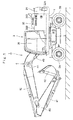
Fig. 1 is a front view showing a wheel type hydraulic excavator according to an embodiment of the present invention. -
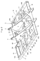
Fig. 2 is a perspective view showing a revolving frame as a single unit. -
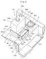
Fig. 3 is a perspective view showing a state where an engine, a heat exchanger, a urea water tank and the like are mounted on the revolving frame. -
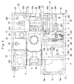
Fig. 4 is a plan view showing a state where the engine, the heat exchanger, the urea water tank and the like are mounted on the revolving frame. -
Fig. 5 is a front view showing the revolving frame and the like, viewed in a direction of arrows V-V inFig. 4 . -
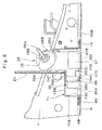
Fig. 6 is an enlarged cross section of an essential part showing a mounting structure of a urea water tank to the revolving frame, viewed in a direction of arrows VI-VI inFig. 4 . -
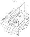
Fig. 7 is an enlarged perspective view of an essential part showing a mounting structure of the urea water tank to the revolving frame from a left oblique rear side. -
Fig. 8 is an enlarged perspective view of an essential part showing a mounting structure of the urea water tank to the revolving frame from a right oblique front side. -
Fig. 9 is an exploded perspective view showing a state where the urea water tank and a tank receiver are exploded. -
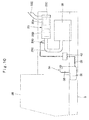
Fig. 10 is a configuration diagram showing the configuration of a NOx purifying device together with an engine and the like. -
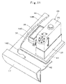
Fig. 11 is a partially enlarged perspective view of an essential part showing a modification in the present invention from a position similar to that ofFig. 7 . - Hereinafter, an embodiment of a construction machine according to the present invention will be in detail explained with reference to
Fig. 1 to Fig. 10 , by taking a wheel type hydraulic excavator provided with a wheel type lower traveling structure as an example. - In
Fig. 1 , a wheel typehydraulic excavator 1 is a representative example of a construction machine according to the present embodiment. The wheel typehydraulic excavator 1 is configured of an automotive wheel typelower traveling structure 2 with left and rightfront wheels 2A and left and rightrear wheels 2B, an upper revolvingstructure 3 that is rotatably mounted on thelower traveling structure 2 thereon and a front device 4 that is tiltably mounted on a front part of the upper revolvingstructure 3. - The front device 4 is provided in a front side of a revolving
frame 5, which will be described later, to be capable of lifting and tilting thereto, thereby performing an excavating operation of earth and sand, and the like. The front device 4 includes aboom 4A that is mounted in a front side portion of left and rightvertical plates frame 5 to be capable of lifting and tilting thereto, anarm 4B that is mounted in a front end part of theboom 4A to be capable of lifting and tilting thereto and abucket 4C that is mounted in a front end part of thearm 4B to be capable of rotating thereto, and further, aboom cylinder 4D, anarm cylinder 4E and abucket cylinder 4F that drive the above components respectively. - In addition, the upper revolving
structure 3 includes the revolvingframe 5, acounterweight 24, anengine 25, aheat exchanger 26, acab 28, a NOx purifyingdevice 33 and aurea water tank 34, which will be described later. - The revolving
frame 5 is configured as a support structure of the upper revolvingstructure 3. As shown inFig. 2 , the revolvingframe 5 includes aflat bottom plate 6, a leftvertical plate 7 and a rightvertical plate 8 that are provided vertically on thebottom plate 6 at an interval in a left-right direction and extend in a front-rear direction, a plurality ofextension beams 9 to 13 and a single cabrear extension beam 14 that extend outside in the left-right direction from thebottom plate 6 and the respectivevertical plates rear part plate 15 and a rightrear part plate 16 that extend outside in the left-right direction from rear part positions from the respectivevertical plates left side frame 17 and aright side frame 18 that are mounted in front ends of therespective extension beams 9 to 14 and the respectiverear part plates bottom plate 6 in the left-right direction. - A
cab front frame 19 is provided in a left front side of the revolvingframe 5 to support a front side of acab 28, and thecab front frame 19 is mounted on thebottom plate 6 to extend from a front end of theleft side frame 17 to the right side (leftvertical plate 7 side). On the other hand, as shown inFig. 4 , thebottom plate 6 includes acenter plate part 6A that is positioned between the respectivevertical plates left plate part 6B that extends in the left side in the left-right direction (hereinafter, simply referred to as "left side") over the leftvertical plate 7, and aright plate part 6C that extends in the right side in the left-right direction (hereinafter, simply referred to as "right side") over the rightvertical plate 8. - Further, the
extension beams rear extension beam 14 that are positioned in the left side among the plurality ofextension beams 9 to 14, and the leftrear part plate 15 are provided in a parallel lining state for connection between theleft plate part 6B of thebottom plate 6, the leftvertical plate 7 and theleft side frame 17. On the other hand, theextension beams 11 to 13 and the rightrear part plate 16 that are positioned in the right side are provided in a parallel lining state for connection between theright plate part 6C of thebottom plate 6, the rightvertical plate 8 and theright side frame 18. - Here, the cab
rear extension beam 14 is disposed in an intermediate part of the front-rear direction to be positioned in the left side of the revolvingframe 5. The cabrear extension beam 14 is positioned in a front side to theheat exchanger 26 which will be described later to support a rear side of thecab 28. As shown inFig. 6 andFig. 8 , the cabrear extension beam 14 is formed with a risingplate part 14A that extends in the left-right direction and rises from theleft plate part 6B of thebottom plate 6, a flat upperhorizontal plate part 14B that is bent form an upper end of the risingplate part 14A and extends to the rear side, and aspace part 14C that is formed between the risingplate part 14A and the upperhorizontal plate part 14B. Therefore, the cabrear extension beam 14 is formed in a reverse L-letter shape as a whole. - As shown in
Fig. 6 , the cabrear extension beam 14 is provided with alower plate part 14D that is positioned between thebottom plate 6 and theleft side frame 17 and extends forward from a lower end of the risingplate part 14A. Mount fixingholes 14E are provided respectively in both sides of the upperhorizontal plate part 14B in the left-right direction. The twomount fixing holes 14E respectively are formed as round holes for mountingvibration isolating mounts 28A that support thecab 28 in a vibration isolating state. - A base end side (right side) of the cab
rear extension beam 14 is jointed to theleft plate part 6B of thebottom plate 6 and a side surface of the leftvertical plate 7 by means of welding and the like, and a front end side (left side) thereof is jointed to an inner side surface of theleft side frame 17 by means of welding and the like. That is, the cabrear extension beam 14 supports the rear side of thecab 28, and is used for connection between thebottom plate 6, the leftvertical plate 7 and theleft side frame 17. - On the other hand, the aforementioned
cab front frame 19 is provided withmount fixing holes 19A that are positioned respectively in both sides of the left-right direction. The twomount fixing holes 19A respectively are provided with thevibration isolating mounts 28A. As shown inFig. 4 , the upperhorizontal plate part 14B of the cabrear extension beam 14 is provided with a notchedportion 14F formed by notching the upperhorizontal plate part 14B between the left and rightmount fixing holes 14E from the rear side. The notchedportion 14F serves for insertion of various hoses and harnesses extending from thecab 28, and the like, and for the weight reduction. - A plurality of
undercovers 20A to 20E are respectively disposed between thebottom plate 6 and the left and right side frames 17, 18 (hereinafter, referring to therespective undercovers 20A to 20E as "undercover 20" as a whole). The undercover 20 is made of a thin-plate shaped steel plate, and is jointed to thebottom plate 6, therespective extension beams 9 to 14, the respective side frames 17, 18 and the like by means of welding, bolts and the like. Theurea water tank 34 which will be described later is mounted on an upper surface of the undercover 20B that is positioned in a lower side to the cabrear extension beam 14 among the respective undercovers 20. - A
front partition plate 21 is provided on an upper surface of the upperhorizontal plate part 14B in the cabrear extension beam 14. Thefront partition plate 21 is formed as a plate-shaped member that rises from the upperhorizontal plate part 14B along a rear surface of thecab 28 and extends in the left-right direction. A front end of anupper surface cover 32B of anexterior cover 32 which will be described later is supported on an upper end of thefront partition plate 21. - A
rear partition plate 22 is disposed to face thefront partition plate 21. Therear partition plate 22 is formed as a plate-shaped member that rises from the leftrear part plate 15 among the left and rightrear part plates upper surface cover 32B of theexterior cover 32 is similarly supported on an upper end of therear partition plate 22. - Further, a
utility room 23 is provided between thefront partition plate 21 and therear partition plate 22. Theutility room 23 is disposed outward of the revolvingframe 5 in the left-right direction, that is, in asuction surface 26A side of theheat exchanger 26 which will be described later. Anair cleaner 31 and aurea water tank 34, which will be described later, and the like are disposed in theutility room 23. - A
counterweight 24 is provided in a rear part of the revolvingframe 5. Thecounterweight 24 is mounted on rear end parts of the left and rightvertical plates frame 5, and acts as a weight balance to the front device 4. - An
engine 25 is provided on the revolvingframe 5 to be positioned in a front side to thecounterweight 24. As shown inFig. 4 , theengine 25 is mounted on the revolvingframe 5 in a horizontal state of extending in the left-right direction. A coolingfan 25A is disposed in a left side to theengine 25. Theengine 25 is configured, for example, as a diesel engine and serves as a drive source for rotating and driving ahydraulic pump 27 which will be described later. Further, theengine 25 is provided with anintake pipe 25B for sucking air and anexhaust pipe 25C for discharging an exhaust gas. Anair cleaner 31 which will be described later is connected to theintake pipe 25B, and aNOx purifying device 33 which will be described later is connected to theexhaust pipe 25C. - The
heat exchanger 26 is disposed at the left side in the length direction to theengine 25, that is, in theutility room 23 side. Theheat exchanger 26 accommodates a radiator for cooling engine-cooling water, an oil cooler for cooling operating oil, an intercooler for cooling air to be aspired into theengine 25 and the like inside a frame-shaped member. Here, theheat exchanger 26 sucks outside air as cooling wind from the outside (left side) in the left-right direction, and is provided with asuction surface 26A as a surface at the opposite to the coolingfan 25A. The suction surface 26A forms a part of a closing surface for closing the right side of theutility room 23. - A
hydraulic pump 27 is mounted in the right side to theengine 25. Thehydraulic pump 27 is rotated and driven by theengine 25 to deliver the operating oil as pressurized oil. Thehydraulic pump 27 is formed of, for example, a radial piston hydraulic pump of a swash plate type or a bent axis type and the like. - The
cab 28 is mounted on the revolvingframe 5 to be positioned in the front side to theheat exchanger 26. Thecab 28 in which an operator gets accommodates therein the operator's seat on which the operator sits, a traveling operating lever, a working operating lever, and the like (none is shown). Thecab 28 has a front side that is supported by thecab front frame 19 of the revolvingframe 5 and a rear side that is supported by the cabrear extension beam 14. In this case, thecab 28 is supported at four corners thereof by the fourvibration isolating mounts 28A (only one is shown inFig. 8 ) inserted in the respectivemount fixing holes 19A of thecab front frame 19 and themount fixing holes 14E of the cabrear extension beam 14 respectively. - A
hydraulic oil tank 29 is provided in the right side of the revolvingframe 5 to be positioned forward of thehydraulic pump 27. Thehydraulic oil tank 29 reserves operating oil to be supplied to thehydraulic pump 27. In addition, afuel tank 30 is provided to be adjacent to the front side of thehydraulic oil tank 29. Thefuel tank 30 reserves fuel to be supplied to theengine 25. - The
air cleaner 31 is disposed in theutility room 23 to be positioned upstream of theheat exchanger 26. Theair cleaner 31 separates dusts in the aspired air by centrifugation, and circulates only the cleansed air into theengine 25 side. - The
exterior cover 32 is provided on the revolvingframe 5 to be positioned between thecab 28 and thecounterweight 24. Theengine 25, theheat exchanger 26, thehydraulic pump 27, theNOx purifying device 33 and the like are accommodated in theexterior cover 32. Theexterior cover 32 includes aleft surface cover 32A that is provided to extend upward on theleft side frame 17 to face theheat exchanger 26, a right surface cover (not shown) that is provided to extend upward on theright side frame 18 to face thehydraulic pump 27, anupper surface cover 32B that extends in the left-right direction across an upper part of each of the side surface covers 32A and anengine cover 32C mounted on theupper surface cover 32B to be capable of opening/closing. Here, theleft surface cover 32A covers the left side of theutility room 23 to be capable of opening/closing, and can cause theurea water tank 34 to be exposed to outside in the opened state. - Next, an explanation will be made of the configuration of the
NOx purifying device 33 that is provided to be connected to an exhaust side of theengine 25 for treating an exhaust gas emitted from theengine 25. - The
NOx purifying device 33 is disposed in the right upper side to theengine 25. TheNOx purifying device 33 is provided in theexhaust pipe 25C of theengine 25. As shown inFig. 10 , theNOx purifying device 33 includes acylindrical case 33A that is formed as a cylindrical vessel extending in the front-rear direction, a ureaselective reduction catalyst 33B that is provided in the upstream side in thecylindrical case 33A, anoxidation catalyst 33C that is disposed in thecylindrical case 33A to be positioned downstream of the ureaselective reduction catalyst 33B and a ureawater injection valve 33D that is provided in theexhaust pipe 25C of theengine 25 upstream of the ureaselective reduction catalyst 33B. Atail pipe 33E is provided to project upward on the rear side in thecylindrical case 33A. - The
NOx purifying device 33 thus configured ejects urea water supplied from theurea water tank 34 which will be described later into the exhaust gas from the ureawater injection valve 33D. As a result, the ureaselective reduction catalyst 33B uses ammonia generated from the urea water to cause reduction reaction of NOx (nitrogen oxides) in the exhaust gas, which is decomposed into water and nitrogen. Then, carbon oxides (CO), hydrocarbon (HC) and the like in the exhaust gas become oxidized by theoxidation catalyst 33C for removal. - Next, an explanation will be made of the configuration and mounting structure of the
urea water tank 34 that is a characteristic part in the present invention. - The
urea water tank 34 is provided on the revolvingframe 5 to be positioned in a rear side to thecab 28. Theurea water tank 34 reserves urea water to be supplied to the ureawater injection valve 33D in theNOx purifying device 33. Theurea water tank 34 is formed of avertical tank part 35 that is positioned in the rear side and extends in the upper-lower direction, and alateral tank part 36 that extends from a lower part of thevertical tank part 35 to the front side. As a result, theurea water tank 34 is formed in an L-letter shape as a whole. - The
vertical tank part 35 in theurea water tank 34 is formed in a cuboid shape extending in the upper-lower direction. That is, as shownFig. 7 to Fig. 9 , thevertical tank part 35 is formed of, for example, afront surface plate 35A, arear surface plate 35B, aleft surface plate 35C, aright surface plate 35D, anupper surface plate 35E and alower surface plate 35F. Awater supply port 35G for supplying urea water is provided in an upper part position of thevertical tank part 35, that is, in a boundary position between theleft surface plate 35C and theupper surface plate 35E to be inclined outside in the left-right direction. Thevertical tank part 35 thus formed is disposed at the front side position in theutility room 23, specifically near thefront partition plate 21. - The
lateral tank part 36 is formed in a cuboid shape laterally (horizontal direction) extending from a lower part of thefront surface plate 35A in thevertical tank part 35 to the front side. That is, thelateral tank part 36 is formed of, for example, afront surface plate 36A, aleft surface plate 36B, aright surface plate 36C, anupper surface plate 36D and alower surface plate 36E. Theupper surface plate 36D is provided with a recessed groove-shapedbelt mounting groove 36F extending in the left-right direction. - Here, as shown in
Fig. 8 , thelateral tank part 36 is disposed in a position closer to the right side (leftvertical plate 7 side) relative to thevertical tank part 35. Therefore, even in a case where thevertical tank part 35 is disposed near theleft side frame 17, thelateral tank part 36 can be disposed in a position of avoiding each of themount fixing holes 14E in a plan view, that is, each of thevibration isolating mounts 28A. As a result, theurea water tank 34 can be disposed in an outside position (near the left side frame 17) where the water supply work and the maintenance work are easily performed without interference with each of thevibration isolating mounts 28A. - A
tank receiver 37 is provided in a bottom part side of theurea water tank 34. As shown inFig. 9 , thetank receiver 37 is formed of an L-letter shapedbottom part 37A a left front side of which is notched, and aframe part 37B rising from the periphery of thebottom part 37A. Theframe part 37B is provided withbrackets 37C in a position of interposing thelateral tank part 36 in the left-right direction therebetween. - Next, description will be made of an example of the procedure of mounting the
urea water tank 34 thus configured on the undercover 20B. Theurea water tank 34 accommodated in thetank receiver 37 is disposed in theutility room 23. In this case, thespace part 14C provided in the cabrear extension beam 14 is used to accommodate thelateral tank part 36 in thespace part 14C. In this state, a fixingbelt 38 as a fixing tool is engaged to thebelt mounting groove 36F of thelateral tank part 36, andbolts 38A are used to fix both ends of the fixingbelt 38 together with thebracket 37C of thetank receiver 37 on the undercover 20B. As a result, theurea water tank 34 can be mounted integrally on the undercover 20B in a state of being positioned along a rear surface of thecab 28. - Here, as shown in
Fig. 10 , theurea water tank 34 is connected to the ureawater injection valve 33D in theNOx purifying device 33 via a ureawater supply pipe 39 and asupply pump 40. - In addition, the
urea water tank 34 can be disposed in the outside position in the left-right direction within easy reach from the surroundings even in theutility room 23. Therefore, by opening theleft surface cover 32A of theexterior cover 32, a refilling work of urea water and a maintenance work such as inspections and repair and the like can be easily performed. - The wheel type
hydraulic excavator 1 as the construction machine according to the present embodiment has the aforementioned configuration. Next, an explanation will be made of an operation of the wheel typehydraulic excavator 1. - An onboard operator in the
cab 28 starts theengine 25 to drive thehydraulic pump 27. As a result, the front device 4 is driven in response to an operation of the operating lever (not shown) by the operator, thus making it possible to perform an excavating operation of earth and sand, and the like. - In addition, nitrogen oxides (NOx) as harmful substances are discharged from the
exhaust pipe 25C at the operating of theengine 25. At this time, thesupply pump 40 is used to deliver urea water in theurea water tank 34 to the ureawater injection valve 33D in theNOx purifying device 33 from the ureawater supply pipe 39. Thereby, theNOx purifying device 33 ejects urea water into the exhaust gas from the ureawater injection valve 33D to generate ammonia. As a result, in the ureaselective reduction catalyst 33B, the nitrogen oxide is reduced to water and nitrogen, which are discharged to outside via theoxidation catalyst 33C and thetail pipe 33E, thus making it possible to reduce an exhaust amount of the nitrogen oxides. - Thus, according to the present embodiment, since the
urea water tank 34 is formed in an L-letter shaped vessel with thevertical tank part 35 and thelateral tank part 36, the volume of theurea water tank 34 can be increased by a size of thelateral tank part 36. In this case, using thespace part 14C of the cabrear extension beam 14 formed in a reverse L-letter shape by the risingplate part 14A and the upperhorizontal plate part 14B, thelateral tank part 36 of the L-letter shapedurea water tank 34 can be disposed in thespace part 14C. As a result, even in case where a space for installing theurea water tank 34 is small, the volume of theurea water tank 34 can be increased using thespace part 14C as a dead space. - Since the
urea water tank 34 can suppress an occupation space in theutility room 23 to be small by using the dead space, degrees of freedom in the arrangement location can be increased. Thereby, theurea water tank 34 can be disposed in the outside position in the left-right direction within easy reach from outside, improving workability of a water supply work of urea water, a maintenance work of the urea water tank and the like. - Since the
utility room 23 is disposed in thesuction surface 26A side from which theheat exchanger 26 sucks outside air, that is, in the outside position in the left-right direction, an operator can easily reach thevertical tank part 35 in theurea water tank 34 disposed in theutility room 23, from outside. Therefore, the workability of a water supply work to theurea water tank 34, a maintenance work of theurea water tank 34 and the like can be improved. - The
lateral tank part 36 in theurea water tank 34 is disposed in a position closer to the right side relative to thevertical tank part 35. Therefore, thelateral tank part 36 can be disposed in a position of avoiding the twomount fixing holes 14E formed on the upperhorizontal plate part 14B of the cabrear extension beam 14, that is, each of thevibration isolating mounts 28A. As a result, theurea water tank 34 can be disposed in a position without interference with each of thevibration isolating mounts 28A disposed in the rear side to thecab 28. - The
urea water tank 34 uses the fixingbelt 38 as a fixing tool to be fixed on the undercover 20B between thebottom plate 6 and theleft side frame 17 using thebolts 38A. Therefore, theurea water tank 34 can be provided on the undercover 20B of the revolvingframe 5 to be easily removed from. - Further, the
water supply port 35G of urea water is provided on the upper part position of thevertical tank part 35 in theurea water tank 34. Thereby, in a case of refilling urea water in theurea water tank 34, the water supply work can be easily performed only by opening theleft surface cover 32A of theexterior cover 32. - It should be noted that the present embodiment exemplifies a case where the
urea water tank 34 is mounted on the undercover 20B disposed under the cabrear extension beam 14 of the revolvingframe 5. However, the present invention is not limited thereto, and, for example, may be configured as a modification shown inFig. 11 . That is, in the modification shown inFig. 11 , abottom plate 41 extends to a position near theleft side frame 17, and theurea water tank 34 is mounted on thebottom plate 41. In this case, an undercover 42 is formed to be narrow in width to adjust to thebottom plate 41. - The present embodiment exemplifies a case where the
urea water tank 34 is bolted on the undercover 20B using the fixingbelt 38 as the fixing tool. However, the present invention is not limited thereto, and for example, it may be configured that theurea water tank 34 is directly bolted on the undercover 20B. - In the present embodiment, the
lateral tank part 36 in theurea water tank 34 is disposed in a position closer to the right side relative to thevertical tank part 35. However, the present invention is not limited thereto, and, for example, thelateral tank part 36 may be formed to have a width dimension identical to that of thevertical tank part 35. Besides, as long as theurea water tank 34 is shaped to be accommodated in the dead space (space part 14C) in theutility room 23, the shape of theurea water tank 34 is not limited. - The present embodiment exemplifies a case where the
urea water tank 34 is accommodated in thetank receiver 37. However, the present invention is not limited thereto, and, for example, it may be configured that theurea water tank 34 is directly mounted on the undercover 20B with thetank receiver 37 being eliminated. - In the present embodiment, the front and
rear partition plates horizontal plate part 14B of the cabrear extension beam 14 and in the rear end position of theleft side frame 17 of the revolvingframe 5 respectively. However, the present invention is not limited thereto, and may be configured to, for example, provide another partition plate between theurea water tank 34 and theheat exchanger 26. - The aforementioned embodiment exemplifies a case where the
urea water tank 34 is provided in the wheel typehydraulic excavator 1. However, the present invention is not limited thereto, and may be applied to, for example, a crawler type hydraulic excavator. Further, the present invention is not limited to the hydraulic excavator, and may be applied to a hydraulic crane. -
- 1: Wheel type hydraulic excavator (Construction machine)
- 2: Lower traveling structure
- 3: Upper revolving structure
- 4: Front device
- 5: Revolving frame
- 6, 41: Bottom plate
- 7: Left vertical plate
- 8: Right vertical plate
- 9 to 13: Extension beam
- 14: Cab rear extension beam
- 14A: Rising plate part
- 14B: Upper horizontal plate part
- 14C: Space part
- 14E: Mount fixing hole
- 15: Left rear part plate
- 16: Right rear part plate
- 17: Left side frame
- 18: Right side frame
- 20A to 20E, 42: Undercover
- 21: Front partition plate
- 22: Rear partition plate
- 23: Utility room
- 24: Counterweight
- 25: Engine
- 25C: Exhaust pipe
- 26: Heat exchanger
- 26A: Suction surface
- 28: Cab
- 28A: Vibration isolating mount
- 33: NOx purifying device
- 33B: Urea selective reduction catalyst
- 33D: Urea water injection valve
- 34: Urea water tank
- 35: Vertical tank part
- 35G: Water supply port
- 36: Lateral tank part
- 38: Fixing belt (Fixing tool)
Claims (4)
- A construction machine comprising:an automotive lower traveling structure (2);an upper revolving structure (3) that is rotatably mounted on said lower traveling structure (2); anda front device (4) that is liftably mounted in a front part of said upper revolving structure (3), whereinsaid upper revolving structure (3) includes a revolving frame (5) that is configured as a support structure, a counterweight (24) that is positioned in a rear side to said revolving frame (5) to act as a weight balance to said front device (4), an engine (25) that is disposed on said revolving frame (5) in a laterally-facing state to be positioned in a front side to said counterweight (24), a heat exchanger (26) that is provided to be positioned in one side of said engine (25) in a length direction, a cab (28) that is provided on said revolving frame (5) to be positioned in a front side to said heat exchanger (26), a NOx purifying device (33) that is mounted in an exhaust pipe (25C) of said engine (25) and is provided with a urea selective reduction catalyst (33B) for removing nitrogen oxides in an exhaust gas by injection of urea water from a urea water injection valve (33D), and a urea water tank (34) that reserves urea water therein for supply to said urea water injection valve (33D) in said NOx purifying device (33), whereinsaid revolving frame (5) includes a flat bottom plate (6, 41), left and right vertical plates (7, 8) that are provided vertically on said bottom plate (6, 41) at an interval in a left-right direction to extend in a front-rear direction, a plurality of extension beams (9 to 14) that extend in the left-right direction from said bottom plate (6, 41) and said respective vertical plates (7, 8), and a left side frame (17) and a right side frame (18) that are mounted in front ends of said respective extension beams (9 to 14) to extend in the front-rear direction in outside positions of said bottom plate (6, 41) in the left-right direction, characterized in that:a cab rear extension beam (14) that is positioned in a front side to said heat exchanger (26) to support a rear side of said cab (28) among the plurality of said extension beams (9 to 14), is formed in a reverse L-letter shape with a rising plate part (14A) that rises from said bottom plate (6, 41), an upper horizontal plate part (14B) that is bent from an upper end of said rising plate part (14A) and extends to the rear side, and a space part (14C) that is formed between said rising plate part (14A) and said upper horizontal plate part (14B);said urea water tank (34) is formed in an L-letter shaped vessel with a vertical tank part (35) that extends in the upper-lower direction and a lateral tank part (36) that extends from a lower part of said vertical tank part (35) to the front side; said lateral tank part (36) in said urea water tank (34) is disposed in said space part (14C) formed in said cab rear extension beam (14),said vertical tank part (35) in said urea water tank (34) extends upward along a rear surface of said cab (28), anda water supply port (35G) of urea water is provided on an upper part position of said vertical tank part (35).
- The construction machine according to claim 1, wherein
a front partition plate (21) is provided on an upper surface of said upper horizontal plate part (14B) of said cab rear extension beam (14) to rise from said upper horizontal plate part (14B) and extend in the left-right direction,
left and right rear part plates (15, 16) are provided between said left and right vertical plates (7, 8) and said left and right side frames (17, 18) respectively to extend in parallel to said extension beam (10, 13),
a rear partition plate (22) that extends in the left-right direction is provided in said left rear part plate (15) of said left and right rear part plates (15, 16) to face said front partition plate (21),
a utility room (23) is provided between said front partition plate (21) and said rear partition plate (22) to be positioned in a suction surface (26A) side where said heat exchanger (26) sucks outside air, and
said vertical tank part (35) in said urea water tank (34) is disposed in a front side position of said utility room (23). - The construction machine according to claim 1, wherein
said upper horizontal plate part (14B) in said cab rear extension beam (14) is provided with mount fixing holes (14E) positioned respectively in both sides of in the left-right direction to mount vibration isolating mounts (28A) that support said cab (28) in a vibration isolating state, and
said lateral tank part (36) in said urea water tank (34) is disposed in a position of avoiding each of said mount fixing holes (14E) in a plan view. - The construction machine according to claim 1, wherein
an undercover (20B) is provided in a lower side to said cab rear extension beam (14) to be positioned between said bottom plate (6) and said left side frame (17), and
said urea water tank (34) is mounted on said undercover (20B) using a fixing tool (38).
Applications Claiming Priority (1)
| Application Number | Priority Date | Filing Date | Title |
|---|---|---|---|
| JP2014087991A JP6297905B2 (en) | 2014-04-22 | 2014-04-22 | Construction machinery |
Publications (3)
| Publication Number | Publication Date |
|---|---|
| EP2937468A2 EP2937468A2 (en) | 2015-10-28 |
| EP2937468A3 EP2937468A3 (en) | 2015-11-04 |
| EP2937468B1 true EP2937468B1 (en) | 2016-11-23 |
Family
ID=53039232
Family Applications (1)
| Application Number | Title | Priority Date | Filing Date |
|---|---|---|---|
| EP15164714.6A Active EP2937468B1 (en) | 2014-04-22 | 2015-04-22 | Exhaust gas treatment unit for a construction machine |
Country Status (3)
| Country | Link |
|---|---|
| US (1) | US9453327B2 (en) |
| EP (1) | EP2937468B1 (en) |
| JP (1) | JP6297905B2 (en) |
Families Citing this family (17)
| Publication number | Priority date | Publication date | Assignee | Title |
|---|---|---|---|---|
| FR2995831B1 (en) * | 2012-09-25 | 2014-08-29 | Renault Sa | IMPLANTATION OF UREA RESERVOIR PIPE IN A DIESEL ENGINE UTILITY VEHICLE AND CORRESPONDING VEHICLE |
| WO2015053273A1 (en) * | 2013-10-08 | 2015-04-16 | 住友建機株式会社 | Shovel |
| JP5719092B1 (en) * | 2014-08-25 | 2015-05-13 | 株式会社小松製作所 | Bulldozer |
| US9945099B2 (en) * | 2014-11-21 | 2018-04-17 | Kcm Corporation | Industrial vehicle |
| JP6307019B2 (en) * | 2014-11-28 | 2018-04-04 | 日立建機株式会社 | Construction machinery |
| JP5918444B1 (en) * | 2015-01-07 | 2016-05-18 | 株式会社小松製作所 | Self-propelled recycling machine |
| KR101698288B1 (en) * | 2015-05-21 | 2017-01-19 | 가부시키가이샤 고마쓰 세이사쿠쇼 | Hydraulic excavator |
| US20170107689A1 (en) * | 2015-10-14 | 2017-04-20 | Caterpillar Inc. | Support structure for frame of a machine |
| KR20170066275A (en) | 2015-12-04 | 2017-06-14 | 가부시키가이샤 고마쓰 세이사쿠쇼 | Work vehicle |
| JP6693117B2 (en) * | 2015-12-18 | 2020-05-13 | 三菱自動車工業株式会社 | Arrangement structure of urea water tank |
| JP6445476B2 (en) * | 2016-01-29 | 2018-12-26 | 日立建機株式会社 | Construction machinery |
| US10377423B2 (en) * | 2017-08-16 | 2019-08-13 | Cnh Industrial America Llc | Multiple system support arrangement for engine compartment |
| JP7128032B2 (en) * | 2018-06-04 | 2022-08-30 | キャタピラー エス エー アール エル | construction machine frame |
| CN109017279B (en) * | 2018-09-30 | 2024-04-02 | 安徽安凯汽车股份有限公司 | Rear-mounted passenger train urea jar fixed knot constructs |
| JP7166202B2 (en) * | 2019-02-28 | 2022-11-07 | 日立建機株式会社 | construction machinery |
| CN110159399B (en) * | 2019-04-30 | 2020-08-11 | 中国石油天然气股份有限公司 | Noise-eliminating and smoke-eliminating device for special vehicle |
| CN113653122B (en) * | 2021-09-26 | 2023-04-28 | 徐工集团工程机械股份有限公司科技分公司 | Tail sinking type rear frame structure with water tank tail gas treatment and arranged at side of cab |
Family Cites Families (62)
| Publication number | Priority date | Publication date | Assignee | Title |
|---|---|---|---|---|
| JP2003082705A (en) * | 2001-09-10 | 2003-03-19 | Hitachi Constr Mach Co Ltd | Turning frame of construction machine and its of manufacturing method |
| JP2005030067A (en) * | 2003-07-14 | 2005-02-03 | Shin Caterpillar Mitsubishi Ltd | Swing frame for construction machinery, engine-room structure of construction machinery and cooling device for construction machinery |
| JP4387893B2 (en) * | 2004-08-18 | 2009-12-24 | 日立建機株式会社 | Construction machinery cab |
| JP4343900B2 (en) * | 2005-12-26 | 2009-10-14 | 日立建機株式会社 | Construction machinery |
| KR100753991B1 (en) * | 2006-09-22 | 2007-08-31 | 볼보 컨스트럭션 이키프먼트 홀딩 스웨덴 에이비 | Upper frame structure of supporting cab of construction machine |
| JP2008231999A (en) * | 2007-03-20 | 2008-10-02 | Komatsu Ltd | Construction vehicle |
| JP4966100B2 (en) * | 2007-05-31 | 2012-07-04 | 日立建機株式会社 | Construction machinery |
| US8186156B2 (en) * | 2007-06-26 | 2012-05-29 | Hitachi Construction Machinery Co., Ltd. | Automotive construction machine |
| JP4900163B2 (en) * | 2007-09-26 | 2012-03-21 | コベルコ建機株式会社 | Construction machinery |
| US8056671B2 (en) * | 2007-10-12 | 2011-11-15 | Mazda Motor Corporation | Exhaust-gas purification device disposition structure of vehicle |
| JP4928474B2 (en) * | 2008-01-08 | 2012-05-09 | 日立建機株式会社 | Arrangement structure of NOx reduction device for construction machinery |
| JP5101324B2 (en) * | 2008-02-07 | 2012-12-19 | 日立建機株式会社 | Arrangement structure of NOx reduction device for construction machinery |
| JP2011012509A (en) * | 2009-07-06 | 2011-01-20 | Hitachi Constr Mach Co Ltd | Construction machine |
| JP2011011725A (en) * | 2009-07-06 | 2011-01-20 | Sumitomo (Shi) Construction Machinery Co Ltd | Construction machine |
| FR2959497B1 (en) * | 2010-05-03 | 2014-01-10 | Coutier Moulage Gen Ind | FLUID TANK WITH HEATED RESERVE BOWL |
| JP2011247232A (en) * | 2010-05-31 | 2011-12-08 | Caterpillar Sarl | Working machine |
| WO2012026233A1 (en) * | 2010-08-26 | 2012-03-01 | 日立建機株式会社 | Construction machine |
| JP5356341B2 (en) * | 2010-09-16 | 2013-12-04 | 日立建機株式会社 | Construction machinery |
| JP5649463B2 (en) * | 2011-01-14 | 2015-01-07 | 日立建機株式会社 | Construction machinery |
| JP2012171596A (en) * | 2011-02-24 | 2012-09-10 | Hitachi Constr Mach Co Ltd | Construction machine |
| JP5615763B2 (en) * | 2011-06-14 | 2014-10-29 | 日立建機株式会社 | Construction machinery |
| US20130000281A1 (en) * | 2011-06-30 | 2013-01-03 | Caterpillar Inc. | Def pump mounted to tank |
| JP5780047B2 (en) * | 2011-08-10 | 2015-09-16 | コベルコ建機株式会社 | Construction machinery piping structure |
| JP5608137B2 (en) * | 2011-08-16 | 2014-10-15 | 日立建機株式会社 | Exhaust gas purification device |
| JP5865040B2 (en) * | 2011-11-30 | 2016-02-17 | 株式会社クボタ | Work vehicle |
| US20130145749A1 (en) * | 2011-12-12 | 2013-06-13 | Caterpillar Inc. | Fluid manifold for use in an scr dosing system |
| JP2013147893A (en) * | 2012-01-23 | 2013-08-01 | Hitachi Constr Mach Co Ltd | Work machine and arrangement structure for selector valve thereof |
| JP5939570B2 (en) * | 2012-05-22 | 2016-06-22 | キャタピラー エス エー アール エル | Airframe and work machine |
| KR20140091566A (en) * | 2012-07-05 | 2014-07-21 | 가부시키가이샤 고마쓰 세이사쿠쇼 | Engine unit and working vehicle |
| JP5859933B2 (en) * | 2012-08-31 | 2016-02-16 | 日立建機株式会社 | Construction machinery |
| FR2995831B1 (en) * | 2012-09-25 | 2014-08-29 | Renault Sa | IMPLANTATION OF UREA RESERVOIR PIPE IN A DIESEL ENGINE UTILITY VEHICLE AND CORRESPONDING VEHICLE |
| WO2014064956A1 (en) * | 2012-10-26 | 2014-05-01 | 株式会社小松製作所 | Wheel loader |
| EP2743472B1 (en) * | 2012-10-26 | 2017-03-01 | Komatsu Ltd. | Work vehicle |
| US9353502B2 (en) * | 2012-10-26 | 2016-05-31 | Komatsu Ltd. | Wheel loader |
| US8985262B2 (en) * | 2012-10-30 | 2015-03-24 | Komatsu Ltd. | Construction vehicle equipped with exhaust aftertreatment device |
| CN104024016B (en) * | 2012-10-30 | 2016-08-31 | 株式会社小松制作所 | It is equipped with the construction vehicle of exhaust gas post-treatment device |
| JP5975859B2 (en) * | 2012-11-29 | 2016-08-23 | ヤンマー株式会社 | Engine equipment |
| JP5336646B1 (en) * | 2012-12-20 | 2013-11-06 | 株式会社小松製作所 | Work vehicle |
| US9061582B2 (en) * | 2013-02-15 | 2015-06-23 | Komatsu Ltd. | Hydraulic excavator |
| WO2014141408A1 (en) * | 2013-03-13 | 2014-09-18 | 株式会社小松製作所 | Working vehicle |
| JP6343119B2 (en) * | 2013-03-15 | 2018-06-13 | ヤンマー株式会社 | Combine engine equipment |
| US9683348B2 (en) * | 2013-03-15 | 2017-06-20 | Yanmar Co., Ltd. | Engine device |
| JP6066787B2 (en) * | 2013-03-15 | 2017-01-25 | ヤンマー株式会社 | Combine engine equipment |
| JP5956373B2 (en) * | 2013-03-28 | 2016-07-27 | ヤンマー株式会社 | Engine device for work vehicle |
| KR20200019781A (en) * | 2013-03-28 | 2020-02-24 | 얀마 가부시키가이샤 | Engine device |
| CN105143630B (en) * | 2013-04-26 | 2017-11-24 | 洋马株式会社 | Tractor |
| CN105209281B (en) * | 2013-06-05 | 2017-11-03 | 日立建机株式会社 | Engineering machinery |
| JP6190182B2 (en) * | 2013-06-28 | 2017-08-30 | 株式会社タダノ | Exhaust purification system for rough terrain cranes |
| CN104520514B (en) * | 2013-08-08 | 2016-07-06 | 株式会社小松制作所 | Wheel loader |
| CN104619541B (en) * | 2013-08-09 | 2016-02-10 | 株式会社小松制作所 | Supporting mechanism, exhaust treatment unit, wheel type loader |
| US9238901B2 (en) * | 2013-08-09 | 2016-01-19 | Komatsu Ltd. | Supporting mechanism, exhaust treatment unit, and wheel loader |
| KR101509950B1 (en) * | 2013-10-24 | 2015-04-07 | 현대자동차주식회사 | Urea apparatus for vehicle |
| KR101518938B1 (en) * | 2013-12-17 | 2015-05-11 | 현대자동차 주식회사 | Urea solution venting system for vehicle |
| DE112013000260B4 (en) * | 2013-12-27 | 2016-10-20 | Komatsu Ltd. | working vehicle |
| DE112014000013B4 (en) * | 2014-01-08 | 2018-08-09 | Komatsu Ltd. | Reductant tank and work vehicle |
| DE112014000021B4 (en) * | 2014-02-26 | 2017-11-09 | Komatsu Ltd. | Construction Vehicle |
| JP5940107B2 (en) * | 2014-03-17 | 2016-06-29 | 日立建機株式会社 | Urea water supply system for construction machinery |
| EP2842783B1 (en) * | 2014-03-31 | 2016-10-12 | Komatsu Ltd. | Work vehicle |
| WO2014181612A1 (en) * | 2014-03-31 | 2014-11-13 | 株式会社小松製作所 | Utility vehicle |
| JP5607279B1 (en) * | 2014-03-31 | 2014-10-15 | 株式会社小松製作所 | Work vehicle |
| DE102014209130A1 (en) * | 2014-05-14 | 2015-11-19 | Engineering Center Steyr Gmbh & Co. Kg | Chassis for commercial vehicles |
| JP6218674B2 (en) * | 2014-05-28 | 2017-10-25 | 株式会社クボタ | Work vehicle |
-
2014
- 2014-04-22 JP JP2014087991A patent/JP6297905B2/en active Active
-
2015
- 2015-04-21 US US14/691,632 patent/US9453327B2/en active Active
- 2015-04-22 EP EP15164714.6A patent/EP2937468B1/en active Active
Non-Patent Citations (1)
| Title |
|---|
| None * |
Also Published As
| Publication number | Publication date |
|---|---|
| EP2937468A3 (en) | 2015-11-04 |
| US20150299983A1 (en) | 2015-10-22 |
| EP2937468A2 (en) | 2015-10-28 |
| JP6297905B2 (en) | 2018-03-20 |
| JP2015206223A (en) | 2015-11-19 |
| US9453327B2 (en) | 2016-09-27 |
Similar Documents
| Publication | Publication Date | Title |
|---|---|---|
| EP2937468B1 (en) | Exhaust gas treatment unit for a construction machine | |
| US9010095B2 (en) | Exhaust treatment unit and method of attaching and detaching exhaust treatment unit | |
| EP2248695B1 (en) | Construction machine | |
| US20130319787A1 (en) | Construction machine | |
| JP4705130B2 (en) | Construction machinery | |
| KR101628798B1 (en) | Reducing agent tank and work vehicle | |
| EP3009759B1 (en) | Utility vehicle | |
| US8857557B2 (en) | Work vehicle | |
| WO2014192405A1 (en) | Work vehicle | |
| WO2015045022A1 (en) | Work vehicle | |
| KR101554919B1 (en) | Exhaust treatment unit | |
| CN103890340A (en) | Exhaust treatment unit | |
| KR101495588B1 (en) | Exhaust treatment unit | |
| US10060094B2 (en) | Arrangement structure for a reducing agent tank for a construction machine | |
| US20180245310A1 (en) | Construction Machine | |
| JP5468393B2 (en) | Construction machinery | |
| EP3029207B1 (en) | Construction machine | |
| JP2015101881A (en) | Construction machine | |
| US10174482B2 (en) | Construction machine | |
| JP6632920B2 (en) | Construction machinery | |
| JP7459714B2 (en) | Frame for supporting the drive device of construction machinery and the exhaust gas treatment device of construction machinery | |
| KR101578337B1 (en) | Hydraulic shovel | |
| JP2022186168A (en) | Work machine | |
| JP2005336769A (en) | Construction machinery |
Legal Events
| Date | Code | Title | Description |
|---|---|---|---|
| PUAL | Search report despatched |
Free format text: ORIGINAL CODE: 0009013 |
|
| PUAI | Public reference made under article 153(3) epc to a published international application that has entered the european phase |
Free format text: ORIGINAL CODE: 0009012 |
|
| 17P | Request for examination filed |
Effective date: 20150825 |
|
| AK | Designated contracting states |
Kind code of ref document: A2 Designated state(s): AL AT BE BG CH CY CZ DE DK EE ES FI FR GB GR HR HU IE IS IT LI LT LU LV MC MK MT NL NO PL PT RO RS SE SI SK SM TR |
|
| AX | Request for extension of the european patent |
Extension state: BA ME |
|
| AK | Designated contracting states |
Kind code of ref document: A3 Designated state(s): AL AT BE BG CH CY CZ DE DK EE ES FI FR GB GR HR HU IE IS IT LI LT LU LV MC MK MT NL NO PL PT RO RS SE SI SK SM TR |
|
| AX | Request for extension of the european patent |
Extension state: BA ME |
|
| RIC1 | Information provided on ipc code assigned before grant |
Ipc: E02F 9/08 20060101AFI20150928BHEP Ipc: B66C 13/00 20060101ALI20150928BHEP Ipc: B60K 13/04 20060101ALI20150928BHEP Ipc: F01N 13/00 20100101ALI20150928BHEP Ipc: F01N 3/20 20060101ALI20150928BHEP Ipc: E02F 9/16 20060101ALI20150928BHEP |
|
| GRAP | Despatch of communication of intention to grant a patent |
Free format text: ORIGINAL CODE: EPIDOSNIGR1 |
|
| RIC1 | Information provided on ipc code assigned before grant |
Ipc: E02F 9/08 20060101AFI20160721BHEP Ipc: E02F 9/16 20060101ALI20160721BHEP Ipc: B62D 33/06 20060101ALI20160721BHEP Ipc: B66C 13/00 20060101ALI20160721BHEP Ipc: F01N 13/00 20100101ALI20160721BHEP Ipc: B60K 13/04 20060101ALI20160721BHEP Ipc: F01N 3/20 20060101ALI20160721BHEP |
|
| INTG | Intention to grant announced |
Effective date: 20160812 |
|
| GRAS | Grant fee paid |
Free format text: ORIGINAL CODE: EPIDOSNIGR3 |
|
| GRAA | (expected) grant |
Free format text: ORIGINAL CODE: 0009210 |
|
| AK | Designated contracting states |
Kind code of ref document: B1 Designated state(s): AL AT BE BG CH CY CZ DE DK EE ES FI FR GB GR HR HU IE IS IT LI LT LU LV MC MK MT NL NO PL PT RO RS SE SI SK SM TR |
|
| REG | Reference to a national code |
Ref country code: GB Ref legal event code: FG4D |
|
| REG | Reference to a national code |
Ref country code: CH Ref legal event code: EP |
|
| REG | Reference to a national code |
Ref country code: IE Ref legal event code: FG4D |
|
| REG | Reference to a national code |
Ref country code: AT Ref legal event code: REF Ref document number: 848058 Country of ref document: AT Kind code of ref document: T Effective date: 20161215 |
|
| REG | Reference to a national code |
Ref country code: FR Ref legal event code: PLFP Year of fee payment: 3 |
|
| REG | Reference to a national code |
Ref country code: DE Ref legal event code: R096 Ref document number: 602015000781 Country of ref document: DE |
|
| PG25 | Lapsed in a contracting state [announced via postgrant information from national office to epo] |
Ref country code: LV Free format text: LAPSE BECAUSE OF FAILURE TO SUBMIT A TRANSLATION OF THE DESCRIPTION OR TO PAY THE FEE WITHIN THE PRESCRIBED TIME-LIMIT Effective date: 20161123 |
|
| REG | Reference to a national code |
Ref country code: NL Ref legal event code: FP |
|
| REG | Reference to a national code |
Ref country code: LT Ref legal event code: MG4D |
|
| REG | Reference to a national code |
Ref country code: AT Ref legal event code: MK05 Ref document number: 848058 Country of ref document: AT Kind code of ref document: T Effective date: 20161123 |
|
| PG25 | Lapsed in a contracting state [announced via postgrant information from national office to epo] |
Ref country code: NO Free format text: LAPSE BECAUSE OF FAILURE TO SUBMIT A TRANSLATION OF THE DESCRIPTION OR TO PAY THE FEE WITHIN THE PRESCRIBED TIME-LIMIT Effective date: 20170223 Ref country code: SE Free format text: LAPSE BECAUSE OF FAILURE TO SUBMIT A TRANSLATION OF THE DESCRIPTION OR TO PAY THE FEE WITHIN THE PRESCRIBED TIME-LIMIT Effective date: 20161123 Ref country code: LT Free format text: LAPSE BECAUSE OF FAILURE TO SUBMIT A TRANSLATION OF THE DESCRIPTION OR TO PAY THE FEE WITHIN THE PRESCRIBED TIME-LIMIT Effective date: 20161123 Ref country code: GR Free format text: LAPSE BECAUSE OF FAILURE TO SUBMIT A TRANSLATION OF THE DESCRIPTION OR TO PAY THE FEE WITHIN THE PRESCRIBED TIME-LIMIT Effective date: 20170224 |
|
| PG25 | Lapsed in a contracting state [announced via postgrant information from national office to epo] |
Ref country code: FI Free format text: LAPSE BECAUSE OF FAILURE TO SUBMIT A TRANSLATION OF THE DESCRIPTION OR TO PAY THE FEE WITHIN THE PRESCRIBED TIME-LIMIT Effective date: 20161123 Ref country code: AT Free format text: LAPSE BECAUSE OF FAILURE TO SUBMIT A TRANSLATION OF THE DESCRIPTION OR TO PAY THE FEE WITHIN THE PRESCRIBED TIME-LIMIT Effective date: 20161123 Ref country code: PT Free format text: LAPSE BECAUSE OF FAILURE TO SUBMIT A TRANSLATION OF THE DESCRIPTION OR TO PAY THE FEE WITHIN THE PRESCRIBED TIME-LIMIT Effective date: 20170323 Ref country code: RS Free format text: LAPSE BECAUSE OF FAILURE TO SUBMIT A TRANSLATION OF THE DESCRIPTION OR TO PAY THE FEE WITHIN THE PRESCRIBED TIME-LIMIT Effective date: 20161123 Ref country code: PL Free format text: LAPSE BECAUSE OF FAILURE TO SUBMIT A TRANSLATION OF THE DESCRIPTION OR TO PAY THE FEE WITHIN THE PRESCRIBED TIME-LIMIT Effective date: 20161123 Ref country code: ES Free format text: LAPSE BECAUSE OF FAILURE TO SUBMIT A TRANSLATION OF THE DESCRIPTION OR TO PAY THE FEE WITHIN THE PRESCRIBED TIME-LIMIT Effective date: 20161123 Ref country code: HR Free format text: LAPSE BECAUSE OF FAILURE TO SUBMIT A TRANSLATION OF THE DESCRIPTION OR TO PAY THE FEE WITHIN THE PRESCRIBED TIME-LIMIT Effective date: 20161123 |
|
| PG25 | Lapsed in a contracting state [announced via postgrant information from national office to epo] |
Ref country code: DK Free format text: LAPSE BECAUSE OF FAILURE TO SUBMIT A TRANSLATION OF THE DESCRIPTION OR TO PAY THE FEE WITHIN THE PRESCRIBED TIME-LIMIT Effective date: 20161123 Ref country code: CZ Free format text: LAPSE BECAUSE OF FAILURE TO SUBMIT A TRANSLATION OF THE DESCRIPTION OR TO PAY THE FEE WITHIN THE PRESCRIBED TIME-LIMIT Effective date: 20161123 Ref country code: EE Free format text: LAPSE BECAUSE OF FAILURE TO SUBMIT A TRANSLATION OF THE DESCRIPTION OR TO PAY THE FEE WITHIN THE PRESCRIBED TIME-LIMIT Effective date: 20161123 Ref country code: SK Free format text: LAPSE BECAUSE OF FAILURE TO SUBMIT A TRANSLATION OF THE DESCRIPTION OR TO PAY THE FEE WITHIN THE PRESCRIBED TIME-LIMIT Effective date: 20161123 Ref country code: RO Free format text: LAPSE BECAUSE OF FAILURE TO SUBMIT A TRANSLATION OF THE DESCRIPTION OR TO PAY THE FEE WITHIN THE PRESCRIBED TIME-LIMIT Effective date: 20161123 |
|
| REG | Reference to a national code |
Ref country code: DE Ref legal event code: R097 Ref document number: 602015000781 Country of ref document: DE |
|
| PG25 | Lapsed in a contracting state [announced via postgrant information from national office to epo] |
Ref country code: BE Free format text: LAPSE BECAUSE OF FAILURE TO SUBMIT A TRANSLATION OF THE DESCRIPTION OR TO PAY THE FEE WITHIN THE PRESCRIBED TIME-LIMIT Effective date: 20161123 Ref country code: SM Free format text: LAPSE BECAUSE OF FAILURE TO SUBMIT A TRANSLATION OF THE DESCRIPTION OR TO PAY THE FEE WITHIN THE PRESCRIBED TIME-LIMIT Effective date: 20161123 Ref country code: BG Free format text: LAPSE BECAUSE OF FAILURE TO SUBMIT A TRANSLATION OF THE DESCRIPTION OR TO PAY THE FEE WITHIN THE PRESCRIBED TIME-LIMIT Effective date: 20170223 Ref country code: IT Free format text: LAPSE BECAUSE OF FAILURE TO SUBMIT A TRANSLATION OF THE DESCRIPTION OR TO PAY THE FEE WITHIN THE PRESCRIBED TIME-LIMIT Effective date: 20161123 |
|
| PLBE | No opposition filed within time limit |
Free format text: ORIGINAL CODE: 0009261 |
|
| STAA | Information on the status of an ep patent application or granted ep patent |
Free format text: STATUS: NO OPPOSITION FILED WITHIN TIME LIMIT |
|
| 26N | No opposition filed |
Effective date: 20170824 |
|
| PG25 | Lapsed in a contracting state [announced via postgrant information from national office to epo] |
Ref country code: SI Free format text: LAPSE BECAUSE OF FAILURE TO SUBMIT A TRANSLATION OF THE DESCRIPTION OR TO PAY THE FEE WITHIN THE PRESCRIBED TIME-LIMIT Effective date: 20161123 |
|
| REG | Reference to a national code |
Ref country code: IE Ref legal event code: MM4A |
|
| PG25 | Lapsed in a contracting state [announced via postgrant information from national office to epo] |
Ref country code: MC Free format text: LAPSE BECAUSE OF FAILURE TO SUBMIT A TRANSLATION OF THE DESCRIPTION OR TO PAY THE FEE WITHIN THE PRESCRIBED TIME-LIMIT Effective date: 20161123 |
|
| PG25 | Lapsed in a contracting state [announced via postgrant information from national office to epo] |
Ref country code: LU Free format text: LAPSE BECAUSE OF NON-PAYMENT OF DUE FEES Effective date: 20170422 |
|
| REG | Reference to a national code |
Ref country code: FR Ref legal event code: PLFP Year of fee payment: 4 |
|
| PG25 | Lapsed in a contracting state [announced via postgrant information from national office to epo] |
Ref country code: IE Free format text: LAPSE BECAUSE OF NON-PAYMENT OF DUE FEES Effective date: 20170422 |
|
| PG25 | Lapsed in a contracting state [announced via postgrant information from national office to epo] |
Ref country code: MT Free format text: LAPSE BECAUSE OF NON-PAYMENT OF DUE FEES Effective date: 20170422 |
|
| REG | Reference to a national code |
Ref country code: CH Ref legal event code: PL |
|
| PG25 | Lapsed in a contracting state [announced via postgrant information from national office to epo] |
Ref country code: CH Free format text: LAPSE BECAUSE OF NON-PAYMENT OF DUE FEES Effective date: 20180430 Ref country code: LI Free format text: LAPSE BECAUSE OF NON-PAYMENT OF DUE FEES Effective date: 20180430 |
|
| PG25 | Lapsed in a contracting state [announced via postgrant information from national office to epo] |
Ref country code: HU Free format text: LAPSE BECAUSE OF FAILURE TO SUBMIT A TRANSLATION OF THE DESCRIPTION OR TO PAY THE FEE WITHIN THE PRESCRIBED TIME-LIMIT; INVALID AB INITIO Effective date: 20150422 |
|
| PG25 | Lapsed in a contracting state [announced via postgrant information from national office to epo] |
Ref country code: CY Free format text: LAPSE BECAUSE OF FAILURE TO SUBMIT A TRANSLATION OF THE DESCRIPTION OR TO PAY THE FEE WITHIN THE PRESCRIBED TIME-LIMIT Effective date: 20161123 |
|
| PG25 | Lapsed in a contracting state [announced via postgrant information from national office to epo] |
Ref country code: MK Free format text: LAPSE BECAUSE OF FAILURE TO SUBMIT A TRANSLATION OF THE DESCRIPTION OR TO PAY THE FEE WITHIN THE PRESCRIBED TIME-LIMIT Effective date: 20161123 |
|
| GBPC | Gb: european patent ceased through non-payment of renewal fee |
Effective date: 20190422 |
|
| PG25 | Lapsed in a contracting state [announced via postgrant information from national office to epo] |
Ref country code: GB Free format text: LAPSE BECAUSE OF NON-PAYMENT OF DUE FEES Effective date: 20190422 |
|
| PG25 | Lapsed in a contracting state [announced via postgrant information from national office to epo] |
Ref country code: TR Free format text: LAPSE BECAUSE OF FAILURE TO SUBMIT A TRANSLATION OF THE DESCRIPTION OR TO PAY THE FEE WITHIN THE PRESCRIBED TIME-LIMIT Effective date: 20161123 |
|
| PG25 | Lapsed in a contracting state [announced via postgrant information from national office to epo] |
Ref country code: AL Free format text: LAPSE BECAUSE OF FAILURE TO SUBMIT A TRANSLATION OF THE DESCRIPTION OR TO PAY THE FEE WITHIN THE PRESCRIBED TIME-LIMIT Effective date: 20161123 Ref country code: IS Free format text: LAPSE BECAUSE OF FAILURE TO SUBMIT A TRANSLATION OF THE DESCRIPTION OR TO PAY THE FEE WITHIN THE PRESCRIBED TIME-LIMIT Effective date: 20170323 |
|
| PGFP | Annual fee paid to national office [announced via postgrant information from national office to epo] |
Ref country code: FR Payment date: 20230309 Year of fee payment: 9 |
|
| PGFP | Annual fee paid to national office [announced via postgrant information from national office to epo] |
Ref country code: NL Payment date: 20230314 Year of fee payment: 9 |
|
| PGFP | Annual fee paid to national office [announced via postgrant information from national office to epo] |
Ref country code: DE Payment date: 20230228 Year of fee payment: 9 |
|
| PGFP | Annual fee paid to national office [announced via postgrant information from national office to epo] |
Ref country code: NL Payment date: 20240315 Year of fee payment: 10 |