EP2937233A1 - Tube de pompage d'air à veine et système de pneu et procédé d'assemblage - Google Patents
Tube de pompage d'air à veine et système de pneu et procédé d'assemblage Download PDFInfo
- Publication number
- EP2937233A1 EP2937233A1 EP15164683.3A EP15164683A EP2937233A1 EP 2937233 A1 EP2937233 A1 EP 2937233A1 EP 15164683 A EP15164683 A EP 15164683A EP 2937233 A1 EP2937233 A1 EP 2937233A1
- Authority
- EP
- European Patent Office
- Prior art keywords
- tube
- air
- check valve
- tire
- access shaft
- Prior art date
- Legal status (The legal status is an assumption and is not a legal conclusion. Google has not performed a legal analysis and makes no representation as to the accuracy of the status listed.)
- Granted
Links
Images


Classifications
-
- B—PERFORMING OPERATIONS; TRANSPORTING
- B60—VEHICLES IN GENERAL
- B60C—VEHICLE TYRES; TYRE INFLATION; TYRE CHANGING; CONNECTING VALVES TO INFLATABLE ELASTIC BODIES IN GENERAL; DEVICES OR ARRANGEMENTS RELATED TO TYRES
- B60C23/00—Devices for measuring, signalling, controlling, or distributing tyre pressure or temperature, specially adapted for mounting on vehicles; Arrangement of tyre inflating devices on vehicles, e.g. of pumps or of tanks; Tyre cooling arrangements
- B60C23/001—Devices for manually or automatically controlling or distributing tyre pressure whilst the vehicle is moving
- B60C23/004—Devices for manually or automatically controlling or distributing tyre pressure whilst the vehicle is moving the control being done on the wheel, e.g. using a wheel-mounted reservoir
-
- B—PERFORMING OPERATIONS; TRANSPORTING
- B60—VEHICLES IN GENERAL
- B60C—VEHICLE TYRES; TYRE INFLATION; TYRE CHANGING; CONNECTING VALVES TO INFLATABLE ELASTIC BODIES IN GENERAL; DEVICES OR ARRANGEMENTS RELATED TO TYRES
- B60C23/00—Devices for measuring, signalling, controlling, or distributing tyre pressure or temperature, specially adapted for mounting on vehicles; Arrangement of tyre inflating devices on vehicles, e.g. of pumps or of tanks; Tyre cooling arrangements
- B60C23/10—Arrangement of tyre-inflating pumps mounted on vehicles
- B60C23/12—Arrangement of tyre-inflating pumps mounted on vehicles operated by a running wheel
- B60C23/121—Arrangement of tyre-inflating pumps mounted on vehicles operated by a running wheel the pumps being mounted on the tyres
- B60C23/123—Elongate peristaltic pumps
-
- B—PERFORMING OPERATIONS; TRANSPORTING
- B60—VEHICLES IN GENERAL
- B60C—VEHICLE TYRES; TYRE INFLATION; TYRE CHANGING; CONNECTING VALVES TO INFLATABLE ELASTIC BODIES IN GENERAL; DEVICES OR ARRANGEMENTS RELATED TO TYRES
- B60C23/00—Devices for measuring, signalling, controlling, or distributing tyre pressure or temperature, specially adapted for mounting on vehicles; Arrangement of tyre inflating devices on vehicles, e.g. of pumps or of tanks; Tyre cooling arrangements
- B60C23/10—Arrangement of tyre-inflating pumps mounted on vehicles
- B60C23/12—Arrangement of tyre-inflating pumps mounted on vehicles operated by a running wheel
- B60C23/135—Arrangement of tyre-inflating pumps mounted on vehicles operated by a running wheel activated due to tyre deformation
Definitions
- the invention relates generally to air maintenance systems for a tire and, more specifically, to such systems that assemble an air pump apparatus into a tire in order to pump air into the tire as the tire rotates.
- the invention relates to an air maintenance tire in accordance with claim 1 and to a method in accordance with claim 9.
- an air pumping tube and tire system and method of assembling in which a tire groove is formed to extend into a flexing region of a tire sidewall and a complementary air pumping tube inserts into the tire groove.
- one or more access shaft(s) are formed in the air pumping tube to provide admittance of one or more check valve device(s) to a check valve seating depth, wherein in the check valve device(s) align with the air passageway.
- a plug component of the system substantially fills each access shaft after insertion of the check valve devices.
- Each access shaft is formed by the removal of a slug component from the air maintenance tube which is replaced by a shaft-residing plug component.
- the air pumping tube is configured having a mushroom sectional configuration comprising a larger diameter tube cap and an adjoining smaller diameter tube base.
- the air passageway resides along a mid-region of the air pumping tube at the intersection of the cap and base of the air pumping tube.
- the air passageway is elliptical in sectional configuration and oriented to extend in a longitudinal axial direction between the tube cap and the tube base.
- the slug component(s) are removed, the check valves inserted, and the plug component(s) placed with the air pumping tube in an uncured condition. Subsequent to placement and enclosure of the check valves within the air pumping tube by system plug components, the air pumping tube is cured.
- the plug components, the outer body of each check valve device, and the air pumping tube are composed of compatible materials that bond together as result of the curing procedure. Post cure, the air pumping tube containing the check valves are inserted into the sidewall groove of the cured tire.
- Axial and “axially” means lines or directions that are parallel to the axis of rotation of the tire.
- “Circumferential” means lines or directions extending along the perimeter of the surface of the annular tread perpendicular to the axial direction.
- “Footprint” means the contact patch or area of contact of the tire tread with a flat surface at zero speed and under normal load and pressure.
- “Lateral” means an axial direction.
- Periodaltic means operating by means of wave-like contractions that propel contained matter, such as air, along tubular pathways.
- Ring and radially means directions radially toward or away from the axis of rotation of the tire.
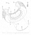
- a tire and air maintenance pump assembly 10 (forming an air maintenance tire or "AMT") includes a tire 12 and a vein pump assembly including a vein tube 26.
- AMT air maintenance tire
- the general operation of a peristaltic pump for use in a tire is described in US-B-8,113,254 and US-B-8,042,586 , which are incorporated herein in their entirety by reference.
- the tire is constructed to provide a tread region 14, a pair of sidewalls 16, 18 extending from opposite bead areas 22, 24 to the tire read region 14.
- the tire encloses a tire cavity 20.
- the air maintenance assembly includes an elongate air tube 26 that encloses an air passageway 28 that is preferably generally elliptical in cross-section.
- the tube 26 is preferably formed of a resilient, elastomeric flexible material such as plastic or rubber compounds and composites that are capable of withstanding repeated deformation cycles wherein the tube is deformed into a flattened condition subject to external force and, upon removal of such force, returns to an original condition generally circular in cross-section.
- the tube is of a diameter sufficient to operatively pass a volume of air sufficient for the purpose of maintaining air pressure within the cavity 20.
- the tube 26 is shown to follow a 180° semi-circular path in the configuration of FIG. 1 . However, other configurations, such as 360°annular tube, may be employed without departing from the invention.
- the air maintenance vein pump assembly further preferably includes an inlet device 30 and an outlet device 32 spaced apart approximately 180° at respective opposite end locations of the air tube 26.
- the outlet device 32 preferably has a T-shaped configuration in which T-forming sleeves connect to an end of the tube 26 and an outlet conduit conducts air from the tube to the tire cavity 20.
- the inlet device 30 likewise preferably is of a T-shaped configuration, connecting to an opposite end of the tube 28 and having an inlet conduit which intakes outside air into the tube passageway 28.
- the air tube 26, inlet device 30, and the outlet device 32 are positioned within an appropriately complementarily configured channel 34 within one or both of the tire sidewalls 16, 18.
- a footprint is formed against a ground surface (not shown).
- a compressive force is thus directed into the tire from the footprint and acts to flatten a segment of the air tube 26 and passageway 28.
- the air tube and passageway are sequentially flattened and pump air in the direction 36 shown. Flattening of the tube segment by segment thereby forces air from the inlet along tube passageway 28, until the pressurized air is directed from the outlet and into the tire cavity.
- Appropriate valve mechanism at the outlet will vent the air in the event that the tire cavity pressure is at or above the recommended tire pressure. Pumping of air occurs for one-half the revolution of the tire with the 180 degree air tube configuration shown.
- FIG. 10 shows an alternative 360° air tube which functions as described above, with the exception that air is pumped along the air tube in direction 72 for the entire 360° revolution of the tire.
- FIG. 4 shows a tire with two 180° peristaltic tubes as an alternative embodiment. In the FIG. 4 embodiment, the pump will function in either direction of tire rotation shown by the directional arrows. The two air tubes are each operational in a respective direction of rotation to pump air into the tire cavity.
- the check valve includes a cylindrical valve body, composed of any suitable rigid or semi-rigid material.
- the body has a rounded forward end rim.
- An array of outwardly directed retention ribs or flanges are spaced apart along the surface of the valve body, each retention rib angling to the rear of the body.
- a flexible membrane member is assembled into a central through passage of the cylindrical valve body.
- the membrane member includes a cylindrical membrane body captured within the valve body by in turned end flanges of the valve body.
- the membrane insert further includes a central projecting nose having a slit there through. The nose forms a gate through which pressurized air can flow in a forward direction but which prevents a back flow of air through the check valve in a rearward direction.
- Assembly of the check valves into the air tube may be made so as to create a segmented vein air tube.
- the check valves serve to avoid back flow, control air flow direction, and provide a simplified pump mechanism from compression ratio and pinching force to compression ratio only.
- the construction of an air pumping tube can be done by segmenting the tube and connecting opposite ends of each air tube segment to a check valve.
- An alternative assembly may be effected by means of specialized clamping and expansion of tube, insertion of the check valves to desired respective locations within the tube, whereby forming a complete air tube and check valve assembly. The assembly may then be inserted into a groove within the tire sidewall in a post-cure assembly procedure.
- US-2014/0110029 shows such an assembly sequence and method.
- the subject invention achieves yet a further alternative method of forming a peristaltic air pumping tube having a series of check valves positioned at intervals along the tube.
- the subject method of check valve placement includes the steps: extruding or molding a unitary tubing with one or more open section(s) or shaft(s) on the tube; inserting check valves after extrusion into each open section(s) or shaft(s) (green tube); closing the open section(s) or shaft(s) after the valves are inside the green tubing; and curing the green tubing to ensure a proper seal between the check valves and the tubing.
- the subject method avoids check valve connection to tubing post-cure; does not require a high deformation of tire sidewall to provide pumping; eliminates back flow; can accept tire/groove dimensional and/or geometrical variation or irregularity; can accept rim dimensional and/or geometrical variation or anomaly; achieves a higher efficiency in pumping than previous air tube construction methods; and eliminates dead-end air volume issues.
- a check valve insert body 42 of preferably generally cylindrical geometry is formed out of suitable elastomeric or rubber composition.
- the body 42 includes end walls 44, 46, and a through bore 48 preferably extending there through along a longitudinal axis.
- a valve chamber 49 dimensioned to receive a check valve 50.
- the check valve 50 preferably includes a rearwardly disposed seating collar 52 seated within the valve chamber 49 against an internal shoulder 56.
- a slotted conical membrane 58 preferably is secured to collar 52 and tapers inwardly forward into the chamber 49.
- the membrane 58 preferably includes peripheral slits spaced about a circumference that allow the membrane 58 to divergently open as shown in FIG.
- check valve component refers to the assembly constituting the check valve body 42 containing the check valve 50 therein.
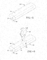
- FIGS. 5, 6 , 7 and 8 show an assembly sequence whereby multiple check valves 50 are assembled into the axial passageway 28 of the elastomeric flexible tube 26.
- the multiple check valves 50 each housed within a body 42, occupy spaced apart respective locations within the tube 26 in an orientation which facilitates a flow of pressurized air in a forward direction from the inlet device 30 to the outlet device 32 ( FIG. 9 ) but which prevents a back flow of pressurized air in the reverse direction.
- the peristaltic air tube 26 is formed having a preferably generally mushroom shaped sectional profile formed by a wide tube cap or lobe 64 and a smaller width underlying tube base 66.
- the air passageway 28 is preferably generally elliptical in section, having a longitudinal axis oriented along a transverse axis of the elongate air tube 28.
- the air passageway extends longitudinally co-extensive with the air tube 26 at a mid-air tube depth location generally where the cap 64 of the tube 26 intersects the base 66 of the tube.
- the tube 26 is formed of elastomeric material, preferably of rubber or composite rubber materials, by conventional means such as extrusion or molding.
- the tube 26 during check valve assembly is in its green (also referred herein as "pre-cured” or "uncured") form. Subsequently, the air tube 26 containing the check valves is cured and inserted into a complementary groove formed within a cured tire.
- the tube 26 has a length sufficient to extend an intended path about a lower region of a tire sidewall 16. In the path designated by FIG. 9 , the tube 26 follows a curvilinear path of 180°. Alternatively, as seen in FIG. 10 , the tube 26 and corresponding groove 34 may be formed in a 360° path so as to pump air cont inuously during each entire tire revolution.
- an access slug component 68 of the green tube 26 is removed after the tube is formed by means of an extrusion or molding. Removal of multiple slug components may be performed if desired, either in sequence or in unison.
- the slug component 68 is removed in the direction 70 and creates a portal 72 and access shaft 74 that extend into the cap 64 to a depth encompassing the depth of the air passageway 28 within the tube 26. Location of the access shaft 74 along the tube 26 is at a preselected location where placement of a check valve is desired.
- One or, preferably, multiple slug components 68 (one being shown in FIG.
- each slug component 68 removed leaves a shaft 74 that has a depth D sufficient to extend through the tube cap 64 and into the narrow tube base 66.
- Each slug component 68 has a width W and depth D closely complementing a check valve body to be inserted into the shaft vacated by the slug.
- the slug component 68 further has a depth sufficient to extend into the air tube 26 to a sufficient depth to reach the air passageway 28.
- the width and length of each slug component 68 corresponds to the width and length of the shaft 74 needed for insertion of a check valve device.
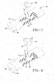
- FIG. 7 shows insertion of the check valve body 42 into the access shaft 74 and downward into a supportive check valve seat 76 at a lower terminal end of the shaft 74.
- Accurate control of the depth D of the slug component 68 places the check valve seat 76 and the check valve body 42 therein in an aligned location with the air passageway 28 of the tube 26.
- the length of the check valve body 42 preferably correlates with the length L of the slug component 68 such that the body 42, once inserted down the shaft 74 and into the seat 76, is co-extensive with the segment of passageway 28 removed by the removal of the slug component 68.
- FIG. 8 shows the check valve body 42 seated within the seat 76.
- the width and length W and L of the body 42 fills the void within the lower region of the shaft 74 vacated by the slug component 68. It will further be noted that, when seated, the check valve body 42 is located at a depth within the air tube 26 correlating with the depth of the air passageway 28. The shaft 74 thus extends to a depth at the intersection of the enlarged cap 64 of the air tube 26 and the narrower base 66 of the air tube body 26.
- a quadrilateral plug component 78 is inserted through the portal 72 and into the shaft 74 of the tube 26, substantially filling the void within shaft 74 vacated by slug component 68.
- the plug component 78 has a width W and length L facilitating a close fit insertion of the plug component into the shaft 74.
- the plug component 78 is preferably formed as a generally rectangular quadrilateral body and preferably includes a semi-cylindrical undercut 80 within a bottom plug component surface. The undercut 80 circumscribes the check valve body 42 seated within the seat 76, filling the void surrounding the body 42.
- the plug component 78 is preferably formed from green, uncured material composition matching the material composition of the air tube 26 or from a compatible material or composite capable of bonding with the material of air tube 26. Once the plug component 78 is fully inserted into the shaft 74, the air tube 26 is restored to its original external geometry.
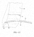
- the air tube 12 is oriented opposite the groove 34 within the lower region of sidewall 16.
- the groove 34 is formed having a sectional geometry complementary to the external geometry of the air tube 26.
- the opening to the groove 34 is enlarged by appropriate tooling (not shown).
- the air tube 26 then inserts into the groove 34 in an orientation in which the enlarged cap 64 is radially inwardmost within the groove and the narrower tube base 66 faces radially outward.
- FIG. 13 shows the fully inserted tube 26 within the sidewall groove.
- FIG. 14 The location of the completed air tube assembly into the lower region of tire sidewall 16 relative to the tire bead 22 is seen in section in FIG. 14, and FIG. 15 shows the same sectional view at a check valve location of the air tube assembly 26.
- the air tube 26 sequentially flattens for one half of the tire revolution and pumps air between the inlet 30 and outlet 32 and thereby into the tire cavity.
- the check valves within bodies 42 are spaced along the air tube 26 and oriented to allow air to flow in direction 36 but preclude back air flow in an opposite direction.
- a bidirectional pumping configuration for the air tube 26 may be deployed.
- the air tube 26 constitutes a 360° loop with the inlet device 30 and outlet device 32 180° opposite to each other.
- Check valve bodies 42 are spaced apart at preferred intervals along the 360° air tube 26.
- the air tube 26 sequentially flattens and unflattens segment by segment. Air is thus pumped bi-directionally along the air tube between the inlet and outlet devices 30, 32 and into the tire cavity.
- FIG. 11 shows yet a third alternative air tube configuration that allows for a uni-directional pumping of air along the air tube during a complete tire revolution.
- the inlet and outlet devices 30, 32 are locate proximally to each other at terminal ends of a 360° air tube loop.
- the check valve bodies 42 are spaced apart along the air tube extent. As the tire rotates in the rotation shown, the air tube 26 sequentially flattens and unflattens. Air is thereby pumped along the air tube 26 in direction 88 between inlet 30 and outlet 32 and then into the tire cavity.
- the subject invention provides an air pumping tube and tire system and method of assembling that is efficient and effective.
- the tire groove 34 is formed to extend into a flexing region of the tire sidewall 16 and the tire 12 is cured.
- the complementary air pumping tube 26, configured to insert into the tire groove, is adapted to accept check valves while in the green or uncured state.
- one or more access shaft(s) 74 are formed in the air pumping tube 26 to provide admittance of one or more check valve device(s) (42, 50) to a check valve seating depth, wherein in the check valve device(s) align with the air passageway 28.
- Plug components 78 of the system substantially fill each access shaft 74 after insertion of the check valve devices.
- Each access shaft 74 is formed by the removal of a slug component 68 from the air maintenance tube and filled subsequently by the insertion of a plug component 78.
- Check valve devices are thereby positioned along the air passageway and directionally allow air to flow in a specified direction but prevent the air from back flowing in an opposite direction.
- the check valves are inserted, and the plug component(s) placed in the air pumping tube in an uncured, green state. Subsequent to the placement and enclosure of the check valves within the air pumping tube by system plug components 78, the air pumping tube having the enclosed check valves is cured.
- the plug components 78, the outer body 42 of each check valve device, and the air pumping tube 26 are composed of compatible materials that bond together as result of the curing procedure. Post cure, the air pumping tube 26 containing the check valves are inserted into the sidewall groove 34 of the cured tire 12.
Applications Claiming Priority (1)
| Application Number | Priority Date | Filing Date | Title |
|---|---|---|---|
| US14/260,590 US9533533B2 (en) | 2014-04-24 | 2014-04-24 | Vein-style air pumping tube and tire system and method of assembly |
Publications (2)
| Publication Number | Publication Date |
|---|---|
| EP2937233A1 true EP2937233A1 (fr) | 2015-10-28 |
| EP2937233B1 EP2937233B1 (fr) | 2017-02-22 |
Family
ID=53175271
Family Applications (1)
| Application Number | Title | Priority Date | Filing Date |
|---|---|---|---|
| EP15164683.3A Active EP2937233B1 (fr) | 2014-04-24 | 2015-04-22 | Tube de pompage d'air à veine et système de pneu et procédé d'assemblage |
Country Status (5)
| Country | Link |
|---|---|
| US (1) | US9533533B2 (fr) |
| EP (1) | EP2937233B1 (fr) |
| JP (1) | JP6542020B2 (fr) |
| CN (1) | CN105034717B (fr) |
| BR (1) | BR102015008468B1 (fr) |
Families Citing this family (3)
| Publication number | Priority date | Publication date | Assignee | Title |
|---|---|---|---|---|
| US9421832B2 (en) * | 2013-02-04 | 2016-08-23 | The Goodyear Tire & Rubber Company | Air maintenance tire |
| US9233583B2 (en) * | 2013-12-11 | 2016-01-12 | The Goodyear Tire & Rubber Company | Tire apparatus |
| US10239368B2 (en) * | 2014-12-11 | 2019-03-26 | The Goodyear Tire & Rubber Company | Air maintenance tire and valve assembly |
Citations (5)
| Publication number | Priority date | Publication date | Assignee | Title |
|---|---|---|---|---|
| US8042586B2 (en) | 2009-12-21 | 2011-10-25 | The Goodyear Tire & Rubber Company | Self-inflating tire assembly |
| EP2384912A1 (fr) * | 2010-05-07 | 2011-11-09 | The Goodyear Tire & Rubber Company | Ensemble de pneu autogonflant |
| US8113254B2 (en) | 2009-12-21 | 2012-02-14 | The Goodyear Tire & Rubber Company | Self-inflating tire |
| EP2664467A1 (fr) * | 2012-05-14 | 2013-11-20 | The Goodyear Tire & Rubber Company | Assemblage de pneu de maintenance d'air de tube péristaltique et procédé |
| US20140110029A1 (en) | 2012-10-24 | 2014-04-24 | Robert Leon Benedict | Vein pump assembly for air maintenance tire |
Family Cites Families (19)
| Publication number | Priority date | Publication date | Assignee | Title |
|---|---|---|---|---|
| US1050886A (en) | 1910-02-23 | 1913-01-21 | Anson B Wetherell | Vehicle-tire. |
| US1134361A (en) | 1912-02-13 | 1915-04-06 | Anson B Wetherell | Self-filling tire. |
| US1682922A (en) | 1924-07-23 | 1928-09-04 | Charles W Mckone | Rubber-tire-bead construction |
| GB1086512A (en) | 1964-02-24 | 1967-10-11 | Ronald Leslie Sheppard | Improvements in or relating to pneumatic tyres |
| US3833041A (en) | 1973-10-11 | 1974-09-03 | Aerojet General Co | Tire inflator |
| DE3433318A1 (de) | 1984-09-11 | 1986-03-20 | Mousiol, Hans, 6000 Frankfurt | Verfahren zum aufpumpen von luftreifen und luftreifen fuer das verfahren |
| IT209132Z2 (it) | 1986-03-04 | 1988-09-12 | Bridgeport Brass Spa | Perfezionamenti a valvole per pneumatici di tipo tubeless. |
| FR2618102B1 (fr) | 1987-07-15 | 1990-02-16 | Michelin & Cie | Gonflage d'un pneumatique en rotation |
| RU2106978C1 (ru) | 1995-02-15 | 1998-03-20 | Леонид Михайлович Раткевич | Пневматическая шина с автоматической подкачкой воздуха |
| AU2002361924A1 (en) | 2001-12-11 | 2003-06-23 | Frantisek Hrabal | Device for monitoring, maintenance and adjustment of pressure in a tyre |
| DE10335244A1 (de) | 2003-08-01 | 2005-03-10 | Bayerische Motoren Werke Ag | Vorrichtung zur Luftbefüllung eines rotierenden Luftreifens |
| CZ303718B6 (cs) | 2006-05-23 | 2013-04-03 | Sithold S.R.O. | Komponenta s tvarovou pametí pro upravení tlaku v pneumatice a zpusob její výroby |
| US8327897B2 (en) | 2008-06-03 | 2012-12-11 | David A Firestone | Automatic tire sealing and inflating system |
| SE532584C2 (sv) | 2008-07-15 | 2010-02-23 | Jan Folke Wallenius | Fordonsdäck med en ventilanordning |
| US8186402B2 (en) | 2009-03-24 | 2012-05-29 | Pressure Sentinel, Inc | Device for automatically maintaining tire pressure |
| US8534335B2 (en) | 2010-09-27 | 2013-09-17 | The Goodyear Tire & Rubber Company | Distributed pump self-inflating tire assembly |
| US8695661B2 (en) * | 2011-07-15 | 2014-04-15 | The Goodyear Tire & Rubber Company | Air maintenance pumping tube and tire assembly |
| US8960249B2 (en) * | 2012-10-15 | 2015-02-24 | The Goodyear Tire & Rubber Company | Self-inflating tire |
| US9199518B2 (en) * | 2012-10-24 | 2015-12-01 | The Goodyear Tire & Rubber Company | Method of assemblying a segmented vein air pump in a tire |
-
2014
- 2014-04-24 US US14/260,590 patent/US9533533B2/en active Active
-
2015
- 2015-04-15 BR BR102015008468-4A patent/BR102015008468B1/pt active IP Right Grant
- 2015-04-20 JP JP2015085627A patent/JP6542020B2/ja active Active
- 2015-04-22 EP EP15164683.3A patent/EP2937233B1/fr active Active
- 2015-04-24 CN CN201510199034.2A patent/CN105034717B/zh active Active
Patent Citations (5)
| Publication number | Priority date | Publication date | Assignee | Title |
|---|---|---|---|---|
| US8042586B2 (en) | 2009-12-21 | 2011-10-25 | The Goodyear Tire & Rubber Company | Self-inflating tire assembly |
| US8113254B2 (en) | 2009-12-21 | 2012-02-14 | The Goodyear Tire & Rubber Company | Self-inflating tire |
| EP2384912A1 (fr) * | 2010-05-07 | 2011-11-09 | The Goodyear Tire & Rubber Company | Ensemble de pneu autogonflant |
| EP2664467A1 (fr) * | 2012-05-14 | 2013-11-20 | The Goodyear Tire & Rubber Company | Assemblage de pneu de maintenance d'air de tube péristaltique et procédé |
| US20140110029A1 (en) | 2012-10-24 | 2014-04-24 | Robert Leon Benedict | Vein pump assembly for air maintenance tire |
Also Published As
| Publication number | Publication date |
|---|---|
| BR102015008468A2 (pt) | 2016-04-26 |
| CN105034717B (zh) | 2017-05-03 |
| JP2015209204A (ja) | 2015-11-24 |
| CN105034717A (zh) | 2015-11-11 |
| JP6542020B2 (ja) | 2019-07-10 |
| US20150306924A1 (en) | 2015-10-29 |
| BR102015008468B1 (pt) | 2021-03-30 |
| US9533533B2 (en) | 2017-01-03 |
| EP2937233B1 (fr) | 2017-02-22 |
Similar Documents
| Publication | Publication Date | Title |
|---|---|---|
| EP2578420B1 (fr) | Pneu comprenant un ensemble tube et procédé d'assemblage d'un tube d'air allongé à l'intérieur d'un pneumatique | |
| EP2455239B1 (fr) | Ensemble de pompe en ligne pour pneu autogonflant | |
| JP6215650B2 (ja) | 空気維持タイヤ用のヴァインポンプ組立体 | |
| US9199518B2 (en) | Method of assemblying a segmented vein air pump in a tire | |
| EP2565061B1 (fr) | Pneu autogonflant et régulateur de pression pneumatique | |
| US9669671B2 (en) | Vein pump assembly for air maintenance tire | |
| EP2565060A1 (fr) | Pneu autogonflant | |
| EP2565059A2 (fr) | Pneu | |
| EP2543524A1 (fr) | Ensemble de pompage de maintenance d'air et pneu | |
| EP2546083A1 (fr) | Tube de pompage d'entretien d'air et ensemble de pneu | |
| EP2937233B1 (fr) | Tube de pompage d'air à veine et système de pneu et procédé d'assemblage | |
| US9056435B2 (en) | Securing to a pneumatic tire | |
| EP2883718B1 (fr) | Pneumatique autogonflant avec pompe hybride | |
| JP2015034005A (ja) | 空気維持タイヤ用の弁組立体 | |
| EP2607109A2 (fr) | Pneu comprenant un ensemble connecteur et procédé de fabrication | |
| EP2455240B1 (fr) | Procédé de fabrication d'un pneu autogonflant | |
| EP2724874B1 (fr) | Pneu autogonflant et procédé d'assemblage | |
| EP3031633B1 (fr) | Pneumatique de maintenance d'air et ensemble de soupape | |
| EP2987658A1 (fr) | Pneu à maintenance d'air et procédé de fabrication | |
| EP2607108A2 (fr) | Pneu et procédé de formation d'un passage d'air dans un pneu |
Legal Events
| Date | Code | Title | Description |
|---|---|---|---|
| PUAI | Public reference made under article 153(3) epc to a published international application that has entered the european phase |
Free format text: ORIGINAL CODE: 0009012 |
|
| AK | Designated contracting states |
Kind code of ref document: A1 Designated state(s): AL AT BE BG CH CY CZ DE DK EE ES FI FR GB GR HR HU IE IS IT LI LT LU LV MC MK MT NL NO PL PT RO RS SE SI SK SM TR |
|
| AX | Request for extension of the european patent |
Extension state: BA ME |
|
| 17P | Request for examination filed |
Effective date: 20160428 |
|
| RBV | Designated contracting states (corrected) |
Designated state(s): AL AT BE BG CH CY CZ DE DK EE ES FI FR GB GR HR HU IE IS IT LI LT LU LV MC MK MT NL NO PL PT RO RS SE SI SK SM TR |
|
| GRAP | Despatch of communication of intention to grant a patent |
Free format text: ORIGINAL CODE: EPIDOSNIGR1 |
|
| RIC1 | Information provided on ipc code assigned before grant |
Ipc: B60C 23/12 20060101AFI20160812BHEP |
|
| INTG | Intention to grant announced |
Effective date: 20160921 |
|
| GRAS | Grant fee paid |
Free format text: ORIGINAL CODE: EPIDOSNIGR3 |
|
| GRAA | (expected) grant |
Free format text: ORIGINAL CODE: 0009210 |
|
| AK | Designated contracting states |
Kind code of ref document: B1 Designated state(s): AL AT BE BG CH CY CZ DE DK EE ES FI FR GB GR HR HU IE IS IT LI LT LU LV MC MK MT NL NO PL PT RO RS SE SI SK SM TR |
|
| REG | Reference to a national code |
Ref country code: GB Ref legal event code: FG4D |
|
| REG | Reference to a national code |
Ref country code: CH Ref legal event code: EP |
|
| REG | Reference to a national code |
Ref country code: AT Ref legal event code: REF Ref document number: 868985 Country of ref document: AT Kind code of ref document: T Effective date: 20170315 |
|
| REG | Reference to a national code |
Ref country code: IE Ref legal event code: FG4D Ref country code: FR Ref legal event code: PLFP Year of fee payment: 3 |
|
| REG | Reference to a national code |
Ref country code: DE Ref legal event code: R096 Ref document number: 602015001534 Country of ref document: DE |
|
| REG | Reference to a national code |
Ref country code: LT Ref legal event code: MG4D |
|
| REG | Reference to a national code |
Ref country code: NL Ref legal event code: MP Effective date: 20170222 |
|
| REG | Reference to a national code |
Ref country code: AT Ref legal event code: MK05 Ref document number: 868985 Country of ref document: AT Kind code of ref document: T Effective date: 20170222 |
|
| PG25 | Lapsed in a contracting state [announced via postgrant information from national office to epo] |
Ref country code: HR Free format text: LAPSE BECAUSE OF FAILURE TO SUBMIT A TRANSLATION OF THE DESCRIPTION OR TO PAY THE FEE WITHIN THE PRESCRIBED TIME-LIMIT Effective date: 20170222 Ref country code: FI Free format text: LAPSE BECAUSE OF FAILURE TO SUBMIT A TRANSLATION OF THE DESCRIPTION OR TO PAY THE FEE WITHIN THE PRESCRIBED TIME-LIMIT Effective date: 20170222 Ref country code: GR Free format text: LAPSE BECAUSE OF FAILURE TO SUBMIT A TRANSLATION OF THE DESCRIPTION OR TO PAY THE FEE WITHIN THE PRESCRIBED TIME-LIMIT Effective date: 20170523 Ref country code: NO Free format text: LAPSE BECAUSE OF FAILURE TO SUBMIT A TRANSLATION OF THE DESCRIPTION OR TO PAY THE FEE WITHIN THE PRESCRIBED TIME-LIMIT Effective date: 20170522 Ref country code: LT Free format text: LAPSE BECAUSE OF FAILURE TO SUBMIT A TRANSLATION OF THE DESCRIPTION OR TO PAY THE FEE WITHIN THE PRESCRIBED TIME-LIMIT Effective date: 20170222 |
|
| PG25 | Lapsed in a contracting state [announced via postgrant information from national office to epo] |
Ref country code: ES Free format text: LAPSE BECAUSE OF FAILURE TO SUBMIT A TRANSLATION OF THE DESCRIPTION OR TO PAY THE FEE WITHIN THE PRESCRIBED TIME-LIMIT Effective date: 20170222 Ref country code: SE Free format text: LAPSE BECAUSE OF FAILURE TO SUBMIT A TRANSLATION OF THE DESCRIPTION OR TO PAY THE FEE WITHIN THE PRESCRIBED TIME-LIMIT Effective date: 20170222 Ref country code: AT Free format text: LAPSE BECAUSE OF FAILURE TO SUBMIT A TRANSLATION OF THE DESCRIPTION OR TO PAY THE FEE WITHIN THE PRESCRIBED TIME-LIMIT Effective date: 20170222 Ref country code: RS Free format text: LAPSE BECAUSE OF FAILURE TO SUBMIT A TRANSLATION OF THE DESCRIPTION OR TO PAY THE FEE WITHIN THE PRESCRIBED TIME-LIMIT Effective date: 20170222 Ref country code: NL Free format text: LAPSE BECAUSE OF NON-PAYMENT OF DUE FEES Effective date: 20170222 Ref country code: PT Free format text: LAPSE BECAUSE OF FAILURE TO SUBMIT A TRANSLATION OF THE DESCRIPTION OR TO PAY THE FEE WITHIN THE PRESCRIBED TIME-LIMIT Effective date: 20170622 Ref country code: BG Free format text: LAPSE BECAUSE OF FAILURE TO SUBMIT A TRANSLATION OF THE DESCRIPTION OR TO PAY THE FEE WITHIN THE PRESCRIBED TIME-LIMIT Effective date: 20170522 Ref country code: LV Free format text: LAPSE BECAUSE OF FAILURE TO SUBMIT A TRANSLATION OF THE DESCRIPTION OR TO PAY THE FEE WITHIN THE PRESCRIBED TIME-LIMIT Effective date: 20170222 |
|
| PG25 | Lapsed in a contracting state [announced via postgrant information from national office to epo] |
Ref country code: EE Free format text: LAPSE BECAUSE OF FAILURE TO SUBMIT A TRANSLATION OF THE DESCRIPTION OR TO PAY THE FEE WITHIN THE PRESCRIBED TIME-LIMIT Effective date: 20170222 Ref country code: RO Free format text: LAPSE BECAUSE OF FAILURE TO SUBMIT A TRANSLATION OF THE DESCRIPTION OR TO PAY THE FEE WITHIN THE PRESCRIBED TIME-LIMIT Effective date: 20170222 Ref country code: SK Free format text: LAPSE BECAUSE OF FAILURE TO SUBMIT A TRANSLATION OF THE DESCRIPTION OR TO PAY THE FEE WITHIN THE PRESCRIBED TIME-LIMIT Effective date: 20170222 Ref country code: CZ Free format text: LAPSE BECAUSE OF FAILURE TO SUBMIT A TRANSLATION OF THE DESCRIPTION OR TO PAY THE FEE WITHIN THE PRESCRIBED TIME-LIMIT Effective date: 20170222 |
|
| REG | Reference to a national code |
Ref country code: DE Ref legal event code: R097 Ref document number: 602015001534 Country of ref document: DE |
|
| PG25 | Lapsed in a contracting state [announced via postgrant information from national office to epo] |
Ref country code: SM Free format text: LAPSE BECAUSE OF FAILURE TO SUBMIT A TRANSLATION OF THE DESCRIPTION OR TO PAY THE FEE WITHIN THE PRESCRIBED TIME-LIMIT Effective date: 20170222 Ref country code: PL Free format text: LAPSE BECAUSE OF FAILURE TO SUBMIT A TRANSLATION OF THE DESCRIPTION OR TO PAY THE FEE WITHIN THE PRESCRIBED TIME-LIMIT Effective date: 20170222 Ref country code: DK Free format text: LAPSE BECAUSE OF FAILURE TO SUBMIT A TRANSLATION OF THE DESCRIPTION OR TO PAY THE FEE WITHIN THE PRESCRIBED TIME-LIMIT Effective date: 20170222 |
|
| PLBE | No opposition filed within time limit |
Free format text: ORIGINAL CODE: 0009261 |
|
| STAA | Information on the status of an ep patent application or granted ep patent |
Free format text: STATUS: NO OPPOSITION FILED WITHIN TIME LIMIT |
|
| REG | Reference to a national code |
Ref country code: IE Ref legal event code: MM4A |
|
| 26N | No opposition filed |
Effective date: 20171123 |
|
| PG25 | Lapsed in a contracting state [announced via postgrant information from national office to epo] |
Ref country code: MC Free format text: LAPSE BECAUSE OF FAILURE TO SUBMIT A TRANSLATION OF THE DESCRIPTION OR TO PAY THE FEE WITHIN THE PRESCRIBED TIME-LIMIT Effective date: 20170222 |
|
| PG25 | Lapsed in a contracting state [announced via postgrant information from national office to epo] |
Ref country code: LU Free format text: LAPSE BECAUSE OF NON-PAYMENT OF DUE FEES Effective date: 20170422 Ref country code: SI Free format text: LAPSE BECAUSE OF FAILURE TO SUBMIT A TRANSLATION OF THE DESCRIPTION OR TO PAY THE FEE WITHIN THE PRESCRIBED TIME-LIMIT Effective date: 20170222 |
|
| REG | Reference to a national code |
Ref country code: BE Ref legal event code: MM Effective date: 20170430 |
|
| REG | Reference to a national code |
Ref country code: FR Ref legal event code: PLFP Year of fee payment: 4 |
|
| PG25 | Lapsed in a contracting state [announced via postgrant information from national office to epo] |
Ref country code: IE Free format text: LAPSE BECAUSE OF NON-PAYMENT OF DUE FEES Effective date: 20170422 |
|
| PG25 | Lapsed in a contracting state [announced via postgrant information from national office to epo] |
Ref country code: BE Free format text: LAPSE BECAUSE OF NON-PAYMENT OF DUE FEES Effective date: 20170430 |
|
| PG25 | Lapsed in a contracting state [announced via postgrant information from national office to epo] |
Ref country code: MT Free format text: LAPSE BECAUSE OF NON-PAYMENT OF DUE FEES Effective date: 20170422 |
|
| REG | Reference to a national code |
Ref country code: CH Ref legal event code: PL |
|
| PG25 | Lapsed in a contracting state [announced via postgrant information from national office to epo] |
Ref country code: CH Free format text: LAPSE BECAUSE OF NON-PAYMENT OF DUE FEES Effective date: 20180430 Ref country code: LI Free format text: LAPSE BECAUSE OF NON-PAYMENT OF DUE FEES Effective date: 20180430 |
|
| PG25 | Lapsed in a contracting state [announced via postgrant information from national office to epo] |
Ref country code: HU Free format text: LAPSE BECAUSE OF FAILURE TO SUBMIT A TRANSLATION OF THE DESCRIPTION OR TO PAY THE FEE WITHIN THE PRESCRIBED TIME-LIMIT; INVALID AB INITIO Effective date: 20150422 |
|
| PG25 | Lapsed in a contracting state [announced via postgrant information from national office to epo] |
Ref country code: CY Free format text: LAPSE BECAUSE OF FAILURE TO SUBMIT A TRANSLATION OF THE DESCRIPTION OR TO PAY THE FEE WITHIN THE PRESCRIBED TIME-LIMIT Effective date: 20170222 |
|
| PG25 | Lapsed in a contracting state [announced via postgrant information from national office to epo] |
Ref country code: MK Free format text: LAPSE BECAUSE OF FAILURE TO SUBMIT A TRANSLATION OF THE DESCRIPTION OR TO PAY THE FEE WITHIN THE PRESCRIBED TIME-LIMIT Effective date: 20170222 |
|
| GBPC | Gb: european patent ceased through non-payment of renewal fee |
Effective date: 20190422 |
|
| PG25 | Lapsed in a contracting state [announced via postgrant information from national office to epo] |
Ref country code: GB Free format text: LAPSE BECAUSE OF NON-PAYMENT OF DUE FEES Effective date: 20190422 |
|
| PG25 | Lapsed in a contracting state [announced via postgrant information from national office to epo] |
Ref country code: TR Free format text: LAPSE BECAUSE OF FAILURE TO SUBMIT A TRANSLATION OF THE DESCRIPTION OR TO PAY THE FEE WITHIN THE PRESCRIBED TIME-LIMIT Effective date: 20170222 |
|
| PG25 | Lapsed in a contracting state [announced via postgrant information from national office to epo] |
Ref country code: AL Free format text: LAPSE BECAUSE OF FAILURE TO SUBMIT A TRANSLATION OF THE DESCRIPTION OR TO PAY THE FEE WITHIN THE PRESCRIBED TIME-LIMIT Effective date: 20170222 Ref country code: IS Free format text: LAPSE BECAUSE OF FAILURE TO SUBMIT A TRANSLATION OF THE DESCRIPTION OR TO PAY THE FEE WITHIN THE PRESCRIBED TIME-LIMIT Effective date: 20170622 |
|
| PGFP | Annual fee paid to national office [announced via postgrant information from national office to epo] |
Ref country code: FR Payment date: 20230309 Year of fee payment: 9 |
|
| PGFP | Annual fee paid to national office [announced via postgrant information from national office to epo] |
Ref country code: IT Payment date: 20230310 Year of fee payment: 9 |
|
| PGFP | Annual fee paid to national office [announced via postgrant information from national office to epo] |
Ref country code: DE Payment date: 20230307 Year of fee payment: 9 |