EP2937233A1 - Vein-style air pumping tube and tire system and method of assembly - Google Patents
Vein-style air pumping tube and tire system and method of assembly Download PDFInfo
- Publication number
- EP2937233A1 EP2937233A1 EP15164683.3A EP15164683A EP2937233A1 EP 2937233 A1 EP2937233 A1 EP 2937233A1 EP 15164683 A EP15164683 A EP 15164683A EP 2937233 A1 EP2937233 A1 EP 2937233A1
- Authority
- EP
- European Patent Office
- Prior art keywords
- tube
- air
- check valve
- tire
- access shaft
- Prior art date
- Legal status (The legal status is an assumption and is not a legal conclusion. Google has not performed a legal analysis and makes no representation as to the accuracy of the status listed.)
- Granted
Links
Images


Classifications
-
- B—PERFORMING OPERATIONS; TRANSPORTING
- B60—VEHICLES IN GENERAL
- B60C—VEHICLE TYRES; TYRE INFLATION; TYRE CHANGING; CONNECTING VALVES TO INFLATABLE ELASTIC BODIES IN GENERAL; DEVICES OR ARRANGEMENTS RELATED TO TYRES
- B60C23/00—Devices for measuring, signalling, controlling, or distributing tyre pressure or temperature, specially adapted for mounting on vehicles; Arrangement of tyre inflating devices on vehicles, e.g. of pumps or of tanks; Tyre cooling arrangements
- B60C23/001—Devices for manually or automatically controlling or distributing tyre pressure whilst the vehicle is moving
- B60C23/004—Devices for manually or automatically controlling or distributing tyre pressure whilst the vehicle is moving the control being done on the wheel, e.g. using a wheel-mounted reservoir
-
- B—PERFORMING OPERATIONS; TRANSPORTING
- B60—VEHICLES IN GENERAL
- B60C—VEHICLE TYRES; TYRE INFLATION; TYRE CHANGING; CONNECTING VALVES TO INFLATABLE ELASTIC BODIES IN GENERAL; DEVICES OR ARRANGEMENTS RELATED TO TYRES
- B60C23/00—Devices for measuring, signalling, controlling, or distributing tyre pressure or temperature, specially adapted for mounting on vehicles; Arrangement of tyre inflating devices on vehicles, e.g. of pumps or of tanks; Tyre cooling arrangements
- B60C23/10—Arrangement of tyre-inflating pumps mounted on vehicles
- B60C23/12—Arrangement of tyre-inflating pumps mounted on vehicles operated by a running wheel
- B60C23/121—Arrangement of tyre-inflating pumps mounted on vehicles operated by a running wheel the pumps being mounted on the tyres
- B60C23/123—Elongate peristaltic pumps
-
- B—PERFORMING OPERATIONS; TRANSPORTING
- B60—VEHICLES IN GENERAL
- B60C—VEHICLE TYRES; TYRE INFLATION; TYRE CHANGING; CONNECTING VALVES TO INFLATABLE ELASTIC BODIES IN GENERAL; DEVICES OR ARRANGEMENTS RELATED TO TYRES
- B60C23/00—Devices for measuring, signalling, controlling, or distributing tyre pressure or temperature, specially adapted for mounting on vehicles; Arrangement of tyre inflating devices on vehicles, e.g. of pumps or of tanks; Tyre cooling arrangements
- B60C23/10—Arrangement of tyre-inflating pumps mounted on vehicles
- B60C23/12—Arrangement of tyre-inflating pumps mounted on vehicles operated by a running wheel
- B60C23/135—Arrangement of tyre-inflating pumps mounted on vehicles operated by a running wheel activated due to tyre deformation
Definitions
- the invention relates generally to air maintenance systems for a tire and, more specifically, to such systems that assemble an air pump apparatus into a tire in order to pump air into the tire as the tire rotates.
- the invention relates to an air maintenance tire in accordance with claim 1 and to a method in accordance with claim 9.
- an air pumping tube and tire system and method of assembling in which a tire groove is formed to extend into a flexing region of a tire sidewall and a complementary air pumping tube inserts into the tire groove.
- one or more access shaft(s) are formed in the air pumping tube to provide admittance of one or more check valve device(s) to a check valve seating depth, wherein in the check valve device(s) align with the air passageway.
- a plug component of the system substantially fills each access shaft after insertion of the check valve devices.
- Each access shaft is formed by the removal of a slug component from the air maintenance tube which is replaced by a shaft-residing plug component.
- the air pumping tube is configured having a mushroom sectional configuration comprising a larger diameter tube cap and an adjoining smaller diameter tube base.
- the air passageway resides along a mid-region of the air pumping tube at the intersection of the cap and base of the air pumping tube.
- the air passageway is elliptical in sectional configuration and oriented to extend in a longitudinal axial direction between the tube cap and the tube base.
- the slug component(s) are removed, the check valves inserted, and the plug component(s) placed with the air pumping tube in an uncured condition. Subsequent to placement and enclosure of the check valves within the air pumping tube by system plug components, the air pumping tube is cured.
- the plug components, the outer body of each check valve device, and the air pumping tube are composed of compatible materials that bond together as result of the curing procedure. Post cure, the air pumping tube containing the check valves are inserted into the sidewall groove of the cured tire.
- Axial and “axially” means lines or directions that are parallel to the axis of rotation of the tire.
- “Circumferential” means lines or directions extending along the perimeter of the surface of the annular tread perpendicular to the axial direction.
- “Footprint” means the contact patch or area of contact of the tire tread with a flat surface at zero speed and under normal load and pressure.
- “Lateral” means an axial direction.
- Periodaltic means operating by means of wave-like contractions that propel contained matter, such as air, along tubular pathways.
- Ring and radially means directions radially toward or away from the axis of rotation of the tire.
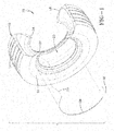
- a tire and air maintenance pump assembly 10 (forming an air maintenance tire or "AMT") includes a tire 12 and a vein pump assembly including a vein tube 26.
- AMT air maintenance tire
- the general operation of a peristaltic pump for use in a tire is described in US-B-8,113,254 and US-B-8,042,586 , which are incorporated herein in their entirety by reference.
- the tire is constructed to provide a tread region 14, a pair of sidewalls 16, 18 extending from opposite bead areas 22, 24 to the tire read region 14.
- the tire encloses a tire cavity 20.
- the air maintenance assembly includes an elongate air tube 26 that encloses an air passageway 28 that is preferably generally elliptical in cross-section.
- the tube 26 is preferably formed of a resilient, elastomeric flexible material such as plastic or rubber compounds and composites that are capable of withstanding repeated deformation cycles wherein the tube is deformed into a flattened condition subject to external force and, upon removal of such force, returns to an original condition generally circular in cross-section.
- the tube is of a diameter sufficient to operatively pass a volume of air sufficient for the purpose of maintaining air pressure within the cavity 20.
- the tube 26 is shown to follow a 180° semi-circular path in the configuration of FIG. 1 . However, other configurations, such as 360°annular tube, may be employed without departing from the invention.
- the air maintenance vein pump assembly further preferably includes an inlet device 30 and an outlet device 32 spaced apart approximately 180° at respective opposite end locations of the air tube 26.
- the outlet device 32 preferably has a T-shaped configuration in which T-forming sleeves connect to an end of the tube 26 and an outlet conduit conducts air from the tube to the tire cavity 20.
- the inlet device 30 likewise preferably is of a T-shaped configuration, connecting to an opposite end of the tube 28 and having an inlet conduit which intakes outside air into the tube passageway 28.
- the air tube 26, inlet device 30, and the outlet device 32 are positioned within an appropriately complementarily configured channel 34 within one or both of the tire sidewalls 16, 18.
- a footprint is formed against a ground surface (not shown).
- a compressive force is thus directed into the tire from the footprint and acts to flatten a segment of the air tube 26 and passageway 28.
- the air tube and passageway are sequentially flattened and pump air in the direction 36 shown. Flattening of the tube segment by segment thereby forces air from the inlet along tube passageway 28, until the pressurized air is directed from the outlet and into the tire cavity.
- Appropriate valve mechanism at the outlet will vent the air in the event that the tire cavity pressure is at or above the recommended tire pressure. Pumping of air occurs for one-half the revolution of the tire with the 180 degree air tube configuration shown.
- FIG. 10 shows an alternative 360° air tube which functions as described above, with the exception that air is pumped along the air tube in direction 72 for the entire 360° revolution of the tire.
- FIG. 4 shows a tire with two 180° peristaltic tubes as an alternative embodiment. In the FIG. 4 embodiment, the pump will function in either direction of tire rotation shown by the directional arrows. The two air tubes are each operational in a respective direction of rotation to pump air into the tire cavity.
- the check valve includes a cylindrical valve body, composed of any suitable rigid or semi-rigid material.
- the body has a rounded forward end rim.
- An array of outwardly directed retention ribs or flanges are spaced apart along the surface of the valve body, each retention rib angling to the rear of the body.
- a flexible membrane member is assembled into a central through passage of the cylindrical valve body.
- the membrane member includes a cylindrical membrane body captured within the valve body by in turned end flanges of the valve body.
- the membrane insert further includes a central projecting nose having a slit there through. The nose forms a gate through which pressurized air can flow in a forward direction but which prevents a back flow of air through the check valve in a rearward direction.
- Assembly of the check valves into the air tube may be made so as to create a segmented vein air tube.
- the check valves serve to avoid back flow, control air flow direction, and provide a simplified pump mechanism from compression ratio and pinching force to compression ratio only.
- the construction of an air pumping tube can be done by segmenting the tube and connecting opposite ends of each air tube segment to a check valve.
- An alternative assembly may be effected by means of specialized clamping and expansion of tube, insertion of the check valves to desired respective locations within the tube, whereby forming a complete air tube and check valve assembly. The assembly may then be inserted into a groove within the tire sidewall in a post-cure assembly procedure.
- US-2014/0110029 shows such an assembly sequence and method.
- the subject invention achieves yet a further alternative method of forming a peristaltic air pumping tube having a series of check valves positioned at intervals along the tube.
- the subject method of check valve placement includes the steps: extruding or molding a unitary tubing with one or more open section(s) or shaft(s) on the tube; inserting check valves after extrusion into each open section(s) or shaft(s) (green tube); closing the open section(s) or shaft(s) after the valves are inside the green tubing; and curing the green tubing to ensure a proper seal between the check valves and the tubing.
- the subject method avoids check valve connection to tubing post-cure; does not require a high deformation of tire sidewall to provide pumping; eliminates back flow; can accept tire/groove dimensional and/or geometrical variation or irregularity; can accept rim dimensional and/or geometrical variation or anomaly; achieves a higher efficiency in pumping than previous air tube construction methods; and eliminates dead-end air volume issues.
- a check valve insert body 42 of preferably generally cylindrical geometry is formed out of suitable elastomeric or rubber composition.
- the body 42 includes end walls 44, 46, and a through bore 48 preferably extending there through along a longitudinal axis.
- a valve chamber 49 dimensioned to receive a check valve 50.
- the check valve 50 preferably includes a rearwardly disposed seating collar 52 seated within the valve chamber 49 against an internal shoulder 56.
- a slotted conical membrane 58 preferably is secured to collar 52 and tapers inwardly forward into the chamber 49.
- the membrane 58 preferably includes peripheral slits spaced about a circumference that allow the membrane 58 to divergently open as shown in FIG.
- check valve component refers to the assembly constituting the check valve body 42 containing the check valve 50 therein.
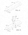
- FIGS. 5, 6 , 7 and 8 show an assembly sequence whereby multiple check valves 50 are assembled into the axial passageway 28 of the elastomeric flexible tube 26.
- the multiple check valves 50 each housed within a body 42, occupy spaced apart respective locations within the tube 26 in an orientation which facilitates a flow of pressurized air in a forward direction from the inlet device 30 to the outlet device 32 ( FIG. 9 ) but which prevents a back flow of pressurized air in the reverse direction.
- the peristaltic air tube 26 is formed having a preferably generally mushroom shaped sectional profile formed by a wide tube cap or lobe 64 and a smaller width underlying tube base 66.
- the air passageway 28 is preferably generally elliptical in section, having a longitudinal axis oriented along a transverse axis of the elongate air tube 28.
- the air passageway extends longitudinally co-extensive with the air tube 26 at a mid-air tube depth location generally where the cap 64 of the tube 26 intersects the base 66 of the tube.
- the tube 26 is formed of elastomeric material, preferably of rubber or composite rubber materials, by conventional means such as extrusion or molding.
- the tube 26 during check valve assembly is in its green (also referred herein as "pre-cured” or "uncured") form. Subsequently, the air tube 26 containing the check valves is cured and inserted into a complementary groove formed within a cured tire.
- the tube 26 has a length sufficient to extend an intended path about a lower region of a tire sidewall 16. In the path designated by FIG. 9 , the tube 26 follows a curvilinear path of 180°. Alternatively, as seen in FIG. 10 , the tube 26 and corresponding groove 34 may be formed in a 360° path so as to pump air cont inuously during each entire tire revolution.
- an access slug component 68 of the green tube 26 is removed after the tube is formed by means of an extrusion or molding. Removal of multiple slug components may be performed if desired, either in sequence or in unison.
- the slug component 68 is removed in the direction 70 and creates a portal 72 and access shaft 74 that extend into the cap 64 to a depth encompassing the depth of the air passageway 28 within the tube 26. Location of the access shaft 74 along the tube 26 is at a preselected location where placement of a check valve is desired.
- One or, preferably, multiple slug components 68 (one being shown in FIG.
- each slug component 68 removed leaves a shaft 74 that has a depth D sufficient to extend through the tube cap 64 and into the narrow tube base 66.
- Each slug component 68 has a width W and depth D closely complementing a check valve body to be inserted into the shaft vacated by the slug.
- the slug component 68 further has a depth sufficient to extend into the air tube 26 to a sufficient depth to reach the air passageway 28.
- the width and length of each slug component 68 corresponds to the width and length of the shaft 74 needed for insertion of a check valve device.
- FIG. 7 shows insertion of the check valve body 42 into the access shaft 74 and downward into a supportive check valve seat 76 at a lower terminal end of the shaft 74.
- Accurate control of the depth D of the slug component 68 places the check valve seat 76 and the check valve body 42 therein in an aligned location with the air passageway 28 of the tube 26.
- the length of the check valve body 42 preferably correlates with the length L of the slug component 68 such that the body 42, once inserted down the shaft 74 and into the seat 76, is co-extensive with the segment of passageway 28 removed by the removal of the slug component 68.
- FIG. 8 shows the check valve body 42 seated within the seat 76.
- the width and length W and L of the body 42 fills the void within the lower region of the shaft 74 vacated by the slug component 68. It will further be noted that, when seated, the check valve body 42 is located at a depth within the air tube 26 correlating with the depth of the air passageway 28. The shaft 74 thus extends to a depth at the intersection of the enlarged cap 64 of the air tube 26 and the narrower base 66 of the air tube body 26.
- a quadrilateral plug component 78 is inserted through the portal 72 and into the shaft 74 of the tube 26, substantially filling the void within shaft 74 vacated by slug component 68.
- the plug component 78 has a width W and length L facilitating a close fit insertion of the plug component into the shaft 74.
- the plug component 78 is preferably formed as a generally rectangular quadrilateral body and preferably includes a semi-cylindrical undercut 80 within a bottom plug component surface. The undercut 80 circumscribes the check valve body 42 seated within the seat 76, filling the void surrounding the body 42.
- the plug component 78 is preferably formed from green, uncured material composition matching the material composition of the air tube 26 or from a compatible material or composite capable of bonding with the material of air tube 26. Once the plug component 78 is fully inserted into the shaft 74, the air tube 26 is restored to its original external geometry.
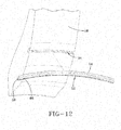
- the air tube 12 is oriented opposite the groove 34 within the lower region of sidewall 16.
- the groove 34 is formed having a sectional geometry complementary to the external geometry of the air tube 26.
- the opening to the groove 34 is enlarged by appropriate tooling (not shown).
- the air tube 26 then inserts into the groove 34 in an orientation in which the enlarged cap 64 is radially inwardmost within the groove and the narrower tube base 66 faces radially outward.
- FIG. 13 shows the fully inserted tube 26 within the sidewall groove.
- FIG. 14 The location of the completed air tube assembly into the lower region of tire sidewall 16 relative to the tire bead 22 is seen in section in FIG. 14, and FIG. 15 shows the same sectional view at a check valve location of the air tube assembly 26.
- the air tube 26 sequentially flattens for one half of the tire revolution and pumps air between the inlet 30 and outlet 32 and thereby into the tire cavity.
- the check valves within bodies 42 are spaced along the air tube 26 and oriented to allow air to flow in direction 36 but preclude back air flow in an opposite direction.
- a bidirectional pumping configuration for the air tube 26 may be deployed.
- the air tube 26 constitutes a 360° loop with the inlet device 30 and outlet device 32 180° opposite to each other.
- Check valve bodies 42 are spaced apart at preferred intervals along the 360° air tube 26.
- the air tube 26 sequentially flattens and unflattens segment by segment. Air is thus pumped bi-directionally along the air tube between the inlet and outlet devices 30, 32 and into the tire cavity.
- FIG. 11 shows yet a third alternative air tube configuration that allows for a uni-directional pumping of air along the air tube during a complete tire revolution.
- the inlet and outlet devices 30, 32 are locate proximally to each other at terminal ends of a 360° air tube loop.
- the check valve bodies 42 are spaced apart along the air tube extent. As the tire rotates in the rotation shown, the air tube 26 sequentially flattens and unflattens. Air is thereby pumped along the air tube 26 in direction 88 between inlet 30 and outlet 32 and then into the tire cavity.
- the subject invention provides an air pumping tube and tire system and method of assembling that is efficient and effective.
- the tire groove 34 is formed to extend into a flexing region of the tire sidewall 16 and the tire 12 is cured.
- the complementary air pumping tube 26, configured to insert into the tire groove, is adapted to accept check valves while in the green or uncured state.
- one or more access shaft(s) 74 are formed in the air pumping tube 26 to provide admittance of one or more check valve device(s) (42, 50) to a check valve seating depth, wherein in the check valve device(s) align with the air passageway 28.
- Plug components 78 of the system substantially fill each access shaft 74 after insertion of the check valve devices.
- Each access shaft 74 is formed by the removal of a slug component 68 from the air maintenance tube and filled subsequently by the insertion of a plug component 78.
- Check valve devices are thereby positioned along the air passageway and directionally allow air to flow in a specified direction but prevent the air from back flowing in an opposite direction.
- the check valves are inserted, and the plug component(s) placed in the air pumping tube in an uncured, green state. Subsequent to the placement and enclosure of the check valves within the air pumping tube by system plug components 78, the air pumping tube having the enclosed check valves is cured.
- the plug components 78, the outer body 42 of each check valve device, and the air pumping tube 26 are composed of compatible materials that bond together as result of the curing procedure. Post cure, the air pumping tube 26 containing the check valves are inserted into the sidewall groove 34 of the cured tire 12.
Abstract
Description
- This invention was made with government support under contract number DE-EE0005447 awarded by the Department of Energy. The government has certain rights in the invention.
- The invention relates generally to air maintenance systems for a tire and, more specifically, to such systems that assemble an air pump apparatus into a tire in order to pump air into the tire as the tire rotates.
- Normal air diffusion reduces tire pressure over time. The natural state of tires is under inflated. Accordingly, drivers must repeatedly act to maintain tire pressures or they will see reduced fuel economy, tire life and reduced vehicle braking and handling performance. Tire pressure monitoring systems have been proposed to warn drivers when tire pressure is significantly low. Such systems, however, remain dependent upon the driver taking remedial action when warned to re-inflate a tire to recommended pressure. It is a desirable, therefore, to incorporate an air maintenance feature within a tire that will maintain a desired level of air pressure within the tire and compensate for any reduction in tire pressure over time without the need for driver intervention.
- The invention relates to an air maintenance tire in accordance with claim 1 and to a method in accordance with claim 9.
- Dependent claims refer to preferred embodiments of the invention.
- In one preferred aspect of the invention, an air pumping tube and tire system and method of assembling is provided in which a tire groove is formed to extend into a flexing region of a tire sidewall and a complementary air pumping tube inserts into the tire groove. In the green, uncured condition, one or more access shaft(s) are formed in the air pumping tube to provide admittance of one or more check valve device(s) to a check valve seating depth, wherein in the check valve device(s) align with the air passageway. A plug component of the system substantially fills each access shaft after insertion of the check valve devices. Each access shaft is formed by the removal of a slug component from the air maintenance tube which is replaced by a shaft-residing plug component.
- In another preferred aspect, the air pumping tube is configured having a mushroom sectional configuration comprising a larger diameter tube cap and an adjoining smaller diameter tube base. The air passageway resides along a mid-region of the air pumping tube at the intersection of the cap and base of the air pumping tube.
- Pursuant to a further aspect, the air passageway is elliptical in sectional configuration and oriented to extend in a longitudinal axial direction between the tube cap and the tube base.
- According to another preferred aspect, the slug component(s) are removed, the check valves inserted, and the plug component(s) placed with the air pumping tube in an uncured condition. Subsequent to placement and enclosure of the check valves within the air pumping tube by system plug components, the air pumping tube is cured. The plug components, the outer body of each check valve device, and the air pumping tube are composed of compatible materials that bond together as result of the curing procedure. Post cure, the air pumping tube containing the check valves are inserted into the sidewall groove of the cured tire.
- "Axial" and "axially" means lines or directions that are parallel to the axis of rotation of the tire.
- "Circumferential" means lines or directions extending along the perimeter of the surface of the annular tread perpendicular to the axial direction.
- "Footprint" means the contact patch or area of contact of the tire tread with a flat surface at zero speed and under normal load and pressure.
- "Lateral" means an axial direction.
- "Peristaltic" means operating by means of wave-like contractions that propel contained matter, such as air, along tubular pathways.
- "Radial" and "radially" means directions radially toward or away from the axis of rotation of the tire.
- The invention will be described by way of example and with reference to the accompanying drawings in which:
-
FIG. 1 is a perspective view of tire with vein tube. -
FIG. 2 is a perspective view of check valve. -
FIG. 3 is a section view of check valve open, allowing air flow. -
FIG. 4 is a section view of check valve closed, blocking air flow. -
FIG. 5 is a perspective view of extruded tubing with teardrop passage. -
FIG. 6 is a perspective view of extruded tubing having a section removed for check valve. -
FIG. 7 is a perspective view of extruded tubing receiving the check valve. -
FIG. 8 is a perspective view of extruded tubing with check valve in place, receiving a plug component. -
FIG. 9 is a plan view of tire with extruded tubing and check valves in a 180° embodiment. -
FIG. 10 is a section Plan view of tire with extruded tubing and check valves in a double 180°embodiment. -
FIG. 11 is a plan view of tire with extruded tubing and check valves in a 360° embodiment. -
FIG. 12 is an enlarged perspective section view of tire with slot for receiving extruded tubing. -
FIG. 13 is an enlarged perspective section view of tire with extruded tubing in place. -
FIG. 14 is an enlarged section view fromFIG. 11 , taken through the extruded tubing. -
FIG. 15 is an enlarged section view fromFIG. 11 , taken at the face of a check valve. - Referring to
FIGS. 1 and5 , a tire and air maintenance pump assembly 10 (forming an air maintenance tire or "AMT") includes atire 12 and a vein pump assembly including avein tube 26. The general operation of a peristaltic pump for use in a tire is described inUS-B-8,113,254 andUS-B-8,042,586 , which are incorporated herein in their entirety by reference. The tire is constructed to provide atread region 14, a pair ofsidewalls opposite bead areas region 14. The tire encloses atire cavity 20. The air maintenance assembly includes anelongate air tube 26 that encloses anair passageway 28 that is preferably generally elliptical in cross-section. Thetube 26 is preferably formed of a resilient, elastomeric flexible material such as plastic or rubber compounds and composites that are capable of withstanding repeated deformation cycles wherein the tube is deformed into a flattened condition subject to external force and, upon removal of such force, returns to an original condition generally circular in cross-section. The tube is of a diameter sufficient to operatively pass a volume of air sufficient for the purpose of maintaining air pressure within thecavity 20. Thetube 26 is shown to follow a 180° semi-circular path in the configuration ofFIG. 1 . However, other configurations, such as 360°annular tube, may be employed without departing from the invention. - The air maintenance vein pump assembly further preferably includes an
inlet device 30 and anoutlet device 32 spaced apart approximately 180° at respective opposite end locations of theair tube 26. Theoutlet device 32 preferably has a T-shaped configuration in which T-forming sleeves connect to an end of thetube 26 and an outlet conduit conducts air from the tube to thetire cavity 20. Theinlet device 30 likewise preferably is of a T-shaped configuration, connecting to an opposite end of thetube 28 and having an inlet conduit which intakes outside air into thetube passageway 28. The pending applications previously identified and incorporated herein provide the details of the outlet and inlet devices. Situated within the inlet and outlet devices are appropriate, commercially available valve mechanisms for controlling air intake into thetube 26 and outlet from the tube into thecavity 20. - As will be appreciated from
FIGS. 1 and12 through 15 , theair tube 26,inlet device 30, and theoutlet device 32 are positioned within an appropriately complementarily configuredchannel 34 within one or both of the tire sidewalls 16, 18. As seen inFIG. 9 , as the tire rotates in the direction of rotation indicated, a footprint is formed against a ground surface (not shown). A compressive force is thus directed into the tire from the footprint and acts to flatten a segment of theair tube 26 andpassageway 28. As the tire rotates further, the air tube and passageway are sequentially flattened and pump air in thedirection 36 shown. Flattening of the tube segment by segment thereby forces air from the inlet alongtube passageway 28, until the pressurized air is directed from the outlet and into the tire cavity. Appropriate valve mechanism at the outlet will vent the air in the event that the tire cavity pressure is at or above the recommended tire pressure. Pumping of air occurs for one-half the revolution of the tire with the 180 degree air tube configuration shown. -
FIG. 10 shows an alternative 360° air tube which functions as described above, with the exception that air is pumped along the air tube indirection 72 for the entire 360° revolution of the tire.FIG. 4 shows a tire with two 180° peristaltic tubes as an alternative embodiment. In theFIG. 4 embodiment, the pump will function in either direction of tire rotation shown by the directional arrows. The two air tubes are each operational in a respective direction of rotation to pump air into the tire cavity. - With reference to
FIGS. 5, 6 and7 , pursuant to the invention a plurality of check valves are provided for assembly into thepassageway 28 of thevein tube 26. The check valve includes a cylindrical valve body, composed of any suitable rigid or semi-rigid material. The body has a rounded forward end rim. An array of outwardly directed retention ribs or flanges are spaced apart along the surface of the valve body, each retention rib angling to the rear of the body. A flexible membrane member, of suitable elastomeric composition, is assembled into a central through passage of the cylindrical valve body. The membrane member includes a cylindrical membrane body captured within the valve body by in turned end flanges of the valve body. The membrane insert further includes a central projecting nose having a slit there through. The nose forms a gate through which pressurized air can flow in a forward direction but which prevents a back flow of air through the check valve in a rearward direction. - Assembly of the check valves into the air tube may be made so as to create a segmented vein air tube. The check valves serve to avoid back flow, control air flow direction, and provide a simplified pump mechanism from compression ratio and pinching force to compression ratio only. The construction of an air pumping tube can be done by segmenting the tube and connecting opposite ends of each air tube segment to a check valve. An alternative assembly may be effected by means of specialized clamping and expansion of tube, insertion of the check valves to desired respective locations within the tube, whereby forming a complete air tube and check valve assembly. The assembly may then be inserted into a groove within the tire sidewall in a post-cure assembly procedure.
US-2014/0110029 shows such an assembly sequence and method. - The subject invention achieves yet a further alternative method of forming a peristaltic air pumping tube having a series of check valves positioned at intervals along the tube. The subject method of check valve placement includes the steps: extruding or molding a unitary tubing with one or more open section(s) or shaft(s) on the tube; inserting check valves after extrusion into each open section(s) or shaft(s) (green tube); closing the open section(s) or shaft(s) after the valves are inside the green tubing; and curing the green tubing to ensure a proper seal between the check valves and the tubing.
- The subject method avoids check valve connection to tubing post-cure; does not require a high deformation of tire sidewall to provide pumping; eliminates back flow; can accept tire/groove dimensional and/or geometrical variation or irregularity; can accept rim dimensional and/or geometrical variation or anomaly; achieves a higher efficiency in pumping than previous air tube construction methods; and eliminates dead-end air volume issues.
- With reference to
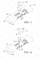
FIGS. 2, 3 and 4 , a checkvalve insert body 42 of preferably generally cylindrical geometry is formed out of suitable elastomeric or rubber composition. Thebody 42 includesend walls bore 48 preferably extending there through along a longitudinal axis. Situated within thebody 42 is avalve chamber 49 dimensioned to receive acheck valve 50. Thecheck valve 50 preferably includes a rearwardlydisposed seating collar 52 seated within thevalve chamber 49 against aninternal shoulder 56. A slottedconical membrane 58 preferably is secured tocollar 52 and tapers inwardly forward into thechamber 49. Themembrane 58 preferably includes peripheral slits spaced about a circumference that allow themembrane 58 to divergently open as shown inFIG. 3 when subjected to air pressure indirection 60; and, upon removal of the air pressure, resume a closed configuration as shown inFIG. 4 bydirectional arrow 62. As used herein, "check valve component" refers to the assembly constituting thecheck valve body 42 containing thecheck valve 50 therein. -
FIGS. 5, 6 ,7 and 8 show an assembly sequence wherebymultiple check valves 50 are assembled into theaxial passageway 28 of the elastomericflexible tube 26. Themultiple check valves 50, each housed within abody 42, occupy spaced apart respective locations within thetube 26 in an orientation which facilitates a flow of pressurized air in a forward direction from theinlet device 30 to the outlet device 32 (FIG. 9 ) but which prevents a back flow of pressurized air in the reverse direction. As seen inFIG. 5 , theperistaltic air tube 26 is formed having a preferably generally mushroom shaped sectional profile formed by a wide tube cap orlobe 64 and a smaller widthunderlying tube base 66. Theair passageway 28 is preferably generally elliptical in section, having a longitudinal axis oriented along a transverse axis of theelongate air tube 28. The air passageway extends longitudinally co-extensive with theair tube 26 at a mid-air tube depth location generally where thecap 64 of thetube 26 intersects thebase 66 of the tube. Thetube 26 is formed of elastomeric material, preferably of rubber or composite rubber materials, by conventional means such as extrusion or molding. Thetube 26 during check valve assembly is in its green (also referred herein as "pre-cured" or "uncured") form. Subsequently, theair tube 26 containing the check valves is cured and inserted into a complementary groove formed within a cured tire. Thetube 26 has a length sufficient to extend an intended path about a lower region of atire sidewall 16. In the path designated byFIG. 9 , thetube 26 follows a curvilinear path of 180°. Alternatively, as seen inFIG. 10 , thetube 26 and correspondinggroove 34 may be formed in a 360° path so as to pump air cont inuously during each entire tire revolution. - Referring to
FIG. 6 , anaccess slug component 68 of thegreen tube 26 is removed after the tube is formed by means of an extrusion or molding. Removal of multiple slug components may be performed if desired, either in sequence or in unison. Theslug component 68 is removed in thedirection 70 and creates a portal 72 andaccess shaft 74 that extend into thecap 64 to a depth encompassing the depth of theair passageway 28 within thetube 26. Location of theaccess shaft 74 along thetube 26 is at a preselected location where placement of a check valve is desired. One or, preferably, multiple slug components 68 (one being shown inFIG. 6 ) are removed from thetube 26, forming a series ofaccess shafts 74 at spaced apart intervals where the location of multiple check valves is desired. Eachslug component 68 removed leaves ashaft 74 that has a depth D sufficient to extend through thetube cap 64 and into thenarrow tube base 66. Eachslug component 68 has a width W and depth D closely complementing a check valve body to be inserted into the shaft vacated by the slug. Theslug component 68 further has a depth sufficient to extend into theair tube 26 to a sufficient depth to reach theair passageway 28. The width and length of eachslug component 68 corresponds to the width and length of theshaft 74 needed for insertion of a check valve device. -
FIG. 7 shows insertion of thecheck valve body 42 into theaccess shaft 74 and downward into a supportivecheck valve seat 76 at a lower terminal end of theshaft 74. Accurate control of the depth D of theslug component 68 places thecheck valve seat 76 and thecheck valve body 42 therein in an aligned location with theair passageway 28 of thetube 26. The length of thecheck valve body 42 preferably correlates with the length L of theslug component 68 such that thebody 42, once inserted down theshaft 74 and into theseat 76, is co-extensive with the segment ofpassageway 28 removed by the removal of theslug component 68.FIG. 8 shows thecheck valve body 42 seated within theseat 76. It will be appreciated that the width and length W and L of thebody 42 fills the void within the lower region of theshaft 74 vacated by theslug component 68. It will further be noted that, when seated, thecheck valve body 42 is located at a depth within theair tube 26 correlating with the depth of theair passageway 28. Theshaft 74 thus extends to a depth at the intersection of theenlarged cap 64 of theair tube 26 and thenarrower base 66 of theair tube body 26. - After inline placement the
check valve body 42 into theair tube 26, aquadrilateral plug component 78 is inserted through the portal 72 and into theshaft 74 of thetube 26, substantially filling the void withinshaft 74 vacated byslug component 68. Theplug component 78 has a width W and length L facilitating a close fit insertion of the plug component into theshaft 74. Theplug component 78 is preferably formed as a generally rectangular quadrilateral body and preferably includes a semi-cylindrical undercut 80 within a bottom plug component surface. The undercut 80 circumscribes thecheck valve body 42 seated within theseat 76, filling the void surrounding thebody 42. Theplug component 78 is preferably formed from green, uncured material composition matching the material composition of theair tube 26 or from a compatible material or composite capable of bonding with the material ofair tube 26. Once theplug component 78 is fully inserted into theshaft 74, theair tube 26 is restored to its original external geometry. - The aforementioned sequence for insertion of a
check valve body 42 into theair tube 26 is repeated either sequentially or in unison for all check valve bodies which are intended for the air tube at their respective locations along theair tube 26. Once insertion of thecheck valve bodies 42 and closinginsert plug components 78 is complete, the green air tube and check valve assembly is complete and ready for curing. When subject to heat in a curing cycle, theelastomeric air tube 26 bonds with theinsert plug components 78 to seal in thecheck valves 42 and re-establish a uniform external geometry along theair tube 26. Thecheck valve bodies 42, composed of material compatible with that of theair tube 26, likewise bonds with the air tube material to fix thebodies 42 at their preferred locations along the air tube. - To assemble the post-cured air tube and check valve assembly into a post-cured tire, as seen in
FIG. 12 , theair tube 12 is oriented opposite thegroove 34 within the lower region ofsidewall 16. Thegroove 34 is formed having a sectional geometry complementary to the external geometry of theair tube 26. The opening to thegroove 34 is enlarged by appropriate tooling (not shown). Theair tube 26 then inserts into thegroove 34 in an orientation in which theenlarged cap 64 is radially inwardmost within the groove and thenarrower tube base 66 faces radially outward.FIG. 13 shows the fully insertedtube 26 within the sidewall groove. - The location of the completed air tube assembly into the lower region of
tire sidewall 16 relative to thetire bead 22 is seen in section inFIG. 14, and FIG. 15 shows the same sectional view at a check valve location of theair tube assembly 26. Operationally, as the tire rotates indirection 36, seen inFIG. 9 , theair tube 26 sequentially flattens for one half of the tire revolution and pumps air between theinlet 30 andoutlet 32 and thereby into the tire cavity. The check valves withinbodies 42 are spaced along theair tube 26 and oriented to allow air to flow indirection 36 but preclude back air flow in an opposite direction. Alternately, as seen inFIG. 10 , a bidirectional pumping configuration for theair tube 26 may be deployed. In the alternative configuration, theair tube 26 constitutes a 360° loop with theinlet device 30 andoutlet device 32 180° opposite to each other. Checkvalve bodies 42 are spaced apart at preferred intervals along the 360°air tube 26. As the tire rotates along a road surface in either aforward direction 82 or areverse direction 84, theair tube 26 sequentially flattens and unflattens segment by segment. Air is thus pumped bi-directionally along the air tube between the inlet andoutlet devices FIG. 11 shows yet a third alternative air tube configuration that allows for a uni-directional pumping of air along the air tube during a complete tire revolution. The inlet andoutlet devices check valve bodies 42 are spaced apart along the air tube extent. As the tire rotates in the rotation shown, theair tube 26 sequentially flattens and unflattens. Air is thereby pumped along theair tube 26 indirection 88 betweeninlet 30 andoutlet 32 and then into the tire cavity. - From the foregoing, it will be appreciated that the subject invention provides an air pumping tube and tire system and method of assembling that is efficient and effective. The
tire groove 34 is formed to extend into a flexing region of thetire sidewall 16 and thetire 12 is cured. The complementaryair pumping tube 26, configured to insert into the tire groove, is adapted to accept check valves while in the green or uncured state. While in the green, uncured condition, one or more access shaft(s) 74 are formed in theair pumping tube 26 to provide admittance of one or more check valve device(s) (42, 50) to a check valve seating depth, wherein in the check valve device(s) align with theair passageway 28.Plug components 78 of the system substantially fill eachaccess shaft 74 after insertion of the check valve devices. Eachaccess shaft 74 is formed by the removal of aslug component 68 from the air maintenance tube and filled subsequently by the insertion of aplug component 78. - Check valve devices are thereby positioned along the air passageway and directionally allow air to flow in a specified direction but prevent the air from back flowing in an opposite direction.
- It will further be noted that the check valves are inserted, and the plug component(s) placed in the air pumping tube in an uncured, green state. Subsequent to the placement and enclosure of the check valves within the air pumping tube by
system plug components 78, the air pumping tube having the enclosed check valves is cured. Theplug components 78, theouter body 42 of each check valve device, and theair pumping tube 26 are composed of compatible materials that bond together as result of the curing procedure. Post cure, theair pumping tube 26 containing the check valves are inserted into thesidewall groove 34 of the curedtire 12.
Claims (15)
- An air maintenance tire comprising:an elongate groove formed to extend into a flexing region of a tire sidewall (16, 18), the groove having a profiled internal geometry;an elongate tube (26) having an internal elongate air passageway (28) and an external geometric shape substantially complementing the groove internal geometry for operably enabling a close receipt of the tube (26) into the groove;the tube (26) having at least one access shaft (74) preferably formed therein extending from an outward surface to a check valve seat (76) positioned at a depth within the tube (26) substantially in line with the air passageway (28);a check valve device (42) configured to insert into the access shaft (74) and to seat within the check valve seat (76) in alignment with the air passageway (28); anda plug component (78) substantially filling the access shaft (74) to a depth of the check valve device (42) whereby occupying the access shaft (74).
- The air maintenance tire claim 1, wherein the access shaft (74) is formed and the check valve device (42) is seated within the tube (26) while the tube (26) is in a green, uncured condition.
- The air maintenance tire of claim 1 or 2, wherein the access shaft (74) is operably formed by a removal of a slug component (68) from the tube (26) with the tube (26) in the green, uncured condition, and, optionally, wherein the plug component (78) is configured to replace the removed slug component (68) within the access shaft (74).
- The air maintenance tire of at least one of the previous claims, wherein the tube (26) operable seats a plurality of the check valve devices (42) through a like plurality of access shafts (74) spaced at preselected intervals along the tube (26).
- The air maintenance tire of at least one of the previous claims, wherein the access shaft (74) is operably dimensioned to closely receive and pass the check valve device (42) to a check valve seat depth, and the plug component (78) to a residency location therein.
- The air maintenance tire at least one of the previous claims, wherein the tube (26) is configured having a mushroom sectional configuration comprising a larger diameter tube cap (64) and an adjoining smaller diameter tube base (66), the air passageway (28) residing substantially at a mid-region of the tube (26) at the intersection of the cap and base of the tube (26), and, optionally, wherein air passageway (28) is substantially elliptical in sectional configuration having a longitudinal axis oriented to extend between the tube cap (64) and the tube base (66).
- The air maintenance tire at least one of the previous claims, wherein the check valve device (42) comprises an outer device body formed of a material composition compatible for bonding with the tube material composition during a curing operation.
- The air maintenance tire at least one of the previous claims, wherein the outer device body houses a membrane device (58) for operably enabling a flow of air through the outer device body in a first direction and for operably disabling a flow of air through the outer device body in a second direction opposite the first direction.
- A method of assembling an air maintenance tire, the method comprising:forming an elongate groove into a flexing region of a tire sidewall (14, 16), the groove having a profiled internal geometry;forming an elongate tube (26) having an internal elongate air passageway (28) and an external geometric shape substantially complementing the groove internal geometry for operably enabling a close receipt of the air pumping tube into the tire groove;forming at least one access shaft (74) preferably within the tube (26) extending from an outward tube surface to a check valve seat (76) positioned at a depth within the tube (26) substantially in line with the air passageway (28);seating a check valve device (42) through the access shaft (74) to engage the check valve seat (76) in an alignment with the air passageway (28); andfilling the access shaft (74) by a plug component (78) to a depth of the check valve device (42) whereby the plug component (78) occupies the access shaft (74).
- The method of assembling an air maintenance tire claim 9, wherein the access shaft (74) is formed and the check valve device (42) seated within the tube (26) while the tube is in a green, uncured condition.
- The method of assembling an air maintenance tire of claim 9 or 10, further comprising removing a slug component (68) from the tube (23) to form the access shaft (74) while the tube (23) is in an uncured condition; and/or wherein the plug component (78) is configured and dimensioned to replace a removed slug component (68) within the access shaft (74).
- The method of assembling an air maintenance tire of at least one of the claims 9 to 11, further comprising seating a plurality of the check valve devices (42) through a like plurality of access shafts (74) spaced at preselected intervals along the tube (23).
- The method of assembling an air maintenance tire of at least one of the claims 9 to 12, further comprising configuring the tube (23) in a mushroom sectional configuration comprising a larger diameter tube cap and an adjoining smaller diameter tube base, the air passageway (28) residing substantially at a mid-region of the tube at the intersection of the cap and base of the tube.
- The method of assembling an air maintenance tire of at least one of the claims 9 to 13, further comprising configuring the air passageway (28) in a substantially elliptical sectional configuration having a longitudinal axis oriented to extend between the tube cap and the tube base.
- The method of assembling an air maintenance tire of at least one of the claims 9 to 14, further comprising curing the tube (23) containing the check valve device (42) and inserting the cured tube into the tire groove.
Applications Claiming Priority (1)
| Application Number | Priority Date | Filing Date | Title |
|---|---|---|---|
| US14/260,590 US9533533B2 (en) | 2014-04-24 | 2014-04-24 | Vein-style air pumping tube and tire system and method of assembly |
Publications (2)
| Publication Number | Publication Date |
|---|---|
| EP2937233A1 true EP2937233A1 (en) | 2015-10-28 |
| EP2937233B1 EP2937233B1 (en) | 2017-02-22 |
Family
ID=53175271
Family Applications (1)
| Application Number | Title | Priority Date | Filing Date |
|---|---|---|---|
| EP15164683.3A Active EP2937233B1 (en) | 2014-04-24 | 2015-04-22 | Vein-style air pumping tube and tire system and method of assembly |
Country Status (5)
| Country | Link |
|---|---|
| US (1) | US9533533B2 (en) |
| EP (1) | EP2937233B1 (en) |
| JP (1) | JP6542020B2 (en) |
| CN (1) | CN105034717B (en) |
| BR (1) | BR102015008468B1 (en) |
Families Citing this family (3)
| Publication number | Priority date | Publication date | Assignee | Title |
|---|---|---|---|---|
| US9421832B2 (en) * | 2013-02-04 | 2016-08-23 | The Goodyear Tire & Rubber Company | Air maintenance tire |
| US9233583B2 (en) * | 2013-12-11 | 2016-01-12 | The Goodyear Tire & Rubber Company | Tire apparatus |
| US10239368B2 (en) * | 2014-12-11 | 2019-03-26 | The Goodyear Tire & Rubber Company | Air maintenance tire and valve assembly |
Citations (5)
| Publication number | Priority date | Publication date | Assignee | Title |
|---|---|---|---|---|
| US8042586B2 (en) | 2009-12-21 | 2011-10-25 | The Goodyear Tire & Rubber Company | Self-inflating tire assembly |
| EP2384912A1 (en) * | 2010-05-07 | 2011-11-09 | The Goodyear Tire & Rubber Company | Self-inflating tire assembly |
| US8113254B2 (en) | 2009-12-21 | 2012-02-14 | The Goodyear Tire & Rubber Company | Self-inflating tire |
| EP2664467A1 (en) * | 2012-05-14 | 2013-11-20 | The Goodyear Tire & Rubber Company | Peristaltic tube air maintenance tire assembly and method |
| US20140110029A1 (en) | 2012-10-24 | 2014-04-24 | Robert Leon Benedict | Vein pump assembly for air maintenance tire |
Family Cites Families (19)
| Publication number | Priority date | Publication date | Assignee | Title |
|---|---|---|---|---|
| US1050886A (en) | 1910-02-23 | 1913-01-21 | Anson B Wetherell | Vehicle-tire. |
| US1134361A (en) | 1912-02-13 | 1915-04-06 | Anson B Wetherell | Self-filling tire. |
| US1682922A (en) | 1924-07-23 | 1928-09-04 | Charles W Mckone | Rubber-tire-bead construction |
| GB1086512A (en) | 1964-02-24 | 1967-10-11 | Ronald Leslie Sheppard | Improvements in or relating to pneumatic tyres |
| US3833041A (en) | 1973-10-11 | 1974-09-03 | Aerojet General Co | Tire inflator |
| DE3433318A1 (en) | 1984-09-11 | 1986-03-20 | Mousiol, Hans, 6000 Frankfurt | Method for inflating pneumatic tyres and pneumatic tyre for the method |
| IT209132Z2 (en) | 1986-03-04 | 1988-09-12 | Bridgeport Brass Spa | VALVE IMPROVEMENTS FOR TUBELESS TIRES. |
| FR2618102B1 (en) | 1987-07-15 | 1990-02-16 | Michelin & Cie | INFLATION OF A ROTATING TIRE |
| RU2106978C1 (en) | 1995-02-15 | 1998-03-20 | Леонид Михайлович Раткевич | Pneumatic tyre with automatic inflating device |
| SK285543B6 (en) | 2001-12-11 | 2007-03-01 | Franti�Ek Hrabal | Device for monitoring, maintenance and adjustment of pressure in a tyre |
| DE10335244A1 (en) | 2003-08-01 | 2005-03-10 | Bayerische Motoren Werke Ag | Device for air filling a rotating pneumatic tire |
| CZ303718B6 (en) | 2006-05-23 | 2013-04-03 | Sithold S.R.O. | Retentivity component for adjusting pneumatic tyre pressure and process for producing thereof |
| US8327897B2 (en) | 2008-06-03 | 2012-12-11 | David A Firestone | Automatic tire sealing and inflating system |
| SE532584C2 (en) | 2008-07-15 | 2010-02-23 | Jan Folke Wallenius | Vehicle tires with a valve assembly |
| US8186402B2 (en) | 2009-03-24 | 2012-05-29 | Pressure Sentinel, Inc | Device for automatically maintaining tire pressure |
| US8534335B2 (en) | 2010-09-27 | 2013-09-17 | The Goodyear Tire & Rubber Company | Distributed pump self-inflating tire assembly |
| US8695661B2 (en) * | 2011-07-15 | 2014-04-15 | The Goodyear Tire & Rubber Company | Air maintenance pumping tube and tire assembly |
| US8960249B2 (en) * | 2012-10-15 | 2015-02-24 | The Goodyear Tire & Rubber Company | Self-inflating tire |
| US9199518B2 (en) * | 2012-10-24 | 2015-12-01 | The Goodyear Tire & Rubber Company | Method of assemblying a segmented vein air pump in a tire |
-
2014
- 2014-04-24 US US14/260,590 patent/US9533533B2/en active Active
-
2015
- 2015-04-15 BR BR102015008468-4A patent/BR102015008468B1/en active IP Right Grant
- 2015-04-20 JP JP2015085627A patent/JP6542020B2/en active Active
- 2015-04-22 EP EP15164683.3A patent/EP2937233B1/en active Active
- 2015-04-24 CN CN201510199034.2A patent/CN105034717B/en active Active
Patent Citations (5)
| Publication number | Priority date | Publication date | Assignee | Title |
|---|---|---|---|---|
| US8042586B2 (en) | 2009-12-21 | 2011-10-25 | The Goodyear Tire & Rubber Company | Self-inflating tire assembly |
| US8113254B2 (en) | 2009-12-21 | 2012-02-14 | The Goodyear Tire & Rubber Company | Self-inflating tire |
| EP2384912A1 (en) * | 2010-05-07 | 2011-11-09 | The Goodyear Tire & Rubber Company | Self-inflating tire assembly |
| EP2664467A1 (en) * | 2012-05-14 | 2013-11-20 | The Goodyear Tire & Rubber Company | Peristaltic tube air maintenance tire assembly and method |
| US20140110029A1 (en) | 2012-10-24 | 2014-04-24 | Robert Leon Benedict | Vein pump assembly for air maintenance tire |
Also Published As
| Publication number | Publication date |
|---|---|
| BR102015008468A2 (en) | 2016-04-26 |
| BR102015008468B1 (en) | 2021-03-30 |
| EP2937233B1 (en) | 2017-02-22 |
| US20150306924A1 (en) | 2015-10-29 |
| US9533533B2 (en) | 2017-01-03 |
| CN105034717B (en) | 2017-05-03 |
| CN105034717A (en) | 2015-11-11 |
| JP6542020B2 (en) | 2019-07-10 |
| JP2015209204A (en) | 2015-11-24 |
Similar Documents
| Publication | Publication Date | Title |
|---|---|---|
| EP2578420B1 (en) | Tire comprising a tube assembly and method of assembling an elongate air tube within a tire | |
| EP2455239B1 (en) | In-line pumping assembly for self-inflating tire | |
| JP6215650B2 (en) | Vine pump assembly for air maintenance tires | |
| US9199518B2 (en) | Method of assemblying a segmented vein air pump in a tire | |
| EP2565061B1 (en) | Self-inflating tire and pressure regulator device | |
| US9669671B2 (en) | Vein pump assembly for air maintenance tire | |
| EP2565059A2 (en) | Pneumatic tire | |
| EP2543524A1 (en) | Air maintenance pumping assembly and tire | |
| EP2546083A1 (en) | Air maintenance pumping tube and tire assembly | |
| EP2937233B1 (en) | Vein-style air pumping tube and tire system and method of assembly | |
| US9056435B2 (en) | Securing to a pneumatic tire | |
| EP2883718B1 (en) | Self-inflating tire with hybrid pump | |
| JP2015034005A (en) | Valve assembly for air maintenance tire | |
| EP2732989A1 (en) | Pneumatic tire | |
| EP2607109A2 (en) | Tire comprising a connector assembly and method of manufacturing | |
| EP2455240B1 (en) | Method of manufacturing a self-inflating tire | |
| EP2724874B1 (en) | Self-inflating tire and assembling method | |
| EP3031633B1 (en) | Air maintenance tire and valve assembly | |
| EP2987658A1 (en) | Air maintenance tire and method of manufacturing | |
| EP2607108A2 (en) | Tire and method of forming an air passageway in a tire |
Legal Events
| Date | Code | Title | Description |
|---|---|---|---|
| PUAI | Public reference made under article 153(3) epc to a published international application that has entered the european phase |
Free format text: ORIGINAL CODE: 0009012 |
|
| AK | Designated contracting states |
Kind code of ref document: A1 Designated state(s): AL AT BE BG CH CY CZ DE DK EE ES FI FR GB GR HR HU IE IS IT LI LT LU LV MC MK MT NL NO PL PT RO RS SE SI SK SM TR |
|
| AX | Request for extension of the european patent |
Extension state: BA ME |
|
| 17P | Request for examination filed |
Effective date: 20160428 |
|
| RBV | Designated contracting states (corrected) |
Designated state(s): AL AT BE BG CH CY CZ DE DK EE ES FI FR GB GR HR HU IE IS IT LI LT LU LV MC MK MT NL NO PL PT RO RS SE SI SK SM TR |
|
| GRAP | Despatch of communication of intention to grant a patent |
Free format text: ORIGINAL CODE: EPIDOSNIGR1 |
|
| RIC1 | Information provided on ipc code assigned before grant |
Ipc: B60C 23/12 20060101AFI20160812BHEP |
|
| INTG | Intention to grant announced |
Effective date: 20160921 |
|
| GRAS | Grant fee paid |
Free format text: ORIGINAL CODE: EPIDOSNIGR3 |
|
| GRAA | (expected) grant |
Free format text: ORIGINAL CODE: 0009210 |
|
| AK | Designated contracting states |
Kind code of ref document: B1 Designated state(s): AL AT BE BG CH CY CZ DE DK EE ES FI FR GB GR HR HU IE IS IT LI LT LU LV MC MK MT NL NO PL PT RO RS SE SI SK SM TR |
|
| REG | Reference to a national code |
Ref country code: GB Ref legal event code: FG4D |
|
| REG | Reference to a national code |
Ref country code: CH Ref legal event code: EP |
|
| REG | Reference to a national code |
Ref country code: AT Ref legal event code: REF Ref document number: 868985 Country of ref document: AT Kind code of ref document: T Effective date: 20170315 |
|
| REG | Reference to a national code |
Ref country code: IE Ref legal event code: FG4D Ref country code: FR Ref legal event code: PLFP Year of fee payment: 3 |
|
| REG | Reference to a national code |
Ref country code: DE Ref legal event code: R096 Ref document number: 602015001534 Country of ref document: DE |
|
| REG | Reference to a national code |
Ref country code: LT Ref legal event code: MG4D |
|
| REG | Reference to a national code |
Ref country code: NL Ref legal event code: MP Effective date: 20170222 |
|
| REG | Reference to a national code |
Ref country code: AT Ref legal event code: MK05 Ref document number: 868985 Country of ref document: AT Kind code of ref document: T Effective date: 20170222 |
|
| PG25 | Lapsed in a contracting state [announced via postgrant information from national office to epo] |
Ref country code: HR Free format text: LAPSE BECAUSE OF FAILURE TO SUBMIT A TRANSLATION OF THE DESCRIPTION OR TO PAY THE FEE WITHIN THE PRESCRIBED TIME-LIMIT Effective date: 20170222 Ref country code: FI Free format text: LAPSE BECAUSE OF FAILURE TO SUBMIT A TRANSLATION OF THE DESCRIPTION OR TO PAY THE FEE WITHIN THE PRESCRIBED TIME-LIMIT Effective date: 20170222 Ref country code: GR Free format text: LAPSE BECAUSE OF FAILURE TO SUBMIT A TRANSLATION OF THE DESCRIPTION OR TO PAY THE FEE WITHIN THE PRESCRIBED TIME-LIMIT Effective date: 20170523 Ref country code: NO Free format text: LAPSE BECAUSE OF FAILURE TO SUBMIT A TRANSLATION OF THE DESCRIPTION OR TO PAY THE FEE WITHIN THE PRESCRIBED TIME-LIMIT Effective date: 20170522 Ref country code: LT Free format text: LAPSE BECAUSE OF FAILURE TO SUBMIT A TRANSLATION OF THE DESCRIPTION OR TO PAY THE FEE WITHIN THE PRESCRIBED TIME-LIMIT Effective date: 20170222 |
|
| PG25 | Lapsed in a contracting state [announced via postgrant information from national office to epo] |
Ref country code: ES Free format text: LAPSE BECAUSE OF FAILURE TO SUBMIT A TRANSLATION OF THE DESCRIPTION OR TO PAY THE FEE WITHIN THE PRESCRIBED TIME-LIMIT Effective date: 20170222 Ref country code: SE Free format text: LAPSE BECAUSE OF FAILURE TO SUBMIT A TRANSLATION OF THE DESCRIPTION OR TO PAY THE FEE WITHIN THE PRESCRIBED TIME-LIMIT Effective date: 20170222 Ref country code: AT Free format text: LAPSE BECAUSE OF FAILURE TO SUBMIT A TRANSLATION OF THE DESCRIPTION OR TO PAY THE FEE WITHIN THE PRESCRIBED TIME-LIMIT Effective date: 20170222 Ref country code: RS Free format text: LAPSE BECAUSE OF FAILURE TO SUBMIT A TRANSLATION OF THE DESCRIPTION OR TO PAY THE FEE WITHIN THE PRESCRIBED TIME-LIMIT Effective date: 20170222 Ref country code: NL Free format text: LAPSE BECAUSE OF NON-PAYMENT OF DUE FEES Effective date: 20170222 Ref country code: PT Free format text: LAPSE BECAUSE OF FAILURE TO SUBMIT A TRANSLATION OF THE DESCRIPTION OR TO PAY THE FEE WITHIN THE PRESCRIBED TIME-LIMIT Effective date: 20170622 Ref country code: BG Free format text: LAPSE BECAUSE OF FAILURE TO SUBMIT A TRANSLATION OF THE DESCRIPTION OR TO PAY THE FEE WITHIN THE PRESCRIBED TIME-LIMIT Effective date: 20170522 Ref country code: LV Free format text: LAPSE BECAUSE OF FAILURE TO SUBMIT A TRANSLATION OF THE DESCRIPTION OR TO PAY THE FEE WITHIN THE PRESCRIBED TIME-LIMIT Effective date: 20170222 |
|
| PG25 | Lapsed in a contracting state [announced via postgrant information from national office to epo] |
Ref country code: EE Free format text: LAPSE BECAUSE OF FAILURE TO SUBMIT A TRANSLATION OF THE DESCRIPTION OR TO PAY THE FEE WITHIN THE PRESCRIBED TIME-LIMIT Effective date: 20170222 Ref country code: RO Free format text: LAPSE BECAUSE OF FAILURE TO SUBMIT A TRANSLATION OF THE DESCRIPTION OR TO PAY THE FEE WITHIN THE PRESCRIBED TIME-LIMIT Effective date: 20170222 Ref country code: SK Free format text: LAPSE BECAUSE OF FAILURE TO SUBMIT A TRANSLATION OF THE DESCRIPTION OR TO PAY THE FEE WITHIN THE PRESCRIBED TIME-LIMIT Effective date: 20170222 Ref country code: CZ Free format text: LAPSE BECAUSE OF FAILURE TO SUBMIT A TRANSLATION OF THE DESCRIPTION OR TO PAY THE FEE WITHIN THE PRESCRIBED TIME-LIMIT Effective date: 20170222 |
|
| REG | Reference to a national code |
Ref country code: DE Ref legal event code: R097 Ref document number: 602015001534 Country of ref document: DE |
|
| PG25 | Lapsed in a contracting state [announced via postgrant information from national office to epo] |
Ref country code: SM Free format text: LAPSE BECAUSE OF FAILURE TO SUBMIT A TRANSLATION OF THE DESCRIPTION OR TO PAY THE FEE WITHIN THE PRESCRIBED TIME-LIMIT Effective date: 20170222 Ref country code: PL Free format text: LAPSE BECAUSE OF FAILURE TO SUBMIT A TRANSLATION OF THE DESCRIPTION OR TO PAY THE FEE WITHIN THE PRESCRIBED TIME-LIMIT Effective date: 20170222 Ref country code: DK Free format text: LAPSE BECAUSE OF FAILURE TO SUBMIT A TRANSLATION OF THE DESCRIPTION OR TO PAY THE FEE WITHIN THE PRESCRIBED TIME-LIMIT Effective date: 20170222 |
|
| PLBE | No opposition filed within time limit |
Free format text: ORIGINAL CODE: 0009261 |
|
| STAA | Information on the status of an ep patent application or granted ep patent |
Free format text: STATUS: NO OPPOSITION FILED WITHIN TIME LIMIT |
|
| REG | Reference to a national code |
Ref country code: IE Ref legal event code: MM4A |
|
| 26N | No opposition filed |
Effective date: 20171123 |
|
| PG25 | Lapsed in a contracting state [announced via postgrant information from national office to epo] |
Ref country code: MC Free format text: LAPSE BECAUSE OF FAILURE TO SUBMIT A TRANSLATION OF THE DESCRIPTION OR TO PAY THE FEE WITHIN THE PRESCRIBED TIME-LIMIT Effective date: 20170222 |
|
| PG25 | Lapsed in a contracting state [announced via postgrant information from national office to epo] |
Ref country code: LU Free format text: LAPSE BECAUSE OF NON-PAYMENT OF DUE FEES Effective date: 20170422 Ref country code: SI Free format text: LAPSE BECAUSE OF FAILURE TO SUBMIT A TRANSLATION OF THE DESCRIPTION OR TO PAY THE FEE WITHIN THE PRESCRIBED TIME-LIMIT Effective date: 20170222 |
|
| REG | Reference to a national code |
Ref country code: BE Ref legal event code: MM Effective date: 20170430 |
|
| REG | Reference to a national code |
Ref country code: FR Ref legal event code: PLFP Year of fee payment: 4 |
|
| PG25 | Lapsed in a contracting state [announced via postgrant information from national office to epo] |
Ref country code: IE Free format text: LAPSE BECAUSE OF NON-PAYMENT OF DUE FEES Effective date: 20170422 |
|
| PG25 | Lapsed in a contracting state [announced via postgrant information from national office to epo] |
Ref country code: BE Free format text: LAPSE BECAUSE OF NON-PAYMENT OF DUE FEES Effective date: 20170430 |
|
| PG25 | Lapsed in a contracting state [announced via postgrant information from national office to epo] |
Ref country code: MT Free format text: LAPSE BECAUSE OF NON-PAYMENT OF DUE FEES Effective date: 20170422 |
|
| REG | Reference to a national code |
Ref country code: CH Ref legal event code: PL |
|
| PG25 | Lapsed in a contracting state [announced via postgrant information from national office to epo] |
Ref country code: CH Free format text: LAPSE BECAUSE OF NON-PAYMENT OF DUE FEES Effective date: 20180430 Ref country code: LI Free format text: LAPSE BECAUSE OF NON-PAYMENT OF DUE FEES Effective date: 20180430 |
|
| PG25 | Lapsed in a contracting state [announced via postgrant information from national office to epo] |
Ref country code: HU Free format text: LAPSE BECAUSE OF FAILURE TO SUBMIT A TRANSLATION OF THE DESCRIPTION OR TO PAY THE FEE WITHIN THE PRESCRIBED TIME-LIMIT; INVALID AB INITIO Effective date: 20150422 |
|
| PG25 | Lapsed in a contracting state [announced via postgrant information from national office to epo] |
Ref country code: CY Free format text: LAPSE BECAUSE OF FAILURE TO SUBMIT A TRANSLATION OF THE DESCRIPTION OR TO PAY THE FEE WITHIN THE PRESCRIBED TIME-LIMIT Effective date: 20170222 |
|
| PG25 | Lapsed in a contracting state [announced via postgrant information from national office to epo] |
Ref country code: MK Free format text: LAPSE BECAUSE OF FAILURE TO SUBMIT A TRANSLATION OF THE DESCRIPTION OR TO PAY THE FEE WITHIN THE PRESCRIBED TIME-LIMIT Effective date: 20170222 |
|
| GBPC | Gb: european patent ceased through non-payment of renewal fee |
Effective date: 20190422 |
|
| PG25 | Lapsed in a contracting state [announced via postgrant information from national office to epo] |
Ref country code: GB Free format text: LAPSE BECAUSE OF NON-PAYMENT OF DUE FEES Effective date: 20190422 |
|
| PG25 | Lapsed in a contracting state [announced via postgrant information from national office to epo] |
Ref country code: TR Free format text: LAPSE BECAUSE OF FAILURE TO SUBMIT A TRANSLATION OF THE DESCRIPTION OR TO PAY THE FEE WITHIN THE PRESCRIBED TIME-LIMIT Effective date: 20170222 |
|
| PG25 | Lapsed in a contracting state [announced via postgrant information from national office to epo] |
Ref country code: AL Free format text: LAPSE BECAUSE OF FAILURE TO SUBMIT A TRANSLATION OF THE DESCRIPTION OR TO PAY THE FEE WITHIN THE PRESCRIBED TIME-LIMIT Effective date: 20170222 Ref country code: IS Free format text: LAPSE BECAUSE OF FAILURE TO SUBMIT A TRANSLATION OF THE DESCRIPTION OR TO PAY THE FEE WITHIN THE PRESCRIBED TIME-LIMIT Effective date: 20170622 |
|
| PGFP | Annual fee paid to national office [announced via postgrant information from national office to epo] |
Ref country code: FR Payment date: 20230309 Year of fee payment: 9 |
|
| PGFP | Annual fee paid to national office [announced via postgrant information from national office to epo] |
Ref country code: IT Payment date: 20230310 Year of fee payment: 9 |
|
| PGFP | Annual fee paid to national office [announced via postgrant information from national office to epo] |
Ref country code: DE Payment date: 20230307 Year of fee payment: 9 |