EP2935060B1 - Dispositif et procédé permettant de faire tourner des articles plats - Google Patents
Dispositif et procédé permettant de faire tourner des articles plats Download PDFInfo
- Publication number
- EP2935060B1 EP2935060B1 EP13805870.6A EP13805870A EP2935060B1 EP 2935060 B1 EP2935060 B1 EP 2935060B1 EP 13805870 A EP13805870 A EP 13805870A EP 2935060 B1 EP2935060 B1 EP 2935060B1
- Authority
- EP
- European Patent Office
- Prior art keywords
- transport
- goods
- rotation
- turning
- turning device
- Prior art date
- Legal status (The legal status is an assumption and is not a legal conclusion. Google has not performed a legal analysis and makes no representation as to the accuracy of the status listed.)
- Active
Links
- 238000000034 method Methods 0.000 title claims description 31
- 230000003287 optical effect Effects 0.000 claims description 2
- 230000032258 transport Effects 0.000 description 131
- 239000000463 material Substances 0.000 description 52
- 230000008569 process Effects 0.000 description 14
- 208000012886 Vertigo Diseases 0.000 description 6
- 239000011111 cardboard Substances 0.000 description 6
- 230000003068 static effect Effects 0.000 description 3
- 230000001133 acceleration Effects 0.000 description 2
- 239000000123 paper Substances 0.000 description 2
- 239000011087 paperboard Substances 0.000 description 2
- 238000011144 upstream manufacturing Methods 0.000 description 2
- 230000015572 biosynthetic process Effects 0.000 description 1
- 230000003247 decreasing effect Effects 0.000 description 1
- 230000001934 delay Effects 0.000 description 1
- 230000001419 dependent effect Effects 0.000 description 1
- 238000006073 displacement reaction Methods 0.000 description 1
- 230000005484 gravity Effects 0.000 description 1
- 239000002985 plastic film Substances 0.000 description 1
- 229920006255 plastic film Polymers 0.000 description 1
- 230000009467 reduction Effects 0.000 description 1
- 230000000284 resting effect Effects 0.000 description 1
- 230000007704 transition Effects 0.000 description 1
Images


Classifications
-
- B—PERFORMING OPERATIONS; TRANSPORTING
- B65—CONVEYING; PACKING; STORING; HANDLING THIN OR FILAMENTARY MATERIAL
- B65H—HANDLING THIN OR FILAMENTARY MATERIAL, e.g. SHEETS, WEBS, CABLES
- B65H5/00—Feeding articles separated from piles; Feeding articles to machines
- B65H5/02—Feeding articles separated from piles; Feeding articles to machines by belts or chains, e.g. between belts or chains
- B65H5/021—Feeding articles separated from piles; Feeding articles to machines by belts or chains, e.g. between belts or chains by belts
- B65H5/025—Feeding articles separated from piles; Feeding articles to machines by belts or chains, e.g. between belts or chains by belts between belts and rotary means, e.g. rollers, drums, cylinders or balls, forming a transport nip
-
- B—PERFORMING OPERATIONS; TRANSPORTING
- B65—CONVEYING; PACKING; STORING; HANDLING THIN OR FILAMENTARY MATERIAL
- B65H—HANDLING THIN OR FILAMENTARY MATERIAL, e.g. SHEETS, WEBS, CABLES
- B65H5/00—Feeding articles separated from piles; Feeding articles to machines
- B65H5/06—Feeding articles separated from piles; Feeding articles to machines by rollers or balls, e.g. between rollers
- B65H5/062—Feeding articles separated from piles; Feeding articles to machines by rollers or balls, e.g. between rollers between rollers or balls
-
- B—PERFORMING OPERATIONS; TRANSPORTING
- B65—CONVEYING; PACKING; STORING; HANDLING THIN OR FILAMENTARY MATERIAL
- B65H—HANDLING THIN OR FILAMENTARY MATERIAL, e.g. SHEETS, WEBS, CABLES
- B65H5/00—Feeding articles separated from piles; Feeding articles to machines
- B65H5/22—Feeding articles separated from piles; Feeding articles to machines by air-blast or suction device
- B65H5/222—Feeding articles separated from piles; Feeding articles to machines by air-blast or suction device by suction devices
- B65H5/224—Feeding articles separated from piles; Feeding articles to machines by air-blast or suction device by suction devices by suction belts
-
- B—PERFORMING OPERATIONS; TRANSPORTING
- B65—CONVEYING; PACKING; STORING; HANDLING THIN OR FILAMENTARY MATERIAL
- B65H—HANDLING THIN OR FILAMENTARY MATERIAL, e.g. SHEETS, WEBS, CABLES
- B65H9/00—Registering, e.g. orientating, articles; Devices therefor
- B65H9/002—Registering, e.g. orientating, articles; Devices therefor changing orientation of sheet by only controlling movement of the forwarding means, i.e. without the use of stop or register wall
-
- B—PERFORMING OPERATIONS; TRANSPORTING
- B65—CONVEYING; PACKING; STORING; HANDLING THIN OR FILAMENTARY MATERIAL
- B65H—HANDLING THIN OR FILAMENTARY MATERIAL, e.g. SHEETS, WEBS, CABLES
- B65H2301/00—Handling processes for sheets or webs
- B65H2301/30—Orientation, displacement, position of the handled material
- B65H2301/33—Modifying, selecting, changing orientation
- B65H2301/332—Turning, overturning
- B65H2301/3321—Turning, overturning kinetic therefor
- B65H2301/33216—Turning, overturning kinetic therefor about an axis perpendicular to the direction of displacement and to the surface of material
-
- B—PERFORMING OPERATIONS; TRANSPORTING
- B65—CONVEYING; PACKING; STORING; HANDLING THIN OR FILAMENTARY MATERIAL
- B65H—HANDLING THIN OR FILAMENTARY MATERIAL, e.g. SHEETS, WEBS, CABLES
- B65H2301/00—Handling processes for sheets or webs
- B65H2301/30—Orientation, displacement, position of the handled material
- B65H2301/33—Modifying, selecting, changing orientation
- B65H2301/332—Turning, overturning
- B65H2301/3322—Turning, overturning according to a determined angle
- B65H2301/33222—90°
Definitions
- the invention relates to a device for rotating flat goods moving in a transport direction according to the preamble of claim 1 and to a corresponding method according to the preamble of claim 13.
- Devices of the generic type are used for example in paper processing machines, such. As inserters, printers or copiers used.
- the material to be turned may be, for example, individual sheets or sheets or a sheet stack of at least two sheets.
- generic devices can also be used for turning other flat goods, such. For example, for turning plastic films, cardboard sheets or the like or for turning of connected or stapled sheets in the form of catalogs, brochures, booklets or similar products.
- a device for rotating rectangular cardboard sheets by 90 ° is known, which are stored in a predetermined orientation for further processing in a container.
- This known device comprises a conveyor belt which is moved at a first speed in a transport direction in order to move the cardboard sheets to be rotated by an angle of 90 ° in a first orientation to a rotating device.
- the rotator includes a first nip and a second nip, wherein a first portion of the paperboard sheet to be rotated is brought into engagement with the first nip and a second portion of the paperboard sheet is engaged with the second nip.
- the first gap in this case has a first pressure roller, which defines a gap between its outer circumference and the conveyor belt, in which the first section of the cardboard sheet is brought into engagement.
- the second gap is defined by a pair of rotary rollers with a driven rotary roller and a pressure roller between the outer periphery engages the second portion of the cardboard sheet to be rotated.
- the driven roller of the rotary roller pair is driven to rotate the cardboard sheet at a speed which is different from the transport speed of the transport path.
- a device for rotating moving flat goods in the form of sheets or stacks of sheets wherein in a first rotating means, the goods are first rotated by a first rotation angle and then rotated in a second rotation means by a second rotation angle.
- the first rotary device and the second rotary device are arranged one behind the other in a transport direction of the goods and between the two rotary devices a transport device is provided, which linearly moves the material rotated in the first rotary device through the first rotational angle in the transport direction and for further rotation to the second rotary device passes.
- the DE 10 2008 050 524 A1 describes a device for aligning flat goods in the form of banknotes, the device comprising first and second transport elements for transporting the goods and at least one first and one second rotating transport element.
- the first rotating transport element generates on the goods an obliquely to the lying in the transport plane center axis of the transport path driving force.
- the second rotating transport element generates on the goods a driving force acting parallel to the central axis.
- the device further comprises a pressure unit, which exerts a pressure force on the goods in a pressure position.
- the EP 0 814 041 B1 discloses a method for rotating sheets from a first orientation to a perpendicular orientation and a sheet stacking apparatus in which sheets to be stacked are rotated according to the method from a first orientation to a perpendicular orientation.
- the sheets to be rotated are smoothly moved between an upstream and a downstream position during rotation, and differentially moved in an intermediate phase of movement without changing the speed component in the sheet travel direction.
- the sheet In the intermediate phase of movement (rotational phase), the sheet is moved with a speed-time profile containing a first speed function in which the movement speed is temporarily increased by a predetermined amount and a second speed function in which the movement speed is temporarily the same predetermined Amount and at the same time is temporarily reduced, thereby rotating the arc by a rotation angle, wherein the amount of the rotation angle is determined by the duration of the increased or reduced movement speed.
- a lateral displacement which is determined by appropriately selecting the timing at which the rotation of the sheet is initiated with respect to the arrival of the sheet at a fixed reference point.
- the rotation of the sheet takes place by means of a rotating device, which has transversely to the sheet running direction spaced roller pairs, which are driven by a stepper motor to produce the predetermined speed-time profiles of the roller pairs.
- the division of the entire turning process into two or more sub-steps makes it possible, with very high cycle power or decreasing cycle time, that more time and more space is available for the individual turning operations.
- the clock power can be increased in a division of the entire turning operation in two or more sub-steps, because already the following good can be introduced into the first rotating device, while the previous good is still in the turning process in a downstream rotary device.
- a conveyor device for rotating sheet stacks moving along a turning path comprising a turning conveyor consisting of two conveyors running side by side and at different speeds, a first trajectory having a conveyor drivable and revolving at a first speed and the second trajectory In the conveying direction one behind the other at least two circulating conveyor, which are driven at a different speed from the first speed. Due to the different speeds of the first web and the multiple conveyors The second web is rotated by the sheet stack resting on the two webs by a predetermined angle of rotation, which depends on the difference between the speeds of the first web and the second web.
- a respective position detector for detecting the instantaneous angular position of the transported stack of sheets is arranged.
- the signal detected by the position detectors which represents a measure of the angular position of the sheet stacks at the respective position of the position detector, is used to control the drives of the first and the second path to possibly occurring positional deviations by adjusting the speed difference between the conveyor of the first path and the corresponding conveyor of the second track.
- an apparatus for rotating the orientation of mailpieces from a first orientation to a second orientation which are moved along a transport path.
- the device comprises a plurality of roller pairs arranged one behind the other in the transport direction, which are arranged in the transverse direction to the transport direction at a distance from each other.
- the transversely spaced pairs of rollers are driven to rotate the mail pieces at different speeds, with the mail piece in each of the pairs of rollers being rotated by a predetermined angle of rotation, which depends on the differential speed of the pairs of rollers, which may be different for each pair of rollers.
- the arrangement of the pairs of rollers comprises at the beginning and at the end in each case a pair of rollers, with which the mail piece is not rotated but linearly moved in the transport direction.
- the postal item is moved further in the transporting direction.
- the lateral distance from corresponding rollers of a pair of rollers can be adjusted to produce a defined rotation of the mailpiece in the respective pair of rollers and to adjust an offset of the mail piece.
- the known rotating devices and methods in which the entire turning process is carried out in at least two sub-steps prove to be disadvantageous because the distance of the fulcrums in the lateral direction (transport direction) is fixed and can not be adjusted. This is particularly disadvantageous if goods, for example sheets, with different formats are to be processed with the same turning device.
- the object of the invention is to provide a device and a method for turning flat goods moving in a transport direction, with which goods of different formats can be processed with as high a throughput as possible and as trouble-free as possible.
- the goods to be turned should be treated gently, so that it can not come to damage the goods during the turning process.
- the rotation of a product moving in a transport direction is divided by the predetermined total rotation angle into two or more substeps, each increment of rotation taking place in a rotating device provided therefor.
- the device according to the invention contains at least one first rotary device and one second rotary device, which are arranged one behind the other in the transport direction and at a distance from one another.
- the material is rotated by a first angle of rotation and in the second rotary device by a second angle of rotation and optionally in further, in the transport direction successively arranged rotating means by further rotation angle until the total rotation angle is reached.
- the turning operation in the first rotating means and the second rotating means is by one between these two Rotary devices arranged transport decoupled.
- the transport device arranged between the first rotary device and the second rotary device moves the material rotated in the first rotary device linearly (ie without rotation) in the transport direction and then transfers the material to the second rotary device, in which it continues by the second rotational angle is turned.
- the pitch of the fulcrums can be selected independently of the format of the crop. Furthermore, the beginning of the turning operation in the first and the second rotating device can be arbitrarily selected and adapted for example to the format of the Guts or the desired position and orientation of the Guts after the turning operation. As a result, for example, a lateral offset of the material in the lateral direction (transverse to the transport direction) can be set or compensated.
- the entire turning process is preferably split into two sub-steps, so that the sum of the first turning angle in the first turning operation and the second turning angle in the second turning operation yields the desired overall turning angle.
- the desired total rotation angle is, for example, 90 °, when the material to be rotated is to be rotated from a first orientation in portrait orientation to a second orientation in landscape orientation (or vice versa).
- the inventive method is not limited to the rotation of goods by a total rotation angle of 90 °. Rather, any desired angle of rotation can be achieved with the method according to the invention.
- the rotation angle (first angle of rotation, second angle of rotation and optionally further angles of rotation in further directions of rotation of the device according to the invention) taking place in the individual rotary steps depends on a rotation angle Speed difference of rotating means in the first and second rotating means or optionally further existing rotating means from.
- the rotating means of the rotating means comprise a first pair of rotary rollers and a second pair of rotary rollers, wherein the first pair of rotary rollers and the second pair of rotary rollers are arranged at a lateral distance to each other in the transverse direction to the transport direction and for rotating the Guts at different rotational speeds of a motor be driven rotating.
- the difference in the rotational speeds of the pairs of pairs of rotary rollers located at a lateral distance determines the angle of rotation in the respective rotary device (first rotary angle in the first rotary device and second rotational angle in the second rotary device).
- the lateral distance of the corresponding pair of rotary roller pairs of the first rotary device or the second rotary device is adjustable.
- the lateral spacing of the corresponding pair of rotary roller pairs can be adapted to the format of the item, for example. This further improves the use of the device according to the invention for turning different goods with different formats and sizes.
- the transport device arranged between the first rotating device and the second rotating device is preferably switchable between a first position and a second position, wherein the transport device engages a good in the first position and in the second position the goods is out of engagement with the transport device.
- the material rotated in the first rotating means by the predetermined first turning angle is taken over by the conveying means by bringing the conveying means into its first position in which it engages the goods as soon as the crop in the first rotating means is completely rotated by the predetermined first turning angle rotated and possibly even in the first rotating device to a discharge path linear (ie without rotation) has been moved on.
- the transport device takes over in this way the good and then moves it linearly in the transport direction and then passes it to the subsequent second rotary device by the transport device is brought into its second position in which the good out of engagement with the Transport device is after the good has been taken over by the second rotating device.
- the acquisition of the Guts of the second rotating device takes place, for example, by the fact that brought in good engagement with the first pair of rotary rollers and the second pair of rotary rollers of the second rotary device and initially linear over a predetermined inlet path of the first and the second pair of rotary rollers of the second rotary device in the transport direction is moved further.
- the two rotating roller pairs of the second rotating device are first driven to rotate at the same speed.
- the rotation of the Guts in the second rotating means to the predetermined second angle of rotation by the two pairs of rotary rollers are driven at different rotational speeds, whereby the good is set in rotation.
- the Good is linearly further moved in a corresponding manner by a predetermined discharge distance in the transport direction by the two pairs of rotary rollers of the second rotating device are driven again at the same rotational speed. Thereafter, in turn, in a corresponding manner, a transfer of the material from the second rotating device to a further transport device, in which the material is moved further in the transport direction, or to another Nachrucr coupled, in which the good is further processed.
- the follower device may be an alignment device in which the orientation of the product still undergoes a fine alignment.
- the follower device may, for example, also be a collecting station or a folding station or an inserting device which puts the goods in an envelope.
- the transport device which is arranged between the first rotary device and the second rotary device, comprises in a preferred embodiment at least one driven transport element, for example a driven conveyor belt or driven transport rollers, and a pressing element, which is movable with respect to the transport element or the transport elements, to engage the product with the transport element (s).
- the transport element is a conveyor belt and the pressing element which presses the goods onto the conveyor belt in order to bring this into engagement with the transport device is by means of a movable punch with pressure rollers educated.
- the pressure element can be raised and lowered with respect to the conveyor belt.
- the pressing element When the material is in the first rotating means to be rotated there by the predetermined first rotation angle, the pressing element is expediently in relation to the conveyor belt in a raised position, so that the material is not in engagement with the transport device. Accordingly, the pressing member is also in a raised position with respect to the conveyor belt when the material in the second rotating means is rotated by the predetermined second rotation angle. In the transfer of the Guts from the first rotating means to the transport means, the pressing member is brought in relation to the conveyor belt in its lowered position to bring the goods into engagement with the transport means and to move by the movement of the conveyor belt in the transport direction.
- the transport device comprises a suction belt which sucks the goods in order to bring it into engagement with the transport device.
- the suction belt is subjected to negative pressure when the good is to be brought into engagement with the transport device.
- the engagement of the goods with the transport device can be released again to transfer the goods, for example, from the transport device to the subsequent second rotary device.
- a drawing-in device which initially moves the material in the first orientation linearly in the transport direction and then transfers it to the first rotating device.
- Seen in the direction of transport after the second rotating device may optionally be arranged another transport direction, which takes over the coming from the second rotating device Good and initially moved linearly in the transport direction and then to an optionally existing further rotating device or to another Nachiquer issued, such as a collection station or a Folder or an inserter transfers.
- the following device may in particular be an alignment device for aligning the material.
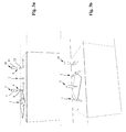
- FIG. 1 schematically shown apparatus for rotating flat goods 10 about an axis perpendicular to the plane 10 standing axis includes a (here only schematically illustrated) retraction device 17 which moves the goods 10 linearly in the transport direction x.
- the retraction device 17 may be, for example, a conveyor belt, in particular a vacuum belt, or transport rollers or the like.
- the device further comprises a first rotary device 1 and a second rotary device 2 arranged downstream of the intake device 17 in the transport direction x.
- a transport device 3 is arranged between the first rotary device 1 and the second rotary device 2.
- the second rotary device 2 is adjoined in the transport direction x by a further transport device 18 and a follower device 9 (which is also shown here only schematically).
- the material is rotated by a predetermined first rotation angle ⁇ 1 and in the second rotation device 2, the material 10 is later rotated by a predetermined second angle of rotation ⁇ 2.
- the rotating means of the two rotating means 1 and 2 include in the in FIG. 1 shown embodiment, in each case a first pair of rotary rollers 1a and 2a and a second pair of rotary rollers 1b and 2b.
- the first rotary roller pair 1a, 2a and the second rotary roller pair 1b, 2b are each arranged in the transverse direction y to the transport direction x at a lateral distance y1 and y2 to each other.
- Each rotary roller pair 1a, 2a; 1b, 2b in each case comprises an upper roller and a lower roller (not shown here), which are each rotatably mounted about an axis extending in the transverse direction y.
- each rotary roller pair 1a, 1b and 2a, 2b is either the upper roller and / or the lower roller with a motor 3a, 3b; 4a, 4b and is driven in rotation by this motor.
- the rollers of the first pair of rotary rollers 1a and the rollers of the second pair of rotary rollers 1b at different speeds from the respective associated motor 3a , 3b are driven.
- the material 10 in engagement with the first rotary device 1 is rotated by a predetermined angle of rotation ⁇ 1.
- the rotation angle ⁇ 1 depends on the differential speed between the first pair of rotary rollers 1a and the second Turning pair 1b from. Accordingly, a material 10, which is in engagement with the pair of pairs of rotary rollers 2a and 2b of the second rotary device 2, can be rotated by a predetermined angle of rotation ⁇ 2 by moving the rollers of the first roller roller pair 2a and the rollers of the second rotary roller pair 2b from the associated motors 4a, 4b are driven at different speeds.
- the rotating roller pairs 1a, 2a or 1b, 2b located on one side with respect to the longitudinal center plane of the device are driven at a constant predetermined speed, which expediently corresponds to the transport speed of the intake device 17.
- the laterally opposed and corresponding pair of rotary rollers is driven at a lower or higher speed, thereby causing rotation of the Guts 10.
- a transport device 3 is arranged, which can move the goods 10 linearly in the transport direction x.
- the transport device 3 takes over the material 10 rotated by the predetermined first rotational angle ⁇ 1 from the first rotary device 1 and then transports the transferred material 10 linearly over a predetermined transport path in the transport direction x. Subsequently, the transport device 3 transfers the moving material 10 to the downstream second rotary device 2.
- the transport device 3 comprises a circulating conveyor belt 5 and a pressure element 6, with the goods 10 can be pressed onto the conveyor belt 5 to bring the goods 10 into engagement with the transport device 3.
- the pressure element 6 is formed by a movable punch 7 with pressure rollers 8 arranged thereon.
- the movable punch 7 is expediently coupled to a drive (not shown here) which can raise and lower the punch 7 in relation to the conveyor belt 5.
- the pressure rollers 8 arranged on the punch 7 are freely rotatably mounted about an axis extending in the y-direction.
- the Good 10 can be brought into engagement with the transport device 3 by the punch 7 is lowered with the pressure rollers 8 arranged thereon in the direction of the conveyor belt 5 until the pressure rollers 8, the Good 10 against the Press conveyor belt 5.
- the good 10 is characterized in the transport direction x moves, wherein the pressure rollers 8 roll on the conveyor belt 5 facing away from the surface of the Guts 10.
- the second rotary device 2 is followed by a further transport device 18 in the transport direction x downwards, the structure and function of which corresponds to the transport device 3.
- the transport device 18 likewise comprises a conveyor belt 13 and a punch 11 movable relative to the conveyor belt 13 with pressure rollers 12 arranged thereon.
- the second rotary device 2 leads the material 10 rotated about the total rotational angle ⁇ finally to the further transport device 18 connected downstream in the transport direction x ( Figure 2g ).
- the second transport device 18 then moves the material 10 located in the second orientation b linearly in the transport direction x to a subsequent trailer device 9 (FIG. Figure 2g ).
- the follower device 9 can be, for example, an alignment device with which a fine alignment of the orientation and the position of the rotated material 10 is carried out.
- the Nachflectr coupled 9 may also be a device for further processing of Guts 10, such.
- As a collection station or a folding station or an inserter which introduces the rotated Good 10 in an envelope.
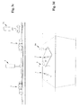
- FIG. 3 a modified embodiment of an inventive device for rotating flat goods 10 is shown in perspective side views.
- This embodiment corresponds to the formation of the conveyor belt 5 substantially the embodiment of FIG. 1 , which is why in FIG. 3 for themselves corresponding parts the same reference numerals are used as in FIG. 1 ,
- the transport devices 3 and 18 instead of a circulating conveyor belt 5 comprise rotating transport rollers 15, 19, which are each rotatably mounted about an axis of rotation extending in the y-direction and are rotationally driven by a motor (not shown).
- the transport rollers 15, 19 opposite each one associated with a liftable and lowerable pressure element 6, which has pressure rollers 8, 12.
- By lowering the pressure element 6 on the associated transport roller 15, 19, a good 10 can be brought into engagement with the respective transport means 3, 18.
- the operation of the device of FIG. 3 corresponds to the embodiment of FIG. 1 ,
- FIGS. 3a to 3f From the side views of FIGS. 3a to 3f In particular, the positions of the transport devices 3 and 18 in the individual stages of the turning operation show.
- the Good 10 In the in FIG. 3a shown level is the Good 10, which is being rotated in the first rotator 1, out of engagement with the transport devices 3 and 18.
- the Good 10 In the in FIGS. 3b and 3c shown level, the Good 10 is in engagement with the first transport device 3, which moves the Good linear and passes to the second rotator 2.
- a subsequent good for the serial processing of the goods can already be transferred to the first rotating device 1 and rotated there as described above. This leads to a considerable reduction of the cycle times and thus to an increase of the cycle performance and the throughput.
- the pressing element 6 of the first transport device 3 is raised, so that the material can then be rotated in the subsequent rotary step in the second rotary device 2 ( 3d figures and 3e ). Finally, the estate will be 10, as in FIG. 3f shown, passed to the second conveyor 18 by this the good engages and continues to move linearly.
- FIG. 4 a further embodiment of a device according to the invention is shown.
- the transport means 3 and 18 are each formed by suction belts 5 'and 13', respectively.
- the suction belts 5 ', 13' can be connected to negative pressure to be switched on and off in order to suck in a material 10 located on the respective suction belt 5 ', 13' and bring it into engagement with the respective transport device 3 or 18.
- FIG. 5 shows a further embodiment of a device according to the invention.
- the transport devices 3 and 18 are each formed by circulating conveyor belts 5 and 13 respectively.
- the conveyor belts 5, 13 have on their surface on such a high adhesion that the goods 10 adhere solely by gravity and static friction on the conveyor belt and are moved by this.
- the material is hereby brought into engagement with the conveyor belt 5 or 13 as soon as it is transferred from the respective upstream rotary device 1 or 2 onto the conveyor belt 5 or 13 and there due to the static friction on the surface of the moving conveyor belt 5 and 13 respectively adheres.
- An additional pressing device 6, as in the embodiments of FIGS. 1 and 2 is not provided here.
- the rotating means of the first rotating device 1 and / or the second rotating device 2 can be configured differently.
- cooperating pairs of rotary rollers 1a, 2a; 1b, 2b can be used as a rotating means, for example, with conveyor belts or belts and thus cooperating roles.
- any means which can impart a defined rotation to a moving material 10 can be used as the rotating means.
- sensors in particular optical sensors, can be used in the devices according to the invention to detect the position and optionally an orientation of the item 10 in different phases of the turning operation.
- a sensor 16 for detecting the front edge of the Guts 10 is shown.
- the signals detected by the sensors are in this case transmitted to a control device for controlling the rotary devices 1, 2 and in particular for controlling the motors 3a, 3b; 4a, 4b, which drive the rotating means of the first rotating means 1 and the second rotating means 2, respectively.
- a control device for controlling the rotary devices 1, 2 and in particular for controlling the motors 3a, 3b; 4a, 4b, which drive the rotating means of the first rotating means 1 and the second rotating means 2, respectively.
- the entire turning process has been divided into two sub-steps, namely in a first sub-step in the first rotating device 1 and a second sub-step in the second rotating device 2. It is also possible to divide the overall turning process into more than two sub-steps and for this purpose provide further rotating devices, which then connect in the transport direction x to the second rotary device 2 and the subsequent transport device 18.
Claims (15)
- Dispositif pour faire tourner des articles (10) plats déplacés dans un sens de transport (x), en particulier de feuilles ou piles de feuille, d'une première orientation (a) à une seconde orientation (b) d'un angle de rotation global (α) prescrit, avec un premier dispositif de rotation (1), dans lequel l'article (10) est tout d'abord tourné d'un premier angle de rotation (α1) et avec au moins un second dispositif de rotation (2), dans lequel l'article (10) est ultérieurement tourné d'un second angle de rotation (α2), dans lequel le premier dispositif de rotation (1) et le second dispositif de rotation (2) sont agencés l'un derrière l'autre dans le sens de transport (x), dans lequel un dispositif de transport (3) est agencé entre le premier dispositif de rotation (1) et le second dispositif de rotation (2), lequel déplace encore l'article tourné dans le premier dispositif de rotation (1) du premier angle de rotation (α1) linéairement dans le sens de transport (x) et le remet pour la suite de la rotation au second dispositif de rotation (2), caractérisé en ce que
le dispositif de transport (3) peut être commuté entre une première position, dans laquelle il met en prise un article (10), et une seconde position, dans laquelle l'article (10) n'est pas mis en prise par le dispositif de transport (3). - Dispositif selon la revendication 1, caractérisé en ce que le premier dispositif de rotation (1) et/ou le second dispositif de rotation (2) présentent une première paire de rouleaux de rotation (1a, 2a) et une seconde paire de rouleaux de rotation (1b, 2b), dans lequel la première paire de rouleaux de rotation (1a, 2a) et la seconde paire de rouleaux de rotation (1b, 2b) sont agencées dans le sens transversal (y) par rapport au sens de transport (x) à une distance latérale (y1 ; y2) l'une par rapport à l'autre et entraînées en rotation pour la rotation de l'article (10) à différentes vitesses de rotation par un moteur (3a, 3b ; 4a, 4b).
- Dispositif selon l'une quelconque des revendications précédentes, caractérisé en ce que la somme du premier angle de rotation (α1) et du second angle de rotation (α2) est inférieure ou égale à l'angle de rotation global (α) qui s'élève en particulier à 90°.
- Dispositif selon la revendication 2, caractérisé en ce que la distance latérale (y1, y2) des paires de rouleaux de rotation correspondantes (1a, 1b ; 2a, 2b) du premier dispositif de rotation (1) et/ou du second dispositif de rotation (2) est réglable et peut être adaptée en particulier au format de l'article (10).
- Dispositif selon l'une quelconque des revendications précédentes, caractérisé en ce que le dispositif de transport (3) est amené dans sa première position, dans laquelle il met en prise un article (10) après que l'article (10) a été tourné dans le premier dispositif de rotation (1) du premier angle de rotation prescrit (α1) et/ou en ce que le dispositif de transport (3) est amené dans sa seconde position, dans laquelle l'article (10) n'est pas mis en prise par le dispositif de transport (3) après que l'article (10) a été transmis au second dispositif de rotation (2).
- Dispositif selon l'une quelconque des revendications précédentes, caractérisé en ce que le dispositif de transport (3) comporte au moins un élément de transport (5 ; 15, 19) entraîné, en particulier une bande de transport (5) ou des rouleaux de transport (15, 19), ainsi qu'un élément de pressage (6) qui est mobile par rapport à l'élément de transport (5 ; 15, 19) afin de mettre en prise l'article avec l'élément de transport (5 ; 15, 19).
- Dispositif selon la revendication 6, caractérisé en ce que l'élément de pressage (6) est formé par un poinçon mobile (7) avec des rouleaux de pressage (8), dans lequel le poinçon mobile (7) est couplé à un entraînement qui peut lever et abaisser le poinçon (7) par rapport à l'élément de transport (5 ; 15, 19).
- Dispositif selon l'une quelconque des revendications précédentes, caractérisé en ce que le dispositif comporte au moins un capteur optique (16) pour la détection de la position et/ou de l'orientation de l'article (10).
- Dispositif selon l'une quelconque des revendications précédentes, caractérisé en ce que le dispositif de transport (3) comporte une courroie d'aspiration pouvant être alimentée en dépression par enclenchement ou désenclenchement, laquelle aspire l'article à l'aide de la dépression afin de le mettre en prise avec le dispositif de transport (3), dans lequel l'article (10) peut être dégagé du dispositif de transport (3) par dégagement de la dépression.
- Dispositif selon l'une quelconque des revendications précédentes, caractérisé en ce qu'un dispositif de rentrée (17) qui déplace l'article (10) se trouvant dans une première orientation tout d'abord linéairement dans le sens de transport et le transmet ensuite au premier dispositif de rotation (1), est agencé vu dans le sens de transport devant le premier dispositif de rotation.
- Dispositif selon l'une quelconque des revendications précédentes, caractérisé en ce qu'un autre dispositif de transport (18) qui reprend l'article (10) venant du second dispositif de rotation (2) et le déplace encore tout d'abord linéairement dans le sens de transport et le remet ensuite à un autre dispositif de rotation ou à un dispositif suiveur (9), est agencé vu dans le sens de transport après le second dispositif de rotation (2).
- Dispositif selon la revendication 11, caractérisé en ce qu'il s'agit, pour le dispositif suiveur (9), d'un dispositif d'orientation pour l'orientation de l'article, avec lequel une orientation fine de l'orientation et de la position de l'article (10) tourné peut être réalisée et/ou d'éventuelles erreurs d'angle de l'article peuvent être corrigées.
- Procédé de rotation d'articles (10) plats déplacés dans un sens de transport (x), en particulier de feuilles ou piles de feuille d'une première orientation (a) à une seconde orientation (b) d'un angle de rotation global (α), dans lequel l'article (10) est tourné dans un premier dispositif de rotation (1) d'un premier angle de rotation (α1) et dans un second dispositif de rotation (2) d'un second angle de rotation (α2) et dans lequel le premier dispositif de rotation (1) et le second dispositif de rotation (2) sont agencés dans le sens de transport (x) l'un derrière l'autre, dans lequel le processus de rotation est découplé dans le premier dispositif de rotation (1) et le second dispositif de rotation (2) par un dispositif de transport (3) agencé entre le premier dispositif de rotation (1) et le second dispositif de rotation (2), lequel déplace encore l'article tourné dans le premier dispositif de rotation (1) du premier angle de rotation (α1) linéairement dans le sens de transport (x) et le remet pour la suite de la rotation au second dispositif de rotation (2), caractérisé en ce que
le dispositif de transport (3) peut être commuté entre une première position, dans laquelle il met en prise un article (10) et une seconde position, dans laquelle l'article (10) n'est pas mis en prise par le dispositif de transport (3). - Procédé selon la revendication 13, caractérisé en ce que l'article (10) est déplacé linéairement dans le premier dispositif (1) tout d'abord d'un parcours d'entrée prescrit dans le sens de transport (x) avant qu'il ne soit tourné dans l'étape de procédé suivante du premier angle de rotation (α1) et/ou en ce que l'article (10) est encore déplacé linéairement après la rotation dans le premier dispositif de rotation (1), d'un parcours de sortie prescrit dans le sens de transport (x) avant qu'il ne soit remis dans une étape de procédé suivante au dispositif de transport (3).
- Procédé selon la revendication 13 ou 14, caractérisé en ce que l'article (10) est déplacé linéairement dans le second dispositif de rotation (2) tour d'abord d'un parcours d'entrée prescrit dans le sens de transport (x) avant qu'il ne soit tourné dans l'étape de procédé suivante du second angle de rotation (α2) et/ou en ce que l'article (10) est encore déplacé linéairement après la rotation dans le second dispositif de rotation (1) autour d'un parcours de sortie prescrit dans le sens de transport (x) avant qu'il ne soit remis dans une étape de procédé terminale à un autre dispositif de transport (18) ou à un dispositif suiveur (9).
Applications Claiming Priority (2)
| Application Number | Priority Date | Filing Date | Title |
|---|---|---|---|
| DE102012112719.0A DE102012112719A1 (de) | 2012-12-20 | 2012-12-20 | Vorrichtung und Verfahren zum Drehen von flachen Gütern |
| PCT/EP2013/076546 WO2014095634A1 (fr) | 2012-12-20 | 2013-12-13 | Dispositif et procédé permettant de faire tourner des articles plats |
Publications (2)
| Publication Number | Publication Date |
|---|---|
| EP2935060A1 EP2935060A1 (fr) | 2015-10-28 |
| EP2935060B1 true EP2935060B1 (fr) | 2016-11-30 |
Family
ID=49766087
Family Applications (1)
| Application Number | Title | Priority Date | Filing Date |
|---|---|---|---|
| EP13805870.6A Active EP2935060B1 (fr) | 2012-12-20 | 2013-12-13 | Dispositif et procédé permettant de faire tourner des articles plats |
Country Status (3)
| Country | Link |
|---|---|
| EP (1) | EP2935060B1 (fr) |
| DE (1) | DE102012112719A1 (fr) |
| WO (1) | WO2014095634A1 (fr) |
Families Citing this family (2)
| Publication number | Priority date | Publication date | Assignee | Title |
|---|---|---|---|---|
| EP3763646B1 (fr) | 2019-07-11 | 2021-08-11 | Müller Apparatebau GmbH | Dispositif et procédé de transfert des feuilles entre des unités de transport |
| CN110436230A (zh) * | 2019-09-19 | 2019-11-12 | 李青安 | 一种真空运纸卧式模切压痕(烫印)机 |
Family Cites Families (14)
| Publication number | Priority date | Publication date | Assignee | Title |
|---|---|---|---|---|
| US3758104A (en) | 1971-09-23 | 1973-09-11 | W Daily | Turning apparatus |
| IT8322476A0 (it) * | 1983-08-08 | 1983-08-08 | Francesco Canziani | L'attuazione di detto procedimento. procedimento per alimentare in particolare apparecchiature smistatrici con immissione dei colli essendo una predeterminata angolazione ed apparecchiatura per |
| DE8519708U1 (de) * | 1985-07-08 | 1985-09-12 | Maschinenbau Louise GmbH, 5000 Köln | Leiteinrichtung an einer Vorrichtung zum Palettieren von gefüllten Säcken od.dgl. |
| CH673830A5 (fr) | 1986-02-12 | 1990-04-12 | Will E C H Gmbh & Co | |
| JPH0680242A (ja) * | 1992-09-04 | 1994-03-22 | Hitachi Electron Eng Co Ltd | ワーク搬送処理ライン |
| EP0814041B1 (fr) | 1996-06-17 | 2001-11-14 | C.P. Bourg S.A. | Procédé pour tourner des feuilles et empiler de feuilles muni d'un dispositif pour tourner des feuilles |
| NL1013670C2 (nl) * | 1999-11-25 | 2001-05-28 | Ocu Technologies B V | Werkwijze voor het in zijdelings register brengen van een vel met een daarop over te dragen beeld. |
| JP4845658B2 (ja) * | 2006-04-07 | 2011-12-28 | キヤノン株式会社 | シート搬送装置およびこれを備えた画像形成装置 |
| DE102007024945A1 (de) * | 2006-06-06 | 2007-12-13 | Eastman Kodak Co. | Verfahren und Vorrichtung zum Transport eines Bogens in einer Druckmaschine |
| US20090107892A1 (en) | 2007-10-31 | 2009-04-30 | Pitney Bowes Inc. | Sheet material transposition for sorting apparatus |
| DE102008050524A1 (de) * | 2008-10-06 | 2010-04-08 | Wincor Nixdorf International Gmbh | Vorrichtung zum Ausrichten von Wertscheinen |
| JP2010285244A (ja) * | 2009-06-10 | 2010-12-24 | Toshiba Corp | 姿勢変換装置、および紙葉類処理装置 |
| EP2621843B1 (fr) * | 2010-09-27 | 2016-05-11 | OCE-Technologies B.V. | Dispositif d'acheminement de feuille |
| ITMI20112055A1 (it) * | 2011-11-11 | 2013-05-12 | Sitma Machinery S P A | Apparato e metodo per controllare e modificare l'orientazione di prodotti in formato a libro trasportati in un flusso continuo di trasporto |
-
2012
- 2012-12-20 DE DE102012112719.0A patent/DE102012112719A1/de not_active Withdrawn
-
2013
- 2013-12-13 EP EP13805870.6A patent/EP2935060B1/fr active Active
- 2013-12-13 WO PCT/EP2013/076546 patent/WO2014095634A1/fr active Application Filing
Non-Patent Citations (1)
| Title |
|---|
| None * |
Also Published As
| Publication number | Publication date |
|---|---|
| WO2014095634A1 (fr) | 2014-06-26 |
| DE102012112719A1 (de) | 2014-06-26 |
| EP2935060A1 (fr) | 2015-10-28 |
Similar Documents
| Publication | Publication Date | Title |
|---|---|---|
| EP2411313B1 (fr) | Procédé destiné à la correction d'une position inclinée d'un produit sortant d'un espace séparant deux cylindres de pliage d'une plieuse longitudinale et plieuse longitudinale | |
| EP2883820B1 (fr) | Dispositif et procédé destiné à cadencer des corps d'ouvrage | |
| EP1460009B1 (fr) | Dispositif d'alignement de feuilles | |
| DE19758732B4 (de) | Vorrichtung zum Stapel von Büchern | |
| EP2444344A1 (fr) | Plieuse de feuilles et procédé de fonctionnement d'une plieuse | |
| EP2935060B1 (fr) | Dispositif et procédé permettant de faire tourner des articles plats | |
| EP2133295A1 (fr) | Dispositif et procédé destinés à extraire des produits d'impression plats d'une pile et à les transmettre à un dispositif de transport déroulant | |
| EP2746204B1 (fr) | Dispositif et procédé destinés à faire tourner des objets plats | |
| EP2559549B1 (fr) | Dispositif et procédé de traitement de feuilles de papier ou d'un autre matériau flexible | |
| EP3533609B1 (fr) | Dispositif et procédé de traitement ultérieur séquentiel de feuilles imprimées | |
| DE3330681A1 (de) | Verfahren zum schnellen zufuehren und transportieren von blattfoermigen papiererzeugnissen und vorrichtung zur durchfuehrung des verfahrens | |
| DE102017221220B4 (de) | Bogenverarbeitende Maschine | |
| EP1661833A1 (fr) | Procédé et dispositif pour traiter des produits imprimés | |
| EP3059195B1 (fr) | Dispositif de pliage et procédé | |
| EP3957582A1 (fr) | Dispositif et procédé d'alimentation de produits plans à une unité de traitement | |
| EP1612174B1 (fr) | Dispositif d'alignement de feuilles empilées | |
| EP2192057B1 (fr) | Dispositif de transport de produits | |
| EP1554059B1 (fr) | Dispositif d'alimentation precise d'elements de tri plats a un dispositif d'entree destine a un convoyeur de tri | |
| DE19608939A1 (de) | Einrichtung zur Vereinzelung und Beschleunigung von Druckprodukten | |
| EP1655244A2 (fr) | Procédé et dispositif de séparation d'articles plats d'une pile horizontale | |
| DE102015004857A1 (de) | Verfahren und Vorrichtung zum Beladen einer Dreimesserschneidemaschine mit Schneidgut | |
| EP2088104B1 (fr) | Dispositif destiné au détournement de produits d'impression isolés | |
| CH701619A1 (de) | Vorrichtung und Verfahren zum Falzen von Druckereiprodukten. | |
| WO2009024453A1 (fr) | Dispositif d'alimentation, bande transporteuse, machine de traitement de feuilles et procédé pour acheminer des feuilles provenant d'une pile | |
| WO2008067983A2 (fr) | Procédé et dispositif permettant de retirer un flux de produit |
Legal Events
| Date | Code | Title | Description |
|---|---|---|---|
| PUAI | Public reference made under article 153(3) epc to a published international application that has entered the european phase |
Free format text: ORIGINAL CODE: 0009012 |
|
| 17P | Request for examination filed |
Effective date: 20150720 |
|
| AK | Designated contracting states |
Kind code of ref document: A1 Designated state(s): AL AT BE BG CH CY CZ DE DK EE ES FI FR GB GR HR HU IE IS IT LI LT LU LV MC MK MT NL NO PL PT RO RS SE SI SK SM TR |
|
| AX | Request for extension of the european patent |
Extension state: BA ME |
|
| DAX | Request for extension of the european patent (deleted) | ||
| GRAP | Despatch of communication of intention to grant a patent |
Free format text: ORIGINAL CODE: EPIDOSNIGR1 |
|
| INTG | Intention to grant announced |
Effective date: 20160726 |
|
| GRAS | Grant fee paid |
Free format text: ORIGINAL CODE: EPIDOSNIGR3 |
|
| GRAA | (expected) grant |
Free format text: ORIGINAL CODE: 0009210 |
|
| AK | Designated contracting states |
Kind code of ref document: B1 Designated state(s): AL AT BE BG CH CY CZ DE DK EE ES FI FR GB GR HR HU IE IS IT LI LT LU LV MC MK MT NL NO PL PT RO RS SE SI SK SM TR |
|
| REG | Reference to a national code |
Ref country code: CH Ref legal event code: EP Ref country code: CH Ref legal event code: NV Representative=s name: LUCHS AND PARTNER AG PATENTANWAELTE, CH Ref country code: GB Ref legal event code: FG4D Free format text: NOT ENGLISH |
|
| REG | Reference to a national code |
Ref country code: AT Ref legal event code: REF Ref document number: 849577 Country of ref document: AT Kind code of ref document: T Effective date: 20161215 |
|
| REG | Reference to a national code |
Ref country code: IE Ref legal event code: FG4D Free format text: LANGUAGE OF EP DOCUMENT: GERMAN |
|
| REG | Reference to a national code |
Ref country code: DE Ref legal event code: R096 Ref document number: 502013005615 Country of ref document: DE |
|
| PG25 | Lapsed in a contracting state [announced via postgrant information from national office to epo] |
Ref country code: LV Free format text: LAPSE BECAUSE OF FAILURE TO SUBMIT A TRANSLATION OF THE DESCRIPTION OR TO PAY THE FEE WITHIN THE PRESCRIBED TIME-LIMIT Effective date: 20161130 |
|
| REG | Reference to a national code |
Ref country code: LT Ref legal event code: MG4D |
|
| REG | Reference to a national code |
Ref country code: NL Ref legal event code: MP Effective date: 20161130 |
|
| PG25 | Lapsed in a contracting state [announced via postgrant information from national office to epo] |
Ref country code: GR Free format text: LAPSE BECAUSE OF FAILURE TO SUBMIT A TRANSLATION OF THE DESCRIPTION OR TO PAY THE FEE WITHIN THE PRESCRIBED TIME-LIMIT Effective date: 20170301 Ref country code: NO Free format text: LAPSE BECAUSE OF FAILURE TO SUBMIT A TRANSLATION OF THE DESCRIPTION OR TO PAY THE FEE WITHIN THE PRESCRIBED TIME-LIMIT Effective date: 20170228 Ref country code: SE Free format text: LAPSE BECAUSE OF FAILURE TO SUBMIT A TRANSLATION OF THE DESCRIPTION OR TO PAY THE FEE WITHIN THE PRESCRIBED TIME-LIMIT Effective date: 20161130 Ref country code: LT Free format text: LAPSE BECAUSE OF FAILURE TO SUBMIT A TRANSLATION OF THE DESCRIPTION OR TO PAY THE FEE WITHIN THE PRESCRIBED TIME-LIMIT Effective date: 20161130 |
|
| PG25 | Lapsed in a contracting state [announced via postgrant information from national office to epo] |
Ref country code: FI Free format text: LAPSE BECAUSE OF FAILURE TO SUBMIT A TRANSLATION OF THE DESCRIPTION OR TO PAY THE FEE WITHIN THE PRESCRIBED TIME-LIMIT Effective date: 20161130 Ref country code: RS Free format text: LAPSE BECAUSE OF FAILURE TO SUBMIT A TRANSLATION OF THE DESCRIPTION OR TO PAY THE FEE WITHIN THE PRESCRIBED TIME-LIMIT Effective date: 20161130 Ref country code: HR Free format text: LAPSE BECAUSE OF FAILURE TO SUBMIT A TRANSLATION OF THE DESCRIPTION OR TO PAY THE FEE WITHIN THE PRESCRIBED TIME-LIMIT Effective date: 20161130 Ref country code: PL Free format text: LAPSE BECAUSE OF FAILURE TO SUBMIT A TRANSLATION OF THE DESCRIPTION OR TO PAY THE FEE WITHIN THE PRESCRIBED TIME-LIMIT Effective date: 20161130 Ref country code: PT Free format text: LAPSE BECAUSE OF FAILURE TO SUBMIT A TRANSLATION OF THE DESCRIPTION OR TO PAY THE FEE WITHIN THE PRESCRIBED TIME-LIMIT Effective date: 20170330 Ref country code: ES Free format text: LAPSE BECAUSE OF FAILURE TO SUBMIT A TRANSLATION OF THE DESCRIPTION OR TO PAY THE FEE WITHIN THE PRESCRIBED TIME-LIMIT Effective date: 20161130 Ref country code: BE Free format text: LAPSE BECAUSE OF NON-PAYMENT OF DUE FEES Effective date: 20161231 |
|
| PG25 | Lapsed in a contracting state [announced via postgrant information from national office to epo] |
Ref country code: NL Free format text: LAPSE BECAUSE OF FAILURE TO SUBMIT A TRANSLATION OF THE DESCRIPTION OR TO PAY THE FEE WITHIN THE PRESCRIBED TIME-LIMIT Effective date: 20161130 |
|
| PG25 | Lapsed in a contracting state [announced via postgrant information from national office to epo] |
Ref country code: CZ Free format text: LAPSE BECAUSE OF FAILURE TO SUBMIT A TRANSLATION OF THE DESCRIPTION OR TO PAY THE FEE WITHIN THE PRESCRIBED TIME-LIMIT Effective date: 20161130 Ref country code: RO Free format text: LAPSE BECAUSE OF FAILURE TO SUBMIT A TRANSLATION OF THE DESCRIPTION OR TO PAY THE FEE WITHIN THE PRESCRIBED TIME-LIMIT Effective date: 20161130 Ref country code: EE Free format text: LAPSE BECAUSE OF FAILURE TO SUBMIT A TRANSLATION OF THE DESCRIPTION OR TO PAY THE FEE WITHIN THE PRESCRIBED TIME-LIMIT Effective date: 20161130 Ref country code: DK Free format text: LAPSE BECAUSE OF FAILURE TO SUBMIT A TRANSLATION OF THE DESCRIPTION OR TO PAY THE FEE WITHIN THE PRESCRIBED TIME-LIMIT Effective date: 20161130 Ref country code: SK Free format text: LAPSE BECAUSE OF FAILURE TO SUBMIT A TRANSLATION OF THE DESCRIPTION OR TO PAY THE FEE WITHIN THE PRESCRIBED TIME-LIMIT Effective date: 20161130 |
|
| PG25 | Lapsed in a contracting state [announced via postgrant information from national office to epo] |
Ref country code: IT Free format text: LAPSE BECAUSE OF FAILURE TO SUBMIT A TRANSLATION OF THE DESCRIPTION OR TO PAY THE FEE WITHIN THE PRESCRIBED TIME-LIMIT Effective date: 20161130 Ref country code: SM Free format text: LAPSE BECAUSE OF FAILURE TO SUBMIT A TRANSLATION OF THE DESCRIPTION OR TO PAY THE FEE WITHIN THE PRESCRIBED TIME-LIMIT Effective date: 20161130 Ref country code: BG Free format text: LAPSE BECAUSE OF FAILURE TO SUBMIT A TRANSLATION OF THE DESCRIPTION OR TO PAY THE FEE WITHIN THE PRESCRIBED TIME-LIMIT Effective date: 20170228 |
|
| REG | Reference to a national code |
Ref country code: DE Ref legal event code: R097 Ref document number: 502013005615 Country of ref document: DE |
|
| PG25 | Lapsed in a contracting state [announced via postgrant information from national office to epo] |
Ref country code: MC Free format text: LAPSE BECAUSE OF FAILURE TO SUBMIT A TRANSLATION OF THE DESCRIPTION OR TO PAY THE FEE WITHIN THE PRESCRIBED TIME-LIMIT Effective date: 20161130 |
|
| REG | Reference to a national code |
Ref country code: IE Ref legal event code: MM4A |
|
| PLBE | No opposition filed within time limit |
Free format text: ORIGINAL CODE: 0009261 |
|
| STAA | Information on the status of an ep patent application or granted ep patent |
Free format text: STATUS: NO OPPOSITION FILED WITHIN TIME LIMIT |
|
| PG25 | Lapsed in a contracting state [announced via postgrant information from national office to epo] |
Ref country code: LU Free format text: LAPSE BECAUSE OF NON-PAYMENT OF DUE FEES Effective date: 20161213 |
|
| 26N | No opposition filed |
Effective date: 20170831 |
|
| REG | Reference to a national code |
Ref country code: FR Ref legal event code: ST Effective date: 20171025 |
|
| PG25 | Lapsed in a contracting state [announced via postgrant information from national office to epo] |
Ref country code: SI Free format text: LAPSE BECAUSE OF FAILURE TO SUBMIT A TRANSLATION OF THE DESCRIPTION OR TO PAY THE FEE WITHIN THE PRESCRIBED TIME-LIMIT Effective date: 20161130 Ref country code: IE Free format text: LAPSE BECAUSE OF NON-PAYMENT OF DUE FEES Effective date: 20161213 |
|
| PG25 | Lapsed in a contracting state [announced via postgrant information from national office to epo] |
Ref country code: FR Free format text: LAPSE BECAUSE OF NON-PAYMENT OF DUE FEES Effective date: 20170130 |
|
| REG | Reference to a national code |
Ref country code: BE Ref legal event code: MM Effective date: 20161231 |
|
| PG25 | Lapsed in a contracting state [announced via postgrant information from national office to epo] |
Ref country code: HU Free format text: LAPSE BECAUSE OF FAILURE TO SUBMIT A TRANSLATION OF THE DESCRIPTION OR TO PAY THE FEE WITHIN THE PRESCRIBED TIME-LIMIT; INVALID AB INITIO Effective date: 20131213 |
|
| PG25 | Lapsed in a contracting state [announced via postgrant information from national office to epo] |
Ref country code: IS Free format text: LAPSE BECAUSE OF FAILURE TO SUBMIT A TRANSLATION OF THE DESCRIPTION OR TO PAY THE FEE WITHIN THE PRESCRIBED TIME-LIMIT Effective date: 20161130 Ref country code: MK Free format text: LAPSE BECAUSE OF FAILURE TO SUBMIT A TRANSLATION OF THE DESCRIPTION OR TO PAY THE FEE WITHIN THE PRESCRIBED TIME-LIMIT Effective date: 20161130 Ref country code: CY Free format text: LAPSE BECAUSE OF FAILURE TO SUBMIT A TRANSLATION OF THE DESCRIPTION OR TO PAY THE FEE WITHIN THE PRESCRIBED TIME-LIMIT Effective date: 20161130 |
|
| GBPC | Gb: european patent ceased through non-payment of renewal fee |
Effective date: 20171213 |
|
| PG25 | Lapsed in a contracting state [announced via postgrant information from national office to epo] |
Ref country code: MT Free format text: LAPSE BECAUSE OF FAILURE TO SUBMIT A TRANSLATION OF THE DESCRIPTION OR TO PAY THE FEE WITHIN THE PRESCRIBED TIME-LIMIT Effective date: 20161130 |
|
| PG25 | Lapsed in a contracting state [announced via postgrant information from national office to epo] |
Ref country code: TR Free format text: LAPSE BECAUSE OF FAILURE TO SUBMIT A TRANSLATION OF THE DESCRIPTION OR TO PAY THE FEE WITHIN THE PRESCRIBED TIME-LIMIT Effective date: 20161130 |
|
| PG25 | Lapsed in a contracting state [announced via postgrant information from national office to epo] |
Ref country code: GB Free format text: LAPSE BECAUSE OF NON-PAYMENT OF DUE FEES Effective date: 20171213 |
|
| REG | Reference to a national code |
Ref country code: AT Ref legal event code: MM01 Ref document number: 849577 Country of ref document: AT Kind code of ref document: T Effective date: 20181213 |
|
| PG25 | Lapsed in a contracting state [announced via postgrant information from national office to epo] |
Ref country code: AT Free format text: LAPSE BECAUSE OF NON-PAYMENT OF DUE FEES Effective date: 20181213 |
|
| PG25 | Lapsed in a contracting state [announced via postgrant information from national office to epo] |
Ref country code: AL Free format text: LAPSE BECAUSE OF FAILURE TO SUBMIT A TRANSLATION OF THE DESCRIPTION OR TO PAY THE FEE WITHIN THE PRESCRIBED TIME-LIMIT Effective date: 20161130 |
|
| PGFP | Annual fee paid to national office [announced via postgrant information from national office to epo] |
Ref country code: CH Payment date: 20230103 Year of fee payment: 10 |
|
| P01 | Opt-out of the competence of the unified patent court (upc) registered |
Effective date: 20230515 |
|
| PGFP | Annual fee paid to national office [announced via postgrant information from national office to epo] |
Ref country code: DE Payment date: 20231214 Year of fee payment: 11 |