EP2934728B1 - Verfahren und vorrichtung zur übertragung von gasmolekülen von einem gasförmigen medium in ein flüssiges medium oder umgekehrt - Google Patents
Verfahren und vorrichtung zur übertragung von gasmolekülen von einem gasförmigen medium in ein flüssiges medium oder umgekehrt Download PDFInfo
- Publication number
- EP2934728B1 EP2934728B1 EP13814040.5A EP13814040A EP2934728B1 EP 2934728 B1 EP2934728 B1 EP 2934728B1 EP 13814040 A EP13814040 A EP 13814040A EP 2934728 B1 EP2934728 B1 EP 2934728B1
- Authority
- EP
- European Patent Office
- Prior art keywords
- gas
- liquid medium
- membrane
- medium
- particles
- Prior art date
- Legal status (The legal status is an assumption and is not a legal conclusion. Google has not performed a legal analysis and makes no representation as to the accuracy of the status listed.)
- Active
Links
Images



Classifications
-
- B—PERFORMING OPERATIONS; TRANSPORTING
- B01—PHYSICAL OR CHEMICAL PROCESSES OR APPARATUS IN GENERAL
- B01F—MIXING, e.g. DISSOLVING, EMULSIFYING OR DISPERSING
- B01F23/00—Mixing according to the phases to be mixed, e.g. dispersing or emulsifying
- B01F23/20—Mixing gases with liquids
- B01F23/23—Mixing gases with liquids by introducing gases into liquid media, e.g. for producing aerated liquids
- B01F23/231—Mixing gases with liquids by introducing gases into liquid media, e.g. for producing aerated liquids by bubbling
- B01F23/23105—Arrangement or manipulation of the gas bubbling devices
- B01F23/2312—Diffusers
- B01F23/23124—Diffusers consisting of flexible porous or perforated material, e.g. fabric
-
- A—HUMAN NECESSITIES
- A61—MEDICAL OR VETERINARY SCIENCE; HYGIENE
- A61M—DEVICES FOR INTRODUCING MEDIA INTO, OR ONTO, THE BODY; DEVICES FOR TRANSDUCING BODY MEDIA OR FOR TAKING MEDIA FROM THE BODY; DEVICES FOR PRODUCING OR ENDING SLEEP OR STUPOR
- A61M1/00—Suction or pumping devices for medical purposes; Devices for carrying-off, for treatment of, or for carrying-over, body-liquids; Drainage systems
- A61M1/14—Dialysis systems; Artificial kidneys; Blood oxygenators ; Reciprocating systems for treatment of body fluids, e.g. single needle systems for hemofiltration or pheresis
- A61M1/32—Oxygenators without membranes
-
- B—PERFORMING OPERATIONS; TRANSPORTING
- B01—PHYSICAL OR CHEMICAL PROCESSES OR APPARATUS IN GENERAL
- B01D—SEPARATION
- B01D19/00—Degasification of liquids
- B01D19/0031—Degasification of liquids by filtration
-
- B—PERFORMING OPERATIONS; TRANSPORTING
- B01—PHYSICAL OR CHEMICAL PROCESSES OR APPARATUS IN GENERAL
- B01D—SEPARATION
- B01D53/00—Separation of gases or vapours; Recovering vapours of volatile solvents from gases; Chemical or biological purification of waste gases, e.g. engine exhaust gases, smoke, fumes, flue gases, aerosols
- B01D53/22—Separation of gases or vapours; Recovering vapours of volatile solvents from gases; Chemical or biological purification of waste gases, e.g. engine exhaust gases, smoke, fumes, flue gases, aerosols by diffusion
- B01D53/228—Separation of gases or vapours; Recovering vapours of volatile solvents from gases; Chemical or biological purification of waste gases, e.g. engine exhaust gases, smoke, fumes, flue gases, aerosols by diffusion characterised by specific membranes
-
- B—PERFORMING OPERATIONS; TRANSPORTING
- B01—PHYSICAL OR CHEMICAL PROCESSES OR APPARATUS IN GENERAL
- B01D—SEPARATION
- B01D53/00—Separation of gases or vapours; Recovering vapours of volatile solvents from gases; Chemical or biological purification of waste gases, e.g. engine exhaust gases, smoke, fumes, flue gases, aerosols
- B01D53/22—Separation of gases or vapours; Recovering vapours of volatile solvents from gases; Chemical or biological purification of waste gases, e.g. engine exhaust gases, smoke, fumes, flue gases, aerosols by diffusion
- B01D53/229—Integrated processes (Diffusion and at least one other process, e.g. adsorption, absorption)
-
- B—PERFORMING OPERATIONS; TRANSPORTING
- B01—PHYSICAL OR CHEMICAL PROCESSES OR APPARATUS IN GENERAL
- B01D—SEPARATION
- B01D69/00—Semi-permeable membranes for separation processes or apparatus characterised by their form, structure or properties; Manufacturing processes specially adapted therefor
- B01D69/02—Semi-permeable membranes for separation processes or apparatus characterised by their form, structure or properties; Manufacturing processes specially adapted therefor characterised by their properties
-
- B—PERFORMING OPERATIONS; TRANSPORTING
- B01—PHYSICAL OR CHEMICAL PROCESSES OR APPARATUS IN GENERAL
- B01D—SEPARATION
- B01D69/00—Semi-permeable membranes for separation processes or apparatus characterised by their form, structure or properties; Manufacturing processes specially adapted therefor
- B01D69/14—Dynamic membranes
- B01D69/141—Heterogeneous membranes, e.g. containing dispersed material; Mixed matrix membranes
- B01D69/148—Organic/inorganic mixed matrix membranes
-
- A—HUMAN NECESSITIES
- A61—MEDICAL OR VETERINARY SCIENCE; HYGIENE
- A61M—DEVICES FOR INTRODUCING MEDIA INTO, OR ONTO, THE BODY; DEVICES FOR TRANSDUCING BODY MEDIA OR FOR TAKING MEDIA FROM THE BODY; DEVICES FOR PRODUCING OR ENDING SLEEP OR STUPOR
- A61M1/00—Suction or pumping devices for medical purposes; Devices for carrying-off, for treatment of, or for carrying-over, body-liquids; Drainage systems
- A61M1/14—Dialysis systems; Artificial kidneys; Blood oxygenators ; Reciprocating systems for treatment of body fluids, e.g. single needle systems for hemofiltration or pheresis
- A61M1/16—Dialysis systems; Artificial kidneys; Blood oxygenators ; Reciprocating systems for treatment of body fluids, e.g. single needle systems for hemofiltration or pheresis with membranes
- A61M1/1698—Blood oxygenators with or without heat-exchangers
-
- B—PERFORMING OPERATIONS; TRANSPORTING
- B01—PHYSICAL OR CHEMICAL PROCESSES OR APPARATUS IN GENERAL
- B01D—SEPARATION
- B01D2325/00—Details relating to properties of membranes
- B01D2325/02—Details relating to pores or porosity of the membranes
- B01D2325/0283—Pore size
- B01D2325/02834—Pore size more than 0.1 and up to 1 µm
-
- B—PERFORMING OPERATIONS; TRANSPORTING
- B01—PHYSICAL OR CHEMICAL PROCESSES OR APPARATUS IN GENERAL
- B01D—SEPARATION
- B01D2325/00—Details relating to properties of membranes
- B01D2325/38—Hydrophobic membranes
-
- B—PERFORMING OPERATIONS; TRANSPORTING
- B01—PHYSICAL OR CHEMICAL PROCESSES OR APPARATUS IN GENERAL
- B01F—MIXING, e.g. DISSOLVING, EMULSIFYING OR DISPERSING
- B01F23/00—Mixing according to the phases to be mixed, e.g. dispersing or emulsifying
- B01F23/20—Mixing gases with liquids
- B01F23/23—Mixing gases with liquids by introducing gases into liquid media, e.g. for producing aerated liquids
- B01F23/231—Mixing gases with liquids by introducing gases into liquid media, e.g. for producing aerated liquids by bubbling
- B01F23/23105—Arrangement or manipulation of the gas bubbling devices
- B01F23/2312—Diffusers
- B01F23/23124—Diffusers consisting of flexible porous or perforated material, e.g. fabric
- B01F23/231244—Dissolving, hollow fiber membranes
Definitions
- the present invention relates to a method and device for exchanging gas molecules between a gaseous medium and a liquid medium. More specific embodiments of the invention relate to improved methods and devices for gas transfer in applications such as blood oxygenation in heart-lung machines and gas scrubbing.
- Vascular and parenchymal heart and lung diseases represent a major disease burden, socioeconomic problem and are frequent cause of death. Their growing incidence associated with the aging population stimulated research activities with respect to better methods of prevention, diagnosis and treatment. These activities also include the development of improved heart-lung machines.
- extracorporal circulation during open heart surgery or lung operation has developed into a routine procedure. In order to supply the body with sufficient oxygen a heart-lung machine takes over the heart's pumping action and the lung's gas exchange function during surgeries.
- a membrane oxygenator as currently used consists of a gas-permeable membrane, typically made of multilayered membrane sheets of microporous polypropylene, silicone rubber, or thousands of silica, polypropyleneor polyethylene capillaries. To achieve a large gas exchange capacity, gas and blood flow on opposite sides of the membrane, permitting the blood cells to adsorb oxygen molecules directly.
- heparin can be added to blood or the components of the blood circuit can be provided with a heparin coating. Heparin, either as a coating or as a blood additive, reduces the damage to the blood during extracoporal circulation and the deposition of fibrin or platelets on the surface of the membrane. Such a deposition greatly reduces the gas exchange rate.
- Porous polymer membranes are also used in various gas scrubbing applications.
- acidic gases such as CO 2 , SO 2 , SO 3 , and H 2 S are extracted from process and waste gases by contacting these gases via a gas-permeable membrane with a liquid medium such as an aqueous solution of amines which is capable to absorb the acidic gases and, thus, to remove the same from the process or waste gases.
- a gas-permeable membrane with a liquid medium such as an aqueous solution of amines which is capable to absorb the acidic gases and, thus, to remove the same from the process or waste gases.
- the gas-exchange capacity of these membranes tends to be impaired by the insufficient chemical long-term resistance of most of the polymeric membranes commercially available and also by a gradual wetting of the membranes which increases the resistance to mass transfer and may decrease the process efficiency dramatically.
- Other gas scrubbing processes face similar problems or suffer from a low efficiency.
- WO 2011/001036 suggests to use superamphiphobic aerogels as selective membranes which can be permeated by vapours and gases but not by a liquid such as water, e.g. in gas extraction from liquids.
- the aerogels disclosed therein represent bicontinuous materials which are extremely light weight, highly porous and mechanically rather instable. In particular, their superamphiphobic properties, repellency of both water and oils, cannot be maintained if the aerogel is subjected to a mechanical force such as a hydrostatic pressure, in particular a pressure above about 1000 Pa.
- US 4666668 discloses a gas-permeable membrane comprising a porous substrate and a continuous layer.
- the main object of the present invention was to provide improved methods and devices for transferring gas molecules from a gaseous medium into a liquid medium of low surface tension or vice versa, in particular in applications such as blood oxygenation in heart-lung machines, and gas scrubbing.
- the method for transferring gas molecules from a gaseous medium into a liquid medium or vice versa comprises at least the following steps:
- the target gas to be transferred is not especially limited and may be any gas which is desired to transfer from a gaseous into a liquid medium or vice versa.
- the target gas is selected from the group comprising oxygen, carbon dioxide, H 2 S, HCl, HCN, TiCl 4 , nitrogen oxides, ammonia and amines, silanes, such as tetraethoxysilane (TEOS) or hexamethyldisiloxane (HMDSO).
- a second, closely related aspect of the invention pertains to a device for transferring gas molecules from a gaseous medium into a liquid medium or vice versa comprising:
- the liquid medium and the gaseous medium in said device may be contained in different compartments, wherein at least one partition between the liquid medium and the gaseous medium is provided and which partition is constituted by a super-amphiphobic membrane as defined herein.
- said superamphiphobic membrane comprises or consists of a porous 3-dimensional structure with a defined shape and either the liquid medium or the gaseous medium is contained therein.
- said superamphiphobic membrane comprises or consists of an elongated tubular body having a rounded or rectangular cross-section, such as a capillary, or any other longitudinally or 2-dimensionally extended hollow body having at least one lumen or cavity provided in the interior thereof and either the liquid medium or the gaseous medium is contained in said lumen or cavity or passes through the same.
- the superamphiphobic membrane may also, for example, have a similar form as conventional gas-permeable membranes of the art.
- the device may further contain means for moving either the liquid medium or the gaseous medium or both relatively to one another and/or to the membrane. Such a movement may be effected discontinuously or continuously, e.g. a steady flow, with a continuous movement generally being preferred.
- this device is a gas scrubber or the oxygenator of a heart-lung machine or a component thereof.
- a further closely related aspect of the invention pertains to the use of the above methods and/or devices in various applications involving the exchange, enrichment or purification of gases.
- Specific applications of interest are for example in the fields of gas scrubbing, in particular amine wash, flue gas desulfurization, silane capturing, and in the field of medicine, in particular for oxygenation of blood.
- the membrane comprising a carrier substrate with rather large through-going openings having a mean diameter in the range from 0.2 ⁇ m to 200 ⁇ m, preferably in the range from 0.3 ⁇ m to 150 ⁇ m, more preferred 1 ⁇ m to 100 ⁇ m, such as 1 ⁇ m to 50 ⁇ m, and having the superamphiphobic coating layer provided on at least one surface of the substrate enables an effective selective gas transfer even into or from liquid media of a very low surface tension such as 0.02 N/m or 0.03 N/m.
- Gas exchange membranes of the prior art typically exhibit only relatively small openings/pores in the range of below 1 ⁇ m, usually below 0.2 ⁇ m or 0.1 ⁇ m, in order to avoid membrane wetting and permeating of liquid through the membrane.
- the presence of the superamphiphobic coating layer effectively prevents wetting of the membrane used in the method or device of the invention even in the presence of a liquid with low surface tension and, consequently, also prevents permeating of the liquid through said membrane.
- Such superamphiphobic membranes are able to provide a very high effective porosity of close to 100% which results in a highly efficient gas transfer/exchange.
- superamphiphobicity generally means an extremely low affinity or extremely high repellency for water as well as for liquids of low surface tension such as oils, alkanes etc.
- a superamphiphobic surface typically exhibits an apparent advancing contact angle of at least 150° with respect to 10 ⁇ l sized drops of water and also an apparent advancing contact angle of at least 150° with respect to 10 ⁇ l sized drops of liquids having a surface tension of not more than 0.06 N/m, in particular oils, alkanes, aromatic compounds, and also aqueous solutions comprising a surface tension reducing agent.
- the apparent advancing contact angle is the macroscopically observed contact angle (such as observed with the naked eye or a low resolution microscope). It relates to a length scale much larger than the nano- or microstructures forming the superamphiphobic layer, thus to a length scale typically larger than 1 ⁇ m, in particular larger than 100 ⁇ m.
- a superamphiphobic surface typically also exhibits a sliding or roll off angle below 10° or even below 5° for water, blood, surfactant solutions, aqueous solutions and most organic liquids, in particular oils, alkanes, aromatic compounds.
- the Cassie state competes with the Wenzel state where the liquid fully wets the substrate.
- 3 key features are required: a low surface energy of the material, a topography with roughness on the nano- and microscale, and the presence of overhang structures. In this case, air (or another gas present) can be entrained when placing a sessile drop on top, which leads to the low adhesion.
- the carrier substrate comprises or consists of a mesh, preferably a metal mesh, fibers, a textile, a micro- or mesoporous foam or a porous 3-dimensional structure with a defined shape, e.g. a porous capillary, or combinations of those.
- said porous 3-dimensional structure with a defined shape comprises an elongated tubular body having a rounded or rectangular cross-section or any other longitudinally or 2-dimensionally extended hollow bodies having at least one lumen or cavity provided in the interior thereof.
- the liquid medium is provided in at least one lumen or cavity in the interior of a porous 3-dimensional membrane structure and the gaseous medium is provided on the exterior of said structure, or vice versa.
- the membrane comprises a carrier substrate with a microporous or mesoporous superamphiphobic layer provided on at least one substrate surface and said porous layer is partially filled with the gaseous medium.
- said porous layer does not comprise or consist of an aerogel, i.e. a hihgly porous solid formed from a solvent swollen network gel, in which the liquid is replaced with a gas, in particular not an aerogel as disclosed in WO 2011/001036 cited above.
- a further benefit of the present invention results from the fact that the superamphiphobic membrane used is mechanically stable and does not loose its superamphiphobic properties even if a mechanical force such as a hydrostatic pressure is applied.
- the method or device of the invention is suitable for working conditions where the liquid medium exerts a hydrostatic pressure of at least 100 Pa, typically at least 500 Pa or 1000 Pa, or even at least 5 kPa or 10 kPa (in particular for aqueous solutions), onto the superamphiphobic layer of the membrane.
- the superamphiphobic layer of the membrane used in the method and device of the present invention preferably comprises strings, particles embedded in fibers, columns, aggregates or a fractal-like arrangement of smooth or rough nano- or microparticles having a mean diameter in the range of 12 nm to 2 ⁇ m, preferably 20 nm to 2 ⁇ m, more preferred 20 nm to 1 ⁇ m, in particular 20 nm to 100 nm or 40 nm to 200 nm, which particles either consist of a material of low energy surface or are coated with a material of low surface energy, wherein the low surface energy material is characterized in that the surface tension (air - substrate surface) is less than 0.03 N/m, preferably below 0.02 N/m.
- Said strings, columns, aggregates or fractal-like arrangement of nano- or microparticles may form an interconnected network, however, preferably the strings, columns and aggregates of nano- or microparticles do not form such an interconnected network and the topmost part of the coating consists of essentially isolated strings, columns and aggregates of nano- or microparticles.
- the superamphiphobic coating layer may be provided on one or more surfaces of the carrier substrate.
- the coating layer is not only present on the top (and/or bottom) surface of the mesh but also present in the space between the mesh openings.
- the superamphiphobic coating layer essentially spans the entire mesh openings.
- the superamphiphobic coating layer has a mean thickness between 0.4 ⁇ m and 500 ⁇ m, preferably between 1 ⁇ m and 100 ⁇ m, more preferred between 3 ⁇ m and 50 ⁇ m.
- the membrane comprising such a superamphiphobic coating layer can be obtained by providing a carrier substrate with through-going openings having a mean diameter in the range from 0.2 ⁇ m to 200 ⁇ m, preferably in the range from 1 ⁇ m to 50 ⁇ m, depositing particles having a mean diameter in the range of from 12 nm to 2 ⁇ m, preferably 20 nm to 2 ⁇ m, more preferred 20 nm to 1 ⁇ m, on the substrate surface, e.g. by spray coating, electrospinning, sedimentation or by growing the particles on the carrier substrate, and, optionally, coating the particles with a hydrophobic top coating.
- These particles may be, e.g., polymer particles (polystyrene, polymethymethacrylate) or composite particles, PTFE, silica particles, e.g. Aerosil, or particles coated with a shell, which shell may be a silica shell, a shell of a material such as AlO 2 , CeO 2 , SnO 2 , TiO 2 , or other metal oxides, Ti ⁇ OCH(CH 3 ) 2 ⁇ 4 , or a hybrid shell comprising 2 or more materials, in particular selected from the above.
- polymer lattices may be coated with a silica, metal oxide or other shell.
- silica particles or particles or polymer lattices coated with a (silica or other) shell are further coated with a hydrophobic top coating, such as PDMS, semi-fluorinated silanes or semi-fluorinated polymers, or mixtures containing these components.
- a hydrophobic top coating such as PDMS, semi-fluorinated silanes or semi-fluorinated polymers, or mixtures containing these components.
- the particles, strings, fibers, columns or aggregates may be functionalized and/or crosslinked with a suitable agent, such as a crosslinking polymer.
- a suitable agent such as a crosslinking polymer.
- the crosslinking polymer may be a fluorinated or perfluorinated polymer, such as poly-3-(trimethoxysilyl)propylmethacrylate-co-1H,1H-perfluorooctyl methacrylate, which allows a simultaneous crosslinking and hydrophobization.
- the membrane is produced by coating a carrier substrate with through-going openings having a mean diameter in the range from 0.2 ⁇ m to 200 ⁇ m, preferably in the range from 1 ⁇ m to 50 ⁇ m, with soot particles having a mean diameter in the range of from 12 nm to 100 nm, preferably 20 nm to 80 nm, coating the soot particles with a silica shell, e.g. by the Stöber method, calcinating the particles and coating the calcinated particles with a hydrophobic coating.
- This method corresponds to an analogous method for producing a superamphiphobic coating on a glass substrate developed by the present inventors and described in Science 335, 67 (January 2012 ) and Nature Communications 4:2512 doi:10.1038/ncomms3512 (2013 ).
- the membrane is produced by providing a carrier substrate with through-going openings having a mean diameter in the range from 0.2 ⁇ m to 200 ⁇ m, and growing silica particles on the substrate surface following the Stöber method, that is formation of silica by hydrolysis and condensation of tetraethoxysilane (TES) or other organic silanes catalyzed by ammonia. Silica particles also grow in solution. These particles sediment. Remaining TES in solution chemically binds neighbouring sedimented particle, sedimented particles to particles grown on the surface and binds the particle to the surface. In the course of this process, the substrate surface becomes decorated with silica particles. The size of the silica particles can be adjusted by varying the reaction parameters such as the amount of silane.
- TES tetraethoxysilane
- the gaseous medium used in the method or device of the invention is not especially limited and may be any gaseous medium containing gas molecules desired to remove, preferably selectively, therefrom or any gaseous medium desired to be enriched with gas molecules of a target gas.
- the gas molecules are molecules of a target gas as defined above, in particular selected from the group comprising oxygen, carbon dioxide, H 2 S, HCl, HCN, TiCl 4 , nitrogen oxides, ammonia and amines, silanes, such as tetraethoxysilane (TES) or hexamethyldisiloxane (HMDSO).
- the gaseous medium is selected from the group comprising oxygen, air or another oxygen containing mixture of gases, natural gas, a process gas or an industrial waste gas.
- the liquid medium used in the method or device of the invention is not especially limited as long as its surface tension is in the range of from 0.02 N/m to 0.06 N/m, in particular in the range from 0.03 N/m to 0.055 N/m or 0.04 N/m to 0.05 N/m.
- the liquid medium is selected from the group comprising aqueous media, including blood and aqueous solutions of components capable to reduce the surface tension of water to 0.06 N/m or below, preferably selected from the group comprising amines, such as ethanolamine, diethanolamine, methyldiethanolamine, diisopropylamine, diisopropanolamine, diglycolamine, surfactants, lipids, peptides, proteins, polyelectrolytes, DNA, polymers, block copolymers, silanes, and functionalized particles, lime water, organic media comprising organic solvents such as alkanes, alcohols, aromatic compounds and optionally further components, ionic liquids, and mixtures thereof.
- amines such as ethanolamine, diethanolamine, methyldiethanolamine, diisopropylamine, diisopropanolamine, diglycolamine, surfactants, lipids, peptides, proteins, polyelectrolytes, DNA, polymers, block copolymers, silane
- the ionic liquid may be selected from the group of ionic liquids based on organic cations such as imidazolium, pyridininum, pyrrolidinium, guanidinium, uronium, thiouronium, piperidinium, morpholinium, ammonium or phosphonium cations and organic or inorganic anions such as, e.g. halogenides, tetrafluoroborates, trifluoracetates, phosphinates, tosylates, imides (such as bis(trifluoromethylsulfonyl)imide (Tf 2 N - ) and amides.
- organic cations such as imidazolium, pyridininum, pyrrolidinium, guanidinium, uronium, thiouronium, piperidinium, morpholinium, ammonium or phosphonium cations and organic or inorganic anions such as, e.g. halogen
- the ionic liquid is selected from ionic liquids based on imidazolium cations such as 1-n-butyl-3-methylimidazolium (bmim), 1-butyl-3-methylpyridinium (bmpy), 1,2-dimethyl-3-propyl-imidazolium (pmmim) and 1-methyl-3-(3,3,4,4,5,5,6,6-octafluorohexyl)imidazolium (F-hmim) and organic anions such as bis(trifluoromethylsulfonyl)imide.
- the ionic liquids may also be polyionic liquids obtained by polymerization of ionic monomers (e.g. as mentioned above). Further, ionic liquids may be used in combination with other solvents such as alcohols, e.g. PEG.
- the liquid medium used in the method or device of the invention will be selected such that it is capable to effectively absorb or bind gas molecules of a given target gas from a gaseous medium.
- specific combinations of gaseous medium and liquid medium will be used.
- the liquid medium is preferably a (typically basic) medium capable to bind, absorb or neutralize said acidic target gas, e.g. carbon dioxide, SO 2 , SO 3 , H 2 S, HCN etc.
- the liquid medium may, e.g., contain amines, such as ethanolamine, diethanolamine, methyldiethanolamine, diisopropylamine, diisopropanolamine, diglycolamine ("amine wash”) or other basic compounds such as carbonate/bicarbonate.
- ionic liquids in particular such as mentioned above, may be effectively used for carbon dioxide capturing.
- the liquid medium may be lime water or any other basic medium known in the art of flue gas desulfurization.
- Suitable liquid media for silane capturing are for example aqueous solutions.
- the liquid medium comprises or consists of blood
- the gaseous medium is oxygen or an oxygen-containing gas mixture
- the at least one gas to be transferred from the gaseous medium is oxygen
- the liquid medium comprises or consists of blood
- the gaseous medium is oxygen or an oxygen-containing gas mixture
- the at least one gas to be transferred from the liquid medium is carbon dioxide.
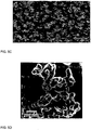
- the surface to be coated in this case a metal mesh, was held above a flame of a paraffin candle. Deposition of a soot layer immediately turned the metal black. Scanning electron microscopy revealed that the soot consists of carbon particles with a typical diameter of 30 - 40 nm, forming a loose, fractal-like network ( Fig. 5B ). A water drop gently deposited on the surface shows a contact angle above 160° and rolls off easily, proving the surface's superhydrophobicity. However, the structure is fragile as the particle-particle interactions are only physical and weak. When water rolls off the surface, the drop carries soot particles with it until almost all of the soot deposit is removed and the drop undergoes a wetting transition.
- the soot layer is coated with a silica shell making use of chemical vapour deposition (CVD) of tetraethoxysilane (TES) catalyzed by ammonia.
- CVD chemical vapour deposition
- TES tetraethoxysilane
- the soot-coated substrates were placed in a desiccator together with two open glass vessels containing tetraethoxysilane (TES) and ammonia, respectively. Similar to a Stöber reaction, silica is formed by hydrolysis and condensation of TES.
- the shell thickness can be tuned by the duration of CVD. After 24 h the particles are coated by a 20 ⁇ 5 nm thick silica shell ( Fig. 5C, D ).
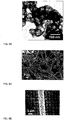
- Fig. 6 shows strings and fibers comprising particles with a silica shell and PVA (SEM micrographs) obtained by mixing an aqueous dispersion of PVA and silica colloids.
- strings and fibers can be immobilized on a desired carrier substrate surface by contacting the above or similar mixtures with the carrier substrate using any suitable method of the art, e.g. by means of electrospinning.
- the cell was placed into an air tight gas box.
- This gas box was equipped with two valves for in-flowing and out-flowing gas, connection tubes for in-flowing and out-flowing liquid and an oxygen partial pressure sensor.
- the gas box was flushed with a constant N 2 stream for 2 hours, until no more oxygen could be detected by the oxygen partial pressure sensor.
- Deoxygenated 1.2% blood/PBS solution (see above) was transferred to the reservoir under inert gas conditions. The total volume of the entire system was approx. 19 ml. Spectra were measured subsequently; the measurement of one spectrum took approximately 1 min 17 sec.
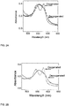
- Comparison of Fig. 2a with Fig. 2B (control) demonstrates that pumped blood/PBS was successfully oxygenated. The solution was pumped for more than 1 hour in a closed system without any leakage.
- Example 2 The same principal setup as described in Example 2 for the oxygenation of blood/PBS solutions was used. Again, it consisted of a pump, Tygon®-tubing, a flow cuvette, a reservoir and an air-tight gas box containing a superamphiphobic capillary/flow cell.
- the gas box was equipped with two valves for in-flowing and out-flowing gas, connection tubes for in-flowing and out-flowing liquid and an oxygen partial pressure sensor.
- sodium hydroxide solution with phenolphthalein was pumped through the capillary or flow cell.
- the capillary and the flow cell both partly consist of a superamphiphobic mesh, which was coated as described in Example 1 by deposition of paraffin candle soot, CVD of tetraethoxysilane und hydrophobization with trichlorofluorosilane. These meshes act as membranes and form a barrier to the outer gas atmosphere.
- the gas box was either filled with N 2 or CO 2 .
- the flow cell used was similar to or identical with the flow cell in Example 2.
- superamphiphobic capillaries ( Fig. 3C ) were also used.
- the manufacturing of these capillaries was slightly different from the manufacturing of plane superamphiphobic surfaces.
- a mesh piece with the size of about 3 cm to 6 cm x 1 cm is covered for ⁇ 45 s with candle soot from one side.
- the soot template is stabilized by chemical vapor deposition of tetraethoxysilane for 24 h in a desiccator (in analogy to the usual procedure).
- the samples were calcinated at 600°C for 2 hours. After calcination the meshes were shaped into capillaries by hand.
- the inner part of the tube was coated with the fractal silica network; the outer part of the tube had no coating.
- Shrinking tubes were heated using a fire-lighter.
- CO 2 will have contact to the pumped solution after a certain diffusion time.
- the pumped solution mainly consists of water and in the presence of water CO 2 is in equilibrium with carbonic acid (Equation 1).
- the carbonic acid will be neutralized by the dissolved sodium hydroxide. Once all sodium hydroxide is neutralized, phenolphthalein will turn colorless and the solution loses its characteristic UV-VIS absorption bands.
- Fig. 1B shows a significant drop in absorbance after replacing the N 2 gas atmosphere of the gas box with 3-4 liter CO 2 .
- the absorbance value drops to almost zero what corresponds to a total neutralization of sodium hydroxide in solution due to CO 2 diffusion through the superamphiphobic mesh. No liquid leakage could be observed.
- the timescale of gas-diffusion and neutralization of the actual sodium hydroxide solution passing through the flow cell took roughly about 1 min 12 sec and depends on various points:
- Superamphiphobic surfaces prepared as outlined below were brought into contact with human whole blood. After a predetermined time (typically a few hours), the whole blood was removed and the protein adhesion on the surfaces was quantified by the known Pierce Test.
- Stainless steel meshes were used for each experiment.
- the mesh width was 32 micrometers and the steel wires had a diameter of 28 micrometers.
- Five mesh pieces of 1.5 cm x 2.5 cm were cut, rinsed with water, ethanol and water, respectively.
- One mesh piece was used without any further modification as control.
- the other mesh pieces were attached to a steel mounting using a copper wire as shown in Fig. 4C.
- These suspended mesh pieces were coated with paraffin candle soot from both sides in analogy to the procedure described in Example 1. All steps (CVD of tetraethoxysilane, calcination at 600 °C, hydrophobization by CVD of trichlorofluorosilane) were carried out with suspended samples to prevent any possible damage of the coating due to contact with the surrounding environment. Some samples showed manufacturing defects and proved to be hydrophobic but not oleophobic. One of these superhydrophobic but not super-olephobic surfaces was examined as well as a comparative sample (hydrophob, oleophil). For comparison an untreated metal mesh was also investigated (control).
- the samples were immerged into whole human blood for 3 days at 21°C (FIG. 4c). After 3 days the samples were taken out and the upper part, which was not immersed, was cut off.
- the resulting meshes (approx. 1.5 x 1.5 cm) were cut into smaller pieces, weight and transferred to an Eppendorf cup for further protein quantification using the Pierce Test.
- the Pierce 660 nm Protein Assay (from Pierce Biotechnology, Rockford, IL, USA) is a colorimetric method to determine the total protein amount based on absorbance.
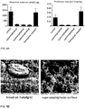
- Fig. 4A The results of the Pierce Test are shown in Fig. 4A . Results are given in total amount of protein for each sample in microgram ( ⁇ g) and, since the size of the samples varied slightly, in mass of proteins per milligram (mg) of weight mesh. The values for coated and uncoated meshes can be compared since coated and uncoated meshes are about equal in mass. A significantly reduced protein adhesion could be observed for all three super-amphiphobic meshes (below 0.01 mg protein per mg mesh). The untreated metal mesh showed about 0.04 mg protein per mg mesh and the hydrophob but oleophilic meshes showed about 0.07 mg protein per mg mesh.
- Superamphiphobic meshes with a size of approx. 1 cm x 1 cm were prepared as described above.
- the samples were introduced into a small sealable chamber with a water reservoir to provide air humidity. Blood drops were put onto the superamphiphobic meshes and the chamber was sealed with parafilm tape. The drops rested statically for 30 min, 4 h 24 min h and 48 h on the meshes and were carefully removed without damaging the surface after the specified times. For comparison, a drop was placed on an uncoated metal mesh. Samples were investigated using scanning electron microscopy.
Landscapes
- Chemical & Material Sciences (AREA)
- Chemical Kinetics & Catalysis (AREA)
- Health & Medical Sciences (AREA)
- Engineering & Computer Science (AREA)
- Emergency Medicine (AREA)
- Analytical Chemistry (AREA)
- General Chemical & Material Sciences (AREA)
- Oil, Petroleum & Natural Gas (AREA)
- Heart & Thoracic Surgery (AREA)
- Urology & Nephrology (AREA)
- Life Sciences & Earth Sciences (AREA)
- Inorganic Chemistry (AREA)
- Vascular Medicine (AREA)
- Anesthesiology (AREA)
- Biomedical Technology (AREA)
- Hematology (AREA)
- Dispersion Chemistry (AREA)
- Animal Behavior & Ethology (AREA)
- General Health & Medical Sciences (AREA)
- Public Health (AREA)
- Veterinary Medicine (AREA)
- External Artificial Organs (AREA)
- Separation Using Semi-Permeable Membranes (AREA)
Claims (17)
- Verfahren zur Überführung von Gasmolekülen aus einem gasförmigen Medium in ein flüssiges Medium oder umgekehrt, umfassend mindestens die folgenden Schritte:a) Bereitstellen eines flüssigen Mediums mit einer Oberflächenspannung Flüssigkeit/Luft im Bereich von 0,02 N/m bis 0,06 N/m,b) Bereitstellen eines gasförmigen Mediums,c) Bereitstellen einer Membran an einer Grenzfläche zwischen dem flüssigen Medium und dem gasförmigen Medium, wobei die Membran umfassti) ein Trägersubstrat mit durchgehenden Öffnungen, die einen mittleren Durchmesser im Bereich von 0,2 µm bis 200 µm, vorzugsweise im Bereich von 1 µm bis 50 µm, aufweisen, undii) eine poröse superamphiphobe Beschichtungsschicht mit Öffnungen, die einen mittleren Durchmesser im Bereich von 0,1 µm bis 10 µm aufweisen, wobei die Beschichtungsschicht eine Oberfläche, welche einen Kontaktwinkel von mindestens 150° bezüglich Wassertropfen einer Größe von 10 µl und auch einen Kontaktwinkel von mindestens 150° bezüglich Tropfen einer Größe von 10 µl von Flüssigkeiten mit einer Oberflächenspannung von nicht mehr als 0,06 N/m, insbesondere Ölen, Alkanen und aromatischen Verbindungen, aufweist, umfasst, welche auf mindestens der-jenigen Substratoberfläche, die dem flüssigen Medium gegenüber liegt, bereitgestellt wird,wobei entweder das flüssige Medium oder das gasförmige Medium, vorzugsweise das gasförmige Medium, mindestens ein zu überführendes Zielgas umfasst und die Membran für das mindestens eine zu überführende Gas permeabel ist und für das flüssige Medium aufgrund der bezüglich des flüssigen Mediums superamphiphoben Eigenschaften derjenigen Membranoberfläche, welche dem flüssigen Medium gegenüber liegt, nicht permeabel ist,d) Kontaktieren des gasförmigen Mediums mit dem flüssigen Medium über die superamphiphobe Schicht für eine ausreichende Zeit, um das flüssige oder gasförmige Zielmedium mit dem mindestens einen zu überführenden Gas anzureichern.
- Verfahren nach Anspruch 1, wobei Gasmoleküle von einem gasförmigen Medium in ein flüssiges Medium überführt werden.
- Verfahren nach Anspruch 1 oder 2, wobei das mindestens eine zu überführende Gas aus der Gruppe, welche Sauerstoff, Kohlendioxid, TiCl4, Stickstoffoxide, SO2, SO3, H2S, HCI, HCN, Ammoniak und Amine, Silane umfasst, ausgewählt ist.
- Vorrichtung zur Überführung von Gasmolekülen und/oder Partikeln aus einem gasförmigen Medium in ein flüssiges Medium oder umgekehrt, umfassend:a) ein flüssiges Medium mit einer Oberflächenspannung Flüssigkeit/Luft im Bereich von 0,02 N/m bis 0,06 N/m,b) ein gasförmiges Medium,c) eine Membran, die auf einer Grenzfläche zwischen dem flüssigen Medium und dem gasförmigen Medium bereitgestellt ist, wobei die Membran umfassti) ein Trägersubstrat mit durchgehenden Öffnungen, die einen mittleren Durchmesser im Bereich von 0,2 µm bis 200 µm, vorzugsweise im Bereich von 1 µm bis 50 µm, aufweisen, undii) eine poröse superamphiphobe Beschichtungsschicht mit Öffnungen, die einen mittleren Durchmesser im Bereich von 0,1 µm bis 10 µm aufweisen, wobei die Beschichtungsschicht eine Oberfläche, welche einen Kontaktwinkel von mindestens 150° bezüglich Wassertropfen einer Größe von 10 µl und auch einen Kontaktwinkel von mindestens 150° bezüglich Tropfen einer Größe von 10 µl von Flüssigkeiten mit einer Oberflächenspannung von nicht mehr als 0,06 N/m, insbesondere Ölen, Alkanen und aromatischen Verbindungen, aufweist, umfasst, welche mindestens auf der Substratoberfläche, die dem flüssigen Medium gegenüberliegt, bereitgestellt ist,wobei die Membran für mindestens ein Gas, das in dem flüssigen oder gasförmigen Medium, vorzugsweise in dem gasförmigen Medium, enthalten ist, permeabel ist und für das flüssige Medium aufgrund der bezüglich des flüssigen Mediums superamphiphoben Eigenschaften derjenigen Membranoberfläche, welche dem flüssigen Medium gegenüber liegt, nicht permeabel ist.
- Vorrichtung nach Anspruch 4, welche ein Gaswäscher oder der Oxygenator einer Herz-Lungen-Maschine oder eine Komponente davon ist.
- Verfahren nach einem der Ansprüche 1-3 oder Vorrichtung nach einem der Ansprüche 4-5, wobei die superamphiphobe Schicht Stränge, in Fasern eingebettete Partikel, Säulen, Aggregate oder eine fraktal-ähnliche Anordnung von Nano- oder Mikropartikeln mit einem mittleren Durchmesser im Bereich von 12 nm bis 2 µm, vorzugsweise 40 nm bis 200 nm, umfasst, wobei die Partikel entweder aus einem Material mit niedriger Oberflächenenergie bestehen oder mit einem Material mit niedriger Oberflächenenergie beschichtet sind, wobei das Material mit niedriger Oberflächenenergie dadurch gekennzeichnet ist, dass die Oberflächenspannung Luft/Substrat weniger als 0,03 N/m, vorzugsweise weniger als 0,02 N/m, beträgt.
- Verfahren oder Vorrichtung nach einem der Ansprüche 1-6, wobei das flüssige Medium aus der Gruppe ausgewählt ist, welche wässrige Medien, einschließlich Blut und wässrige Lösungen von Komponenten, die in der Lage sind, die Oberflächenspannung von Wasser auf 0,06 N/m oder weniger zu verringern, vorzugsweise ausgewählt aus der Gruppe, die Amine, oberflächenaktive Mittel, Lipide, Peptide, Proteine, Polyelektrolyte, DNA, Polymere, Block-Copolymere, Silane und funktionalisierte Partikel umfasst, organische Medien, die organische Lösungsmittel wie Alkane, Alkohole, aromatische Verbindungen und gegebenenfalls weitere Komponenten umfassen, ionische Flüssigkeiten und Mischungen davon umfasst.
- Verfahren oder Vorrichtung nach einem der Ansprüche 1-7, wobei das gasförmige Medium aus der Gruppe ausgewählt ist, welche Luft, Erdgas, ein Prozessgas oder ein industrielles Abgas umfasst.
- Verfahren oder Vorrichtung nach einem der Ansprüche 1-8, wobei das Trägersubstrat ein Sieb, vorzugsweise ein Metallsieb, Fasern, ein Textil, einen mikro- oder mesoporösen Schaum oder eine poröse dreidimensionale Struktur mit einer definierten Form, zum Beispiel eine poröse Kapillare, umfasst oder daraus besteht.
- Vorrichtung oder Verfahren nach Anspruch 9, wobei die poröse dreidimensionale Struktur mit einer definierten Gestalt einen länglichen röhrenförmigen Körper oder irgendeinen anderen longitudinal oder zweidimensional ausgedehnten Hohlkörper, der mindestens einen Hohlraum oder eine Kavität in dessen Inneren aufweist, umfasst oder daraus besteht.
- Verfahren oder Vorrichtung nach einem der Ansprüche 9-10, wobei das flüssige Medium in dem mindestens einen Hohlraum oder der mindestens einen Kavität im Inneren einer porösen dreidimensionalen Membranstruktur bereitgestellt ist und das gasförmige Medium auf der Außenseite der Struktur bereitgestellt ist, oder umgekehrt.
- Verfahren oder Vorrichtung nach einem der Ansprüche 1-11, wobei die Membran ein Trägersubstrat mit einer mikroporösen oder mesoporösen superamphiphoben Schicht, die auf mindestens einer Substratoberfläche bereitgestellt ist, umfasst, und wobei die poröse Schicht teilweise mit dem gasförmigen Medium gefüllt ist.
- Verfahren oder Vorrichtung nach einem der Ansprüche 1-12, wobei das flüssige Medium einen hydrostatischen Druck von mindestens 100 Pa, insbesondere mindestens 1000 Pa, auf die superamphiphobe Schicht der Membran ausübt.
- Verfahren nach einem der Ansprüche 1-3 und 6-13, wobei das flüssige Medium Blut umfasst oder daraus besteht, das gasförmige Medium Sauerstoff oder eine sauerstoffhaltige Gasmischung ist und das mindestens eine aus dem gasförmigen Medium zu überführende Gas Sauerstoff ist.
- Verfahren oder Vorrichtung nach einem der Ansprüche 1-14, wobei die Membran gebildet wird durch Bereitstellen eines Trägersubstrats mit durchgehenden Öffnungen, die einen mittleren Durchmesser im Bereich von 0,2 µm bis 200 µm, vorzugsweise im Bereich von 1 µm bis 50 µm, aufweisen, Abscheiden von Partikeln mit einem mittleren Durchmesser im Bereich von 12 nm bis 2 µm auf der Substratoberfläche, beispielsweise durch Sprühbeschichtung, Elektrospinning, Sedimentation oder durch Wachstum der Partikel auf der Trägeroberfläche, und optional, Beschichten der Partikel mit einer hydrophoben Deckschicht.
- Verfahren oder Vorrichtung nach Anspruch 15, wobei die Partikel Polymer-Partikel, Silica-Partikel oder mit einer Hülle beschichtete Partikel sind, wobei die Hülle eine Silica-Hülle, eine Hülle eines Materials wie AlO2, CeO2, SnO2, TiO2, andere Metalloxide, Ti{OCH(CH3)2}4 oder eine Hybridhülle, die 2 oder mehr Materialien, insbesondere aus den obigen ausgewählte, umfasst, sein kann, wobei die Silica-Partikel oder mit einer Hülle beschichtete Partikel ferner mit einer hydrophoben Deckschicht beschichtet sind.
- Verwendung des Verfahrens oder der Vorrichtung nach einem der Ansprüche 1-16 auf den Gebieten der Gaswäsche, insbesondere Aminwäsche, Rauchgasentschwefelung, Silaneinfang und der Medizin, insbesondere zur Oxygenierung von Blut.
Priority Applications (1)
| Application Number | Priority Date | Filing Date | Title |
|---|---|---|---|
| EP13814040.5A EP2934728B1 (de) | 2012-12-18 | 2013-12-18 | Verfahren und vorrichtung zur übertragung von gasmolekülen von einem gasförmigen medium in ein flüssiges medium oder umgekehrt |
Applications Claiming Priority (3)
| Application Number | Priority Date | Filing Date | Title |
|---|---|---|---|
| EP12008422.3A EP2745918A1 (de) | 2012-12-18 | 2012-12-18 | Verfahren und Vorrichtung zur Übertragung von Gasmolekülen von einem gasförmigen Medium in ein flüssiges Medium oder umgekehrt |
| EP13814040.5A EP2934728B1 (de) | 2012-12-18 | 2013-12-18 | Verfahren und vorrichtung zur übertragung von gasmolekülen von einem gasförmigen medium in ein flüssiges medium oder umgekehrt |
| PCT/EP2013/003833 WO2014095058A1 (en) | 2012-12-18 | 2013-12-18 | Method and device for transferring gas molecules from a gaseous medium into a liquid medium or vice versa |
Publications (2)
| Publication Number | Publication Date |
|---|---|
| EP2934728A1 EP2934728A1 (de) | 2015-10-28 |
| EP2934728B1 true EP2934728B1 (de) | 2017-05-31 |
Family
ID=47519785
Family Applications (2)
| Application Number | Title | Priority Date | Filing Date |
|---|---|---|---|
| EP12008422.3A Withdrawn EP2745918A1 (de) | 2012-12-18 | 2012-12-18 | Verfahren und Vorrichtung zur Übertragung von Gasmolekülen von einem gasförmigen Medium in ein flüssiges Medium oder umgekehrt |
| EP13814040.5A Active EP2934728B1 (de) | 2012-12-18 | 2013-12-18 | Verfahren und vorrichtung zur übertragung von gasmolekülen von einem gasförmigen medium in ein flüssiges medium oder umgekehrt |
Family Applications Before (1)
| Application Number | Title | Priority Date | Filing Date |
|---|---|---|---|
| EP12008422.3A Withdrawn EP2745918A1 (de) | 2012-12-18 | 2012-12-18 | Verfahren und Vorrichtung zur Übertragung von Gasmolekülen von einem gasförmigen Medium in ein flüssiges Medium oder umgekehrt |
Country Status (3)
| Country | Link |
|---|---|
| US (1) | US9901885B2 (de) |
| EP (2) | EP2745918A1 (de) |
| WO (1) | WO2014095058A1 (de) |
Cited By (1)
| Publication number | Priority date | Publication date | Assignee | Title |
|---|---|---|---|---|
| WO2025257034A1 (en) * | 2024-06-11 | 2025-12-18 | MAQUET CARDIOPULMONARY GmbH | Medical device comprising a gas transfer membrane |
Families Citing this family (13)
| Publication number | Priority date | Publication date | Assignee | Title |
|---|---|---|---|---|
| US9458022B2 (en) * | 2014-03-28 | 2016-10-04 | L'Air Liquide Société Anonyme Pour L'Étude Et L'Exploitation Des Procedes Georges Claude | Process and apparatus for separating NO2 from a CO2 and NO2—containing fluid |
| US10632426B2 (en) * | 2015-04-17 | 2020-04-28 | Georgia Tech Research Corporation | Hollow fiber membranes for solubilizing a gas into a liquid, devices for same, and processes of same |
| EP3302764A1 (de) | 2015-06-08 | 2018-04-11 | Becton, Dickinson and Company | Filtrationszelle und verfahren zum filtern einer biologischen probe |
| WO2017040650A1 (en) | 2015-09-01 | 2017-03-09 | Becton, Dickinson And Company | Depth filtration device for separating specimen phases |
| US10493409B2 (en) | 2016-03-02 | 2019-12-03 | Becton, Dickinson And Company | Biological fluid separation device |
| US11905177B2 (en) * | 2018-05-07 | 2024-02-20 | Covestro Intellectual Property Gmbh & Co. Kg | Storage medium and method for separating, storing and transporting chlorine from chlorine-containing gases |
| CN111467933B (zh) * | 2019-01-23 | 2021-09-07 | 中国科学院过程工程研究所 | 一种多位点质子型离子液体复合膜选择性分离氨气的方法 |
| CN111068501B (zh) * | 2020-01-17 | 2023-10-20 | 珠海益佳生物科技有限公司 | 一种同时脱除硫化氢和氨气废气的吸收分解液、方法和装置 |
| CN111389245B (zh) * | 2020-04-17 | 2021-04-13 | 天津工业大学 | 一种单面超疏水聚合物纤维膜及其制备方法和应用 |
| DE102021100090B4 (de) | 2020-05-13 | 2023-08-10 | Drägerwerk AG & Co. KGaA | System zu einer Bereitstellung von Gasen oder Gasgemischen mit Zuführung von Substanzen |
| CN111644067A (zh) * | 2020-06-17 | 2020-09-11 | 东北电力大学 | 一种纳米微柱超双疏复合膜的制备方法 |
| CN111991849A (zh) * | 2020-07-15 | 2020-11-27 | 广东工业大学 | 一种快速构筑超疏水/超亲油的油水分离材料及其制备方法和应用 |
| CN114539855B (zh) * | 2022-03-09 | 2023-01-10 | 中国科学院兰州化学物理研究所 | 一种“海-岛”结构稳定超双疏涂层的制备方法 |
Family Cites Families (5)
| Publication number | Priority date | Publication date | Assignee | Title |
|---|---|---|---|---|
| US3413095A (en) * | 1965-06-14 | 1968-11-26 | Mogens L. Bramson | Membrane oxygenator |
| JPS6244961B2 (de) * | 1979-08-21 | 1987-09-24 | Nikorai Sutepanobitsuchi Ridorenko | |
| US6967003B2 (en) * | 2001-09-28 | 2005-11-22 | Dainippon Ink And Chemicals, Inc. | Artificial lung of membrane type |
| JP4046146B1 (ja) * | 2007-04-23 | 2008-02-13 | 東洋紡績株式会社 | 中空糸膜型人工肺および処理方法 |
| FI122230B (fi) | 2009-07-02 | 2011-10-31 | Aalto Korkeakoulusaeaetioe | Nestettä hylkivä materiaali |
-
2012
- 2012-12-18 EP EP12008422.3A patent/EP2745918A1/de not_active Withdrawn
-
2013
- 2013-12-18 EP EP13814040.5A patent/EP2934728B1/de active Active
- 2013-12-18 US US14/653,428 patent/US9901885B2/en not_active Expired - Fee Related
- 2013-12-18 WO PCT/EP2013/003833 patent/WO2014095058A1/en not_active Ceased
Cited By (1)
| Publication number | Priority date | Publication date | Assignee | Title |
|---|---|---|---|---|
| WO2025257034A1 (en) * | 2024-06-11 | 2025-12-18 | MAQUET CARDIOPULMONARY GmbH | Medical device comprising a gas transfer membrane |
Also Published As
| Publication number | Publication date |
|---|---|
| US9901885B2 (en) | 2018-02-27 |
| US20160045875A1 (en) | 2016-02-18 |
| EP2934728A1 (de) | 2015-10-28 |
| WO2014095058A1 (en) | 2014-06-26 |
| EP2745918A1 (de) | 2014-06-25 |
Similar Documents
| Publication | Publication Date | Title |
|---|---|---|
| US9901885B2 (en) | Method and device for transferring gas molecules from a gaseous medium into a liquid medium or vice versa | |
| EP2228126B1 (de) | Verwendung und Anwendungen einer Hohlfasermembran | |
| US4268279A (en) | Gas transfer process with hollow fiber membrane | |
| Paven et al. | Super liquid-repellent gas membranes for carbon dioxide capture and heart–lung machines | |
| CA1323271C (en) | Membrane-type artificial lung and method of using it | |
| US20170037356A1 (en) | Biologically-relevant selective enclosures for promoting growth and vascularization | |
| CA2290593C (en) | Non-porous gas permeable membrane | |
| US12582939B2 (en) | Porous liquid, self-replenishing porous liquid and methods of making and using the same | |
| GB2025256A (en) | A Gas Transfer Process Using a Hollow Fiber Membrane | |
| JP2005516764A (ja) | ヘイラー膜 | |
| Mansourizadeh et al. | Blend polyvinylidene fluoride/surface modifying macromolecule hollow fiber membrane contactors for CO2 absorption | |
| CN1301149C (zh) | 具有整体非对称结构的聚烯烃膜及其制备方法 | |
| WO2011091074A2 (en) | Nanoporous membranes, devices, and methods for respiratory gas exchange | |
| WO2018201098A2 (en) | Enzymatically active high-flux selectively gas-permeable membranes for enhanced oil recovery and carbon capture | |
| WO2010086630A1 (en) | Gas separation membrane | |
| JP2006239636A (ja) | ファウリング防止材及び該ファウリング防止材で表面処理された分離膜 | |
| Mamah et al. | Advancement in modification of polyvinylindene fluoride hollow fiber membrane contactors for CO2 capture | |
| KR20190096347A (ko) | 복합 반투막 및 그의 제조 방법 | |
| Zhang et al. | Bioinspired hierarchical colloidal crystal paper with Janus wettability for oil/water separation and heavy metal ion removal | |
| CN119746660A (zh) | 一种表面生长cof层的渗透膜及其制备方法和应用 | |
| CA2949948A1 (en) | Methods of forming a polymer layer on a polymer surface | |
| Fukuda et al. | 3D porous structure imaging of membranes for medical devices using scanning probe microscopy and electron microscopy: from membrane science points of view | |
| FR3057581A1 (fr) | Procede de revetement de materiaux textiles | |
| EP0164468A2 (de) | Poröse Membran | |
| RU2835016C2 (ru) | Сорбционно-бактерицидный материал из нетканого полимерного волокнистого материала, способ диализа жидких сред |
Legal Events
| Date | Code | Title | Description |
|---|---|---|---|
| PUAI | Public reference made under article 153(3) epc to a published international application that has entered the european phase |
Free format text: ORIGINAL CODE: 0009012 |
|
| 17P | Request for examination filed |
Effective date: 20150601 |
|
| AK | Designated contracting states |
Kind code of ref document: A1 Designated state(s): AL AT BE BG CH CY CZ DE DK EE ES FI FR GB GR HR HU IE IS IT LI LT LU LV MC MK MT NL NO PL PT RO RS SE SI SK SM TR |
|
| AX | Request for extension of the european patent |
Extension state: BA ME |
|
| RIN1 | Information on inventor provided before grant (corrected) |
Inventor name: BUTT, HANS-JUERGEN Inventor name: MAMMEN, LENA Inventor name: PAVEN, MAXIME Inventor name: VOLLMER, DORIS Inventor name: PAPADOPOULOS, PERIKLIS Inventor name: DENG, XU |
|
| DAX | Request for extension of the european patent (deleted) | ||
| GRAP | Despatch of communication of intention to grant a patent |
Free format text: ORIGINAL CODE: EPIDOSNIGR1 |
|
| STAA | Information on the status of an ep patent application or granted ep patent |
Free format text: STATUS: GRANT OF PATENT IS INTENDED |
|
| INTG | Intention to grant announced |
Effective date: 20170201 |
|
| GRAS | Grant fee paid |
Free format text: ORIGINAL CODE: EPIDOSNIGR3 |
|
| GRAA | (expected) grant |
Free format text: ORIGINAL CODE: 0009210 |
|
| STAA | Information on the status of an ep patent application or granted ep patent |
Free format text: STATUS: THE PATENT HAS BEEN GRANTED |
|
| AK | Designated contracting states |
Kind code of ref document: B1 Designated state(s): AL AT BE BG CH CY CZ DE DK EE ES FI FR GB GR HR HU IE IS IT LI LT LU LV MC MK MT NL NO PL PT RO RS SE SI SK SM TR |
|
| REG | Reference to a national code |
Ref country code: CH Ref legal event code: EP Ref country code: GB Ref legal event code: FG4D |
|
| REG | Reference to a national code |
Ref country code: AT Ref legal event code: REF Ref document number: 896933 Country of ref document: AT Kind code of ref document: T Effective date: 20170615 |
|
| REG | Reference to a national code |
Ref country code: IE Ref legal event code: FG4D |
|
| REG | Reference to a national code |
Ref country code: DE Ref legal event code: R096 Ref document number: 602013021812 Country of ref document: DE |
|
| REG | Reference to a national code |
Ref country code: NL Ref legal event code: MP Effective date: 20170531 |
|
| REG | Reference to a national code |
Ref country code: LT Ref legal event code: MG4D |
|
| REG | Reference to a national code |
Ref country code: AT Ref legal event code: MK05 Ref document number: 896933 Country of ref document: AT Kind code of ref document: T Effective date: 20170531 |
|
| PG25 | Lapsed in a contracting state [announced via postgrant information from national office to epo] |
Ref country code: HR Free format text: LAPSE BECAUSE OF FAILURE TO SUBMIT A TRANSLATION OF THE DESCRIPTION OR TO PAY THE FEE WITHIN THE PRESCRIBED TIME-LIMIT Effective date: 20170531 Ref country code: GR Free format text: LAPSE BECAUSE OF FAILURE TO SUBMIT A TRANSLATION OF THE DESCRIPTION OR TO PAY THE FEE WITHIN THE PRESCRIBED TIME-LIMIT Effective date: 20170901 Ref country code: NO Free format text: LAPSE BECAUSE OF FAILURE TO SUBMIT A TRANSLATION OF THE DESCRIPTION OR TO PAY THE FEE WITHIN THE PRESCRIBED TIME-LIMIT Effective date: 20170831 Ref country code: ES Free format text: LAPSE BECAUSE OF FAILURE TO SUBMIT A TRANSLATION OF THE DESCRIPTION OR TO PAY THE FEE WITHIN THE PRESCRIBED TIME-LIMIT Effective date: 20170531 Ref country code: FI Free format text: LAPSE BECAUSE OF FAILURE TO SUBMIT A TRANSLATION OF THE DESCRIPTION OR TO PAY THE FEE WITHIN THE PRESCRIBED TIME-LIMIT Effective date: 20170531 Ref country code: AT Free format text: LAPSE BECAUSE OF FAILURE TO SUBMIT A TRANSLATION OF THE DESCRIPTION OR TO PAY THE FEE WITHIN THE PRESCRIBED TIME-LIMIT Effective date: 20170531 Ref country code: LT Free format text: LAPSE BECAUSE OF FAILURE TO SUBMIT A TRANSLATION OF THE DESCRIPTION OR TO PAY THE FEE WITHIN THE PRESCRIBED TIME-LIMIT Effective date: 20170531 |
|
| PG25 | Lapsed in a contracting state [announced via postgrant information from national office to epo] |
Ref country code: NL Free format text: LAPSE BECAUSE OF FAILURE TO SUBMIT A TRANSLATION OF THE DESCRIPTION OR TO PAY THE FEE WITHIN THE PRESCRIBED TIME-LIMIT Effective date: 20170531 Ref country code: BG Free format text: LAPSE BECAUSE OF FAILURE TO SUBMIT A TRANSLATION OF THE DESCRIPTION OR TO PAY THE FEE WITHIN THE PRESCRIBED TIME-LIMIT Effective date: 20170831 Ref country code: LV Free format text: LAPSE BECAUSE OF FAILURE TO SUBMIT A TRANSLATION OF THE DESCRIPTION OR TO PAY THE FEE WITHIN THE PRESCRIBED TIME-LIMIT Effective date: 20170531 Ref country code: SE Free format text: LAPSE BECAUSE OF FAILURE TO SUBMIT A TRANSLATION OF THE DESCRIPTION OR TO PAY THE FEE WITHIN THE PRESCRIBED TIME-LIMIT Effective date: 20170531 Ref country code: IS Free format text: LAPSE BECAUSE OF FAILURE TO SUBMIT A TRANSLATION OF THE DESCRIPTION OR TO PAY THE FEE WITHIN THE PRESCRIBED TIME-LIMIT Effective date: 20170930 Ref country code: RS Free format text: LAPSE BECAUSE OF FAILURE TO SUBMIT A TRANSLATION OF THE DESCRIPTION OR TO PAY THE FEE WITHIN THE PRESCRIBED TIME-LIMIT Effective date: 20170531 |
|
| REG | Reference to a national code |
Ref country code: FR Ref legal event code: PLFP Year of fee payment: 5 |
|
| PG25 | Lapsed in a contracting state [announced via postgrant information from national office to epo] |
Ref country code: CZ Free format text: LAPSE BECAUSE OF FAILURE TO SUBMIT A TRANSLATION OF THE DESCRIPTION OR TO PAY THE FEE WITHIN THE PRESCRIBED TIME-LIMIT Effective date: 20170531 Ref country code: RO Free format text: LAPSE BECAUSE OF FAILURE TO SUBMIT A TRANSLATION OF THE DESCRIPTION OR TO PAY THE FEE WITHIN THE PRESCRIBED TIME-LIMIT Effective date: 20170531 Ref country code: SK Free format text: LAPSE BECAUSE OF FAILURE TO SUBMIT A TRANSLATION OF THE DESCRIPTION OR TO PAY THE FEE WITHIN THE PRESCRIBED TIME-LIMIT Effective date: 20170531 Ref country code: DK Free format text: LAPSE BECAUSE OF FAILURE TO SUBMIT A TRANSLATION OF THE DESCRIPTION OR TO PAY THE FEE WITHIN THE PRESCRIBED TIME-LIMIT Effective date: 20170531 Ref country code: EE Free format text: LAPSE BECAUSE OF FAILURE TO SUBMIT A TRANSLATION OF THE DESCRIPTION OR TO PAY THE FEE WITHIN THE PRESCRIBED TIME-LIMIT Effective date: 20170531 |
|
| PG25 | Lapsed in a contracting state [announced via postgrant information from national office to epo] |
Ref country code: IT Free format text: LAPSE BECAUSE OF FAILURE TO SUBMIT A TRANSLATION OF THE DESCRIPTION OR TO PAY THE FEE WITHIN THE PRESCRIBED TIME-LIMIT Effective date: 20170531 Ref country code: SM Free format text: LAPSE BECAUSE OF FAILURE TO SUBMIT A TRANSLATION OF THE DESCRIPTION OR TO PAY THE FEE WITHIN THE PRESCRIBED TIME-LIMIT Effective date: 20170531 Ref country code: PL Free format text: LAPSE BECAUSE OF FAILURE TO SUBMIT A TRANSLATION OF THE DESCRIPTION OR TO PAY THE FEE WITHIN THE PRESCRIBED TIME-LIMIT Effective date: 20170531 |
|
| REG | Reference to a national code |
Ref country code: DE Ref legal event code: R097 Ref document number: 602013021812 Country of ref document: DE |
|
| PLBE | No opposition filed within time limit |
Free format text: ORIGINAL CODE: 0009261 |
|
| STAA | Information on the status of an ep patent application or granted ep patent |
Free format text: STATUS: NO OPPOSITION FILED WITHIN TIME LIMIT |
|
| 26N | No opposition filed |
Effective date: 20180301 |
|
| PG25 | Lapsed in a contracting state [announced via postgrant information from national office to epo] |
Ref country code: SI Free format text: LAPSE BECAUSE OF FAILURE TO SUBMIT A TRANSLATION OF THE DESCRIPTION OR TO PAY THE FEE WITHIN THE PRESCRIBED TIME-LIMIT Effective date: 20170531 |
|
| REG | Reference to a national code |
Ref country code: CH Ref legal event code: PL |
|
| REG | Reference to a national code |
Ref country code: IE Ref legal event code: MM4A |
|
| PG25 | Lapsed in a contracting state [announced via postgrant information from national office to epo] |
Ref country code: MT Free format text: LAPSE BECAUSE OF NON-PAYMENT OF DUE FEES Effective date: 20171218 Ref country code: LU Free format text: LAPSE BECAUSE OF NON-PAYMENT OF DUE FEES Effective date: 20171218 |
|
| REG | Reference to a national code |
Ref country code: BE Ref legal event code: MM Effective date: 20171231 |
|
| PG25 | Lapsed in a contracting state [announced via postgrant information from national office to epo] |
Ref country code: IE Free format text: LAPSE BECAUSE OF NON-PAYMENT OF DUE FEES Effective date: 20171218 |
|
| PG25 | Lapsed in a contracting state [announced via postgrant information from national office to epo] |
Ref country code: LI Free format text: LAPSE BECAUSE OF NON-PAYMENT OF DUE FEES Effective date: 20171231 Ref country code: CH Free format text: LAPSE BECAUSE OF NON-PAYMENT OF DUE FEES Effective date: 20171231 Ref country code: BE Free format text: LAPSE BECAUSE OF NON-PAYMENT OF DUE FEES Effective date: 20171231 |
|
| PG25 | Lapsed in a contracting state [announced via postgrant information from national office to epo] |
Ref country code: HU Free format text: LAPSE BECAUSE OF FAILURE TO SUBMIT A TRANSLATION OF THE DESCRIPTION OR TO PAY THE FEE WITHIN THE PRESCRIBED TIME-LIMIT; INVALID AB INITIO Effective date: 20131218 Ref country code: MC Free format text: LAPSE BECAUSE OF FAILURE TO SUBMIT A TRANSLATION OF THE DESCRIPTION OR TO PAY THE FEE WITHIN THE PRESCRIBED TIME-LIMIT Effective date: 20170531 |
|
| PG25 | Lapsed in a contracting state [announced via postgrant information from national office to epo] |
Ref country code: CY Free format text: LAPSE BECAUSE OF FAILURE TO SUBMIT A TRANSLATION OF THE DESCRIPTION OR TO PAY THE FEE WITHIN THE PRESCRIBED TIME-LIMIT Effective date: 20170531 |
|
| PG25 | Lapsed in a contracting state [announced via postgrant information from national office to epo] |
Ref country code: MK Free format text: LAPSE BECAUSE OF FAILURE TO SUBMIT A TRANSLATION OF THE DESCRIPTION OR TO PAY THE FEE WITHIN THE PRESCRIBED TIME-LIMIT Effective date: 20170531 |
|
| PG25 | Lapsed in a contracting state [announced via postgrant information from national office to epo] |
Ref country code: TR Free format text: LAPSE BECAUSE OF FAILURE TO SUBMIT A TRANSLATION OF THE DESCRIPTION OR TO PAY THE FEE WITHIN THE PRESCRIBED TIME-LIMIT Effective date: 20170531 |
|
| PG25 | Lapsed in a contracting state [announced via postgrant information from national office to epo] |
Ref country code: PT Free format text: LAPSE BECAUSE OF FAILURE TO SUBMIT A TRANSLATION OF THE DESCRIPTION OR TO PAY THE FEE WITHIN THE PRESCRIBED TIME-LIMIT Effective date: 20170531 |
|
| PG25 | Lapsed in a contracting state [announced via postgrant information from national office to epo] |
Ref country code: AL Free format text: LAPSE BECAUSE OF FAILURE TO SUBMIT A TRANSLATION OF THE DESCRIPTION OR TO PAY THE FEE WITHIN THE PRESCRIBED TIME-LIMIT Effective date: 20170531 |
|
| PGFP | Annual fee paid to national office [announced via postgrant information from national office to epo] |
Ref country code: DE Payment date: 20251211 Year of fee payment: 13 |
|
| PGFP | Annual fee paid to national office [announced via postgrant information from national office to epo] |
Ref country code: GB Payment date: 20251218 Year of fee payment: 13 |
|
| PGFP | Annual fee paid to national office [announced via postgrant information from national office to epo] |
Ref country code: FR Payment date: 20251217 Year of fee payment: 13 |