EP2933503B1 - Betriebsverfahren für eine Druckluftaufbereitungseinrichtung für ein Nutzfahrzeug - Google Patents
Betriebsverfahren für eine Druckluftaufbereitungseinrichtung für ein Nutzfahrzeug Download PDFInfo
- Publication number
- EP2933503B1 EP2933503B1 EP15000119.6A EP15000119A EP2933503B1 EP 2933503 B1 EP2933503 B1 EP 2933503B1 EP 15000119 A EP15000119 A EP 15000119A EP 2933503 B1 EP2933503 B1 EP 2933503B1
- Authority
- EP
- European Patent Office
- Prior art keywords
- valve
- compressed air
- air
- operating method
- processing device
- Prior art date
- Legal status (The legal status is an assumption and is not a legal conclusion. Google has not performed a legal analysis and makes no representation as to the accuracy of the status listed.)
- Active
Links
- 238000011017 operating method Methods 0.000 title claims description 18
- 238000012545 processing Methods 0.000 claims description 21
- 238000007605 air drying Methods 0.000 claims description 7
- 238000002360 preparation method Methods 0.000 claims description 6
- 230000000903 blocking effect Effects 0.000 claims description 3
- 238000004378 air conditioning Methods 0.000 description 5
- 230000006835 compression Effects 0.000 description 4
- 238000007906 compression Methods 0.000 description 4
- 238000011161 development Methods 0.000 description 2
- 230000018109 developmental process Effects 0.000 description 2
- 230000008929 regeneration Effects 0.000 description 2
- 238000011069 regeneration method Methods 0.000 description 2
- 238000006243 chemical reaction Methods 0.000 description 1
- 230000001419 dependent effect Effects 0.000 description 1
- 239000002274 desiccant Substances 0.000 description 1
- 238000007599 discharging Methods 0.000 description 1
- 239000007789 gas Substances 0.000 description 1
- 238000000034 method Methods 0.000 description 1
- 238000012986 modification Methods 0.000 description 1
- 230000004048 modification Effects 0.000 description 1
Images


Classifications
-
- F—MECHANICAL ENGINEERING; LIGHTING; HEATING; WEAPONS; BLASTING
- F15—FLUID-PRESSURE ACTUATORS; HYDRAULICS OR PNEUMATICS IN GENERAL
- F15B—SYSTEMS ACTING BY MEANS OF FLUIDS IN GENERAL; FLUID-PRESSURE ACTUATORS, e.g. SERVOMOTORS; DETAILS OF FLUID-PRESSURE SYSTEMS, NOT OTHERWISE PROVIDED FOR
- F15B11/00—Servomotor systems without provision for follow-up action; Circuits therefor
- F15B11/06—Servomotor systems without provision for follow-up action; Circuits therefor involving features specific to the use of a compressible medium, e.g. air, steam
-
- F—MECHANICAL ENGINEERING; LIGHTING; HEATING; WEAPONS; BLASTING
- F15—FLUID-PRESSURE ACTUATORS; HYDRAULICS OR PNEUMATICS IN GENERAL
- F15B—SYSTEMS ACTING BY MEANS OF FLUIDS IN GENERAL; FLUID-PRESSURE ACTUATORS, e.g. SERVOMOTORS; DETAILS OF FLUID-PRESSURE SYSTEMS, NOT OTHERWISE PROVIDED FOR
- F15B21/00—Common features of fluid actuator systems; Fluid-pressure actuator systems or details thereof, not covered by any other group of this subclass
- F15B21/04—Special measures taken in connection with the properties of the fluid
-
- B—PERFORMING OPERATIONS; TRANSPORTING
- B60—VEHICLES IN GENERAL
- B60R—VEHICLES, VEHICLE FITTINGS, OR VEHICLE PARTS, NOT OTHERWISE PROVIDED FOR
- B60R16/00—Electric or fluid circuits specially adapted for vehicles and not otherwise provided for; Arrangement of elements of electric or fluid circuits specially adapted for vehicles and not otherwise provided for
- B60R16/08—Electric or fluid circuits specially adapted for vehicles and not otherwise provided for; Arrangement of elements of electric or fluid circuits specially adapted for vehicles and not otherwise provided for fluid
-
- B—PERFORMING OPERATIONS; TRANSPORTING
- B60—VEHICLES IN GENERAL
- B60T—VEHICLE BRAKE CONTROL SYSTEMS OR PARTS THEREOF; BRAKE CONTROL SYSTEMS OR PARTS THEREOF, IN GENERAL; ARRANGEMENT OF BRAKING ELEMENTS ON VEHICLES IN GENERAL; PORTABLE DEVICES FOR PREVENTING UNWANTED MOVEMENT OF VEHICLES; VEHICLE MODIFICATIONS TO FACILITATE COOLING OF BRAKES
- B60T17/00—Component parts, details, or accessories of power brake systems not covered by groups B60T8/00, B60T13/00 or B60T15/00, or presenting other characteristic features
- B60T17/02—Arrangements of pumps or compressors, or control devices therefor
-
- F—MECHANICAL ENGINEERING; LIGHTING; HEATING; WEAPONS; BLASTING
- F15—FLUID-PRESSURE ACTUATORS; HYDRAULICS OR PNEUMATICS IN GENERAL
- F15B—SYSTEMS ACTING BY MEANS OF FLUIDS IN GENERAL; FLUID-PRESSURE ACTUATORS, e.g. SERVOMOTORS; DETAILS OF FLUID-PRESSURE SYSTEMS, NOT OTHERWISE PROVIDED FOR
- F15B21/00—Common features of fluid actuator systems; Fluid-pressure actuator systems or details thereof, not covered by any other group of this subclass
- F15B21/04—Special measures taken in connection with the properties of the fluid
- F15B21/048—Arrangements for compressed air preparation, e.g. comprising air driers, air condensers, filters, lubricators or pressure regulators
Definitions
- the invention relates to an operating method for a particular electronic compressed air processing device for a commercial vehicle, for. B. a truck or a bus.
- the invention also relates to a compressed air processing device configured to carry out the method of operation.
- the DE 10 2011 083 614 A1 which discloses a dryer circuit for a pneumatic control device of a vehicle comprising an air dryer and a first compressor, wherein the first compressor is configured to compress system air present in the pneumatic control device, the air dryer, the first compressor and the first compressor Compressor connectable subsystems of the pneumatic control device are arranged so that in the operating mode of a closed air supply between the components of one of the subsystems using the first compressor transported air is conveyed, bypassing the air dryer.
- the valve switches in the air compressor cylinder head, which intake and compression chamber are interconnected.
- the air compressor is in energy-saving mode, the reduced flow rate is vented through the drain valve to the outside. If, however, the system pressure falls below a defined minimum pressure, the drain valve must be closed. This slowly increases the pressure in the delivery line.
- about 2 liters of volume have to be filled, namely the delivery line between the air compressor and the air treatment unit and a desiccant cartridge of the air treatment unit.
- the air compressor promotes only the reduced amount of air and above about 2 bar in the delivery line again the full amount of air when the valve in the air compressor cylinder head closes the connection between the intake and compression chamber.
- An object of the invention is to provide an operating method for a suitably electronic compressed air treatment device for a commercial vehicle, by means of which in particular short deceleration phases for energy or energy conversion can be exploited, in particular by means of which from an idle / energy-saving phase, the pressure in a delivery line faster can be constructed, for. B. over a limiting pressure of preferably about 2 bar.
- the invention provides an operating method for a particularly electronic compressed air treatment device for connecting to an air compressor device automatically switched into an idling state by means of compressed air from the compressed air processing device (eg compressor with so-called automatic idling system (SLS)) and with a compressed air system.
- the compressed air processing device eg compressor with so-called automatic idling system (SLS)
- SLS automatic idling system
- the compressed air processing device comprises a conveying device connectable to the air compressor device (eg a delivery line), a first valve, a second valve, a third valve and a fourth valve.
- a conveying device connectable to the air compressor device (eg a delivery line), a first valve, a second valve, a third valve and a fourth valve.
- a delivery phase eg work phase
- the first valve and the third valve are switched to a locked state and the second valve is switched to an open state.
- air can be conducted from the compressed air system via the second valve and bypassing the fourth valve back to the conveyor, in particular to be able to build the air pressure in the conveyor from the idle phase, starting from a non-pressurized conveyor.
- energy from coasting phases eg downhill
- even short deceleration phases of z. B. under 30 seconds, less than 15 seconds or even less than 5 seconds, converted into compressed air and stored in the compressed air system.
- the connecting pipe preferably branches off from a line section connecting the second valve to the third valve and opens between the fourth valve and the air conditioning or air drying device.
- the connecting line may have a throttle valve, which represents a fifth valve of the compressed air processing device.
- the second valve can be switched from the idle phase of a locked state to an open state and expedient always and only in a locked state when z. B. by means of a pressure sensor, a pressure increase in a line section between the second valve and the compressed air system is detected.
- the first valve and / or the second valve is a preferably electrically switchable switching valve, preferably a solenoid valve.
- air from the compressed air system acts on the third valve via the first valve when the first valve is opened to switch the third valve.
- the third valve is expediently connected via a line section to the first valve in order to be switched by means of compressed air from the compressed air system and / or from the first valve.
- air from the compressed air system may act on the third valve via the second valve when the second valve is opened to switch the third valve.
- the third valve is expediently connected via a line section to the second valve in order to be switched by means of compressed air from the compressed air system and / or from the second valve.
- the third valve is therefore suitably controllable both via the first valve and via the second valve by means of compressed air from the compressed air system.
- the third valve is preferably an air discharge valve for selectively blocking or discharging air from the conveyor and / or a compressed air switchable valve, in particular compressed air switchable via air from the first valve and the second valve.
- the fourth valve is preferably a check valve.
- the fourth valve may, for. B. allow a passage of air from the conveyor towards compressed air system, however, prevent a passage of air from the compressed air system in the direction of conveyor.
- the compressed air processing device may include a pressure sensor for detecting the air pressure between the second valve and the compressed air system.
- the second valve can be switched as a function of the values detected by means of the pressure sensor.
- air in the context of the invention is to be understood broadly and may preferably also include other gases.
- the feature “idle phase” may include an “energy saving phase” and the feature “promotion phase” may include a “work phase”.
- the invention is not limited to an operating method, but also includes a compressed air processing device configured to carry out the operating method as described herein.
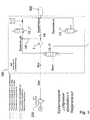
- FIG. 1 shows an electronic compressed air processing device 100 according to an embodiment of the invention.
- the compressed air preparation device 100 is used for connecting on the one hand to an air compressor device 200 which can automatically be switched into an idling state by means of compressed air from the compressed air processing device 100 (eg air compressor with so-called automatic idling system SLS, air compressor can switch to idling automatically) and to a compressed air system 300 for connection on the other hand
- the compressed air processing device 100 and the air compressor device 200 are connected to one another via a conveying device (conveying line) FE.
- the conveyor FE leads via an input 1 in the compressed air processing device 100th
- the compressed air treatment device 100 comprises a first valve V1 (electrically switchable solenoid valve), a second valve V2 (electrically switchable solenoid valve), a third valve V3 (air release valve), a fourth valve V4 (check valve) and a fifth valve V5 (throttle valve).
- the third valve V3 is used for compressed air-controlled, selective blocking or outputting of air from the conveyor FE.
- the air to be dispensed by means of the third valve V3 can be led out of the compressed air processing device 100 via an outlet 3.
- the compressed air treatment device 100 comprises an air treatment device T, z.
- an air-drying device for regeneration in particular dry air from the compressed air system 300th
- the third valve V3 is connected via a line section 1-3 with the first valve V1 in connection to be switched by means of compressed air from the first valve V1. Air from the compressed air system 300 may act on the third valve V3 via the first valve V1 when the first valve V1 is opened to switch the third valve V3.
- the third valve V3 is connected via a line section 2-3 to the second valve V2 in order to be switched by means of compressed air from the second valve V2. Air from the compressed air system 300 may act on the third valve V3 via the second valve V2 when the second valve V2 is opened to switch the third valve V3.
- connection line VL branches off from the line section 2-3 and terminates between the fourth valve V4 and the air treatment device T.
- the connection line VL comprises the fifth valve V5.
- FIG. 1 switch the system state "air compressor 200 quickly from the idle phase into the delivery phase”
- FIG. 2 the system status "Promote”
- FIG. 3 the system state “Air compressor 200 off plus regenerate”
- Figure 4 shows the system state “Air compressor 200 off” shows.
- the first valve V1 and the third valve V3 are switched to a locked state "0" and the second valve V2 is switched to an open state "1" (FIG. FIG. 1 ), so that air from the compressed air system 300 via the second valve V2 and bypassing the fourth valve V4 - that is parallel to the fourth valve V4 - is fed back to the conveyor FE, whereby the initially pressureless conveyor FE is pressurized.
- the pressure in the conveyor FE can be built faster to better utilize the (low-energy) compressed air delivery during, in particular, short coasting phases of the commercial vehicle. Even shear phases of z. B.
- the second valve V2 is opened when the third valve V3 is open, whereby dry air from the compressed air system 300 parallel to the fourth valve V4 via the connecting line VL and the fifth valve V5 through the air conditioning Device T for the regeneration of the same can flow ( FIG. 3 ).
- the system thus provides for feeding air back from the compressed air system 300 into the conveyor FE.
- This can be realized just by the fact that when the third valve 3 is closed, the second valve V2 is opened, so that air flows into the conveyor FE and the pressure faster over a limiting pressure of z. B. usually about 2 bar can rise.
- the air compressor device 200 can again promote the full amount of air faster and the pressure in the conveyor FE can exceed the system pressure faster.
- the energy freely available in a coasting phase can be stored more quickly in the compressed air system 300, even if the coasting phase is relatively short.
- the system thus makes it possible to utilize, in particular, short deceleration phases to obtain (recover) freely available energy within the deceleration phases or to convert freely available energy within the deceleration phases in compressed air and subsequent storage in the compressed air system 300
- Compressed air system 300 in the conveyor FE the air compressor device 200 can be more quickly offset from an idle phase in a (full) delivery phase.
- the second valve V2 is switched from the idle phase of a locked state "0" in an open state "1" and indeed expedient and only when between the compressed air system 300 and the second valve V2, a pressure increase by means of a pressure sensor S is sensed ,
Landscapes
- Engineering & Computer Science (AREA)
- Mechanical Engineering (AREA)
- Physics & Mathematics (AREA)
- Fluid Mechanics (AREA)
- General Engineering & Computer Science (AREA)
- Chemical & Material Sciences (AREA)
- Analytical Chemistry (AREA)
- Transportation (AREA)
- Valves And Accessory Devices For Braking Systems (AREA)
- Control Of Positive-Displacement Pumps (AREA)
- Fluid-Pressure Circuits (AREA)
- Compressors, Vaccum Pumps And Other Relevant Systems (AREA)
Applications Claiming Priority (1)
| Application Number | Priority Date | Filing Date | Title |
|---|---|---|---|
| DE102014003927.7A DE102014003927A1 (de) | 2014-03-19 | 2014-03-19 | Betriebsverfahren für eine Druckluftaufbereitungseinrichtung für ein Nutzfahrzeug |
Publications (2)
| Publication Number | Publication Date |
|---|---|
| EP2933503A1 EP2933503A1 (de) | 2015-10-21 |
| EP2933503B1 true EP2933503B1 (de) | 2019-10-16 |
Family
ID=52464112
Family Applications (1)
| Application Number | Title | Priority Date | Filing Date |
|---|---|---|---|
| EP15000119.6A Active EP2933503B1 (de) | 2014-03-19 | 2015-01-17 | Betriebsverfahren für eine Druckluftaufbereitungseinrichtung für ein Nutzfahrzeug |
Country Status (5)
| Country | Link |
|---|---|
| EP (1) | EP2933503B1 (ru) |
| CN (1) | CN104930019B (ru) |
| BR (1) | BR102015002503B1 (ru) |
| DE (1) | DE102014003927A1 (ru) |
| RU (1) | RU2684868C2 (ru) |
Families Citing this family (6)
| Publication number | Priority date | Publication date | Assignee | Title |
|---|---|---|---|---|
| DE102015010347A1 (de) * | 2015-08-06 | 2017-02-09 | Man Truck & Bus Ag | Betriebsverfahren für eine Druckluftaufbereitungseinrichtung für ein Nutzfahrzeug |
| JP6647555B2 (ja) * | 2016-10-05 | 2020-02-14 | Smc株式会社 | 間欠エア発生装置 |
| DE102017129908A1 (de) | 2017-12-14 | 2019-06-19 | Knorr-Bremse Systeme für Nutzfahrzeuge GmbH | Anordnung für ein Nutzfahrzeug |
| DE102018103595A1 (de) | 2018-02-19 | 2019-08-22 | Man Truck & Bus Ag | Vorrichtung zur Erzeugung von Druckluft |
| KR102496707B1 (ko) * | 2018-03-22 | 2023-02-06 | 현대자동차주식회사 | 압축공기를 활용한 에어 드라이어 제어 방법 및 히터리스 에어 드라이어 |
| CN109109791A (zh) * | 2018-08-14 | 2019-01-01 | 东风商用车有限公司 | 一种车用智能化隔离式可变储气容积能量回收装置 |
Family Cites Families (11)
| Publication number | Priority date | Publication date | Assignee | Title |
|---|---|---|---|---|
| SU1701586A1 (ru) * | 1990-01-08 | 1991-12-30 | Харьковский Автомобильно-Дорожный Институт Им.Комсомола Украины | Пневматический тормозной привод транспортного средства с двигателем внутреннего сгорани |
| RU421U1 (ru) * | 1992-02-24 | 1995-05-16 | Акционерное общество "Камский автомобильный завод" | Система охлаждения пневмогидравлических механизмов |
| DE102005033083B3 (de) * | 2005-07-15 | 2006-12-28 | Knorr-Bremse Systeme für Nutzfahrzeuge GmbH | Verfahren zur Luftaufbereitung und Luftaufbereitungsanlage |
| DE102005057003B4 (de) * | 2005-11-30 | 2007-09-13 | Knorr-Bremse Systeme für Nutzfahrzeuge GmbH | Druckluftversorgungsanlage und Verfahren zum Betreiben einer Druckluftversorgungsanlage |
| DE102005057004B3 (de) * | 2005-11-30 | 2007-04-05 | Knorr-Bremse Systeme für Nutzfahrzeuge GmbH | Druckluftaufbereitungseinrichtung und Verfahren zum Betreiben einer Druckluftaufbereitungseinrichtung |
| DE102007013673B4 (de) * | 2007-03-19 | 2009-07-02 | Knorr-Bremse Systeme für Nutzfahrzeuge GmbH | Druckluftversorgungseinrichtung für ein Nutzfahrzeug und Verfahren zum Betreiben einer Druckluftversorgungseinrichtung |
| DE102008017361B4 (de) * | 2008-04-04 | 2010-04-01 | Knorr-Bremse Systeme für Nutzfahrzeuge GmbH | Druckluftversorgungseinrichtung mit Material schonender Regenerationsfähigkeit |
| DE102010054063A1 (de) * | 2010-12-10 | 2012-06-14 | Wabco Gmbh | Luftaufbereitungseinheit für ein Druckluftsystem eines Fahrzeuges |
| DE102011011630B4 (de) * | 2011-02-17 | 2021-11-04 | Knorr-Bremse Systeme für Nutzfahrzeuge GmbH | Druckluftversorgungseinrichtung für ein Nutzfahrzeug und Verfahren zum Betreiben einer Druckluftversorgungseinrichtung |
| DE102011083614A1 (de) * | 2011-03-01 | 2012-09-06 | Continental Teves Ag & Co. Ohg | Trocknerschaltung für eine pneumatische Regelvorrichtung eines Fahrzeugs |
| US20130340418A1 (en) * | 2012-06-21 | 2013-12-26 | Caterpillar, Inc. | Energy Storage Cylinder and Control System for a Moving Structural Member |
-
2014
- 2014-03-19 DE DE102014003927.7A patent/DE102014003927A1/de not_active Withdrawn
-
2015
- 2015-01-17 EP EP15000119.6A patent/EP2933503B1/de active Active
- 2015-02-04 BR BR102015002503-3A patent/BR102015002503B1/pt active IP Right Grant
- 2015-03-11 RU RU2015108587A patent/RU2684868C2/ru active
- 2015-03-19 CN CN201510120463.6A patent/CN104930019B/zh active Active
Non-Patent Citations (1)
| Title |
|---|
| None * |
Also Published As
| Publication number | Publication date |
|---|---|
| RU2684868C2 (ru) | 2019-04-15 |
| DE102014003927A1 (de) | 2015-09-24 |
| RU2015108587A3 (ru) | 2018-10-17 |
| RU2015108587A (ru) | 2016-10-10 |
| BR102015002503B1 (pt) | 2022-12-20 |
| CN104930019B (zh) | 2019-04-16 |
| EP2933503A1 (de) | 2015-10-21 |
| BR102015002503A8 (pt) | 2021-08-24 |
| BR102015002503A2 (pt) | 2016-04-12 |
| CN104930019A (zh) | 2015-09-23 |
Similar Documents
| Publication | Publication Date | Title |
|---|---|---|
| EP2933503B1 (de) | Betriebsverfahren für eine Druckluftaufbereitungseinrichtung für ein Nutzfahrzeug | |
| EP2582560B1 (de) | Einrichtung, verfahren und system zur druckluftsteuerung und druckluftversorgung | |
| EP2407231B1 (de) | Druckluftaufbereitungseinrichtung mit zwei Lufttrocknungskartuschen | |
| EP2129565B1 (de) | Druckluftversorgungseinrichtung für ein nutzfahrzeug und verfahren zum betreiben einer druckluftversorgungseinrichtung | |
| EP2140926B1 (de) | Lufttrockner für turboaufgeladene Kompressoren | |
| EP2681060B1 (de) | Trocknerschaltung für eine pneumatische regelvorrichtung eines fahrzeugs | |
| DE60121006T2 (de) | Fahrzeug- druckluftbremsanlage | |
| DE102012021597A1 (de) | Verfahren zur Druckluftaufbereitung in Kraftfahrzeugen und Einrichtung zur Durchführung dieses Verfahrens | |
| EP3128186B1 (de) | Betriebsverfahren für eine druckluftaufbereitungseinrichtung für ein nutzfahrzeug | |
| AT510671B1 (de) | Vorrichtung zur selektiven katalytischen reduktion von stickoxiden in einem abgastrakt eines kraftfahrzeuges | |
| DE112018000542B4 (de) | Aufhängungsystem | |
| WO2009138143A1 (de) | Kompressoreinrichtung | |
| EP3619065B1 (de) | Verfahren zum betreiben einer druckregelanlage mit einem mehrstufigen kompressor, sowie druckregelanlage | |
| EP2039576B1 (de) | System mit einer Luftaufbereitungsanlage | |
| EP3619063B1 (de) | Verfahren zum betreiben einer druckregelanlage mit einem mehrstufigen kompressor, sowie druckregelanlage | |
| WO2017144147A1 (de) | Druckluftversorgungsanlage eines fahrzeugs | |
| EP1964743B1 (de) | Druckluftversorgungseinrichtung für ein nutzfahrzeug und verfahren zum betreiben einer druckluftversorgungseinrichtung | |
| EP3619066A1 (de) | Drosselanordnung sowie druckregelanlage mit einer derartigen drosselanordnung | |
| EP3371021B1 (de) | Druckluftaufbereitungseinrichtung und verfahren zum betreiben einer solchen | |
| EP3619064A1 (de) | Verfahren zum betreiben einer druckregelanlage mit einem mehrstufigen kompressor, sowie druckregelanlage | |
| EP3619429B1 (de) | Verfahren zum betreiben einer druckregelanlage mit einem mehrstufigen kompressor, sowie druckregelanlage | |
| DE102008054002A1 (de) | Kompressor zur Drucklufterzeugung für ein Kraftfahrzeug |
Legal Events
| Date | Code | Title | Description |
|---|---|---|---|
| PUAI | Public reference made under article 153(3) epc to a published international application that has entered the european phase |
Free format text: ORIGINAL CODE: 0009012 |
|
| AK | Designated contracting states |
Kind code of ref document: A1 Designated state(s): AL AT BE BG CH CY CZ DE DK EE ES FI FR GB GR HR HU IE IS IT LI LT LU LV MC MK MT NL NO PL PT RO RS SE SI SK SM TR |
|
| AX | Request for extension of the european patent |
Extension state: BA ME |
|
| 17P | Request for examination filed |
Effective date: 20160330 |
|
| STAA | Information on the status of an ep patent application or granted ep patent |
Free format text: STATUS: EXAMINATION IS IN PROGRESS |
|
| 17Q | First examination report despatched |
Effective date: 20180927 |
|
| REG | Reference to a national code |
Ref country code: DE Ref legal event code: R079 Ref document number: 502015010641 Country of ref document: DE Free format text: PREVIOUS MAIN CLASS: F15B0011060000 Ipc: B60T0017020000 |
|
| GRAP | Despatch of communication of intention to grant a patent |
Free format text: ORIGINAL CODE: EPIDOSNIGR1 |
|
| STAA | Information on the status of an ep patent application or granted ep patent |
Free format text: STATUS: GRANT OF PATENT IS INTENDED |
|
| RIC1 | Information provided on ipc code assigned before grant |
Ipc: F15B 11/06 20060101ALI20190426BHEP Ipc: F15B 21/048 20190101ALI20190426BHEP Ipc: B60T 17/02 20060101AFI20190426BHEP |
|
| INTG | Intention to grant announced |
Effective date: 20190529 |
|
| RAP1 | Party data changed (applicant data changed or rights of an application transferred) |
Owner name: MAN TRUCK & BUS SE |
|
| GRAS | Grant fee paid |
Free format text: ORIGINAL CODE: EPIDOSNIGR3 |
|
| GRAA | (expected) grant |
Free format text: ORIGINAL CODE: 0009210 |
|
| STAA | Information on the status of an ep patent application or granted ep patent |
Free format text: STATUS: THE PATENT HAS BEEN GRANTED |
|
| AK | Designated contracting states |
Kind code of ref document: B1 Designated state(s): AL AT BE BG CH CY CZ DE DK EE ES FI FR GB GR HR HU IE IS IT LI LT LU LV MC MK MT NL NO PL PT RO RS SE SI SK SM TR |
|
| REG | Reference to a national code |
Ref country code: GB Ref legal event code: FG4D Free format text: NOT ENGLISH |
|
| REG | Reference to a national code |
Ref country code: CH Ref legal event code: EP |
|
| REG | Reference to a national code |
Ref country code: DE Ref legal event code: R096 Ref document number: 502015010641 Country of ref document: DE |
|
| REG | Reference to a national code |
Ref country code: IE Ref legal event code: FG4D Free format text: LANGUAGE OF EP DOCUMENT: GERMAN |
|
| REG | Reference to a national code |
Ref country code: AT Ref legal event code: REF Ref document number: 1190976 Country of ref document: AT Kind code of ref document: T Effective date: 20191115 |
|
| REG | Reference to a national code |
Ref country code: NL Ref legal event code: FP |
|
| REG | Reference to a national code |
Ref country code: SE Ref legal event code: TRGR |
|
| REG | Reference to a national code |
Ref country code: LT Ref legal event code: MG4D |
|
| PG25 | Lapsed in a contracting state [announced via postgrant information from national office to epo] |
Ref country code: GR Free format text: LAPSE BECAUSE OF FAILURE TO SUBMIT A TRANSLATION OF THE DESCRIPTION OR TO PAY THE FEE WITHIN THE PRESCRIBED TIME-LIMIT Effective date: 20200117 Ref country code: PL Free format text: LAPSE BECAUSE OF FAILURE TO SUBMIT A TRANSLATION OF THE DESCRIPTION OR TO PAY THE FEE WITHIN THE PRESCRIBED TIME-LIMIT Effective date: 20191016 Ref country code: NO Free format text: LAPSE BECAUSE OF FAILURE TO SUBMIT A TRANSLATION OF THE DESCRIPTION OR TO PAY THE FEE WITHIN THE PRESCRIBED TIME-LIMIT Effective date: 20200116 Ref country code: LV Free format text: LAPSE BECAUSE OF FAILURE TO SUBMIT A TRANSLATION OF THE DESCRIPTION OR TO PAY THE FEE WITHIN THE PRESCRIBED TIME-LIMIT Effective date: 20191016 Ref country code: PT Free format text: LAPSE BECAUSE OF FAILURE TO SUBMIT A TRANSLATION OF THE DESCRIPTION OR TO PAY THE FEE WITHIN THE PRESCRIBED TIME-LIMIT Effective date: 20200217 Ref country code: BG Free format text: LAPSE BECAUSE OF FAILURE TO SUBMIT A TRANSLATION OF THE DESCRIPTION OR TO PAY THE FEE WITHIN THE PRESCRIBED TIME-LIMIT Effective date: 20200116 Ref country code: FI Free format text: LAPSE BECAUSE OF FAILURE TO SUBMIT A TRANSLATION OF THE DESCRIPTION OR TO PAY THE FEE WITHIN THE PRESCRIBED TIME-LIMIT Effective date: 20191016 Ref country code: ES Free format text: LAPSE BECAUSE OF FAILURE TO SUBMIT A TRANSLATION OF THE DESCRIPTION OR TO PAY THE FEE WITHIN THE PRESCRIBED TIME-LIMIT Effective date: 20191016 Ref country code: LT Free format text: LAPSE BECAUSE OF FAILURE TO SUBMIT A TRANSLATION OF THE DESCRIPTION OR TO PAY THE FEE WITHIN THE PRESCRIBED TIME-LIMIT Effective date: 20191016 |
|
| PG25 | Lapsed in a contracting state [announced via postgrant information from national office to epo] |
Ref country code: IS Free format text: LAPSE BECAUSE OF FAILURE TO SUBMIT A TRANSLATION OF THE DESCRIPTION OR TO PAY THE FEE WITHIN THE PRESCRIBED TIME-LIMIT Effective date: 20200224 Ref country code: HR Free format text: LAPSE BECAUSE OF FAILURE TO SUBMIT A TRANSLATION OF THE DESCRIPTION OR TO PAY THE FEE WITHIN THE PRESCRIBED TIME-LIMIT Effective date: 20191016 Ref country code: RS Free format text: LAPSE BECAUSE OF FAILURE TO SUBMIT A TRANSLATION OF THE DESCRIPTION OR TO PAY THE FEE WITHIN THE PRESCRIBED TIME-LIMIT Effective date: 20191016 |
|
| PG25 | Lapsed in a contracting state [announced via postgrant information from national office to epo] |
Ref country code: AL Free format text: LAPSE BECAUSE OF FAILURE TO SUBMIT A TRANSLATION OF THE DESCRIPTION OR TO PAY THE FEE WITHIN THE PRESCRIBED TIME-LIMIT Effective date: 20191016 |
|
| REG | Reference to a national code |
Ref country code: DE Ref legal event code: R097 Ref document number: 502015010641 Country of ref document: DE |
|
| PG2D | Information on lapse in contracting state deleted |
Ref country code: IS |
|
| PG25 | Lapsed in a contracting state [announced via postgrant information from national office to epo] |
Ref country code: DK Free format text: LAPSE BECAUSE OF FAILURE TO SUBMIT A TRANSLATION OF THE DESCRIPTION OR TO PAY THE FEE WITHIN THE PRESCRIBED TIME-LIMIT Effective date: 20191016 Ref country code: CZ Free format text: LAPSE BECAUSE OF FAILURE TO SUBMIT A TRANSLATION OF THE DESCRIPTION OR TO PAY THE FEE WITHIN THE PRESCRIBED TIME-LIMIT Effective date: 20191016 Ref country code: EE Free format text: LAPSE BECAUSE OF FAILURE TO SUBMIT A TRANSLATION OF THE DESCRIPTION OR TO PAY THE FEE WITHIN THE PRESCRIBED TIME-LIMIT Effective date: 20191016 Ref country code: RO Free format text: LAPSE BECAUSE OF FAILURE TO SUBMIT A TRANSLATION OF THE DESCRIPTION OR TO PAY THE FEE WITHIN THE PRESCRIBED TIME-LIMIT Effective date: 20191016 Ref country code: IS Free format text: LAPSE BECAUSE OF FAILURE TO SUBMIT A TRANSLATION OF THE DESCRIPTION OR TO PAY THE FEE WITHIN THE PRESCRIBED TIME-LIMIT Effective date: 20200216 |
|
| PLBE | No opposition filed within time limit |
Free format text: ORIGINAL CODE: 0009261 |
|
| STAA | Information on the status of an ep patent application or granted ep patent |
Free format text: STATUS: NO OPPOSITION FILED WITHIN TIME LIMIT |
|
| PG25 | Lapsed in a contracting state [announced via postgrant information from national office to epo] |
Ref country code: SM Free format text: LAPSE BECAUSE OF FAILURE TO SUBMIT A TRANSLATION OF THE DESCRIPTION OR TO PAY THE FEE WITHIN THE PRESCRIBED TIME-LIMIT Effective date: 20191016 Ref country code: MC Free format text: LAPSE BECAUSE OF FAILURE TO SUBMIT A TRANSLATION OF THE DESCRIPTION OR TO PAY THE FEE WITHIN THE PRESCRIBED TIME-LIMIT Effective date: 20191016 Ref country code: SK Free format text: LAPSE BECAUSE OF FAILURE TO SUBMIT A TRANSLATION OF THE DESCRIPTION OR TO PAY THE FEE WITHIN THE PRESCRIBED TIME-LIMIT Effective date: 20191016 |
|
| REG | Reference to a national code |
Ref country code: CH Ref legal event code: PL |
|
| 26N | No opposition filed |
Effective date: 20200717 |
|
| GBPC | Gb: european patent ceased through non-payment of renewal fee |
Effective date: 20200117 |
|
| REG | Reference to a national code |
Ref country code: BE Ref legal event code: MM Effective date: 20200131 |
|
| PG25 | Lapsed in a contracting state [announced via postgrant information from national office to epo] |
Ref country code: GB Free format text: LAPSE BECAUSE OF NON-PAYMENT OF DUE FEES Effective date: 20200117 Ref country code: LU Free format text: LAPSE BECAUSE OF NON-PAYMENT OF DUE FEES Effective date: 20200117 |
|
| PG25 | Lapsed in a contracting state [announced via postgrant information from national office to epo] |
Ref country code: SI Free format text: LAPSE BECAUSE OF FAILURE TO SUBMIT A TRANSLATION OF THE DESCRIPTION OR TO PAY THE FEE WITHIN THE PRESCRIBED TIME-LIMIT Effective date: 20191016 Ref country code: CH Free format text: LAPSE BECAUSE OF NON-PAYMENT OF DUE FEES Effective date: 20200131 Ref country code: LI Free format text: LAPSE BECAUSE OF NON-PAYMENT OF DUE FEES Effective date: 20200131 Ref country code: BE Free format text: LAPSE BECAUSE OF NON-PAYMENT OF DUE FEES Effective date: 20200131 |
|
| PG25 | Lapsed in a contracting state [announced via postgrant information from national office to epo] |
Ref country code: IE Free format text: LAPSE BECAUSE OF NON-PAYMENT OF DUE FEES Effective date: 20200117 |
|
| REG | Reference to a national code |
Ref country code: AT Ref legal event code: MM01 Ref document number: 1190976 Country of ref document: AT Kind code of ref document: T Effective date: 20200117 |
|
| PG25 | Lapsed in a contracting state [announced via postgrant information from national office to epo] |
Ref country code: AT Free format text: LAPSE BECAUSE OF NON-PAYMENT OF DUE FEES Effective date: 20200117 |
|
| PG25 | Lapsed in a contracting state [announced via postgrant information from national office to epo] |
Ref country code: TR Free format text: LAPSE BECAUSE OF FAILURE TO SUBMIT A TRANSLATION OF THE DESCRIPTION OR TO PAY THE FEE WITHIN THE PRESCRIBED TIME-LIMIT Effective date: 20191016 Ref country code: MT Free format text: LAPSE BECAUSE OF FAILURE TO SUBMIT A TRANSLATION OF THE DESCRIPTION OR TO PAY THE FEE WITHIN THE PRESCRIBED TIME-LIMIT Effective date: 20191016 Ref country code: CY Free format text: LAPSE BECAUSE OF FAILURE TO SUBMIT A TRANSLATION OF THE DESCRIPTION OR TO PAY THE FEE WITHIN THE PRESCRIBED TIME-LIMIT Effective date: 20191016 |
|
| PG25 | Lapsed in a contracting state [announced via postgrant information from national office to epo] |
Ref country code: MK Free format text: LAPSE BECAUSE OF FAILURE TO SUBMIT A TRANSLATION OF THE DESCRIPTION OR TO PAY THE FEE WITHIN THE PRESCRIBED TIME-LIMIT Effective date: 20191016 |
|
| PGFP | Annual fee paid to national office [announced via postgrant information from national office to epo] |
Ref country code: FR Payment date: 20230124 Year of fee payment: 9 |
|
| PGFP | Annual fee paid to national office [announced via postgrant information from national office to epo] |
Ref country code: SE Payment date: 20230124 Year of fee payment: 9 Ref country code: IT Payment date: 20230120 Year of fee payment: 9 |
|
| PGFP | Annual fee paid to national office [announced via postgrant information from national office to epo] |
Ref country code: NL Payment date: 20240125 Year of fee payment: 10 |
|
| PGFP | Annual fee paid to national office [announced via postgrant information from national office to epo] |
Ref country code: DE Payment date: 20240129 Year of fee payment: 10 |