EP2933413B1 - Türantrieb - Google Patents
Türantrieb Download PDFInfo
- Publication number
- EP2933413B1 EP2933413B1 EP15162782.5A EP15162782A EP2933413B1 EP 2933413 B1 EP2933413 B1 EP 2933413B1 EP 15162782 A EP15162782 A EP 15162782A EP 2933413 B1 EP2933413 B1 EP 2933413B1
- Authority
- EP
- European Patent Office
- Prior art keywords
- rack
- output shaft
- door drive
- drive according
- door
- Prior art date
- Legal status (The legal status is an assumption and is not a legal conclusion. Google has not performed a legal analysis and makes no representation as to the accuracy of the status listed.)
- Active
Links
Images


Classifications
-
- E—FIXED CONSTRUCTIONS
- E05—LOCKS; KEYS; WINDOW OR DOOR FITTINGS; SAFES
- E05F—DEVICES FOR MOVING WINGS INTO OPEN OR CLOSED POSITION; CHECKS FOR WINGS; WING FITTINGS NOT OTHERWISE PROVIDED FOR, CONCERNED WITH THE FUNCTIONING OF THE WING
- E05F15/00—Power-operated mechanisms for wings
- E05F15/60—Power-operated mechanisms for wings using electrical actuators
- E05F15/603—Power-operated mechanisms for wings using electrical actuators using rotary electromotors
- E05F15/611—Power-operated mechanisms for wings using electrical actuators using rotary electromotors for swinging wings
- E05F15/63—Power-operated mechanisms for wings using electrical actuators using rotary electromotors for swinging wings operated by swinging arms
-
- E—FIXED CONSTRUCTIONS
- E05—LOCKS; KEYS; WINDOW OR DOOR FITTINGS; SAFES
- E05F—DEVICES FOR MOVING WINGS INTO OPEN OR CLOSED POSITION; CHECKS FOR WINGS; WING FITTINGS NOT OTHERWISE PROVIDED FOR, CONCERNED WITH THE FUNCTIONING OF THE WING
- E05F3/00—Closers or openers with braking devices, e.g. checks; Construction of pneumatic or liquid braking devices
- E05F3/04—Closers or openers with braking devices, e.g. checks; Construction of pneumatic or liquid braking devices with liquid piston brakes
- E05F3/10—Closers or openers with braking devices, e.g. checks; Construction of pneumatic or liquid braking devices with liquid piston brakes with a spring, other than a torsion spring, and a piston, the axes of which are the same or lie in the same direction
- E05F3/102—Closers or openers with braking devices, e.g. checks; Construction of pneumatic or liquid braking devices with liquid piston brakes with a spring, other than a torsion spring, and a piston, the axes of which are the same or lie in the same direction with rack-and-pinion transmission between driving shaft and piston within the closer housing
Definitions
- the present invention relates to a door drive, in particular swing door drive, with a housing, a rotatably mounted in the housing and coupled to a door leaf or a frame output shaft, a motor for driving the output shaft and a spring unit, which is stretched during a respective opening movement of the door and relaxed during a respective closing movement of the door leaf to provide a closing moment.
- Such door drives are used to close the wing of a motorized door with spring force. This is particularly important in smoke and fire doors of importance, which must be closed quickly and reliably in case of alarm, especially after responding to a smoke detector or power failure.
- the spring unit By opening the door leaf, the spring unit is tensioned at the same time. With the aid of the spring unit, the door drive can thus close the door leaf even in the event of a power failure, which is mandatory with fire doors.
- worm gears are frequently used for the transmission of power between the engine and the output shaft.
- worm gears have due to the sliding friction on the screw relatively low efficiencies, which can worsen in deficient lubrication and low temperatures.
- a particular disadvantage is that the closing and opening moment of the door leaf at opening angles greater than 4 ° does not decrease in the desired manner, which complicates the manual inspection of the door.
- Revolving door drives of the generic type are from the WO 01/98615 A1 . US 4 333 270 A . EP 0 733 763 A1 and US 2007/256362 A1 known.
- the invention has for its object to provide a door drive, in particular swing door drive, of the type mentioned, in which the aforementioned disadvantages are eliminated.
- the efficiency should be increased and the risk of self-locking reduced.
- the door drive should have a relatively simple, compact design and allow as little effort as possible a sufficient decrease of the closing and opening torque to larger opening angles out.
- the door drive according to the invention in particular revolving door drive, comprises a housing, a rotatably mounted in the housing and coupled to a door leaf or a frame output shaft, a motor for driving the output shaft and a spring unit, which is stretched during a respective opening movement of the door leaf and during a respective Relaxed closing movement of the door leaf to provide a closing moment.
- the output shaft via a rack by the engine is driven, which is acted on the one hand via a transmission, in particular a front-cone transmission from the engine and on the other hand meshes with a toothing of the output shaft.
- the door drive has an overall simpler and more compact design.
- the toothed rack comprises a wave-shaped toothed section, which meshes with a non-circular toothing of the output shaft.
- a desired course of the Closing and opening torque can be specified in particular by an appropriate choice of the waveform of the toothed portion of the rack and a corresponding choice of the shape of the non-circular toothing of the output shaft.
- the front-bevel gear is preferably designed as a multi-stage front-cone gear to realize the desired ratio.
- the rack expediently comprises a toothed section, which meshes with a round pinion of the front-cone transmission.
- the rack is preferably mounted axially displaceable in the housing.
- the spring unit comprises a pushed onto the rack compression spring, which results in a particularly compact design.
- the spring unit is arranged between a pushed onto the rack, supported on the housing sleeve and provided on the rack radial stop.
- the bias of the spring unit and thus in particular the closing torque of the door can be set in the currentless operation.
- the sleeve can in particular be adjustably mounted in the housing. By also the sleeve is pushed onto the rack, the most compact possible construction of the door drive is ensured.
- the radial stop may in particular comprise a disc pushed onto the rack and supported on at least one radial projection of the rack.
- the rack may for example be provided with two diametrically opposed nose-like radial projections to support the disc.
- Between the radial stop and the spring unit is preferably a pushed onto the rack thrust bearing, in particular axial needle bearing, is provided. This results in a particularly low design with an axial needle bearing.
- toothed portion of the toothed rack engaging with the output shaft is provided on the same side of the toothed rack as its toothed portion engaging with the front-toothed bevel gear.
- the toothed portions of the rack thus point in the same direction.
- the rack in the region of the output shaft and with the front-bevel gear meshing gear sections each have at least one on the side facing away from the respective toothed portion of the rack, in particular roller bearings Role supported.
- the non-circular toothing of the output shaft and the meshing with this wave-shaped toothed portion of the rack are preferably designed so that the torque transmitted from the spring unit to the output shaft torque decreases from an opening angle of the door leaf in the range of 4 ° with increasing opening angle of the door leaf.
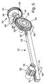
- Fig. 1 to 5 show a schematic representation of an exemplary embodiment of a door drive 10 according to the invention, in the illustration according to Fig. 1 for example, is provided as a top door closer for a revolving door.
- the door drive 10 includes a housing 12, a rotatably mounted in the housing 12 and coupled to a door leaf 14 or a frame 16 output shaft 18, a motor 20, in particular electric motor, for driving the output shaft 18 and a spring unit 22, during a respective opening movement of the Door leaf 14 is tensioned and relaxes during a respective closing movement of the door leaf 14 to provide a closing moment.
- the door drive 10 in the illustration according to Fig. 1 For example, provided as a top door closer for a revolving door.
- the housing 12 is mounted with the output shaft 18 on the door leaf 14 and the output shaft 18 connected to a lever 24 which is provided with a sliding block or the like, which is guided in a slide rail 26 which is fixed to the frame 16.
- the toothed rack 28 comprises a wave-shaped toothed section 34, which meshes with a non-circular toothing 32 of the output shaft 18.
- the motor 20 may in particular be designed as an electric motor.
- the door drive 10 may include a transformer and an electronic control device for controlling the motor 20.
- a corresponding control of the motor 20 for example, take place when a danger situation is signaled via a smoke detector.
- the rack 28 includes a gear portion 36 which meshes with a round pinion 38 of the front-cone gear 30.
- a toothed drive shaft 40 of the motor 20 meshes with a larger gear 42 which sits on a shaft 44 at one end of a bevel pinion 46 is arranged, which meshes with a bevel gear 48.
- the bevel gear 48 is seated on a further shaft 50, on which a pinion 52 is arranged, which meshes with a larger gear 54.
- the gear 54 is seated on a further shaft 56 on which the already mentioned, with the toothed portion 36 of the rack 28 meshing pinion 38 is arranged.
- the rack 28 is axially displaceably mounted in the housing 12.
- the toothed portion 36 of the rack 28 is designed in the present case, for example, linear.
- the spring unit 22 comprises a pushed onto the rack 28 compression spring which is disposed between a pushed onto the rack 28, supported on the housing 12 sleeve 58 and provided on the rack 28 radial stop 60.
- the radial stop 60 is formed for example by a pushed onto the rack 28 disc, which is supported on two diametrically opposite nose-like radial projections 62 of the rack 28.
- Axialnadellager 64 is provided between the formed by a disc radial stop 60 and the spring unit 22 is a pushed onto the rack 28 Axialnadellager 64 is provided. Between the radial stop 60 formed by the disc and the axial needle bearing 64, a spacer 66 is arranged, which is also pushed onto the rack 28. At the two nose-like radial projections 62 are thus on the rack 28 lined up by the disc formed radial stopper 60, the spacer 66, the Axialnadellager 64 and formed by a compression spring unit 22, while the spring unit formed by a compression spring at its other End of the also pushed onto the spring unit 22 sleeve 58 rests, over which the spring preload and thus the door closing torque in the currentless operation is adjustable. In this case, the sleeve 58 may in particular be adjustably mounted in the housing 12. The aforementioned parts are all threaded on the rack 28, i. interspersed by this.
- the shaft-shaped toothing section 34 of the rack 28 engaging with the output shaft 18 is provided on the same side of the rack 28 as the linear gear section 36 engaged with the bevel gear 30.
- the two gear sections 34, 36 of the rack 28 point in the present case in the same direction.
- the toothed rack 28 is supported in the area of its gear teeth sections 34, 36, which are in engagement with the output shaft 18 and with the bevel gear 30, in each case via a roller 68 mounted on the side of the toothed rack 28 remote from the respective toothed section 34, 36. In the direction of force everything is thus stored on roller bearings.
- the non-circular toothing 32 of the output shaft 18 and the meshing with this wave-shaped toothed portion 34 of the rack 28 may in particular be designed so that the torque transmitted from the spring unit 22 to the output shaft 18 torque decreases with increasing opening angle of the door leaf 14.
- the non-circular toothing 32 of the output shaft 18 and the meshing with this wave-shaped toothed portion 34 of the rack 28 in particular be designed so that the transmitted from the spring unit 22 to the output shaft 18 torque from an opening angle of the door leaf 14 in the range of 4 ° increasing opening angle of the door leaf 14 decreases.
- the radius at which the spring force is transmitted from the rack 28 to the output shaft 18 at relatively small opening angles of the door leaf 14 may be relatively large and smaller with increasing opening angles.
- the torque on the output shaft 18 at small opening angles of the door leaf 14 is large and decreases with the door opening 14 opening.
- the door drive 10 is characterized, inter alia, by a compact and inexpensive construction, a high efficiency at each opening angle of the door leaf 14 and a reduced risk of self-locking when normally closed by the spring force.
- a high closing torque can be generated, while at opening angles greater than 4 °, the door closing torque can decrease with increasing opening angle.
Description
- Die vorliegende Erfindung betrifft einen Türantrieb, insbesondere Drehtürantrieb, mit einem Gehäuse, einer drehbar im Gehäuse gelagerten und mit einem Türflügel oder einem Blendrahmen koppelbaren Abtriebsachse, einem Motor zum Antreiben der Abtriebsachse und einer Federeinheit, die während einer jeweiligen Öffnungsbewegung des Türflügels gespannt wird und sich während einer jeweiligen Schließbewegung des Türflügels entspannt, um ein Schließmoment zu liefern.
- Derartige Türantriebe dienen dazu, den Flügel einer motorisch geöffneten Tür mit Federkraft zu schließen. Dies ist insbesondere bei Rauch- und Feuerschutztüren von Bedeutung, die im Alarmfall, insbesondere nach Ansprechen eines Rauchmelders oder bei Stromausfall, schnell und zuverlässig geschlossen werden müssen. Mit dem Öffnen des Türflügels wird gleichzeitig die Federeinheit gespannt. Mit Hilfe der Federeinheit kann der Türantrieb den Türflügel somit auch bei einem Stromausfall schließen, was bei Brandschutztüren zwingend ist.
- Bei den bisher üblichen Drehtürantrieben der eingangs genannten Art werden zur Kraftübertragung zwischen Motor und Abtriebsachse häufig Schneckengetriebe eingesetzt. Solche Schneckengetriebe besitzen jedoch infolge der Gleitreibung an der Schnecke relativ niedrige Wirkungsgrade, die sich bei Mangelschmierung und tiefen Temperaturen noch verschlechtern können. Zudem besteht bei einem Stromausfall die Gefahr einer Selbsthemmung. Von Nachteil ist insbesondere auch, dass das Schließ- und Öffnungsmoment des Türflügels bei Öffnungswinkeln größer als 4° nicht in der gewünschten Weise abnimmt, was die manuelle Begehung der Tür erschwert.
- Es sind auch Drehtürantriebe mit Riemen- oder Nockenscheibengetrieben bekannt. Solche Riemen- und Nockenscheibengetriebe sind jedoch relativ aufwendig.
- Drehtürantriebe der gattungsgemäßen Art sind aus der
WO 01/98615 A1 US 4 333 270 A ,EP 0 733 763 A1 undUS 2007/256362 A1 bekannt. - Der Erfindung liegt die Aufgabe zugrunde, einen Türantrieb, insbesondere Drehtürantrieb, der eingangs genannten Art anzugeben, bei dem die zuvor erwähnten Nachteile beseitigt sind. Dabei sollen insbesondere der Wirkungsgrad erhöht und die Gefahr einer Selbsthemmung reduziert werden. Zudem soll der Türantrieb einen relativ einfachen, kompakten Aufbau besitzen und mit möglichst wenig Aufwand eine hinreichende Abnahme des Schließ- und Öffnungsmoments zu größeren Öffnungswinkeln hin ermöglichen.
- Die Aufgabe wird erfindungsgemäß durch einen Türantrieb mit den Merkmalen des Anspruchs 1 gelöst. Bevorzugte Ausführungsformen des erfindungsgemäßen Türantriebs ergeben sich aus den Unteransprüchen, der vorliegenden Beschreibung sowie der Zeichnung.
- Der erfindungsgemäße Türantrieb, insbesondere Drehtürantrieb, umfasst ein Gehäuse, eine drehbar im Gehäuse gelagerte und mit einem Türflügel oder einem Blendrahmen koppelbare Abtriebsachse, einen Motor zum Antreiben der Abtriebsachse und eine Federeinheit, die während einer jeweiligen Öffnungsbewegung des Türflügels gespannt wird und sich während einer jeweiligen Schließbewegung des Türflügels entspannt, um ein Schließmoment zu liefern. Dabei ist die Abtriebsachse über eine Zahnstange durch den Motor antreibbar, die einerseits über ein Getriebe, insbesondere ein Stirn-Kegel-Getriebe, vom Motor beaufschlagbar ist und andererseits mit einer Verzahnung der Abtriebsachse kämmt.
- Aufgrund dieser Ausbildung ergibt sich nicht nur ein höherer Wirkungsgrad, aufgrund des mehrstufigen Getriebes ohne Gleitreibung ist auch die Gefahr einer Selbsthemmung auf ein Minimum reduziert. Auch bei einem Stromausfall ist somit gewährleistet, dass der Türflügel über die Federeinheit zuverlässig geschlossen wird. Der Türantrieb besitzt einen insgesamt einfacheren und kompakteren Aufbau. Zudem kann nunmehr insbesondere durch eine entsprechende Auslegung der Verzahnung der Abtriebsachse und des mit dieser kämmenden Verzahnungsabschnitts der Zahnstange auf einfache Weise ein zu größeren Öffnungswinkeln hin in der gewünschten Weise abnehmendes Schließ- und Öffnungsmoment realisiert werden.
- Gemäß einer bevorzugten praktischen Ausführungsform des erfindungsgemäßen Türantriebs umfasst die Zahnstange einen wellenförmigen Verzahnungsabschnitt, der mit einer Unrund-Verzahnung der Abtriebsachse kämmt.
- Mit einer solchen Gestaltung der zusammenwirkenden Verzahnungen der Abtriebsachse und der Zahnstange kann das sich ergebende Schließ- und Öffnungsmoment in der gewünschten Weise beeinflusst werden. So kann ein jeweils gewünschter Verlauf des Schließ- und Öffnungsmoments insbesondere durch eine entsprechende Wahl der Wellenform des Verzahnungsabschnitts der Zahnstange und eine entsprechende Wahl der Form der Unrund-Verzahnung der Abtriebsachse vorgegeben werden.
- Das Stirn-Kegel-Getriebe ist bevorzugt als mehrstufiges Stirn-Kegel-Getriebe ausgeführt, um die gewünschte Übersetzung zu realisieren.
- Die Zahnstange umfasst zweckmäßigerweise einen Verzahnungsabschnitt, der mit einem runden Ritzel des Stirn-Kegel-Getriebes kämmt.
- Die Zahnstange ist bevorzugt axial verschiebbar im Gehäuse gelagert.
- Von Vorteil ist insbesondere auch, wenn die Federeinheit eine auf die Zahnstange aufgeschobene Druckfeder umfasst, womit sich ein besonders kompakter Aufbau ergibt.
- Gemäß einer bevorzugten praktischen Ausführungsform des erfindungsgemäßen Türantriebs ist die Federeinheit zwischen einer auf die Zahnstange aufgeschobenen, am Gehäuse abgestützten Hülse und einem an der Zahnstange vorgesehenen radialen Anschlag angeordnet.
- Über die Hülse kann die Vorspannung der Federeinheit und damit insbesondere das Schließmoment des Türflügels im stromlosen Betrieb eingestellt werden. Dazu kann die Hülse insbesondere verstellbar im Gehäuse gelagert sein. Indem auch die Hülse auf die Zahnstange aufgeschoben ist, wird ein möglichst kompakter Aufbau des Türantriebs gewährleistet.
- Der radiale Anschlag kann insbesondere eine auf die Zahnstange aufgeschobene, an wenigstens einem radialen Vorsprung der Zahnstange abgestützte Scheibe umfassen. Dabei kann die Zahnstange beispielsweise mit zwei einander diametral entgegengesetzten nasenartigen radialen Vorsprüngen versehen sein, um die Scheibe abzustützen. Zwischen dem radialen Anschlag und der Federeinheit ist bevorzugt ein auf die Zahnstange aufgeschobenes Axiallager, insbesondere Axialnadellager, vorgesehen. Dabei ergibt sich mit einem Axialnadellager eine besonders niedrige Bauform.
- Von Vorteil ist insbesondere auch, wenn der mit der Abtriebsachse in Eingriff stehende Verzahnungsabschnitt der Zahnstange auf derselben Seite der Zahnstange vorgesehen ist, wie deren mit dem Stirn-Kegel-Getriebe in Eingriff stehender Verzahnungsabschnitt. Die Verzahnungsabschnitte der Zahnstange weisen somit in dieselbe Richtung.
- Um eine möglichst reibungsarme Lagerung der Zahnstange im Gehäuse zu gewährleisten, ist erfindungsgemäß die Zahnstange im Bereich deren mit der Abtriebsachse und mit dem Stirn-Kegel-Getriebe in Eingriff stehenden Verzahnungsabschnitten jeweils über wenigstens eine auf der vom jeweiligen Verzahnungsabschnitt abgewandten Seite der Zahnstange angeordnete insbesondere wälzgelagerte Rolle abgestützt.
- Von Vorteil ist zudem, wenn insbesondere die Unrund-Verzahnung der Abtriebsachse und der mit dieser kämmende wellenförmige Verzahnungsabschnitt der Zahnstange so gestaltet sind, dass das von der Federeinheit auf die Abtriebsachse übertragene Drehmoment mit zunehmendem Öffnungswinkel des Türflügels abnimmt.
- Dabei sind die Unrund-Verzahnung der Abtriebsachse und der mit dieser kämmende wellenförmige Verzahnungsabschnitt der Zahnstange bevorzugt so gestaltet, dass das von der Federeinheit auf die Abtriebsachse übertragene Drehmoment ab einem Öffnungswinkel des Türflügels im Bereich von 4° mit zunehmendem Öffnungswinkel des Türflügels abnimmt.
- Die Erfindung wird im Folgenden anhand eines Ausführungsbeispiels unter Bezugnahme auf die Zeichnung näher erläutert; in dieser zeigen:
- Fig. 1
- eine schematische Darstellung einer beispielhaften Ausführungsform eines beispielsweise als Obentürschließer vorgesehenen erfindungsgemäßen Türantriebs,
- Fig. 2
- eine schematische Schnittdarstellung des Türantriebs gemäß
Fig. 1 , - Fig. 3
- eine schematische Draufsicht des Stirn-Kegel-Getriebes, der Zahnstange und der Abtriebsachse des Türantriebs gemäß
Fig. 1 , - Fig. 4
- eine schematische Seitenansicht des Stirn-Kegel-Getriebes, der Zahnstange und der Abtriebsachse des Türantriebs gemäß
Fig. 1 , und - Fig. 5
- eine schematische perspektivische Ansicht des Stirn-Kegel-Getriebes, der Zahnstange und der Abtriebsachse des Türantriebs gemäß
Fig. 1 . - Die
Fig. 1 bis 5 zeigen in schematischer Darstellung eine beispielhafte Ausführungsform eines erfindungsgemäßen Türantriebs 10, der in der Darstellung gemäßFig. 1 beispielsweise als Obentürschließer für eine Drehtür vorgesehen ist. - Der Türantrieb 10 umfasst ein Gehäuse 12, eine drehbar im Gehäuse 12 gelagerte und mit einem Türflügel 14 oder einem Blendrahmen 16 koppelbaren Abtriebsachse 18, einem Motor 20, insbesondere Elektromotor, zum Antreiben der Abtriebsachse 18 und eine Federeinheit 22, die während einer jeweiligen Öffnungsbewegung des Türflügels 14 gespannt wird und sich während einer jeweiligen Schließbewegung des Türflügels 14 entspannt, um ein Schließmoment zu liefern.
- Dabei ist der Türantrieb 10 in der Darstellung gemäß
Fig. 1 beispielsweise als Obentürschließer für eine Drehtür vorgesehen. Im vorliegenden Fall ist das Gehäuse 12 mit der Abtriebsachse 18 am Türflügel 14 angebracht und die Abtriebsachse 18 mit einem Hebel 24 verbunden, der mit einem Gleitstein oder dergleichen versehen ist, der in einer Gleitschiene 26 geführt ist, die am Blendrahmen 16 fixiert ist. - Wie den
Fig. 2 bis 5 zu entnehmen ist, ist die Abtriebsachse 18 über eine Zahnstange 28 durch den Motor 20 antreibbar, die einerseits über ein Stirn-Kegel-Getriebe 30 vom Motor 20 beaufschlagbar ist und andererseits mit einer Verzahnung 32 der Abtriebsachse 18 kämmt. - Dabei umfasst die Zahnstange 28 einen wellenförmigen Verzahnungsabschnitt 34, der mit einer Unrund-Verzahnung 32 der Abtriebsachse 18 kämmt.
- Der Motor 20 kann insbesondere als Elektromotor ausgeführt sein. Zudem kann der Türantrieb 10 einen Transformator sowie eine elektronische Steuereinrichtung zur Ansteuerung des Motors 20 umfassen. Hierbei kann eine entsprechende Ansteuerung des Motors 20 beispielsweise dann erfolgen, wenn über einen Rauchmelder eine Gefahrensituation signalisiert wird.
- Die Zahnstange 28 umfasst einen Verzahnungsabschnitt 36, der mit einem runden Ritzel 38 des Stirn-Kegel-Getriebes 30 kämmt.
- Wie am besten anhand der
Fig. 3 bis 5 zu erkennen ist, kämmt eine mit einer Verzahnung versehene Antriebswelle 40 des Motors 20 mit einem größeren Zahnrad 42, das auf einer Welle 44 sitzt, an deren einem Ende ein Kegelritzel 46 angeordnet ist, das mit einem Kegelrad 48 kämmt. Das Kegelrad 48 sitzt auf einer weiteren Welle 50, auf dem ein Ritzel 52 angeordnet ist, das mit einem größeren Zahnrad 54 kämmt. Das Zahnrad 54 sitzt auf einer weiteren Welle 56, auf der auch das bereits erwähnte, mit dem Verzahnungsabschnitt 36 der Zahnstange 28 kämmende Ritzel 38 angeordnet ist. - Die Zahnstange 28 ist axial verschiebbar im Gehäuse 12 gelagert.
- Der Verzahnungsabschnitt 36 der Zahnstange 28 ist im vorliegenden Fall beispielsweise linear ausgeführt.
- Wie anhand der
Fig. 2 zu erkennen ist, umfasst die Federeinheit 22 eine auf die Zahnstange 28 aufgeschobene Druckfeder, die zwischen einer auf die Zahnstange 28 aufgeschobenen, am Gehäuse 12 abgestützten Hülse 58 und einem an der Zahnstange 28 vorgesehenen radialen Anschlag 60 angeordnet ist. - Im vorliegenden Fall ist der radiale Anschlag 60 beispielsweise durch eine auf die Zahnstange 28 aufgeschobene Scheibe gebildet, die an zwei einander diametral gegenüberliegenden nasenartigen radialen Vorsprüngen 62 der Zahnstange 28 abgestützt ist.
- Zwischen dem durch eine Scheibe gebildeten radialen Anschlag 60 und der Federeinheit 22 ist ein auf die Zahnstange 28 aufgeschobenes Axialnadellager 64 vorgesehen. Zwischen dem durch die Scheibe gebildeten radialen Anschlag 60 und dem Axialnadellager 64 ist ein Distanzstück 66 angeordnet, das ebenfalls auf die Zahnstange 28 aufgeschoben ist. An den beiden nasenartigen radialen Vorsprüngen 62 liegen somit auf die Zahnstange 28 aufgereiht der durch die Scheibe gebildete radiale Anschlag 60, das Distanzstück 66, das Axialnadellager 64 und die durch eine Druckfeder gebildete Federeinheit 22 an, während die durch eine Druckfeder gebildete Federeinheit an ihrem anderen Ende an der ebenfalls auf die Federeinheit 22 aufgeschobenen Hülse 58 anliegt, über die die Federvorspannung und damit das Türschließmoment im stromlosen Betrieb einstellbar ist. Dabei kann die Hülse 58 insbesondere verstellbar im Gehäuse 12 gelagert sein. Die zuvor genannten Teile sind alle auf der Zahnstange 28 aufgefädelt, d.h. von dieser durchsetzt.
- Der mit der Abtriebsachse 18 in Eingriff stehende wellenförmige Verzahnungsabschnitt 34 der Zahnstange 28 ist auf derselben Seite der Zahnstange 28 vorgesehen, wie deren mit dem Stirn-Kegel-Getriebe 30 in Eingriff stehender linearer Verzahnungsabschnitt 36. Die beiden Verzahnungsabschnitte 34, 36 der Zahnstange 28 weisen im vorliegenden Fall also in dieselbe Richtung.
- Die Zahnstange 28 ist im Bereich deren mit der Abtriebsachse 18 und mit dem Stirn-Kegel-Getriebe 30 in Eingriff stehenden Verzahnungsabschnitten 34, 36 jeweils über eine auf der vom jeweiligen Verzahnungsabschnitt 34, 36 abgewandten Seite der Zahnstange 28 angeordnete insbesondere wälzgelagerte Rolle 68 abgestützt. In Kraftrichtung ist somit alles wälzgelagert.
- Die Unrund-Verzahnung 32 der Abtriebsachse 18 und der mit dieser kämmende wellenförmige Verzahnungsabschnitt 34 der Zahnstange 28 können insbesondere so gestaltet sein, dass das von der Federeinheit 22 auf die Abtriebsachse 18 übertragene Drehmoment mit zunehmendem Öffnungswinkel des Türflügels 14 abnimmt. Dabei können die Unrund-Verzahnung 32 der Abtriebsachse 18 und der mit dieser kämmende wellenförmige Verzahnungsabschnitt 34 der Zahnstange 28 insbesondere so gestaltet sein, dass das von der Federeinheit 22 auf die Abtriebsachse 18 übertragene Drehmoment ab einem Öffnungswinkel des Türflügels 14 im Bereich von 4° mit zunehmendem Öffnungswinkel des Türflügels 14 abnimmt. Dabei kann der Radius, an dem die Federkraft von der Zahnstange 28 auf die Abtriebsachse 18 übertragen wird, bei kleinen Öffnungswinkeln des Türflügels 14 relativ groß sein und bei zunehmenden Öffnungswinkeln kleiner werden. Damit ist das Moment an der Abtriebsachse 18 bei kleinen Öffnungswinkeln des Türflügels 14 groß und nimmt mit sich öffnendem Türflügel 14 ab.
- Der Türantrieb 10 zeichnet sich unter anderem durch einen kompakten und kostengünstigen Aufbau, einen hohen Wirkungsgrad bei jedem Öffnungswinkel des Türflügels 14 sowie eine reduzierte Selbsthemmungsgefahr beim stromlosen Schließen durch die Federkraft aus. Beispielsweise in einem Öffnungswinkelbereich zwischen 0° und 4° kann ein hohes Schließmoment erzeugt werden, während bei Öffnungswinkeln größer als 4° das Türschließmoment mit zunehmendem Öffnungswinkel abnehmen kann.
-
- 10
- Türantrieb
- 12
- Gehäuse
- 14
- Türflügel
- 16
- Blendrahmen
- 18
- Abtriebsachse
- 20
- Motor
- 22
- Federeinheit
- 24
- Hebel
- 26
- Gleitschiene
- 28
- Zahnstange
- 30
- Stirn-Kegel-Getriebe
- 32
- Unrund-Verzahnung der Abtriebsachse
- 34
- wellenförmiger Verzahnungsabschnitt
- 36
- linearer Verzahnungsabschnitt
- 38
- rundes Ritzel
- 40
- Antriebswelle
- 42
- Zahnrad
- 44
- Welle
- 46
- Kegelritzel
- 48
- Kegelrad
- 50
- Welle
- 52
- Ritzel
- 54
- Zahnrad
- 56
- Welle
- 58
- Hülse
- 60
- radialer Anschlag
- 62
- radialer Vorsprung
- 64
- Axialnadellager
- 66
- Distanzstück
- 68
- Rolle
Claims (13)
- Türantrieb (10), insbesondere Drehtürantrieb, mit einem Gehäuse (12), einer drehbar im Gehäuse (12) gelagerten und mit einem Türflügel (14) oder einem Blendrahmen (16) koppelbaren Abtriebsachse (18), einem Motor (20) zum Antreiben der Abtriebsachse (18) und einer Federeinheit (22), die während einer jeweiligen Öffnungsbewegung des Türflügels (14) gespannt wird und sich während einer jeweiligen Schließbewegung des Türflügels (14) entspannt, um ein Schließmoment zu liefern, wobei die Abtriebsachse (18) über eine Zahnstange (28) durch den Motor (20) antreibbar ist, die einerseits über ein mehrstufiges Getriebe vom Motor (20) beaufschlagbar ist und andererseits mit einer Verzahnung (32) der Abtriebsachse (18) kämmt,
dadurch gekennzeichnet, dass
die Zahnstange (28) im Bereich deren mit der Abtriebsachse (18) und mit dem als Stirn-Kegel-Getriebe ausgeführten Getriebe (30) in Eingriff stehenden Verzahnungsabschnitten (34, 36) jeweils über wenigstens eine auf der vom jeweiligen Verzahnungsabschnitt (34, 36) abgewandten Seite der Zahnstange angeordnete, insbesondere wälzgelagerte, Rolle (68) abgestützt ist. - Türantrieb nach Anspruch 1,
dadurch gekennzeichnet, dass das mehrstufiges Getriebe als Stirn-Kegel-Getriebe (30) ausgebildet ist. - Türantrieb nach Anspruch 1 oder 2,
dadurch gekennzeichnet, dass die Zahnstange (28) einen wellenförmigen Verzahnungsabschnitt (34) umfasst, der mit einer Unrund-Verzahnung (32) der Abtriebsachse (18) kämmt. - Türantrieb nach einem der vorstehenden Ansprüche,
dadurch gekennzeichnet, dass das Stirn-Kegel-Getriebe (30) als mehrstufiges Stirn-Kegel-Getriebe ausgeführt ist. - Türantrieb nach zumindest einem der vorstehenden Ansprüche,
dadurch gekennzeichnet, dass die Zahnstange (28) einen gera- den Verzahnungsabschnitt (36) umfasst, der mit einem runden Ritzel (38) des Stirn- Kegel-Getriebes (30) kämmt. - Türantrieb nach zumindest einem der vorstehenden Ansprüche,
dadurch gekennzeichnet, dass die Zahnstange (28) axial ver- schiebbar im Gehäuse (12) gelagert ist. - Türantrieb nach zumindest einem der vorstehenden Ansprüche,
dadurch gekennzeichnet, dass die Federeinheit (22) eine auf die Zahnstange (28) aufgeschobene Druckfeder umfasst. - Türantrieb nach zumindest einem der vorstehenden Ansprüche,
dadurch gekennzeichnet, dass die Federeinheit (22) zwischen einer auf die Zahnstange (28) aufgeschobenen, am Gehäuse (12) abgestützten Hülse (58) und einem an der Zahnstange (28) vorgesehenen radialen Anschlag (60) angeordnet ist. - Türantrieb nach Anspruch 8,
dadurch gekennzeichnet, dass der radiale Anschlag (60) eine auf die Zahnstange (28) aufgeschobene, an wenigstens einem radialen Vorsprung (62) der Zahnstange (28) abgestützte Scheibe umfasst. - Türantrieb nach Anspruch 8 oder 9,
dadurch gekennzeichnet, dass zwischen dem radialen Anschlag (60) und der Federeinheit (22) ein auf die Zahnstange (28) aufgeschobenes Axiallager, insbesondere Axialnadellager (64), vorgesehen ist. - Türantrieb nach zumindest einem der vorstehenden Ansprüche,
dadurch gekennzeichnet , dass der mit der Abtriebsachse (18) in Eingriff stehende Verzahnungsabschnitt (34) der Zahnstange (28) auf derselben Seite der Zahnstange (28) vorgesehen ist wie deren mit dem Stirn-Kegel-Getriebe (30) in Eingriff stehender Verzahnungsabschnitt (36). - Türantrieb nach zumindest einem der vorstehenden Ansprüche,
dadurch gekennzeichnet, dass die Unrund-Verzahnung (32) der Abtriebsachse (18) und der mit dieser kämmende wellenförmige Verzahnungsabschnitt (34) der Zahnstange (28) so gestaltet sind, dass das von der Federeinheit (22) auf die Abtriebsachse (18) übertragende Drehmoment mit zunehmendem Öffnungswinkel des Türflügels (14) abnimmt. - Türantrieb nach Anspruch 12,
dadurch gekennzeichnet, dass die Unrund-Verzahnung (32) der Abtriebsachse (18) und der mit dieser kämmende wellenförmige Verzahnungsabschnitt (34) der Zahnstange (28) so gestaltet sind, dass das von der Federeinheit (22) auf die Abtriebsachse (18) übertragende Drehmoment ab einem Öffnungswinkel des Türflügels (14) im Bereich von 4° mit zunehmendem Öffnungswinkel des Türflügels (14) abnimmt.
Applications Claiming Priority (2)
| Application Number | Priority Date | Filing Date | Title |
|---|---|---|---|
| DE102014207217.4A DE102014207217B3 (de) | 2014-04-15 | 2014-04-15 | Drehtürantrieb |
| DE102015202830.5A DE102015202830B3 (de) | 2015-02-17 | 2015-02-17 | Türantrieb |
Publications (2)
| Publication Number | Publication Date |
|---|---|
| EP2933413A1 EP2933413A1 (de) | 2015-10-21 |
| EP2933413B1 true EP2933413B1 (de) | 2016-11-09 |
Family
ID=52811063
Family Applications (1)
| Application Number | Title | Priority Date | Filing Date |
|---|---|---|---|
| EP15162782.5A Active EP2933413B1 (de) | 2014-04-15 | 2015-04-08 | Türantrieb |
Country Status (3)
| Country | Link |
|---|---|
| EP (1) | EP2933413B1 (de) |
| CN (1) | CN105041100B (de) |
| ES (1) | ES2614255T3 (de) |
Families Citing this family (2)
| Publication number | Priority date | Publication date | Assignee | Title |
|---|---|---|---|---|
| DE102016200632A1 (de) * | 2016-01-19 | 2017-07-20 | Geze Gmbh | Elektromotorischer Antrieb |
| KR20210007645A (ko) * | 2019-07-12 | 2021-01-20 | 엘지전자 주식회사 | 냉장고 |
Family Cites Families (6)
| Publication number | Priority date | Publication date | Assignee | Title |
|---|---|---|---|---|
| US4333270A (en) * | 1980-02-22 | 1982-06-08 | Besam-Eads, Inc. | Automatic door operator |
| EP0733763B1 (de) * | 1995-03-21 | 2000-08-16 | GEZE GmbH | Türschliesser |
| DE10029161C1 (de) * | 2000-06-19 | 2002-01-24 | Dorma Gmbh & Co Kg | Anordnung für das Öffnen und Schließen einer Tür oder eines Tores |
| DE10148293A1 (de) * | 2001-09-29 | 2003-04-24 | Landert Motoren Ag | Flügeltürantrieb mit Federschliessung |
| CN2752399Y (zh) * | 2004-11-28 | 2006-01-18 | 冷亮 | 一种用于开关门的自动控制器 |
| US20070256362A1 (en) * | 2006-03-04 | 2007-11-08 | Curtis David Hansen | Assembly and method for automated operation of a restroom door |
-
2015
- 2015-04-08 EP EP15162782.5A patent/EP2933413B1/de active Active
- 2015-04-08 ES ES15162782.5T patent/ES2614255T3/es active Active
- 2015-04-15 CN CN201510368952.3A patent/CN105041100B/zh active Active
Also Published As
| Publication number | Publication date |
|---|---|
| EP2933413A1 (de) | 2015-10-21 |
| CN105041100B (zh) | 2017-12-08 |
| ES2614255T3 (es) | 2017-05-30 |
| CN105041100A (zh) | 2015-11-11 |
Similar Documents
| Publication | Publication Date | Title |
|---|---|---|
| EP2841667B1 (de) | Drehflügelantrieb | |
| DE2913887C2 (de) | ||
| EP2933414A1 (de) | Türantrieb | |
| DE102013100782B4 (de) | Stopperzylinder | |
| EP2933415B1 (de) | Türantrieb | |
| DE102007043391A1 (de) | Aktuator mit verlagerbarem Ausleger | |
| EP2345569B1 (de) | Schraubradgetriebe für eine Lenkung eines Kraftfahrzeugs | |
| WO2018224248A1 (de) | Loslager, lenkgetriebe und lenksystem | |
| DE3522706C2 (de) | Vorrichtung für Linearantrieb | |
| EP1298274A1 (de) | Flügeltürantrieb mit Federschliessung | |
| EP2933413B1 (de) | Türantrieb | |
| EP1767389A2 (de) | Schwenkschiebetür für Fahrzeuge, insbesondere Fahrgasttür für Fahrzeuge des öffentlichen Personnenverkehrs | |
| DE2718928A1 (de) | Verstellbarer, insbesondere in einem fahrzeug, vorzugsweise kraftwagen anzuordnender sitz | |
| DE202007002787U1 (de) | Fangvorrichtung zum Stillsetzen einer Umlenk- oder Wickelwelle | |
| DE102015211503B4 (de) | Türantrieb | |
| DE102015202830B3 (de) | Türantrieb | |
| EP2933412A1 (de) | Drehtürantrieb | |
| EP1375812A2 (de) | Antriebssystem für eine Lamellenanordnung | |
| DE19604501C2 (de) | Getriebe | |
| DE102015202832B3 (de) | Türantrieb | |
| EP3325751A1 (de) | Antrieb für einen drehbaren flügel | |
| EP2933410A1 (de) | Türantrieb | |
| DE102015202852B3 (de) | Türantrieb | |
| DE102015202835B3 (de) | Türantrieb | |
| EP2960415B1 (de) | Türantrieb |
Legal Events
| Date | Code | Title | Description |
|---|---|---|---|
| PUAI | Public reference made under article 153(3) epc to a published international application that has entered the european phase |
Free format text: ORIGINAL CODE: 0009012 |
|
| AK | Designated contracting states |
Kind code of ref document: A1 Designated state(s): AL AT BE BG CH CY CZ DE DK EE ES FI FR GB GR HR HU IE IS IT LI LT LU LV MC MK MT NL NO PL PT RO RS SE SI SK SM TR |
|
| AX | Request for extension of the european patent |
Extension state: BA ME |
|
| 17P | Request for examination filed |
Effective date: 20160120 |
|
| RBV | Designated contracting states (corrected) |
Designated state(s): AL AT BE BG CH CY CZ DE DK EE ES FI FR GB GR HR HU IE IS IT LI LT LU LV MC MK MT NL NO PL PT RO RS SE SI SK SM TR |
|
| GRAP | Despatch of communication of intention to grant a patent |
Free format text: ORIGINAL CODE: EPIDOSNIGR1 |
|
| INTG | Intention to grant announced |
Effective date: 20160621 |
|
| GRAS | Grant fee paid |
Free format text: ORIGINAL CODE: EPIDOSNIGR3 |
|
| GRAA | (expected) grant |
Free format text: ORIGINAL CODE: 0009210 |
|
| AK | Designated contracting states |
Kind code of ref document: B1 Designated state(s): AL AT BE BG CH CY CZ DE DK EE ES FI FR GB GR HR HU IE IS IT LI LT LU LV MC MK MT NL NO PL PT RO RS SE SI SK SM TR |
|
| REG | Reference to a national code |
Ref country code: GB Ref legal event code: FG4D Free format text: NOT ENGLISH |
|
| REG | Reference to a national code |
Ref country code: AT Ref legal event code: REF Ref document number: 844089 Country of ref document: AT Kind code of ref document: T Effective date: 20161115 Ref country code: CH Ref legal event code: EP |
|
| REG | Reference to a national code |
Ref country code: IE Ref legal event code: FG4D Free format text: LANGUAGE OF EP DOCUMENT: GERMAN |
|
| REG | Reference to a national code |
Ref country code: DE Ref legal event code: R096 Ref document number: 502015000284 Country of ref document: DE |
|
| REG | Reference to a national code |
Ref country code: SE Ref legal event code: TRGR |
|
| PG25 | Lapsed in a contracting state [announced via postgrant information from national office to epo] |
Ref country code: LV Free format text: LAPSE BECAUSE OF FAILURE TO SUBMIT A TRANSLATION OF THE DESCRIPTION OR TO PAY THE FEE WITHIN THE PRESCRIBED TIME-LIMIT Effective date: 20161109 |
|
| REG | Reference to a national code |
Ref country code: LT Ref legal event code: MG4D |
|
| REG | Reference to a national code |
Ref country code: NL Ref legal event code: MP Effective date: 20161109 |
|
| REG | Reference to a national code |
Ref country code: FR Ref legal event code: PLFP Year of fee payment: 3 |
|
| PG25 | Lapsed in a contracting state [announced via postgrant information from national office to epo] |
Ref country code: GR Free format text: LAPSE BECAUSE OF FAILURE TO SUBMIT A TRANSLATION OF THE DESCRIPTION OR TO PAY THE FEE WITHIN THE PRESCRIBED TIME-LIMIT Effective date: 20170210 Ref country code: NO Free format text: LAPSE BECAUSE OF FAILURE TO SUBMIT A TRANSLATION OF THE DESCRIPTION OR TO PAY THE FEE WITHIN THE PRESCRIBED TIME-LIMIT Effective date: 20170209 Ref country code: NL Free format text: LAPSE BECAUSE OF FAILURE TO SUBMIT A TRANSLATION OF THE DESCRIPTION OR TO PAY THE FEE WITHIN THE PRESCRIBED TIME-LIMIT Effective date: 20161109 Ref country code: LT Free format text: LAPSE BECAUSE OF FAILURE TO SUBMIT A TRANSLATION OF THE DESCRIPTION OR TO PAY THE FEE WITHIN THE PRESCRIBED TIME-LIMIT Effective date: 20161109 |
|
| REG | Reference to a national code |
Ref country code: ES Ref legal event code: FG2A Ref document number: 2614255 Country of ref document: ES Kind code of ref document: T3 Effective date: 20170530 |
|
| PG25 | Lapsed in a contracting state [announced via postgrant information from national office to epo] |
Ref country code: PT Free format text: LAPSE BECAUSE OF FAILURE TO SUBMIT A TRANSLATION OF THE DESCRIPTION OR TO PAY THE FEE WITHIN THE PRESCRIBED TIME-LIMIT Effective date: 20170309 Ref country code: HR Free format text: LAPSE BECAUSE OF FAILURE TO SUBMIT A TRANSLATION OF THE DESCRIPTION OR TO PAY THE FEE WITHIN THE PRESCRIBED TIME-LIMIT Effective date: 20161109 Ref country code: PL Free format text: LAPSE BECAUSE OF FAILURE TO SUBMIT A TRANSLATION OF THE DESCRIPTION OR TO PAY THE FEE WITHIN THE PRESCRIBED TIME-LIMIT Effective date: 20161109 Ref country code: RS Free format text: LAPSE BECAUSE OF FAILURE TO SUBMIT A TRANSLATION OF THE DESCRIPTION OR TO PAY THE FEE WITHIN THE PRESCRIBED TIME-LIMIT Effective date: 20161109 Ref country code: IS Free format text: LAPSE BECAUSE OF FAILURE TO SUBMIT A TRANSLATION OF THE DESCRIPTION OR TO PAY THE FEE WITHIN THE PRESCRIBED TIME-LIMIT Effective date: 20170309 Ref country code: FI Free format text: LAPSE BECAUSE OF FAILURE TO SUBMIT A TRANSLATION OF THE DESCRIPTION OR TO PAY THE FEE WITHIN THE PRESCRIBED TIME-LIMIT Effective date: 20161109 |
|
| PG25 | Lapsed in a contracting state [announced via postgrant information from national office to epo] |
Ref country code: SK Free format text: LAPSE BECAUSE OF FAILURE TO SUBMIT A TRANSLATION OF THE DESCRIPTION OR TO PAY THE FEE WITHIN THE PRESCRIBED TIME-LIMIT Effective date: 20161109 Ref country code: EE Free format text: LAPSE BECAUSE OF FAILURE TO SUBMIT A TRANSLATION OF THE DESCRIPTION OR TO PAY THE FEE WITHIN THE PRESCRIBED TIME-LIMIT Effective date: 20161109 Ref country code: DK Free format text: LAPSE BECAUSE OF FAILURE TO SUBMIT A TRANSLATION OF THE DESCRIPTION OR TO PAY THE FEE WITHIN THE PRESCRIBED TIME-LIMIT Effective date: 20161109 Ref country code: RO Free format text: LAPSE BECAUSE OF FAILURE TO SUBMIT A TRANSLATION OF THE DESCRIPTION OR TO PAY THE FEE WITHIN THE PRESCRIBED TIME-LIMIT Effective date: 20161109 Ref country code: CZ Free format text: LAPSE BECAUSE OF FAILURE TO SUBMIT A TRANSLATION OF THE DESCRIPTION OR TO PAY THE FEE WITHIN THE PRESCRIBED TIME-LIMIT Effective date: 20161109 |
|
| REG | Reference to a national code |
Ref country code: DE Ref legal event code: R097 Ref document number: 502015000284 Country of ref document: DE |
|
| PG25 | Lapsed in a contracting state [announced via postgrant information from national office to epo] |
Ref country code: SM Free format text: LAPSE BECAUSE OF FAILURE TO SUBMIT A TRANSLATION OF THE DESCRIPTION OR TO PAY THE FEE WITHIN THE PRESCRIBED TIME-LIMIT Effective date: 20161109 Ref country code: BG Free format text: LAPSE BECAUSE OF FAILURE TO SUBMIT A TRANSLATION OF THE DESCRIPTION OR TO PAY THE FEE WITHIN THE PRESCRIBED TIME-LIMIT Effective date: 20170209 |
|
| PLBE | No opposition filed within time limit |
Free format text: ORIGINAL CODE: 0009261 |
|
| STAA | Information on the status of an ep patent application or granted ep patent |
Free format text: STATUS: NO OPPOSITION FILED WITHIN TIME LIMIT |
|
| 26N | No opposition filed |
Effective date: 20170810 |
|
| PG25 | Lapsed in a contracting state [announced via postgrant information from national office to epo] |
Ref country code: SI Free format text: LAPSE BECAUSE OF FAILURE TO SUBMIT A TRANSLATION OF THE DESCRIPTION OR TO PAY THE FEE WITHIN THE PRESCRIBED TIME-LIMIT Effective date: 20161109 |
|
| REG | Reference to a national code |
Ref country code: IE Ref legal event code: MM4A |
|
| PG25 | Lapsed in a contracting state [announced via postgrant information from national office to epo] |
Ref country code: MC Free format text: LAPSE BECAUSE OF FAILURE TO SUBMIT A TRANSLATION OF THE DESCRIPTION OR TO PAY THE FEE WITHIN THE PRESCRIBED TIME-LIMIT Effective date: 20161109 |
|
| PG25 | Lapsed in a contracting state [announced via postgrant information from national office to epo] |
Ref country code: LU Free format text: LAPSE BECAUSE OF NON-PAYMENT OF DUE FEES Effective date: 20170408 |
|
| REG | Reference to a national code |
Ref country code: BE Ref legal event code: MM Effective date: 20170430 |
|
| REG | Reference to a national code |
Ref country code: FR Ref legal event code: PLFP Year of fee payment: 4 |
|
| PG25 | Lapsed in a contracting state [announced via postgrant information from national office to epo] |
Ref country code: IE Free format text: LAPSE BECAUSE OF NON-PAYMENT OF DUE FEES Effective date: 20170408 |
|
| PG25 | Lapsed in a contracting state [announced via postgrant information from national office to epo] |
Ref country code: BE Free format text: LAPSE BECAUSE OF NON-PAYMENT OF DUE FEES Effective date: 20170430 |
|
| PG25 | Lapsed in a contracting state [announced via postgrant information from national office to epo] |
Ref country code: MT Free format text: LAPSE BECAUSE OF FAILURE TO SUBMIT A TRANSLATION OF THE DESCRIPTION OR TO PAY THE FEE WITHIN THE PRESCRIBED TIME-LIMIT Effective date: 20161109 |
|
| PG25 | Lapsed in a contracting state [announced via postgrant information from national office to epo] |
Ref country code: HU Free format text: LAPSE BECAUSE OF FAILURE TO SUBMIT A TRANSLATION OF THE DESCRIPTION OR TO PAY THE FEE WITHIN THE PRESCRIBED TIME-LIMIT; INVALID AB INITIO Effective date: 20150408 |
|
| PG25 | Lapsed in a contracting state [announced via postgrant information from national office to epo] |
Ref country code: CY Free format text: LAPSE BECAUSE OF FAILURE TO SUBMIT A TRANSLATION OF THE DESCRIPTION OR TO PAY THE FEE WITHIN THE PRESCRIBED TIME-LIMIT Effective date: 20161109 |
|
| PG25 | Lapsed in a contracting state [announced via postgrant information from national office to epo] |
Ref country code: MK Free format text: LAPSE BECAUSE OF FAILURE TO SUBMIT A TRANSLATION OF THE DESCRIPTION OR TO PAY THE FEE WITHIN THE PRESCRIBED TIME-LIMIT Effective date: 20161109 |
|
| GBPC | Gb: european patent ceased through non-payment of renewal fee |
Effective date: 20190408 |
|
| PG25 | Lapsed in a contracting state [announced via postgrant information from national office to epo] |
Ref country code: GB Free format text: LAPSE BECAUSE OF NON-PAYMENT OF DUE FEES Effective date: 20190408 |
|
| PG25 | Lapsed in a contracting state [announced via postgrant information from national office to epo] |
Ref country code: TR Free format text: LAPSE BECAUSE OF FAILURE TO SUBMIT A TRANSLATION OF THE DESCRIPTION OR TO PAY THE FEE WITHIN THE PRESCRIBED TIME-LIMIT Effective date: 20161109 |
|
| PG25 | Lapsed in a contracting state [announced via postgrant information from national office to epo] |
Ref country code: AL Free format text: LAPSE BECAUSE OF FAILURE TO SUBMIT A TRANSLATION OF THE DESCRIPTION OR TO PAY THE FEE WITHIN THE PRESCRIBED TIME-LIMIT Effective date: 20161109 |
|
| REG | Reference to a national code |
Ref country code: AT Ref legal event code: MM01 Ref document number: 844089 Country of ref document: AT Kind code of ref document: T Effective date: 20200408 |
|
| PG25 | Lapsed in a contracting state [announced via postgrant information from national office to epo] |
Ref country code: AT Free format text: LAPSE BECAUSE OF NON-PAYMENT OF DUE FEES Effective date: 20200408 |
|
| P01 | Opt-out of the competence of the unified patent court (upc) registered |
Effective date: 20230510 |
|
| PGFP | Annual fee paid to national office [announced via postgrant information from national office to epo] |
Ref country code: IT Payment date: 20230426 Year of fee payment: 9 Ref country code: FR Payment date: 20230424 Year of fee payment: 9 Ref country code: ES Payment date: 20230627 Year of fee payment: 9 Ref country code: DE Payment date: 20230430 Year of fee payment: 9 Ref country code: CH Payment date: 20230502 Year of fee payment: 9 |
|
| PGFP | Annual fee paid to national office [announced via postgrant information from national office to epo] |
Ref country code: SE Payment date: 20230420 Year of fee payment: 9 |