EP2933381B1 - Système de fondation par gravité - Google Patents
Système de fondation par gravité Download PDFInfo
- Publication number
- EP2933381B1 EP2933381B1 EP13773817.5A EP13773817A EP2933381B1 EP 2933381 B1 EP2933381 B1 EP 2933381B1 EP 13773817 A EP13773817 A EP 13773817A EP 2933381 B1 EP2933381 B1 EP 2933381B1
- Authority
- EP
- European Patent Office
- Prior art keywords
- gravity
- wind turbine
- foundation system
- based foundation
- floating
- Prior art date
- Legal status (The legal status is an assumption and is not a legal conclusion. Google has not performed a legal analysis and makes no representation as to the accuracy of the status listed.)
- Not-in-force
Links
Images


Classifications
-
- E—FIXED CONSTRUCTIONS
- E02—HYDRAULIC ENGINEERING; FOUNDATIONS; SOIL SHIFTING
- E02D—FOUNDATIONS; EXCAVATIONS; EMBANKMENTS; UNDERGROUND OR UNDERWATER STRUCTURES
- E02D27/00—Foundations as substructures
- E02D27/32—Foundations for special purposes
- E02D27/42—Foundations for poles, masts or chimneys
- E02D27/425—Foundations for poles, masts or chimneys specially adapted for wind motors masts
-
- E—FIXED CONSTRUCTIONS
- E02—HYDRAULIC ENGINEERING; FOUNDATIONS; SOIL SHIFTING
- E02D—FOUNDATIONS; EXCAVATIONS; EMBANKMENTS; UNDERGROUND OR UNDERWATER STRUCTURES
- E02D23/00—Caissons; Construction or placing of caissons
- E02D23/02—Caissons able to be floated on water and to be lowered into water in situ
-
- E—FIXED CONSTRUCTIONS
- E02—HYDRAULIC ENGINEERING; FOUNDATIONS; SOIL SHIFTING
- E02D—FOUNDATIONS; EXCAVATIONS; EMBANKMENTS; UNDERGROUND OR UNDERWATER STRUCTURES
- E02D27/00—Foundations as substructures
- E02D27/10—Deep foundations
-
- E—FIXED CONSTRUCTIONS
- E02—HYDRAULIC ENGINEERING; FOUNDATIONS; SOIL SHIFTING
- E02D—FOUNDATIONS; EXCAVATIONS; EMBANKMENTS; UNDERGROUND OR UNDERWATER STRUCTURES
- E02D27/00—Foundations as substructures
- E02D27/10—Deep foundations
- E02D27/22—Caisson foundations made by starting from fixed or floating artificial islands by using protective bulkheads
-
- E—FIXED CONSTRUCTIONS
- E02—HYDRAULIC ENGINEERING; FOUNDATIONS; SOIL SHIFTING
- E02D—FOUNDATIONS; EXCAVATIONS; EMBANKMENTS; UNDERGROUND OR UNDERWATER STRUCTURES
- E02D27/00—Foundations as substructures
- E02D27/32—Foundations for special purposes
- E02D27/50—Anchored foundations
-
- E—FIXED CONSTRUCTIONS
- E02—HYDRAULIC ENGINEERING; FOUNDATIONS; SOIL SHIFTING
- E02D—FOUNDATIONS; EXCAVATIONS; EMBANKMENTS; UNDERGROUND OR UNDERWATER STRUCTURES
- E02D27/00—Foundations as substructures
- E02D27/32—Foundations for special purposes
- E02D27/52—Submerged foundations, i.e. submerged in open water
-
- E—FIXED CONSTRUCTIONS
- E02—HYDRAULIC ENGINEERING; FOUNDATIONS; SOIL SHIFTING
- E02B—HYDRAULIC ENGINEERING
- E02B17/00—Artificial islands mounted on piles or like supports, e.g. platforms on raisable legs or offshore constructions; Construction methods therefor
- E02B2017/0056—Platforms with supporting legs
- E02B2017/0065—Monopile structures
-
- E—FIXED CONSTRUCTIONS
- E02—HYDRAULIC ENGINEERING; FOUNDATIONS; SOIL SHIFTING
- E02B—HYDRAULIC ENGINEERING
- E02B17/00—Artificial islands mounted on piles or like supports, e.g. platforms on raisable legs or offshore constructions; Construction methods therefor
- E02B2017/0056—Platforms with supporting legs
- E02B2017/0069—Gravity structures
-
- E—FIXED CONSTRUCTIONS
- E02—HYDRAULIC ENGINEERING; FOUNDATIONS; SOIL SHIFTING
- E02B—HYDRAULIC ENGINEERING
- E02B17/00—Artificial islands mounted on piles or like supports, e.g. platforms on raisable legs or offshore constructions; Construction methods therefor
- E02B2017/0091—Offshore structures for wind turbines
Definitions
- the present invention can be included in the technical field of gravity-based foundation systems for the installation of offshore wind turbines.
- the object of the invention is a gravity-based foundation system for the installation of offshore wind turbines which enables the transporting, anchoring and subsequent refloating of the wind turbine structure assembly once anchored, giving great versatility to the solution with regard to the uncertainties associated with the installation and how the terrain responds in the short and long term, as well as the method for installing the preceding gravity-based foundation system.
- Gravity-based foundations are the solution used when the seabed is not suitable for drilling, using the own weight of the foundation and of its possible ballasting to maintain the turbine stable and upright.
- solutions that have been developed for gravity-based foundations can be classified both conceptually and constructively in the following manner:
- These solutions may include steel flaps at the base to confine the terrain to facilitate the piling using suction chambers and / or to develop localized terrain improvements, depending on the characteristics thereof.
- the preceding structure requires expensive maritime means presenting large lifting capacity to accomplish placement; furthermore, this structure is not self-floating and it is not possible to transport the wind turbine on the said structure from land to the installation location.
- the metal structure formed by the tripod or jackets reaches the seabed, which increases the use of metal and consequently the cost of such a solution, besides it having a limited stability in the event of horizontal movement.
- the solution proposed by the present invention is based on the use of three hollow reinforced concrete bases incorporating a valve system whereby water is filled into and emptied out of its interior acting as ballast.
- a metal structure connects these three concrete bases with a shaft or connecting element, which starts at the centre of the structure and emerges over the water surface, and to which the element connecting the wind turbine tower will be connected and on which the docking area, stairs and maintenance platform will be installed.
- ballast system design allows the refloating of the structure once anchored, which gives the solution great versatility with regard to the uncertainties associated with on-site installation and terrain response in the short and long term.
- the three legs provide greater stability compared to mono-block gravity-based foundations. In addition to its enhanced behaviour in less competent terrain, it provides a better load distribution and transmits less stress to the terrain.
- the metal structure enables the reduction of the section of the structure, minimizing the contact surface with the waves and therefore the stresses transmitted by the flow-structure interaction and reducing the total weight of the foundation, lowering the centre of gravity thereof and thus improving its navigability.
- the proposed foundation based on the three self-floating concrete bases is entirely modular so it is feasible to manufacture it in several production centres for subsequent assembly at the port.
- the proposed solution is self-floating so it can be towed to its final location.
- the triangle configuration of the floats provides great naval stability.
- this structure allows for the assembly of the wind turbine at the port, thus speeding up the pace of assembly since smaller operating windows are needed.
- Connecting the metal structure to the three concrete bases is performed by three mixed connecting nodes each of which comprises a concrete core and prestressed system integrated therein.
- This mixed connecting node responds optimally to the construction needs, since it can be used as a purely prefabricated system, with an arrangement capable of handling the execution and assembly tolerances required; otherwise, as a partly prefabricated system, combining the factory manufacturing of the metal structure with the concreting of all or part of the node at the port.
- the metal structure which joins the three concrete bases to the connecting element comprises three inclined diagonal rods whose ends which connect to each mixed connecting node are conical frustum-shaped which enables the appropriate adjustment of the mechanical constraints.
- Each of the three floating concrete bases comprises a lower slab which is in contact with the ground once the system is submerged, an upper slab and a perimeter wall. These elements are reinforced with concrete interior walls, which in turn define groups of interconnected cells.
- the floating concrete bases are executed by continuous sliding on a floating platform and comprise a control system to carry out the ballasting by means of a valve assembly arranged on said floating concrete bases to allow the filling of a first group of cells which are filled with water and injecting compressed air for emptying them.
- the floating concrete bases may optionally have a second group of cells not involved in flotation in order to access from the upper slab the contact surface between the lower slab and the terrain, and thus improve the terrain bearing capacity or the level of embedment therein.
- Floating concrete bases perform the following functions:
- the metal structure performs the following functions:
- the procedure for the installation of an offshore wind turbine foundation comprises the following stages:
- the gravity-based foundation system for offshore wind turbine installation further comprises a control system which in turn comprises a sensing subsystem, an operational control subsystem and a decision-making subsystem during the transportation, anchoring, service and refloating stages, wherein the operational control subsystem enables the coordination between the sensing subsystems and the decision-making support subsystem.
- One of the possible foundation manufacturing methods taking into account the development of civil engineering construction techniques is as follows: Being a mixed structure of concrete and steel, the manufacturing processes for the concrete bases and the metal structure are independent. Concrete bases are manufactured at the dock of a port using a floating dock, called floating caisson, fitted with a sliding formwork system similar to that used in the construction of concrete caissons for port docks. This process enables the construction of a concrete base with high internal void ratio that ensures adequate buoyancy thereof. During the manufacturing process a steel tubular projection is left embedded to serve as the connection between the metal structure and concrete bases. The metal structure is manufactured in stages on land; on the one hand the metal structure that connects to the concrete bases and on the other hand the shaft or connecting element which serves as the base of the wind turbine.
- the metal structure is made by welding the joints. After finishing the concrete bases, and being sheltered within the port, the bases are positioned and the metal structure is installed by using a crane. Once the metal structure is integral to the bases the metal shaft or connecting element in positioned and welded to the rest of the structure. At this time, the element is ready for pre-anchoring in a protected area before its final transport and installation in the offshore wind park. The transport process is performed by means of tugs, which will place the element in its final position and the latter will be anchored using anchors and winches, which will fix the position of the structure. By means of a valve system installed in the concrete base, it will fill up with water, allowing its controlled anchoring until its positioning on the seabed.
- the industrial application of the present invention is based on the fact that the offshore wind energy industry is one of the sectors for which most development is predicted in the coming years. Currently, most of the major electricity developers and technologists are studying the best alternatives for the installation of offshore wind turbines.
- the proposed solution solves the foundation for the installation of the turbines in most of the sites addressed, enabling the installation of thousands of wind turbines. Technologists and ancillary industry will adapt their processes to the manufacture and supply of these foundations.
- the metal structure is composed of tubes whose size is smaller than that of the wind turbine shafts themselves (6-3 meters), with potential synergies with the wind industry itself.
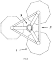
- Figures 1 to 3 identify the main parts comprised by the gravity-based foundation system for offshore wind turbine installation according to a first embodiment. These figures identify the following elements:
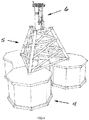
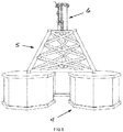
- FIGS. 4 to 6 show the main parts are identified comprised by the gravity-based foundation system for offshore wind turbine installation according to a second embodiment. These figures identify the following elements:
- the attachment of the metal structure (2, 5) to the three floating concrete bases (1, 4) is performed by means of mixed connecting nodes (7, 27), one for each floating concrete base (1, 4), each of which comprises a concrete core (8) and a prestressing system (9) integrated therein.
- the metal structure (2, 5) attaching the three floating concrete bases (1, 4) to the connecting element (3, 6) comprises three inclined diagonal rods (10) whose ends (11) which connect to each mixed connecting node (7, 27) are conical frustum-shaped which enables the appropriate adjustment of the mechanical constraints.
- the mixed connecting node (7, 27) further comprises a sheet metal coating (12) externally covering the concrete core (8), a metal coating (12) whose primary function is to assist in the transfer and resistance to the stresses caused by the forces introduced by the inclined diagonal rods (10) in the mixed connecting nodes (7, 27), although it also acts as a closure and protection element for the concrete core (8) used, to promote durability conditions thereof and, above all, of the working conditions of the prestressing system (9) situated in the mixed connecting node (7, 27) of the metal structure (2, 5) and the floating concrete base (1, 4).
- the mixed connecting node (7, 27) further comprises anchors that are actively involved in the transmission of forces, while the floating concrete base (1, 4) comprises passive anchors disposed in its interior, either directly in an upper closing slab (13) or in rigidity partition walls or interior walls situated under the mixed connecting nodes (not shown).
- the metal coating (12) of the mixed connecting node (7) has a polyhedral-like geometric shape with an upper prismatic-trapezoidal-shaped area (14) wherein one of the sides (15), the one that receives an inclined diagonal rod, is in turn inclined and perpendicular to the inclined diagonal rod, and a lower irregular prismatic-hexagonal-shaped area (16), wherein two of its vertical sides (17), which receive some first auxiliary rods (18) linking together two adjacent mixed connecting nodes (7) of each floating concrete base (1), are perpendicular to said first auxiliary rods (18), wherein the sides (15, 17) at which the inclined diagonal rod and the first auxiliary bars join are made of sheet steel.
- said mixed connecting core (7) receives, via the metal coating (12) with a tubular-like geometric shape, the inclined diagonal rod (10), the first auxiliary rods (18) linking together two adjacent mixed connecting nodes (7) of each floating concrete base (1) and the second auxiliary rod (20) joining the mixed connecting node (7) to the connecting element (3).
- the active anchors comprising:
- prestressing system (9) is also located inside the mixed connecting node (7),
- the node will then be concreted, preceded in the latter case by the concreting of a connection area between the mixed connecting node (7) and the floating concrete base (1), a connection area left as a control element with assembly and execution tolerances.
- the prestressing system (9) arranged inside the mixed connecting node (7) that penetrates the floating concrete base (1) is then prestressed, followed by the injection of the sheaths, and lastly the placing and welding of the metal coating (12) of the mixed connecting node (7) which encloses the concrete core (8).
- the mixed connecting node (27) has a metal coating (23) with a tubular-like geometrical shape arranged around a concrete core (24), wherein the metal coating (23) is a steel pipe section open at its upper end, to enable the concreting and the placing of the other elements described in the first embodiment of the mixed node (7).
- the mixed connecting core (27) receives, via the metal coating (23) with a tubular-like geometrical shape, the inclined diagonal rod (10), the first auxiliary rods (18) linking together the two adjacent mixed connecting nodes (27) of each floating concrete base (1) and the second auxiliary rod (20) which connects the mixed connecting node (27) to the connecting element (3).
- the transfer sheets (21) are situated, as well as the transfer and connection sheets (22), the prestressing system (9) and the passive anchors as described above.
- the gravity-based foundation system for offshore wind turbine installation further comprises a control system which in turn comprises a sensing subsystem (30), an operational control subsystem (31) and a decision-making subsystem (32) during the transport, anchoring, service and refloating stages, wherein the operative control subsystem enables the coordination between the sensing subsystems and decision-making support subsystem.
- the sensing subsystem (30) comprises filling level sensors (33) for the filling of the first group of cells whose function is to measure their ballasting level during the towing, anchoring and refloating stages. They are preferably situated on the lower slab.
- the sensing subsystem (30) further comprises inertial acceleration sensors (34) preferably placed on the upper slab of the caisson, in the mixed connection nodes joining and in the connection between the connecting element of the wind turbine and the metal structure. Their function is to measure the accelerations to avoid exceeding the possible thresholds set by the turbine manufacturer during the towing and anchoring stages.
- the sensing subsystem (30) further comprises Doppler acoustic sensors (35) for measuring currents in the vicinity of the structure and the distance to the seabed. Its function is to monitor the hydrodynamics surrounding the structure and to control the position of each caisson relative to the seabed in the anchoring stage and to support the erosion evolution characterization during the service stage. They are located at the point where the lower slab and the perimeter wall meet.
- the sensing subsystem (30) further comprises a gyro (36) to monitor the roll and pitch of each of the floating concrete bases (1, 4), which are preferably arranged in the centre of each floating concrete base. Its function is to control the verticality of the system during the towing and anchoring stages.
- the sensing subsystem (30) further comprises relative and absolute positioning sensors (37) to locate the system during transport and for its dynamic positioning during the anchoring stage. They are arranged on top of the metal structure.
- the sensing subsystem (30) further comprises pressure sensors (38) for the estimation of the actions resulting from the interaction between the flow of the sea and the structure during the service stage. They are preferably arranged embedded inside the perimeter walls of floating concrete bases.
- the sensing subsystem (30) further comprises deformation sensors (39) that enable the estimation of the number and magnitude of stress load cycles of the system due to its interaction with the ocean flow and / or cyclic stresses transmitted by the wind turbine. They are preferably arranged at the nodes of the metal structure and at the transition point between the metal structure and the floating concrete bases.
- the decision-making support subsystem (32) comprises a logical device (40) which is a first-level instrumental alarm to generate warnings to prevent exceeding the thresholds registered by the sensing subsystem, and a second-level prediction device (41) based on a climate prediction system (42) and on the instrumental historical records obtained by the different sensors (33, 34, 35, 36, 37, 38, 39), performing a real-time control (43) by the operational control subsystem (31) and may be displayed on a display device (44); an operational control subsystem (31) acting on the control actuators (45) that perform the opening and / or closing of the valves (46) for water filling and emptying and on a system of anchors and winches (47), to fix the position of the foundation system, generating response scenarios for the foundation system in the short and long term.
- a logical device 40
- a second-level prediction device (41) based on a climate prediction system (42) and on the instrumental historical records obtained by the different sensors (33, 34, 35, 36, 37, 38, 39)
Landscapes
- Engineering & Computer Science (AREA)
- Life Sciences & Earth Sciences (AREA)
- General Life Sciences & Earth Sciences (AREA)
- Mining & Mineral Resources (AREA)
- Paleontology (AREA)
- Civil Engineering (AREA)
- General Engineering & Computer Science (AREA)
- Structural Engineering (AREA)
- Wind Motors (AREA)
- Foundations (AREA)
Claims (13)
- Système de fondation gravitaire pour l'installation d'éoliennes offshore qui comprend :- trois bases en béton armé flottantes (1, 4) construites avec des caissons en béton auto-flottants, équipées de valves (46) pour les remplir d'eau et
les vider et permettant de réaliser leur ballastage et ancrage à leur emplacement définitif,- une structure métallique (2, 5) reliant les trois bases en béton flottantes (1, 4) à un mât éolien au moyen d'un élément de jonction, et- un élément métallique (3, 6) qui relie les bases en béton flottantes (1, 4) au mât éolien, élément métallique (3, 6) sur lequel sont installés un débarcadère, une plateforme de maintenance et des escaliers d'accès ;caractérisé en ce que la fixation de la structure métallique (2, 5) aux trois bases en béton flottantes (1, 4) est mise en oeuvre au moyen de modules de jonction mixtes (7, 27), un pour chaque base en béton flottante (1, 4), dont chacun comprend un noyau en béton (8, 24) et un système de précontrainte (9) intégré dans celui-ci. - Système de fondation gravitaire pour l'installation d'éoliennes offshore selon la revendication 1 dans lequel la structure métallique (2) est en forme de trépied.
- Système de fondation gravitaire pour l'installation d'éoliennes offshore selon la revendication 1 dans lequel la structure métallique (5) est en forme de treillis.
- Système de fondation gravitaire pour l'installation d'éoliennes offshore selon la revendication 1 dans lequel la structure métallique (2, 5) comprend trois tiges obliques (10) dont les extrémités (11) reliant chaque module de jonction mixte (7, 27) sont en forme de cône tronqué.
- Système de fondation gravitaire pour l'installation d'éoliennes offshore selon la revendication 4 dans lequel le module de jonction mixte (7, 27) comprend en outre un revêtement en tôle (12, 23) recouvrant l'extérieur du noyau en béton (8, 24).
- Système de fondation gravitaire pour l'installation d'éoliennes offshore selon la revendication 5 dans lequel le module de jonction mixte (7, 27) reçoit, par l'intermédiaire du revêtement en tôle (12, 23), la tige oblique (10), des premières tiges auxiliaires (18) reliant ensemble deux modules de jonction mixtes adjacents (7, 27) de chaque base en béton flottante (1) et une deuxième tige auxiliaire (20) reliant chaque module de jonction mixte (7, 27) à l'élément de jonction (3).
- Système de fondation gravitaire pour l'installation d'éoliennes offshore selon la revendication 6 dans lequel le revêtement en tôle (12) du module de jonction mixte (7) a une forme géométrique semblable à une forme polyédrique avec une partie supérieure en forme de prisme trapézoïdal (14) dans laquelle l'une de leurs faces (15), celle recevant une tige oblique (10), est à son tour inclinée et perpendiculaire à la tige oblique (10), et une partie inférieure irrégulière en forme de prisme hexagonal (16), dans laquelle deux de ses faces verticales (17), qui reçoivent des premières tiges auxiliaires (18) reliant deux modules de jonction mixtes adjacents (7) de chaque base en béton flottante (1), sont perpendiculaires auxdites premières tiges auxiliaires (18), dans laquelle les faces (15, 17) auxquelles sont reliées la tige oblique et les premières tiges auxiliaires sont en tôle.
- Système de fondation gravitaire pour l'installation d'éoliennes offshore selon la revendication 7 dans lequel la partie inférieure irrégulière en forme de prisme hexagonal (16) du module de jonction mixte (7) comprend une face verticale (19) située entre les deux faces verticales (17) recevant les premières tiges auxiliaires (18), dans laquelle ladite face verticale (19) reçoit la deuxième tige auxiliaire (20) qui relie le module de jonction mixte (7) à l'élément de jonction (3).
- Système de fondation gravitaire pour l'installation d'éoliennes offshore selon la revendication 6 dans lequel le revêtement en tôle (23) du module de jonction mixte (27) a une forme géométrique similaire à une forme tubulaire et le noyau en béton (24) est situé en son intérieur.
- Système de fondation gravitaire pour l'installation d'éoliennes offshore selon la revendication 6 dans lequel le module de jonction mixte (7, 27) comprend en outre des points d'ancrage actifs pour la transmission de forces, tandis que la base en béton flottante (1, 4) comprend des points d'ancrage passifs, situés soit directement sur une dalle de fermeture supérieure (13) soit sur des cloisons de séparation rigides se trouvant sous le module de jonction mixte (7, 27).
- Système de fondation gravitaire pour l'installation d'éoliennes offshore selon la revendication 10 dans lequel des points d'ancrage actifs sont placés dans le noyau en béton (8, 24), comprenant :• des feuilles de transfert (21) des quatre tiges (10, 18, 20) qui pénètrent le module de jonction mixte (7), dans lequel deux d'entre eux, la tige oblique (10) et la deuxième barre auxiliaire (20) sont reliées ensemble par soudage au point d'intersection des axes de toutes les tiges (10, 18, 20),• les feuilles de transfert et de jonction (22) reliant les premières tiges auxiliaires ensemble, eten outre, le système de précontrainte (9) est également situé dans le module de jonction mixte (7).
- Système de fondation gravitaire pour l'installation d'éoliennes offshore selon la revendication 1 dans lequel chacune des trois bases en béton flottantes (1, 4) comprend une dalle inférieure qui est en contact avec le sol une fois que le système a été submergé, une dalle supérieure (13), un mur périphérique et des parois ou cloisons internes délimitant un premier ensemble de cellules interconnectées.
- Procédé pour l'installation d'un système de fondation gravitaire d'éoliennes offshore selon l'une quelconque des revendications 1 à 12, le procédé comprenant les étapes suivantes :• une première étape de transport dans laquelle le système de fondation gravitaire est tracté en utilisant des remorqueurs du dock de collecte et/ou d'assemblage à l'emplacement définitif où les trois bases en béton flottantes (1, 4) sont ancrées,• une deuxième étape d'ancrage dans laquelle le système de fondation gravitaire est ancré jusqu'à ce qu'il soit en contact avec le fond marin modifiant la flottabilité globale par le ballastage contrôlé de certains groupes de cellules dans les trois bases en béton flottantes (1, 4) avec le fonctionnement de valves (46) situées dans lesdites bases, et• une troisième étape de remise à flot en cas de démantèlement ou de repositionnement du système de fondation gravitaire par l'évacuation des eaux de ballast des groupes de cellules préalablement ballastés afin d'obtenir une flottabilité positive du système de fondation gravitaire ;caractérisé en ce qu'il y a une série d'étapes de fabrication du système de fondation gravitaire avant la première étape de transport, comprenant :• une étape pour la fabrication des bases en béton flottantes (1, 4) dans un bassin portuaire en utilisant un quai flottant dans lequel est intégrée une saillie tubulaire en acier pour servir de jonction entre la structure métallique (2, 5) et les bases en béton (1, 4),• une étape pour la fabrication de la structure métallique (2, 5) à terre,• une étape pour la fabrication d'un élément métallique (3, 6) constituant la base de l'éolienne,• une étape pour relier ensemble la structure métallique (2, 5) aux bases en béton flottantes (1, 4) et pour souder l'élément métallique (3, 6) à la structure métallique (2, 5), et• une étape pour le montage de l'éolienne sur l'élément métallique.
Applications Claiming Priority (2)
| Application Number | Priority Date | Filing Date | Title |
|---|---|---|---|
| ES201200994A ES2452933B1 (es) | 2012-10-03 | 2012-10-03 | Sistema de cimentación por gravedad para la instalación de aerogeneradores offshore |
| PCT/ES2013/070339 WO2014053680A1 (fr) | 2012-10-03 | 2013-05-28 | Système de fondation par gravité pour l'installation d'éolienne marine et procédé d'installation d'une fondation de système d'éolienne marine |
Publications (2)
| Publication Number | Publication Date |
|---|---|
| EP2933381A1 EP2933381A1 (fr) | 2015-10-21 |
| EP2933381B1 true EP2933381B1 (fr) | 2018-07-18 |
Family
ID=49305011
Family Applications (1)
| Application Number | Title | Priority Date | Filing Date |
|---|---|---|---|
| EP13773817.5A Not-in-force EP2933381B1 (fr) | 2012-10-03 | 2013-05-28 | Système de fondation par gravité |
Country Status (5)
| Country | Link |
|---|---|
| US (1) | US9605401B2 (fr) |
| EP (1) | EP2933381B1 (fr) |
| CN (1) | CN104812963B (fr) |
| ES (2) | ES2452933B1 (fr) |
| WO (1) | WO2014053680A1 (fr) |
Cited By (1)
| Publication number | Priority date | Publication date | Assignee | Title |
|---|---|---|---|---|
| WO2023006955A1 (fr) | 2021-07-30 | 2023-02-02 | Lak Mohammad Amin | Fondation basée sur la gravité |
Families Citing this family (19)
| Publication number | Priority date | Publication date | Assignee | Title |
|---|---|---|---|---|
| US20190177995A1 (en) * | 2016-04-28 | 2019-06-13 | Voyageur Internet Inc. | Tower assembly with ballast receiving base |
| CN106017568B (zh) * | 2016-07-06 | 2018-12-25 | 沈阳建筑大学 | 预制装配式混凝土体系的结构健康监测系统及集成方法 |
| JP6575459B2 (ja) * | 2016-08-17 | 2019-09-18 | Jfeエンジニアリング株式会社 | 着床式基礎および着床式基礎の構築方法 |
| US10767632B2 (en) * | 2016-09-09 | 2020-09-08 | Siemens Gamesa Renewable Energy A/S | Transition piece for a wind turbine |
| GB201622129D0 (en) | 2016-12-23 | 2017-02-08 | Statoil Petroleum As | Subsea assembly modularisation |
| ES2617991B1 (es) * | 2017-02-14 | 2018-03-27 | Berenguer Ingenieros S.L. | Estructura marítima para la cimentación por gravedad de edificaciones, instalaciones y aerogeneradores en el medio marino |
| CN106869191A (zh) * | 2017-04-17 | 2017-06-20 | 中山市华蕴新能源科技有限公司 | 海上风机基础防冲刷保护装置及其系统 |
| PT110322A (pt) | 2017-10-03 | 2019-04-02 | Inst Superior Tecnico | Fundação para turbina eólica offshore de capacidade flutuante e com sistema de fixação por âncoras de sucção |
| KR101840649B1 (ko) * | 2017-11-20 | 2018-03-21 | 알렌 주식회사 | 해상 발전플랫폼의 부유시스템 |
| CN108374430A (zh) * | 2018-02-08 | 2018-08-07 | 中国能源建设集团江苏省电力设计院有限公司 | 一种海上全潜式基础与辅浮设备及施工方法 |
| CA180058S (en) * | 2018-03-02 | 2019-03-01 | John Rene Spronken | Crane base fastener |
| CN108639256A (zh) * | 2018-05-30 | 2018-10-12 | 西伯瀚(上海)海洋装备科技有限公司 | 一种海洋平台登艇装置及海洋平台 |
| ES2701605A1 (es) * | 2018-12-03 | 2019-02-25 | Hws Concrete Towers S L | Cimentacion para torres eolicas |
| US10634122B1 (en) * | 2019-02-08 | 2020-04-28 | Are Telecom Incorporated | Portable monopole tower with adjustable foundation |
| ES2796978B2 (es) * | 2019-05-31 | 2022-07-13 | Esteyco S A | Procedimiento para el mantenimiento de torres eolicas mediante sistemas flotantes auxiliares |
| FR3108953B1 (fr) | 2020-04-06 | 2023-07-21 | Olivier Juin | Structure porteuse d’installation de modules de captage d’energie eolienne |
| DK202070470A1 (en) | 2020-07-08 | 2022-01-18 | Stiesdal Offshore Tech A/S | Structure with grouted joints and a method of forming such joint |
| KR20240004955A (ko) | 2021-05-06 | 2024-01-11 | 프리드 앤드 골드만, 엘엘씨 디/비/에이 프리드 앤드 골드만, 엘티디. | 해상 자기-엘리베이팅 선박과 함께 사용하도록 구성된 수송 선박용 랙 구조물을 위한 시스템들 및 방법들 |
| JP7430859B1 (ja) | 2022-07-27 | 2024-02-14 | 株式会社 セテック | 浮体式洋上風力発電システム |
Family Cites Families (16)
| Publication number | Priority date | Publication date | Assignee | Title |
|---|---|---|---|---|
| US3653219A (en) * | 1969-12-31 | 1972-04-04 | Texaco Inc | Marine platform |
| JPS532242B2 (fr) * | 1974-12-24 | 1978-01-26 | ||
| AU1193583A (en) * | 1982-03-05 | 1983-09-08 | Heerema Engineering Service B.V. | Offshore tower |
| SE445473B (sv) * | 1984-11-09 | 1986-06-23 | Offshore Ab J & W | Grundleggningselement foretredesvis avsett for undervattensbruk och anvendning av detta |
| US4821804A (en) * | 1985-03-27 | 1989-04-18 | Pierce Robert H | Composite support column assembly for offshore drilling and production platforms |
| AU757367B2 (en) * | 1998-04-02 | 2003-02-20 | Suction Pile Technology B.V. | Marine structure |
| DE20100588U1 (de) * | 2001-01-13 | 2001-03-22 | Briese Remmer | Off-Shore-Windkraftanlage |
| DE102005014868A1 (de) * | 2005-03-30 | 2006-10-05 | Repower Systems Ag | Offshore-Windenergieanlage mit rutschfesten Füßen |
| ITTO20070666A1 (it) * | 2007-09-24 | 2009-03-25 | Blue H Intellectual Properties | Sistema di conversione di energia eolica offshore per acque profonde |
| NO330530B1 (no) * | 2009-06-10 | 2011-05-09 | Seatower As | Anordning og fremgangsmate for understottelse av en vindturbin eller lignende |
| DE102010009466A1 (de) | 2010-02-26 | 2011-09-01 | Ed. Züblin Aktiengesellschaft | Vorrichtung zum Transport und Installieren von eine Flachgründung umfassende Anordnung einer Offshore-Windenergieanlage sowie Verfahren zum Transport und zur Installation einer solchen Anordnung mit Flachgründung |
| WO2011147482A1 (fr) | 2010-05-28 | 2011-12-01 | Siemens Aktiengesellschaft | Ancre de sol, fondation en mer utilisant une ancre de sol et procédé d'établissement d'une fondation en mer |
| CN201746849U (zh) * | 2010-06-24 | 2011-02-16 | 上海勘测设计研究院 | 海上风电场风机基础结构 |
| DE202011101599U1 (de) * | 2011-05-12 | 2011-09-23 | Emilio Reales Bertomeo | Offshore-Fundament für Windenergieanlagen |
| CN102268879B (zh) * | 2011-05-25 | 2015-12-09 | 江苏道达海上风电工程科技有限公司 | 海上测风塔的基础结构及其安装方法 |
| CN102587405A (zh) * | 2012-02-27 | 2012-07-18 | 广东明阳风电产业集团有限公司 | 海上风机导管架基础安装方法及分离式导管架装置 |
-
2012
- 2012-10-03 ES ES201200994A patent/ES2452933B1/es not_active Expired - Fee Related
-
2013
- 2013-05-28 US US14/427,230 patent/US9605401B2/en not_active Expired - Fee Related
- 2013-05-28 CN CN201380051497.3A patent/CN104812963B/zh not_active Expired - Fee Related
- 2013-05-28 ES ES13773817.5T patent/ES2693719T3/es active Active
- 2013-05-28 EP EP13773817.5A patent/EP2933381B1/fr not_active Not-in-force
- 2013-05-28 WO PCT/ES2013/070339 patent/WO2014053680A1/fr active Application Filing
Non-Patent Citations (1)
| Title |
|---|
| None * |
Cited By (1)
| Publication number | Priority date | Publication date | Assignee | Title |
|---|---|---|---|---|
| WO2023006955A1 (fr) | 2021-07-30 | 2023-02-02 | Lak Mohammad Amin | Fondation basée sur la gravité |
Also Published As
| Publication number | Publication date |
|---|---|
| CN104812963A (zh) | 2015-07-29 |
| US20150240442A1 (en) | 2015-08-27 |
| ES2452933A1 (es) | 2014-04-03 |
| ES2452933B1 (es) | 2015-03-09 |
| WO2014053680A1 (fr) | 2014-04-10 |
| EP2933381A1 (fr) | 2015-10-21 |
| ES2693719T3 (es) | 2018-12-13 |
| US9605401B2 (en) | 2017-03-28 |
| CN104812963B (zh) | 2017-10-13 |
Similar Documents
| Publication | Publication Date | Title |
|---|---|---|
| EP2933381B1 (fr) | Système de fondation par gravité | |
| EP2837554A1 (fr) | Plateforme marine partiellement flottante pour éoliennes en mer, ponts et constructions maritimes, et procédé de fabrication | |
| CN110382781B (zh) | 用于在海洋环境中利用重力铺设建筑物、设备和风力涡轮机的基础的海事结构 | |
| JP2020514181A (ja) | 浮体式海洋プラットフォーム | |
| ES2387342B2 (es) | Plataforma semisumergible triángular para aplicaciones en mar abierto | |
| KR20110030628A (ko) | 근해 풍력 기지 산업에 이용하기 위한 지지 구조물 | |
| JP2014515446A (ja) | エネルギー貯蔵設備を備えた浮体式風力発電施設 | |
| CN102015435A (zh) | 用于支撑近海风力涡轮机的不对称系泊系统和带有水收集板的支柱稳定式近海平台 | |
| CN106812144A (zh) | 双壁钢围堰施工方法 | |
| CN110939148A (zh) | 一种兼做钻孔平台的双壁钢吊箱围堰施工方法 | |
| NL2028088B1 (en) | Concrete connector body for an offshore wind turbine. | |
| CN110735394B (zh) | 索塔结构及其建造方法 | |
| US11920559B2 (en) | Floating platform for high-power wind turbines | |
| CN202969333U (zh) | 钢桁架嵌岩码头结构 | |
| JP6105044B2 (ja) | 海上風力、橋および海上建造物用部分浮体式海上プラットホーム、および施工方法 | |
| JP2010180684A (ja) | 立体ラーメン構造の桟橋と施工方法 | |
| CN201292535Y (zh) | 深海裸岩墩护筒、定位桩、水下围堰一体化平台 | |
| CN201362844Y (zh) | 一种适用于海上无覆盖层情况下的钻孔施工平台 | |
| CN218969958U (zh) | 装配式海洋平台模块及海洋平台 | |
| CN219364546U (zh) | 预制式海洋平台 | |
| CN108797348A (zh) | 复合式单壁钢套箱装置及其施工方法 | |
| CN214574092U (zh) | 潮水中承台混凝土预制拼装封底结构 | |
| WO2023006955A1 (fr) | Fondation basée sur la gravité | |
| JP2024057389A (ja) | 浮体式洋上風力発電用下部構造、及び浮体式洋上風力発電用下部構造の施工方法 | |
| CN112627219A (zh) | 潮水中承台混凝土预制拼装封底结构及其施工工艺 |
Legal Events
| Date | Code | Title | Description |
|---|---|---|---|
| PUAI | Public reference made under article 153(3) epc to a published international application that has entered the european phase |
Free format text: ORIGINAL CODE: 0009012 |
|
| PUAB | Information related to the publication of an a document modified or deleted |
Free format text: ORIGINAL CODE: 0009199EPPU |
|
| PUAI | Public reference made under article 153(3) epc to a published international application that has entered the european phase |
Free format text: ORIGINAL CODE: 0009012 |
|
| 17P | Request for examination filed |
Effective date: 20150401 |
|
| AK | Designated contracting states |
Kind code of ref document: A1 Designated state(s): AL AT BE BG CH CY CZ DE DK EE ES FI FR GB GR HR HU IE IS IT LI LT LU LV MC MK MT NL NO PL PT RO RS SE SI SK SM TR |
|
| AX | Request for extension of the european patent |
Extension state: BA ME |
|
| DAX | Request for extension of the european patent (deleted) | ||
| 17Q | First examination report despatched |
Effective date: 20160530 |
|
| STAA | Information on the status of an ep patent application or granted ep patent |
Free format text: STATUS: EXAMINATION IS IN PROGRESS |
|
| GRAP | Despatch of communication of intention to grant a patent |
Free format text: ORIGINAL CODE: EPIDOSNIGR1 |
|
| STAA | Information on the status of an ep patent application or granted ep patent |
Free format text: STATUS: GRANT OF PATENT IS INTENDED |
|
| INTG | Intention to grant announced |
Effective date: 20180307 |
|
| GRAS | Grant fee paid |
Free format text: ORIGINAL CODE: EPIDOSNIGR3 |
|
| GRAA | (expected) grant |
Free format text: ORIGINAL CODE: 0009210 |
|
| STAA | Information on the status of an ep patent application or granted ep patent |
Free format text: STATUS: THE PATENT HAS BEEN GRANTED |
|
| AK | Designated contracting states |
Kind code of ref document: B1 Designated state(s): AL AT BE BG CH CY CZ DE DK EE ES FI FR GB GR HR HU IE IS IT LI LT LU LV MC MK MT NL NO PL PT RO RS SE SI SK SM TR |
|
| REG | Reference to a national code |
Ref country code: GB Ref legal event code: FG4D |
|
| REG | Reference to a national code |
Ref country code: CH Ref legal event code: EP |
|
| REG | Reference to a national code |
Ref country code: IE Ref legal event code: FG4D |
|
| REG | Reference to a national code |
Ref country code: AT Ref legal event code: REF Ref document number: 1019510 Country of ref document: AT Kind code of ref document: T Effective date: 20180815 |
|
| REG | Reference to a national code |
Ref country code: DE Ref legal event code: R096 Ref document number: 602013040512 Country of ref document: DE |
|
| REG | Reference to a national code |
Ref country code: NL Ref legal event code: MP Effective date: 20180718 |
|
| REG | Reference to a national code |
Ref country code: LT Ref legal event code: MG4D |
|
| REG | Reference to a national code |
Ref country code: ES Ref legal event code: FG2A Ref document number: 2693719 Country of ref document: ES Kind code of ref document: T3 Effective date: 20181213 |
|
| REG | Reference to a national code |
Ref country code: AT Ref legal event code: MK05 Ref document number: 1019510 Country of ref document: AT Kind code of ref document: T Effective date: 20180718 |
|
| PG25 | Lapsed in a contracting state [announced via postgrant information from national office to epo] |
Ref country code: NL Free format text: LAPSE BECAUSE OF FAILURE TO SUBMIT A TRANSLATION OF THE DESCRIPTION OR TO PAY THE FEE WITHIN THE PRESCRIBED TIME-LIMIT Effective date: 20180718 |
|
| PG25 | Lapsed in a contracting state [announced via postgrant information from national office to epo] |
Ref country code: GR Free format text: LAPSE BECAUSE OF FAILURE TO SUBMIT A TRANSLATION OF THE DESCRIPTION OR TO PAY THE FEE WITHIN THE PRESCRIBED TIME-LIMIT Effective date: 20181019 Ref country code: NO Free format text: LAPSE BECAUSE OF FAILURE TO SUBMIT A TRANSLATION OF THE DESCRIPTION OR TO PAY THE FEE WITHIN THE PRESCRIBED TIME-LIMIT Effective date: 20181018 Ref country code: FI Free format text: LAPSE BECAUSE OF FAILURE TO SUBMIT A TRANSLATION OF THE DESCRIPTION OR TO PAY THE FEE WITHIN THE PRESCRIBED TIME-LIMIT Effective date: 20180718 Ref country code: AT Free format text: LAPSE BECAUSE OF FAILURE TO SUBMIT A TRANSLATION OF THE DESCRIPTION OR TO PAY THE FEE WITHIN THE PRESCRIBED TIME-LIMIT Effective date: 20180718 Ref country code: LT Free format text: LAPSE BECAUSE OF FAILURE TO SUBMIT A TRANSLATION OF THE DESCRIPTION OR TO PAY THE FEE WITHIN THE PRESCRIBED TIME-LIMIT Effective date: 20180718 Ref country code: RS Free format text: LAPSE BECAUSE OF FAILURE TO SUBMIT A TRANSLATION OF THE DESCRIPTION OR TO PAY THE FEE WITHIN THE PRESCRIBED TIME-LIMIT Effective date: 20180718 Ref country code: PL Free format text: LAPSE BECAUSE OF FAILURE TO SUBMIT A TRANSLATION OF THE DESCRIPTION OR TO PAY THE FEE WITHIN THE PRESCRIBED TIME-LIMIT Effective date: 20180718 Ref country code: IS Free format text: LAPSE BECAUSE OF FAILURE TO SUBMIT A TRANSLATION OF THE DESCRIPTION OR TO PAY THE FEE WITHIN THE PRESCRIBED TIME-LIMIT Effective date: 20181118 Ref country code: BG Free format text: LAPSE BECAUSE OF FAILURE TO SUBMIT A TRANSLATION OF THE DESCRIPTION OR TO PAY THE FEE WITHIN THE PRESCRIBED TIME-LIMIT Effective date: 20181018 Ref country code: SE Free format text: LAPSE BECAUSE OF FAILURE TO SUBMIT A TRANSLATION OF THE DESCRIPTION OR TO PAY THE FEE WITHIN THE PRESCRIBED TIME-LIMIT Effective date: 20180718 |
|
| PG25 | Lapsed in a contracting state [announced via postgrant information from national office to epo] |
Ref country code: LV Free format text: LAPSE BECAUSE OF FAILURE TO SUBMIT A TRANSLATION OF THE DESCRIPTION OR TO PAY THE FEE WITHIN THE PRESCRIBED TIME-LIMIT Effective date: 20180718 Ref country code: AL Free format text: LAPSE BECAUSE OF FAILURE TO SUBMIT A TRANSLATION OF THE DESCRIPTION OR TO PAY THE FEE WITHIN THE PRESCRIBED TIME-LIMIT Effective date: 20180718 Ref country code: HR Free format text: LAPSE BECAUSE OF FAILURE TO SUBMIT A TRANSLATION OF THE DESCRIPTION OR TO PAY THE FEE WITHIN THE PRESCRIBED TIME-LIMIT Effective date: 20180718 |
|
| REG | Reference to a national code |
Ref country code: DE Ref legal event code: R097 Ref document number: 602013040512 Country of ref document: DE |
|
| PG25 | Lapsed in a contracting state [announced via postgrant information from national office to epo] |
Ref country code: CZ Free format text: LAPSE BECAUSE OF FAILURE TO SUBMIT A TRANSLATION OF THE DESCRIPTION OR TO PAY THE FEE WITHIN THE PRESCRIBED TIME-LIMIT Effective date: 20180718 Ref country code: RO Free format text: LAPSE BECAUSE OF FAILURE TO SUBMIT A TRANSLATION OF THE DESCRIPTION OR TO PAY THE FEE WITHIN THE PRESCRIBED TIME-LIMIT Effective date: 20180718 Ref country code: EE Free format text: LAPSE BECAUSE OF FAILURE TO SUBMIT A TRANSLATION OF THE DESCRIPTION OR TO PAY THE FEE WITHIN THE PRESCRIBED TIME-LIMIT Effective date: 20180718 Ref country code: IT Free format text: LAPSE BECAUSE OF FAILURE TO SUBMIT A TRANSLATION OF THE DESCRIPTION OR TO PAY THE FEE WITHIN THE PRESCRIBED TIME-LIMIT Effective date: 20180718 |
|
| PLBE | No opposition filed within time limit |
Free format text: ORIGINAL CODE: 0009261 |
|
| STAA | Information on the status of an ep patent application or granted ep patent |
Free format text: STATUS: NO OPPOSITION FILED WITHIN TIME LIMIT |
|
| PG25 | Lapsed in a contracting state [announced via postgrant information from national office to epo] |
Ref country code: SM Free format text: LAPSE BECAUSE OF FAILURE TO SUBMIT A TRANSLATION OF THE DESCRIPTION OR TO PAY THE FEE WITHIN THE PRESCRIBED TIME-LIMIT Effective date: 20180718 Ref country code: SK Free format text: LAPSE BECAUSE OF FAILURE TO SUBMIT A TRANSLATION OF THE DESCRIPTION OR TO PAY THE FEE WITHIN THE PRESCRIBED TIME-LIMIT Effective date: 20180718 Ref country code: DK Free format text: LAPSE BECAUSE OF FAILURE TO SUBMIT A TRANSLATION OF THE DESCRIPTION OR TO PAY THE FEE WITHIN THE PRESCRIBED TIME-LIMIT Effective date: 20180718 |
|
| 26N | No opposition filed |
Effective date: 20190423 |
|
| PGFP | Annual fee paid to national office [announced via postgrant information from national office to epo] |
Ref country code: ES Payment date: 20190611 Year of fee payment: 7 |
|
| PG25 | Lapsed in a contracting state [announced via postgrant information from national office to epo] |
Ref country code: SI Free format text: LAPSE BECAUSE OF FAILURE TO SUBMIT A TRANSLATION OF THE DESCRIPTION OR TO PAY THE FEE WITHIN THE PRESCRIBED TIME-LIMIT Effective date: 20180718 |
|
| REG | Reference to a national code |
Ref country code: DE Ref legal event code: R119 Ref document number: 602013040512 Country of ref document: DE |
|
| REG | Reference to a national code |
Ref country code: CH Ref legal event code: PL |
|
| GBPC | Gb: european patent ceased through non-payment of renewal fee |
Effective date: 20190528 |
|
| PG25 | Lapsed in a contracting state [announced via postgrant information from national office to epo] |
Ref country code: LI Free format text: LAPSE BECAUSE OF NON-PAYMENT OF DUE FEES Effective date: 20190531 Ref country code: MC Free format text: LAPSE BECAUSE OF FAILURE TO SUBMIT A TRANSLATION OF THE DESCRIPTION OR TO PAY THE FEE WITHIN THE PRESCRIBED TIME-LIMIT Effective date: 20180718 Ref country code: CH Free format text: LAPSE BECAUSE OF NON-PAYMENT OF DUE FEES Effective date: 20190531 |
|
| REG | Reference to a national code |
Ref country code: BE Ref legal event code: MM Effective date: 20190531 |
|
| PG25 | Lapsed in a contracting state [announced via postgrant information from national office to epo] |
Ref country code: LU Free format text: LAPSE BECAUSE OF NON-PAYMENT OF DUE FEES Effective date: 20190528 |
|
| PG25 | Lapsed in a contracting state [announced via postgrant information from national office to epo] |
Ref country code: TR Free format text: LAPSE BECAUSE OF FAILURE TO SUBMIT A TRANSLATION OF THE DESCRIPTION OR TO PAY THE FEE WITHIN THE PRESCRIBED TIME-LIMIT Effective date: 20180718 |
|
| PG25 | Lapsed in a contracting state [announced via postgrant information from national office to epo] |
Ref country code: GB Free format text: LAPSE BECAUSE OF NON-PAYMENT OF DUE FEES Effective date: 20190528 Ref country code: DE Free format text: LAPSE BECAUSE OF NON-PAYMENT OF DUE FEES Effective date: 20191203 Ref country code: IE Free format text: LAPSE BECAUSE OF NON-PAYMENT OF DUE FEES Effective date: 20190528 |
|
| PG25 | Lapsed in a contracting state [announced via postgrant information from national office to epo] |
Ref country code: BE Free format text: LAPSE BECAUSE OF NON-PAYMENT OF DUE FEES Effective date: 20190531 |
|
| PG25 | Lapsed in a contracting state [announced via postgrant information from national office to epo] |
Ref country code: FR Free format text: LAPSE BECAUSE OF NON-PAYMENT OF DUE FEES Effective date: 20190531 Ref country code: PT Free format text: LAPSE BECAUSE OF FAILURE TO SUBMIT A TRANSLATION OF THE DESCRIPTION OR TO PAY THE FEE WITHIN THE PRESCRIBED TIME-LIMIT Effective date: 20181118 |
|
| PG25 | Lapsed in a contracting state [announced via postgrant information from national office to epo] |
Ref country code: CY Free format text: LAPSE BECAUSE OF FAILURE TO SUBMIT A TRANSLATION OF THE DESCRIPTION OR TO PAY THE FEE WITHIN THE PRESCRIBED TIME-LIMIT Effective date: 20180718 |
|
| PG25 | Lapsed in a contracting state [announced via postgrant information from national office to epo] |
Ref country code: MT Free format text: LAPSE BECAUSE OF FAILURE TO SUBMIT A TRANSLATION OF THE DESCRIPTION OR TO PAY THE FEE WITHIN THE PRESCRIBED TIME-LIMIT Effective date: 20180718 Ref country code: HU Free format text: LAPSE BECAUSE OF FAILURE TO SUBMIT A TRANSLATION OF THE DESCRIPTION OR TO PAY THE FEE WITHIN THE PRESCRIBED TIME-LIMIT; INVALID AB INITIO Effective date: 20130528 |
|
| REG | Reference to a national code |
Ref country code: ES Ref legal event code: FD2A Effective date: 20211006 |
|
| PG25 | Lapsed in a contracting state [announced via postgrant information from national office to epo] |
Ref country code: ES Free format text: LAPSE BECAUSE OF NON-PAYMENT OF DUE FEES Effective date: 20200529 |
|
| PG25 | Lapsed in a contracting state [announced via postgrant information from national office to epo] |
Ref country code: MK Free format text: LAPSE BECAUSE OF FAILURE TO SUBMIT A TRANSLATION OF THE DESCRIPTION OR TO PAY THE FEE WITHIN THE PRESCRIBED TIME-LIMIT Effective date: 20180718 |