EP2932924A1 - Vibrierende chirurgische Instrumente zur stumpfen Dissektion - Google Patents
Vibrierende chirurgische Instrumente zur stumpfen Dissektion Download PDFInfo
- Publication number
- EP2932924A1 EP2932924A1 EP14199666.0A EP14199666A EP2932924A1 EP 2932924 A1 EP2932924 A1 EP 2932924A1 EP 14199666 A EP14199666 A EP 14199666A EP 2932924 A1 EP2932924 A1 EP 2932924A1
- Authority
- EP
- European Patent Office
- Prior art keywords
- dissector
- distal end
- arm
- string
- arms
- Prior art date
- Legal status (The legal status is an assumption and is not a legal conclusion. Google has not performed a legal analysis and makes no representation as to the accuracy of the status listed.)
- Granted
Links
- 238000002224 dissection Methods 0.000 title description 13
- 230000007246 mechanism Effects 0.000 claims description 51
- 230000010355 oscillation Effects 0.000 claims description 30
- 230000007704 transition Effects 0.000 claims description 8
- 235000017060 Arachis glabrata Nutrition 0.000 description 33
- 241001553178 Arachis glabrata Species 0.000 description 33
- 235000010777 Arachis hypogaea Nutrition 0.000 description 33
- 235000018262 Arachis monticola Nutrition 0.000 description 33
- 235000020232 peanut Nutrition 0.000 description 33
- 238000000034 method Methods 0.000 description 16
- 238000001356 surgical procedure Methods 0.000 description 4
- 208000014674 injury Diseases 0.000 description 3
- 238000000926 separation method Methods 0.000 description 3
- 208000027418 Wounds and injury Diseases 0.000 description 2
- 230000008901 benefit Effects 0.000 description 2
- 210000004204 blood vessel Anatomy 0.000 description 2
- 230000006378 damage Effects 0.000 description 2
- 230000001939 inductive effect Effects 0.000 description 2
- 210000000056 organ Anatomy 0.000 description 2
- 230000002745 absorbent Effects 0.000 description 1
- 239000002250 absorbent Substances 0.000 description 1
- 239000008280 blood Substances 0.000 description 1
- 210000004369 blood Anatomy 0.000 description 1
- 239000012530 fluid Substances 0.000 description 1
- 239000000463 material Substances 0.000 description 1
- 238000012986 modification Methods 0.000 description 1
- 230000004048 modification Effects 0.000 description 1
- 230000008733 trauma Effects 0.000 description 1
Images


Classifications
-
- A—HUMAN NECESSITIES
- A61—MEDICAL OR VETERINARY SCIENCE; HYGIENE
- A61B—DIAGNOSIS; SURGERY; IDENTIFICATION
- A61B17/00—Surgical instruments, devices or methods
- A61B17/32—Surgical cutting instruments
- A61B17/320068—Surgical cutting instruments using mechanical vibrations, e.g. ultrasonic
-
- A—HUMAN NECESSITIES
- A61—MEDICAL OR VETERINARY SCIENCE; HYGIENE
- A61B—DIAGNOSIS; SURGERY; IDENTIFICATION
- A61B17/00—Surgical instruments, devices or methods
- A61B17/32—Surgical cutting instruments
- A61B17/320068—Surgical cutting instruments using mechanical vibrations, e.g. ultrasonic
- A61B17/320092—Surgical cutting instruments using mechanical vibrations, e.g. ultrasonic with additional movable means for clamping or cutting tissue, e.g. with a pivoting jaw
-
- A—HUMAN NECESSITIES
- A61—MEDICAL OR VETERINARY SCIENCE; HYGIENE
- A61B—DIAGNOSIS; SURGERY; IDENTIFICATION
- A61B17/00—Surgical instruments, devices or methods
- A61B17/32—Surgical cutting instruments
- A61B17/3205—Excision instruments
- A61B17/32056—Surgical snare instruments
-
- A—HUMAN NECESSITIES
- A61—MEDICAL OR VETERINARY SCIENCE; HYGIENE
- A61B—DIAGNOSIS; SURGERY; IDENTIFICATION
- A61B17/00—Surgical instruments, devices or methods
- A61B17/22—Implements for squeezing-off ulcers or the like on inner organs of the body; Implements for scraping-out cavities of body organs, e.g. bones; for invasive removal or destruction of calculus using mechanical vibrations; for removing obstructions in blood vessels, not otherwise provided for
- A61B17/22004—Implements for squeezing-off ulcers or the like on inner organs of the body; Implements for scraping-out cavities of body organs, e.g. bones; for invasive removal or destruction of calculus using mechanical vibrations; for removing obstructions in blood vessels, not otherwise provided for using mechanical vibrations, e.g. ultrasonic shock waves
-
- A—HUMAN NECESSITIES
- A61—MEDICAL OR VETERINARY SCIENCE; HYGIENE
- A61B—DIAGNOSIS; SURGERY; IDENTIFICATION
- A61B17/00—Surgical instruments, devices or methods
- A61B17/32—Surgical cutting instruments
- A61B17/320016—Endoscopic cutting instruments, e.g. arthroscopes, resectoscopes
- A61B17/32002—Endoscopic cutting instruments, e.g. arthroscopes, resectoscopes with continuously rotating, oscillating or reciprocating cutting instruments
-
- A—HUMAN NECESSITIES
- A61—MEDICAL OR VETERINARY SCIENCE; HYGIENE
- A61B—DIAGNOSIS; SURGERY; IDENTIFICATION
- A61B17/00—Surgical instruments, devices or methods
- A61B2017/00367—Details of actuation of instruments, e.g. relations between pushing buttons, or the like, and activation of the tool, working tip, or the like
- A61B2017/00398—Details of actuation of instruments, e.g. relations between pushing buttons, or the like, and activation of the tool, working tip, or the like using powered actuators, e.g. stepper motors, solenoids
- A61B2017/00402—Piezo electric actuators
-
- A—HUMAN NECESSITIES
- A61—MEDICAL OR VETERINARY SCIENCE; HYGIENE
- A61B—DIAGNOSIS; SURGERY; IDENTIFICATION
- A61B17/00—Surgical instruments, devices or methods
- A61B2017/00367—Details of actuation of instruments, e.g. relations between pushing buttons, or the like, and activation of the tool, working tip, or the like
- A61B2017/00415—Details of actuation of instruments, e.g. relations between pushing buttons, or the like, and activation of the tool, working tip, or the like having power generation near the working tip of the tool
-
- A—HUMAN NECESSITIES
- A61—MEDICAL OR VETERINARY SCIENCE; HYGIENE
- A61B—DIAGNOSIS; SURGERY; IDENTIFICATION
- A61B17/00—Surgical instruments, devices or methods
- A61B2017/00831—Material properties
- A61B2017/00876—Material properties magnetic
-
- A—HUMAN NECESSITIES
- A61—MEDICAL OR VETERINARY SCIENCE; HYGIENE
- A61B—DIAGNOSIS; SURGERY; IDENTIFICATION
- A61B17/00—Surgical instruments, devices or methods
- A61B17/32—Surgical cutting instruments
- A61B2017/320044—Blunt dissectors
-
- A—HUMAN NECESSITIES
- A61—MEDICAL OR VETERINARY SCIENCE; HYGIENE
- A61B—DIAGNOSIS; SURGERY; IDENTIFICATION
- A61B17/00—Surgical instruments, devices or methods
- A61B17/32—Surgical cutting instruments
- A61B2017/32006—Surgical cutting instruments with a cutting strip, band or chain, e.g. like a chainsaw
-
- A—HUMAN NECESSITIES
- A61—MEDICAL OR VETERINARY SCIENCE; HYGIENE
- A61B—DIAGNOSIS; SURGERY; IDENTIFICATION
- A61B17/00—Surgical instruments, devices or methods
- A61B17/32—Surgical cutting instruments
- A61B17/320068—Surgical cutting instruments using mechanical vibrations, e.g. ultrasonic
- A61B2017/320071—Surgical cutting instruments using mechanical vibrations, e.g. ultrasonic with articulating means for working tip
-
- A—HUMAN NECESSITIES
- A61—MEDICAL OR VETERINARY SCIENCE; HYGIENE
- A61B—DIAGNOSIS; SURGERY; IDENTIFICATION
- A61B17/00—Surgical instruments, devices or methods
- A61B17/32—Surgical cutting instruments
- A61B17/320068—Surgical cutting instruments using mechanical vibrations, e.g. ultrasonic
- A61B2017/320072—Working tips with special features, e.g. extending parts
- A61B2017/320078—Tissue manipulating surface
Definitions
- the present disclosure relates to surgical instruments and, more specifically, to vibrating surgical instruments for blunt dissection of tissue.
- tissue to be removed various different types are desirable.
- the most common type of surgical tool to remove tissue is undoubtedly a sharp device such as a scalpel, blade, saw, or drill.
- a sharp device such as a scalpel, blade, saw, or drill.
- These types of devices are necessary for virtually any type of surgery to be performed as they allow the surgeon to cut through what would otherwise be a seamless body structure. In many situations, however, they are preferably not used as should the cutting instrument slip slightly, a dangerous situation could occur.
- misplacement or deviation of a sharp device can result in potential injury.
- One way to avoid this type of injury is to utilize a tool that is suitable for separating two types of matter along an existing seam or connection, but is generally unsuitable for "cutting" into seamless matter.
- This is often referred to as a blunt dissection instrument.
- Blunt dissection generally allows tissues to be dissected atraumatically by simply separating the tissue along existing seams or natural planes. That is, the tool separates along natural separations, conjunctions, or faults, without the tool creating a new seam.
- This type of instrument facilitates in surgical exposure and tissue retraction both because of reducing danger to neighboring tissue and reducing trauma from manmade separation.
- blunt dissection is a useful medical procedure
- the tools for blunt dissection are often ill suited for the task.
- Current tools may not provide sufficient force to separate structures without an existing seam and are generally incapable of generating a new seam or separation on its own.
- a dissector in an aspect of the present disclosure, includes a body, a first arm, a second arm, and a string.
- the first arm extends from the body to a first distal end and the second arm extends from the body to a second distal end.
- One end of the string is coupled to the first arm adjacent the first distal end and the other end of the string is coupled to the second arm adjacent the second distal end.
- the string is taut when the first and second arms are in the expanded configuration and the string is slack when the first and second arms are in a collapsed configuration.
- the string is configured to dissect tissue when the first and second arms are in the expanded configuration.
- first and second distal ends are configured to atraumatically dissect tissue.
- the first and second arms may be biased towards the expanded configuration.
- the dissector includes a tube that defines a lumen.
- the body of the dissector may be slidably disposed within the lumen such that the first and second arms extend from a distal end of the tube in the expanded configuration and are at least partially disposed within the lumen in the collapsed configuration.
- the tube may engage the first and second arms to transition the first and second arms from the expanded configuration to the collapsed configuration.
- the first and second distal ends protrude from a distal end of the tube to atraumatically dissect tissue.
- the first and second arms may have a transport configuration such that the first and second distal ends are disposed within the lumen proximal to a distal end of the tube.
- first and second distal ends may protrude from a distal end of the body to atraumatically dissect tissue.
- the first and second arms may have a transport configuration such that the first and second distal ends are disposed within the body proximal to a distal end of the body.
- the first and second arms are coupled together and to the body by a pivot pin.
- the body may define a slot defined in sidewalls of the body parallel to a longitudinal axis of the body.
- the pivot pin may be slidably disposed within the slot.
- the dissector may include a biasing member disposed about the pivot pint that biases the first and second arms towards the expanded configuration.
- the biasing member may be a torsion spring.
- the dissector includes a retraction member coupled to the pivot pin. The retraction member may be configured to retract the pivot pin towards a proximal end of the slot.
- the dissector includes a vibration mechanism that is configured to oscillate the string traverse to or along a longitudinal axis of the body.
- the dissector may include first and second jaw members coupled together at a pivot pin.
- the first distal end of the first arm may be disposed within the first jaw member and the second distal end of the second arm may be disposed within the second jaw member.
- the distal ends of the first and second jaw members may be configured to atraumatically dissect tissue.
- the first and second jaw member may be configured to limit tissue contacting the string when the first and second arms are in the expanded configuration. Proximal portions of the first and second arms may extend proximally within the body.
- a vibration mechanism may be disposed within the first jaw member.
- the vibration mechanism includes a magnetic coil and a magnet.
- the magnet may be disposed on the first arm adjacent the first distal end and the magnetic coil may be positioned adjacent the magnet.
- the magnetic coil is configured to alternately attract and repel the magnet as energy is applied to the magnetic coil such that the string is oscillated.
- the vibration mechanism includes a rotary element and an eccentric mass.
- the rotary element is disposed on the first arm adjacent the first distal end.
- the eccentric mass is rotatable by the rotary element to induce oscillation of the string.
- the vibration mechanism includes a piezoelectric actuator associated with the first arm that induces oscillation of the string when energy is applied to the piezoelectric actuator.
- the piezoelectric actuator may be a stripe actuator disposed along the first arm substantially parallel to a longitudinal axis of the first arm or may be a stack actuator disposed adjacent the first distal end.
- a dissector in other aspects of this disclosure, includes a body defining a longitudinal axis, a first shaft extending from the body, a peanut, and a vibration mechanism.
- the peanut is disposed over and coupled to a distal end of the first shaft and configured to atraumatically dissect tissue.
- the vibration mechanism is configured to oscillate the peanut in a transverse direction to the longitudinal axis of the body or an axial direction to the longitudinal axis of the body.
- the dissector includes a second shaft and a knife.
- the second shaft is slidably disposed within the first shaft and has a retracted position such that a distal end of the second shaft is adjacent the distal end of the first shaft.
- the knife is coupled to the distal end of the second shaft and is disposed entirely within the peanut when the second shaft is in the retracted position.
- the knife is configured for sharp dissection of tissue in contact therewith.
- the second shaft may have a first exposed position such that the distal end of the second shaft extends from the distal end of the first shaft and the knife is at least partially exposed from a distal end of the peanut.
- the second shaft may have a second exposed position such that the distal end of the second shaft extends from the distal end of the peanut and the knife is fully exposed from the distal end of the peanut.
- the first shaft may engage the second shaft such that the vibration mechanism oscillates the knife.
- a method for dissecting tissue includes inserting a dissector within a surgical site in a collapsed configuration, dissecting tissue with first and second distal ends, expanding first and second arms of the dissector from a collapsed configuration to an expanded configuration, and dissecting tissue with the string.
- the string In the collapsed configuration the string is slack and in the expanded configuration the string is taut.
- the dissector may be any of the dissectors disclosed herein including a body, a first arm, a second arm, and a string.
- dissecting tissue with the first and second distal ends includes oscillating at least one of the first and second arms with a vibration mechanism.
- Dissecting tissue with the string may include oscillating the string with a vibration mechanism.
- the method may include collapsing the first and second arms to the collapsed configuration after dissecting tissue.
- the method may include dissecting tissue with the first and second distal ends of the dissector after collapsing the first and second arms.
- Collapsing the first and second arms may include retracting a pivot pin within a slot defined in the body to retract portions of the first and second arms into the body.
- expanding the first and second arms includes retraction a tube from over a distal end of the body with the body is disposed within a lumen of the tube.
- expanding the first and second arms may include extending the body from a distal end of the tube with the body disposed within a lumen of the tube.
- a method for dissecting tissue includes inserting a dissector within a surgical site in a collapsed configuration, dissecting tissue with distal ends of first and second jaw members, opening the first and second jaw members, and dissecting tissue with the string. Opening the first and second jaw members expands first and second arms of the dissector from the collapsed configuration to an expanded configuration. In the collapsed configuration a string coupled to the first and second arms is slack and in the expanded configuration the string is taut between the first and second arms.
- the dissector may be any of the dissectors disclosed herein including a body, a first arm, a second arm, a string, a first jaw member, and a second jaw member.
- dissecting tissue with the string includes oscillating the string with a vibration mechanism.
- oscillating the string may include energizing a magnetic coil disposed within the first jaw member adjacent a magnet disposed on the first arm adjacent the first distal end.
- oscillating the string includes energizing a rotary element disposed on the first arm adjacent the first distal end and within the first jaw member. The rotary element rotating an unbalanced mass to induce oscillation in the string.
- oscillating the string includes energizing a piezoelectric actuator associated with the first arm. The method may include dissecting tissue with distal ends of the first and second jaw members after closing the first and second jaw members
- the method includes guiding tissue to be dissected with the string towards the string positioned between the first and second jaw members.
- the first and second jaw members may guide the tissue.
- the method includes closing the first and second jaw members collapses the first and second arms to the collapsed configuration after dissecting tissue with the string.
- a method for dissecting tissue includes inserting a dissector within a surgical site and dissecting tissue with a peanut by oscillating the peanut with a vibration mechanism.
- the dissector may be any of the dissectors disclosed herein including a body, a first shaft, a peanut, and a vibration mechanism.
- the method includes extending a knife from within the peanut and dissecting tissue with the knife.
- the method may include retracting the knife within the peanut after dissecting tissue.
- the term “clinician” refers to a doctor, a nurse, or any other care provider and may include support personnel.
- proximal refers to the portion of the device or component thereof that is closest to the clinician and the term “distal” refers to the portion of the device or component thereof that is farthest from the clinician.
- Blunt dissection of tissue is preferred when dissecting tissue near blood vessels or organs that may be damaged when contacted with a sharp instrument.
- some adhesions between bodily structures may not be easily dissected when contacted with a blunt dissector. Additional energy or movement of the dissector may be required to dissect these adhesions.
- By incorporating features in a dissector that permit a dissector to bluntly dissect tissue and apply additional energy or movement to tissue when required to dissect the tissue may reduce the time of a procedure and thus the cost of the procedure.
- such a dissector may increase the safety of a procedure.
- the additional energy or movement may be vibratory movement as detailed below.
- a dissector that may bluntly dissect tissue, transition to sharply dissect tissue when needed, and then transition back to bluntly dissect additional tissue may have the same advantages detailed above.
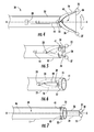
- a dissector 10 is provided in accordance with the present disclosure and includes a body 12, a first arm 14, a second arm 16, and a string 18.
- the first arm 14 extends from the body 12 to a distal end 15 and the second arm 16 extends from the body 12 to a distal end 17 in substantially the same direction as the first arm 14.
- the distal ends 15, 17 may be substantially the same distance from the body 12.
- the distal ends 15, 17 are blunt such that the distal ends 15, 17 may atraumatically dissect tissue.
- One end of the string 18 is coupled to the first arm 14 adjacent the distal end 15 and the other end of the string 18 is coupled to the second arm 16 adjacent the distal end 17.
- the distal end 15 of the first arm 14 is biased away from the distal end 17 of the second arm 17 such that the string 18 is taut.
- the body 12 of the dissector 10 may extend from a lumen of a tube 11.
- the dissector 10 has an expanded configuration ( FIG. 1 ) and a collapsed configuration ( FIG. 2 ).
- the first and second arms 14, 16 are positioned distally of a distal end of the tube 11 such that the string 18 is made taut by the distal ends 15, 17 being biased away from one another.
- the body 12 is retracted into tube 11 or the tube 11 is extended over the body 12 such that the tube 11 engages the first and second arms 14, 16 to urge the first and second arms 14, 16 and the distal ends 15, 17 towards one another and into the collapsed configuration.
- the distal ends 15, 17 protrude beyond the distal end of the tube 11 such that the distal ends 15, 17 may be used for blunt dissection of tissue.
- the string 18 is slack between the first and second arms 14, 16.
- the dissector 10 may include a transport configuration such that the distal ends 15, 17 are disposed within the tube 11.
- the string 18 may be disposed within the tube 11 or outside of the tube 11.
- the tube 11 may be a catheter tube positioned adjacent to tissue to be dissected and the dissector 10 is delivered through the catheter tube to the tissue to be dissected.
- the dissector 10 includes a vibration mechanism 20 configured to laterally vibrate the string 18.
- the vibration mechanism 20 may be operatively associated with one or more of the tube 11, the body 12, the first arm 14, and the second arm 16.
- the dissector 10 is inserted into a surgical site in the collapsed configuration.
- the surgical site may be an opening (e.g., natural orifice or incision) providing access to a body cavity of a patient.
- the dissector 10 may be inserted through a cannula or an access port (not shown).
- the body 12 or tube 11 of the dissector 10 are manipulated to dissect tissue with the distal ends 15, 17.
- the distal ends 15, 17 of the dissector 10 may not bluntly dissect tissue in contact therewith.
- the dissector 10 may be transitioned to the expanded configuration by extending the body 12 from the tube 11 or retracting the tube 11 from over the arms 14, 16.
- the string 18 may be used to dissect tissue.
- the tube 11 or the body 12 may be laterally vibrated to dissect tissue with the string 18.
- lateral vibration is oscillating movement of the string 18 in a direction transverse to a longitudinal axis A-A of the body 12 in a plane common with the distal ends 15, 17 as represented by the arrows T in FIG. 1 .
- the vibration mechanism 20 may be configured to vibrate at least one of the first and second arms 14, 16 to vibrate the string 18.
- another dissector 30 is provided in accordance with the present disclosure including a body 32, a pivot pin 33, a first arm 34, a second arm 36, and a string 38.
- the first arm 34 is a rigid member that extends from the body 32 to a distal end 35 and the second arm 36 is a rigid member that extends from the body 32 to a distal end 37 in substantially the same direction as the first arm 34.
- the distal ends 35, 37 may be substantially the same distance from the body 32.
- the distal ends 35, 37 are blunt such that the distal ends 35, 37 may atraumatically dissect tissue.
- One end of the string 38 is coupled to the first arm 34 adjacent the distal end 35 and the other end of the string 38 is coupled to the second arm 36 adjacent the distal end 37.
- the pivot pin 33 is adjacent a distal end of the body 32.
- a proximal end of the first arm 34 and a proximal end of the second arm 36 are coupled to the body 32 by the pivot pin 33.
- the dissector 30 has an expanded configuration ( FIG. 4 ) and a collapsed configuration ( FIG. 5 ).
- the distal ends 35, 37 of the first and second arms 34, 36, respectively are spaced-apart and the string 38 is taut between the first and second arms 34, 36.
- the distal ends 35, 37 of the first and second arms 34, 36, respectively are close to one another such that the string 38 is slack between the first and second arms 34, 36.
- the distal ends 35, 37 may be used for blunt dissection of tissue.
- the dissector 30 includes an actuation mechanism 40 configured to transition the dissector 30 between the expanded configuration and the collapsed configuration.
- the actuation mechanism 40 may include a biasing member 42 positioned about pivot pin 33 to bias the dissector 30 towards the expanded configuration.
- the biasing member 42 may be a torsion spring.
- the body 32 defines a lumen 41 and the pivot pin 33 is disposed within a slot 44 defined in sidewalls of the body 32 substantially parallel to a longitudinal axis A-A of the body 32.
- the actuation mechanism 40 includes a retractable member 46 coupled to the pivot pin 33.
- the retractable member 46 configured to translate the pivot pin 33 within the slot 44 along the longitudinal axis of the body 32 to transition the dissector 30 between the expanded configuration, the collapsed configuration, and the transport configuration.
- the retractable member 46 may be disposed within the lumen 41 of the body 30.
- the dissector 30 when the pivot pin 33 is positioned adjacent a distal end of the slot 44 the dissector 30is in the expanded configuration and when the pivot pin 33 is positioned adjacent a proximal end of the slot 44, the body 32 of the dissector 30 engages the arms 34, 36 to collapse the dissector 30 to the collapsed configuration.
- the distal ends 35, 37 When in the collapsed configuration, the distal ends 35, 37 may protrude from the distal end of the body 32.
- the retractable member 44 may translate the pivot pin 33 until the distal ends 35, 37 are drawn into the body 32 of the dissector 30 such that the dissector 30 is in a transport configuration as shown in FIG. 6 .
- the first and second arms 34, 36 being biased by the biasing member 42, may bias the dissector 30 to the expanded configuration.
- the actuation mechanism 40 includes a tube (not shown) substantially similar to the tube 11 of the dissector 10 detailed above, as such the tube and the use thereof will not be described in detail for reasons of brevity.
- the dissector 30 may be used substantially similar to the dissector 10 detailed above, as such the use of dissector 30 will not be detailed for reasons of brevity.
- the dissector 30 includes the vibration mechanism 20 configured to laterally vibrate the string 38.
- the vibration mechanism 20 may be operatively associated with one or more of the body 32, the first arm 34, and the second arm 36.
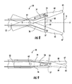
- yet another dissector 50 is provided in accordance with the present disclosure and includes a body 52, a first arm 54, a second arm 56, a string 58, a first jaw member 64, and a second jaw member 66.
- the first jaw member 64 extends from the body 52 to a distal end 65 and the second jaw member 66 extends from the body 52 to a distal end 67.
- the distal ends 65, 67 are blunt to atraumatically contact and dissect tissue in contact therewith.
- the first and second jaw members 64, 66 are coupled by a pivot pin or pivot 63 adjacent a distal end of the body 52.
- the first and second jaw members 64, 66 may be moveable relative to one another between an open condition ( FIG. 8 ) and a closed condition ( FIG. 9 ). In the open condition, the distal ends 65, 67 are spaced-apart a distance B as detailed below.
- the first arm 54 is at least partially disposed within the first jaw member 64 and the second arm 56 is at least partially disposed within the second jaw member 66. It is also within the scope of this disclosure that the first and second arms 54, 56 may be disposed on the outer surface of the first and second jaw members 64, 66 respectively. Proximal ends of each of the first and second arms 54, 56 extend proximally within the body 52. Alternatively, the proximal ends of each of the first and second arms 54, 56 may be fixed within and relative to a respective one of the first and second jaw members 64, 66 adjacent the distal end of the body 52.
- a distal end 55 of the first arm 54 is disposed within the first jaw member 64 and a distal end 57 of the second arm 56 is disposed within the second jaw member 66.
- the distal ends 55, 57 are substantially free to move transverse to a longitudinal axis A-A of the body and may be substantially free to move along the longitudinal axis A-A of a respective one of the jaw members 64, 66.
- the distal ends 55, 57 may be positioned about halfway along a length of a respective one of the first and second jaw members 64, 66 from the pivot 63 to a respective one of the distal ends 65, 67.
- the first and second arms 54, 56 are flexible such that each of the first and second arms 54, 56 functions as a leaf spring with the proximal ends thereof fixed and the distal ends 55, 57 thereof substantially free.
- the surfaces of the first and second jaw members 64, 66 opposing one another each define an opening 68.
- the string 58 passes through the openings 68 with one end of the string 58 coupled to the first arm 54 adjacent the distal end 55 and the other end of the string 58 coupled to the second arm 56 adjacent the distal end 57.
- the first and second jaw members 64, 66 are in the open condition as shown in FIG. 8
- the first and second arms 54, 56 are in an expanded configuration such that the string 58 is taut
- the first and second jaw members 64, 66 are in the closed condition as shown in FIG. 9
- the first and second arms 54, 56 are in a collapsed configuration such that the string 58 is slack.
- exemplary embodiments of vibration mechanisms 70, 80, 90 may be associated with the dissector 50 to induce oscillation (e.g., lateral, represented by arrows T, or longitudinal, represented by the arrows L, oscillation) of the string 58 when the string 58 is taut.
- the jaw members 64, 66 are substantially isolated from the vibration mechanism 70, 80, 90 such that the jaw members 64, 66 remain substantially stationary during the oscillation of the string 58.
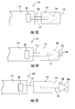
- a vibration mechanism 70 includes a magnetic coil 72 and a magnet 74.
- the magnet 74 is coupled to the first arm 54 adjacent the distal end 55.
- the magnet 74 is integrally formed with the first arm 54.
- the magnetic coil 72 is disposed within the first jaw member 64 adjacent the magnet 74.
- the magnetic coil 72 is in communication with an energy source 73 that induces a magnetic field about the magnetic coil 72.
- the magnetic field about the magnetic coil 72 alternates to attract and repel the magnet 74 to induce oscillation of the string 58 (e.g., lateral oscillation).
- the energy source 73 may be disposed within the dissector 50 or be external to the dissector 50.
- the vibration mechanism 70 may induce vibration in one of the first and second arms 54, 56 substantially similar to the resonant frequency of the one of the first and second arms 54, 56.
- a vibration mechanism 80 includes a rotary element 82 disposed on the first arm 54.
- the rotary element 82 may be positioned adjacent the distal end 55 of the first arm 54.
- the rotary element 82 includes an eccentric mass 84 configured to rotate about a center point 83 of the rotary element 82.
- the rotary element 82 may be a rotary motor.
- the rotation of the eccentric mass 84 about the center point 83 induces oscillation of the string 58. It will be appreciated that depending on the orientation of the rotary element 82, the oscillation of the string 58 may be lateral or longitudinal. For example, as shown in FIG.
- the eccentric mass 84 rotates substantially parallel to the longitudinal axis of the first arm 54 inducing lateral oscillation of the string 58 (i.e., oscillation transverse to the longitudinal axis as represented by arrows T in FIG. 11 ).
- the eccentric mass 84 may rotate orthogonal to the longitudinal axis of the first arm 54 inducing longitudinal oscillation of the string 58 (i.e., oscillation along the longitudinal axis as represented by arrows L in FIG. 11 ).
- the vibration mechanism 80 may induce vibration in one of the first and second arms 54, 56 substantially similar to the resonant frequency of the one of the first and second arms 54, 56.
- a vibration mechanism 90 includes one or more piezoelectric actuators 92, 94 associated with the first arm 54.
- the piezoelectric actuator 92 is a stripe actuator disposed on an outer surface of the first arm 54 such that when an electrical input is applied to the actuator 92, the actuator 92 deflects the first arm 54 to induce oscillation of the string 58. It will be appreciated that depending on the position of the actuator 92 along the first arm 54, the oscillation of the string 58 may be lateral or longitudinal. For example, as shown in FIG.
- the actuator 92 is positioned along a top surface of the first arm 54 to induce vibration in the first arm 54 towards and away from second arm 56 to induce lateral oscillation of the string 58 (i.e., oscillation transverse to the longitudinal axis as represented by arrows T in FIG. 12 ). Additionally or alternatively, the actuator 92 may be positioned along a side surface of the first arm 54 (i.e., rotated 90°) to induce longitudinal oscillation of the string 58 (i.e., oscillation along the longitudinal axis as represented by arrows L in FIG. 12 ).
- the piezoelectric actuator 94 is a stack actuator coupled to the first arm 54 adjacent the distal end 55 such that when an electrical input is applied to the actuator 94, the actuator 94 deflects the first arm 54 to induce oscillation of the string 58.
- the oscillation of the string 58 may be lateral or longitudinal.
- the actuator 94 is positioned substantially orthogonal to the longitudinal axis of the first jaw member 64 to induce lateral oscillation of the string 58 (i.e., oscillation transverse to the longitudinal axis as represented by arrows T in FIG. 12 ).
- the actuator 94 may be positioned substantially inline with the longitudinal axis of the first jaw member 64 to induce longitudinal oscillation of the string 58 (i.e., oscillation along the longitudinal axis as represented by arrows L in FIG. 12 ).
- the vibration mechanism 90 may induce vibration in one of the first and second arms 54, 56 substantially similar to the resonant frequency of the one of the first and second arms 54, 56. It is within the scope of this disclosure that a vibration mechanism 90 may include an actuator 92 and an actuator 94.
- each of the vibration mechanisms 70, 80, 90 are disposed within the first jaw member to act directly on the first arm 54; however, it is within the scope of this disclosure that any of the vibration mechanisms 70, 80, 90 may also be disposed within the second jaw member 66 to act directly on the second arm 56. In addition, it is contemplated that one or more of the vibration mechanisms 70, 80, 90 may be disposed within the first jaw member 64 or the second jaw member 66.
- the vibration mechanism vibrates the device in the sonic range (10-20K Hz).
- the dissector 50 is inserted into a surgical site with the jaw members 64, 66 in the closed condition.
- the distal ends 65, 67 of the jaw members 64, 66 may be used to dissect tissue. In some instances, the distal ends 65, 67 may not bluntly dissect tissue in contact therewith. In these instances, the jaw members 64, 66 may be transitioned to the open configuration. In the open configuration as shown in FIG. 8 , the first and second jaw members 64, 66 are spaced apart a distance B.
- the distance B may allow target tissue (i.e., tissue to be dissected) to pass between the first and second jaw members 64, 66 and prevent non-targeted tissue from passing between the first and second jaw members 64, 66.
- adhesions may be permitted to pass between the first and second jaw members 64, 66 and bowels may be prevented from passing between the first and second jaw members 64, 66.
- first and second jaw members 64, 66 When the first and second jaw members 64, 66 are in the open condition, the first and second jaw members 64, 66 are advanced to guide the targeted tissue towards the string 58. It will be appreciated that when the first and second jaw members 64, 66 are in the open condition, the dissector 50 is in the expanded configuration such that the string 58 is taut. The string 58 is then oscillated either manually or with one or more of the vibration mechanisms 70, 80, 90 detailed above to dissect the targeted tissue.
- still yet another dissector 110 is provided in accordance with the present disclosure and includes a body 112, a peanut 114, and a retractable knife 118.
- the peanut 114 is attached to a peanut shaft 113 that extends from a distal end of the body 112.
- the peanut 114 has a blunt distal end portion 115 for atraumatically dissecting tissue in contact therewith.
- the peanut 114 may be made of an absorbent material such that the peanut 114 may absorb fluids that result from the dissection of tissue (e.g., blood).
- the peanut shaft 113 may be operatively associated with the vibration mechanism 20 to induce lateral and/or longitudinal vibration of the peanut 114. The vibration of the peanut 114 may assist in the dissection of tissue in contact with the peanut 114.
- the retractable knife 118 has a retracted position ( FIG. 13 ), a first exposed position ( FIG. 14 ), and a second exposed position ( FIG. 15 ).
- the retractable knife 118 In the retracted position, the retractable knife 118 is disposed within the peanut 114 such that the sharp edges of the retractable knife 118 are prevented from contacting tissue.
- the retractable knife 118 In the first exposed position, the retractable knife 118 partially extends from the distal end portion 115 of the peanut 114 such that leading edges 118a of the retractable knife are at least partially exposed to cut tissue in contact therewith.
- the retractable knife 118 extends from the distal end portion 115 of the peanut 114. The leading edges 118a of the retractable knife 118 are sharpened to cut tissue in contact therewith.
- the retractable knife 118 may be coupled to the distal end of a knife shaft 117.
- the knife shaft 117 may extend from the proximal end of the retractable knife 118, through the peanut shaft 113, and into the body 112.
- the knife 118 may vibrate with the peanut 114 when in the retracted position or the exposed position.
- the dissector 110 is inserted into a surgical site with the retractable knife 118 in the retracted position. Similar to dissector 10 described above, the dissector 110 may be inserted through an access port (not shown).
- the body 112 When the distal end portion 115 of the peanut 114 is adjacent or in contact with tissue to be dissected, the body 112 is manipulated such that the distal end portion 115 atraumatically dissects tissue.
- the vibration mechanism 20 may be activated to induce vibration in the peanut 114. The vibration of the peanut 114 may assist the distal end portion 115 in atraumatically dissecting tissue.
- the retractable knife blade 118 may be exposed from within the peanut 114 such that the leading edges 118a sharply dissect the tissue. The retractable knife blade 118 may then be returned to the retracted position such that the peanut 114 may be used to bluntly dissect additional tissue.
Landscapes
- Health & Medical Sciences (AREA)
- Surgery (AREA)
- Life Sciences & Earth Sciences (AREA)
- Engineering & Computer Science (AREA)
- Molecular Biology (AREA)
- Biomedical Technology (AREA)
- Heart & Thoracic Surgery (AREA)
- Medical Informatics (AREA)
- Nuclear Medicine, Radiotherapy & Molecular Imaging (AREA)
- Animal Behavior & Ethology (AREA)
- General Health & Medical Sciences (AREA)
- Public Health (AREA)
- Veterinary Medicine (AREA)
- Dentistry (AREA)
- Mechanical Engineering (AREA)
- Surgical Instruments (AREA)
Applications Claiming Priority (2)
| Application Number | Priority Date | Filing Date | Title |
|---|---|---|---|
| US201461980637P | 2014-04-17 | 2014-04-17 | |
| US14/551,481 US9597105B2 (en) | 2014-04-17 | 2014-11-24 | Vibrating surgical instruments for blunt dissection |
Publications (2)
| Publication Number | Publication Date |
|---|---|
| EP2932924A1 true EP2932924A1 (de) | 2015-10-21 |
| EP2932924B1 EP2932924B1 (de) | 2020-03-18 |
Family
ID=52272900
Family Applications (1)
| Application Number | Title | Priority Date | Filing Date |
|---|---|---|---|
| EP14199666.0A Active EP2932924B1 (de) | 2014-04-17 | 2014-12-22 | Vibrierende chirurgische Instrumente zur stumpfen Dissektion |
Country Status (5)
| Country | Link |
|---|---|
| US (3) | US9597105B2 (de) |
| EP (1) | EP2932924B1 (de) |
| CN (1) | CN105030287B (de) |
| AU (1) | AU2014274552B2 (de) |
| CA (1) | CA2875152A1 (de) |
Families Citing this family (7)
| Publication number | Priority date | Publication date | Assignee | Title |
|---|---|---|---|---|
| US9597105B2 (en) | 2014-04-17 | 2017-03-21 | Covidien Lp | Vibrating surgical instruments for blunt dissection |
| CN107280728B (zh) * | 2017-08-04 | 2019-08-23 | 陆远 | 一种可防止血管内壁损伤的血栓清除器 |
| CN114945337A (zh) | 2019-11-06 | 2022-08-26 | 因赛特福仪器公司 | 用于切割组织的系统和方法 |
| USD974558S1 (en) | 2020-12-18 | 2023-01-03 | Stryker European Operations Limited | Ultrasonic knife |
| JP2024520392A (ja) | 2021-05-27 | 2024-05-24 | インサイトフル インストゥルメンツ, インコーポレイテッド | 組織を切開するためのシステムおよび方法 |
| EP4355087A4 (de) * | 2021-06-15 | 2024-12-04 | Soletech Limited | Veterinärmedizinische sägeanordnung |
| JP2024542474A (ja) * | 2021-11-30 | 2024-11-15 | インサイトフル インストゥルメンツ, インコーポレイテッド | 組織を切開するためのシステムおよび方法 |
Citations (5)
| Publication number | Priority date | Publication date | Assignee | Title |
|---|---|---|---|---|
| US6383194B1 (en) * | 2001-02-26 | 2002-05-07 | Viswanadham Pothula | Flexible ultrasonic surgical snare |
| EP1864622A2 (de) * | 2006-06-05 | 2007-12-12 | Naohisa Yahagi | Hochfrequenzbehandlungsinstrument |
| US20120296332A1 (en) * | 2011-05-16 | 2012-11-22 | Tyco Healthcare Group Lp | Thread-Like Knife for Tissue Cutting |
| US20130018402A1 (en) * | 2010-02-14 | 2013-01-17 | Polo Oscar R | Tissue severing devices and methods |
| US20130317515A1 (en) * | 2011-08-01 | 2013-11-28 | Olympus Medical Systems Corp. | Treatment instrument |
Family Cites Families (19)
| Publication number | Priority date | Publication date | Assignee | Title |
|---|---|---|---|---|
| US7534242B2 (en) | 2003-02-25 | 2009-05-19 | Artemis Medical, Inc. | Tissue separating catheter assembly and method |
| US7497866B2 (en) | 2000-07-18 | 2009-03-03 | Tissue Engineering Refraction Inc. | Methods for producing epithelial flaps on the cornea and for placement of ocular devices and lenses beneath an epithelial flap or membrane, epithelial delaminating devices, and structures of epithelium and ocular devices and lenses |
| US6863677B2 (en) | 2001-08-23 | 2005-03-08 | Eugene Michael Breznock | Method and apparatus for trephinating body vessels and hollow organ walls |
| US7481766B2 (en) * | 2003-08-14 | 2009-01-27 | Synthes (U.S.A.) | Multiple-blade retractor |
| US20050250984A1 (en) | 2004-05-07 | 2005-11-10 | Usgi Medical Inc. | Multiple removable apparatus and methods for manipulating and securing tissue |
| CN101039639A (zh) | 2004-06-16 | 2007-09-19 | 组织工程折射公司 | 上皮分层装置 |
| US20060064113A1 (en) * | 2004-09-17 | 2006-03-23 | Nakao Naomi L | Endoscopic mucosal resection method and associated instrument |
| US20060173481A1 (en) | 2005-02-03 | 2006-08-03 | Vascular Architects, Inc., A Delaware Corporation | Ring stripper with tissue dissecting element |
| EP1886634B1 (de) | 2005-05-31 | 2016-04-20 | Olympus Corporation | Gerät zur ablösung von schleimhaut |
| US7566340B2 (en) | 2006-12-04 | 2009-07-28 | Implicitcare, Llc | Surgical threading device and method for using same |
| CN101032417A (zh) * | 2007-03-30 | 2007-09-12 | 苏州华晟手术医疗器械有限公司 | 医用往复锯 |
| AU2008229774B2 (en) | 2007-10-05 | 2013-05-16 | Covidien Lp | Two-mode bladeless trocar assembly |
| US20100116287A1 (en) * | 2008-11-10 | 2010-05-13 | Yaneav Cohen | System and apparatus for dental hygiene |
| US20100198248A1 (en) | 2009-02-02 | 2010-08-05 | Ethicon Endo-Surgery, Inc. | Surgical dissector |
| EP2539009B1 (de) | 2010-02-26 | 2019-07-17 | The Board of Trustees of The Leland Stanford Junior University | Systeme zur endoluminalen herzklappenerzeugung |
| CN102335020B (zh) * | 2010-07-15 | 2014-01-01 | 北京蒙太因医疗器械有限公司 | 医用动力线锯 |
| US20120109184A1 (en) | 2010-11-01 | 2012-05-03 | Ethicon Endo-Surgery, Inc. | Vibratory motor use |
| CN203303117U (zh) * | 2013-04-22 | 2013-11-27 | 重庆西山科技有限公司 | 外科手术刨削器刀头 |
| US9597105B2 (en) | 2014-04-17 | 2017-03-21 | Covidien Lp | Vibrating surgical instruments for blunt dissection |
-
2014
- 2014-11-24 US US14/551,481 patent/US9597105B2/en not_active Expired - Fee Related
- 2014-12-10 AU AU2014274552A patent/AU2014274552B2/en not_active Ceased
- 2014-12-17 CA CA2875152A patent/CA2875152A1/en not_active Abandoned
- 2014-12-22 EP EP14199666.0A patent/EP2932924B1/de active Active
- 2014-12-30 CN CN201410841875.4A patent/CN105030287B/zh not_active Expired - Fee Related
-
2017
- 2017-03-07 US US15/451,511 patent/US10271867B2/en active Active
-
2019
- 2019-03-12 US US16/299,455 patent/US20190209200A1/en not_active Abandoned
Patent Citations (5)
| Publication number | Priority date | Publication date | Assignee | Title |
|---|---|---|---|---|
| US6383194B1 (en) * | 2001-02-26 | 2002-05-07 | Viswanadham Pothula | Flexible ultrasonic surgical snare |
| EP1864622A2 (de) * | 2006-06-05 | 2007-12-12 | Naohisa Yahagi | Hochfrequenzbehandlungsinstrument |
| US20130018402A1 (en) * | 2010-02-14 | 2013-01-17 | Polo Oscar R | Tissue severing devices and methods |
| US20120296332A1 (en) * | 2011-05-16 | 2012-11-22 | Tyco Healthcare Group Lp | Thread-Like Knife for Tissue Cutting |
| US20130317515A1 (en) * | 2011-08-01 | 2013-11-28 | Olympus Medical Systems Corp. | Treatment instrument |
Also Published As
| Publication number | Publication date |
|---|---|
| US20150297257A1 (en) | 2015-10-22 |
| US9597105B2 (en) | 2017-03-21 |
| CA2875152A1 (en) | 2015-10-17 |
| US20170172612A1 (en) | 2017-06-22 |
| US20190209200A1 (en) | 2019-07-11 |
| EP2932924B1 (de) | 2020-03-18 |
| AU2014274552A1 (en) | 2015-11-05 |
| AU2014274552B2 (en) | 2019-07-04 |
| CN105030287A (zh) | 2015-11-11 |
| CN105030287B (zh) | 2020-03-31 |
| US10271867B2 (en) | 2019-04-30 |
Similar Documents
| Publication | Publication Date | Title |
|---|---|---|
| US10271867B2 (en) | Vibrating surgical instruments for blunt dissection | |
| JP6960852B2 (ja) | 組織を切断する装置および方法 | |
| EP2967593B1 (de) | Chirurgischer ultraschallbohrer | |
| JP5648122B2 (ja) | 切断性が改善され、軟性組織及び薄い骨の詰まりが軽減される回転切断処置具 | |
| ES2702673T3 (es) | Conjunto de instrumento ultrasónico | |
| EP2826428A1 (de) | Laparoskopisches Linsenwischmerkmal auf der Welle einer chirurgischen Vorrichtung oder Klemmbackenelement | |
| US20150066033A1 (en) | Method and apparatus for performing minimally invasive arthroscopic procedures | |
| US20140148729A1 (en) | Micro-mechanical devices and methods for brain tumor removal | |
| EP1972288A1 (de) | Rasierklinge mit Tiefenmarkierungen | |
| JP2001513355A (ja) | 廃棄可能な腹腔鏡式細切装置 | |
| BR112016011159B1 (pt) | Aparelho | |
| BR112012020166B1 (pt) | instrumento cirúrgico | |
| WO2010027888A1 (en) | Ultrasonic surgical blade | |
| JPH02164360A (ja) | 眼の手術用具 | |
| US20180289436A1 (en) | Method and apparatus for performing minimally invasive arthroscopic procedures | |
| ES2682753T3 (es) | Aparatos para cortar un puente tisular y/o retirar una pinza o una sutura de una válvula cardiaca | |
| EP3182911A1 (de) | Probenauffindungssysteme | |
| US9603616B2 (en) | Vibrating surgical instruments for blunt dissection and methods for use thereof | |
| US20120130392A1 (en) | Necrosectomy assist device | |
| KR102720891B1 (ko) | 내장형 진동 박리기를 구비한 내시경 절제술용 캡 | |
| EP3100689B1 (de) | Chirurgische instrumente zur stumpfen und scharfen gewebepräparation | |
| US20090182367A1 (en) | Adjustable Width Trocar | |
| BR202023010509U2 (pt) | Disposição construtiva aplicada em cânulas de microdebridação descartável e dispositivo de dobra | |
| BR102023014592A2 (pt) | Dispositivo e bolsa para morcelamento e/ou coleta de tecidos/órgãos minimamente invasiva | |
| WO2016171125A1 (ja) | 組織切除システム |
Legal Events
| Date | Code | Title | Description |
|---|---|---|---|
| PUAI | Public reference made under article 153(3) epc to a published international application that has entered the european phase |
Free format text: ORIGINAL CODE: 0009012 |
|
| AK | Designated contracting states |
Kind code of ref document: A1 Designated state(s): AL AT BE BG CH CY CZ DE DK EE ES FI FR GB GR HR HU IE IS IT LI LT LU LV MC MK MT NL NO PL PT RO RS SE SI SK SM TR |
|
| AX | Request for extension of the european patent |
Extension state: BA ME |
|
| 17P | Request for examination filed |
Effective date: 20160419 |
|
| RBV | Designated contracting states (corrected) |
Designated state(s): AL AT BE BG CH CY CZ DE DK EE ES FI FR GB GR HR HU IE IS IT LI LT LU LV MC MK MT NL NO PL PT RO RS SE SI SK SM TR |
|
| GRAP | Despatch of communication of intention to grant a patent |
Free format text: ORIGINAL CODE: EPIDOSNIGR1 |
|
| STAA | Information on the status of an ep patent application or granted ep patent |
Free format text: STATUS: GRANT OF PATENT IS INTENDED |
|
| RIC1 | Information provided on ipc code assigned before grant |
Ipc: A61B 17/3205 20060101AFI20190905BHEP Ipc: A61B 17/32 20060101ALN20190905BHEP |
|
| RIC1 | Information provided on ipc code assigned before grant |
Ipc: A61B 17/32 20060101ALN20190911BHEP Ipc: A61B 17/3205 20060101AFI20190911BHEP |
|
| INTG | Intention to grant announced |
Effective date: 20191007 |
|
| RIN1 | Information on inventor provided before grant (corrected) |
Inventor name: BANERJEE, SAUMYA Inventor name: GALER, KATELYN Inventor name: WILLIAMS, JUSTIN Inventor name: RACENET, DANYEL Inventor name: SNIFFIN, KEVIN Inventor name: MARCZYK, STANISLAW |
|
| GRAS | Grant fee paid |
Free format text: ORIGINAL CODE: EPIDOSNIGR3 |
|
| GRAA | (expected) grant |
Free format text: ORIGINAL CODE: 0009210 |
|
| STAA | Information on the status of an ep patent application or granted ep patent |
Free format text: STATUS: THE PATENT HAS BEEN GRANTED |
|
| AK | Designated contracting states |
Kind code of ref document: B1 Designated state(s): AL AT BE BG CH CY CZ DE DK EE ES FI FR GB GR HR HU IE IS IT LI LT LU LV MC MK MT NL NO PL PT RO RS SE SI SK SM TR |
|
| REG | Reference to a national code |
Ref country code: GB Ref legal event code: FG4D |
|
| REG | Reference to a national code |
Ref country code: DE Ref legal event code: R096 Ref document number: 602014062454 Country of ref document: DE |
|
| REG | Reference to a national code |
Ref country code: AT Ref legal event code: REF Ref document number: 1245002 Country of ref document: AT Kind code of ref document: T Effective date: 20200415 Ref country code: IE Ref legal event code: FG4D |
|
| PG25 | Lapsed in a contracting state [announced via postgrant information from national office to epo] |
Ref country code: RS Free format text: LAPSE BECAUSE OF FAILURE TO SUBMIT A TRANSLATION OF THE DESCRIPTION OR TO PAY THE FEE WITHIN THE PRESCRIBED TIME-LIMIT Effective date: 20200318 Ref country code: FI Free format text: LAPSE BECAUSE OF FAILURE TO SUBMIT A TRANSLATION OF THE DESCRIPTION OR TO PAY THE FEE WITHIN THE PRESCRIBED TIME-LIMIT Effective date: 20200318 Ref country code: NO Free format text: LAPSE BECAUSE OF FAILURE TO SUBMIT A TRANSLATION OF THE DESCRIPTION OR TO PAY THE FEE WITHIN THE PRESCRIBED TIME-LIMIT Effective date: 20200618 |
|
| REG | Reference to a national code |
Ref country code: NL Ref legal event code: MP Effective date: 20200318 |
|
| PG25 | Lapsed in a contracting state [announced via postgrant information from national office to epo] |
Ref country code: GR Free format text: LAPSE BECAUSE OF FAILURE TO SUBMIT A TRANSLATION OF THE DESCRIPTION OR TO PAY THE FEE WITHIN THE PRESCRIBED TIME-LIMIT Effective date: 20200619 Ref country code: BG Free format text: LAPSE BECAUSE OF FAILURE TO SUBMIT A TRANSLATION OF THE DESCRIPTION OR TO PAY THE FEE WITHIN THE PRESCRIBED TIME-LIMIT Effective date: 20200618 Ref country code: LV Free format text: LAPSE BECAUSE OF FAILURE TO SUBMIT A TRANSLATION OF THE DESCRIPTION OR TO PAY THE FEE WITHIN THE PRESCRIBED TIME-LIMIT Effective date: 20200318 Ref country code: SE Free format text: LAPSE BECAUSE OF FAILURE TO SUBMIT A TRANSLATION OF THE DESCRIPTION OR TO PAY THE FEE WITHIN THE PRESCRIBED TIME-LIMIT Effective date: 20200318 Ref country code: HR Free format text: LAPSE BECAUSE OF FAILURE TO SUBMIT A TRANSLATION OF THE DESCRIPTION OR TO PAY THE FEE WITHIN THE PRESCRIBED TIME-LIMIT Effective date: 20200318 |
|
| REG | Reference to a national code |
Ref country code: LT Ref legal event code: MG4D |
|
| PG25 | Lapsed in a contracting state [announced via postgrant information from national office to epo] |
Ref country code: NL Free format text: LAPSE BECAUSE OF FAILURE TO SUBMIT A TRANSLATION OF THE DESCRIPTION OR TO PAY THE FEE WITHIN THE PRESCRIBED TIME-LIMIT Effective date: 20200318 |
|
| PG25 | Lapsed in a contracting state [announced via postgrant information from national office to epo] |
Ref country code: SM Free format text: LAPSE BECAUSE OF FAILURE TO SUBMIT A TRANSLATION OF THE DESCRIPTION OR TO PAY THE FEE WITHIN THE PRESCRIBED TIME-LIMIT Effective date: 20200318 Ref country code: EE Free format text: LAPSE BECAUSE OF FAILURE TO SUBMIT A TRANSLATION OF THE DESCRIPTION OR TO PAY THE FEE WITHIN THE PRESCRIBED TIME-LIMIT Effective date: 20200318 Ref country code: PT Free format text: LAPSE BECAUSE OF FAILURE TO SUBMIT A TRANSLATION OF THE DESCRIPTION OR TO PAY THE FEE WITHIN THE PRESCRIBED TIME-LIMIT Effective date: 20200812 Ref country code: SK Free format text: LAPSE BECAUSE OF FAILURE TO SUBMIT A TRANSLATION OF THE DESCRIPTION OR TO PAY THE FEE WITHIN THE PRESCRIBED TIME-LIMIT Effective date: 20200318 Ref country code: IS Free format text: LAPSE BECAUSE OF FAILURE TO SUBMIT A TRANSLATION OF THE DESCRIPTION OR TO PAY THE FEE WITHIN THE PRESCRIBED TIME-LIMIT Effective date: 20200718 Ref country code: CZ Free format text: LAPSE BECAUSE OF FAILURE TO SUBMIT A TRANSLATION OF THE DESCRIPTION OR TO PAY THE FEE WITHIN THE PRESCRIBED TIME-LIMIT Effective date: 20200318 Ref country code: RO Free format text: LAPSE BECAUSE OF FAILURE TO SUBMIT A TRANSLATION OF THE DESCRIPTION OR TO PAY THE FEE WITHIN THE PRESCRIBED TIME-LIMIT Effective date: 20200318 Ref country code: LT Free format text: LAPSE BECAUSE OF FAILURE TO SUBMIT A TRANSLATION OF THE DESCRIPTION OR TO PAY THE FEE WITHIN THE PRESCRIBED TIME-LIMIT Effective date: 20200318 |
|
| REG | Reference to a national code |
Ref country code: AT Ref legal event code: MK05 Ref document number: 1245002 Country of ref document: AT Kind code of ref document: T Effective date: 20200318 |
|
| REG | Reference to a national code |
Ref country code: DE Ref legal event code: R097 Ref document number: 602014062454 Country of ref document: DE |
|
| PLBE | No opposition filed within time limit |
Free format text: ORIGINAL CODE: 0009261 |
|
| STAA | Information on the status of an ep patent application or granted ep patent |
Free format text: STATUS: NO OPPOSITION FILED WITHIN TIME LIMIT |
|
| PG25 | Lapsed in a contracting state [announced via postgrant information from national office to epo] |
Ref country code: ES Free format text: LAPSE BECAUSE OF FAILURE TO SUBMIT A TRANSLATION OF THE DESCRIPTION OR TO PAY THE FEE WITHIN THE PRESCRIBED TIME-LIMIT Effective date: 20200318 Ref country code: IT Free format text: LAPSE BECAUSE OF FAILURE TO SUBMIT A TRANSLATION OF THE DESCRIPTION OR TO PAY THE FEE WITHIN THE PRESCRIBED TIME-LIMIT Effective date: 20200318 Ref country code: AT Free format text: LAPSE BECAUSE OF FAILURE TO SUBMIT A TRANSLATION OF THE DESCRIPTION OR TO PAY THE FEE WITHIN THE PRESCRIBED TIME-LIMIT Effective date: 20200318 Ref country code: DK Free format text: LAPSE BECAUSE OF FAILURE TO SUBMIT A TRANSLATION OF THE DESCRIPTION OR TO PAY THE FEE WITHIN THE PRESCRIBED TIME-LIMIT Effective date: 20200318 |
|
| PGFP | Annual fee paid to national office [announced via postgrant information from national office to epo] |
Ref country code: GB Payment date: 20201123 Year of fee payment: 7 Ref country code: DE Payment date: 20201119 Year of fee payment: 7 Ref country code: FR Payment date: 20201120 Year of fee payment: 7 |
|
| 26N | No opposition filed |
Effective date: 20201221 |
|
| PG25 | Lapsed in a contracting state [announced via postgrant information from national office to epo] |
Ref country code: PL Free format text: LAPSE BECAUSE OF FAILURE TO SUBMIT A TRANSLATION OF THE DESCRIPTION OR TO PAY THE FEE WITHIN THE PRESCRIBED TIME-LIMIT Effective date: 20200318 |
|
| PG25 | Lapsed in a contracting state [announced via postgrant information from national office to epo] |
Ref country code: SI Free format text: LAPSE BECAUSE OF FAILURE TO SUBMIT A TRANSLATION OF THE DESCRIPTION OR TO PAY THE FEE WITHIN THE PRESCRIBED TIME-LIMIT Effective date: 20200318 |
|
| REG | Reference to a national code |
Ref country code: CH Ref legal event code: PL |
|
| PG25 | Lapsed in a contracting state [announced via postgrant information from national office to epo] |
Ref country code: MC Free format text: LAPSE BECAUSE OF FAILURE TO SUBMIT A TRANSLATION OF THE DESCRIPTION OR TO PAY THE FEE WITHIN THE PRESCRIBED TIME-LIMIT Effective date: 20200318 |
|
| REG | Reference to a national code |
Ref country code: BE Ref legal event code: MM Effective date: 20201231 |
|
| PG25 | Lapsed in a contracting state [announced via postgrant information from national office to epo] |
Ref country code: IE Free format text: LAPSE BECAUSE OF NON-PAYMENT OF DUE FEES Effective date: 20201222 Ref country code: LU Free format text: LAPSE BECAUSE OF NON-PAYMENT OF DUE FEES Effective date: 20201222 |
|
| PG25 | Lapsed in a contracting state [announced via postgrant information from national office to epo] |
Ref country code: LI Free format text: LAPSE BECAUSE OF NON-PAYMENT OF DUE FEES Effective date: 20201231 Ref country code: CH Free format text: LAPSE BECAUSE OF NON-PAYMENT OF DUE FEES Effective date: 20201231 |
|
| PG25 | Lapsed in a contracting state [announced via postgrant information from national office to epo] |
Ref country code: TR Free format text: LAPSE BECAUSE OF FAILURE TO SUBMIT A TRANSLATION OF THE DESCRIPTION OR TO PAY THE FEE WITHIN THE PRESCRIBED TIME-LIMIT Effective date: 20200318 Ref country code: MT Free format text: LAPSE BECAUSE OF FAILURE TO SUBMIT A TRANSLATION OF THE DESCRIPTION OR TO PAY THE FEE WITHIN THE PRESCRIBED TIME-LIMIT Effective date: 20200318 Ref country code: CY Free format text: LAPSE BECAUSE OF FAILURE TO SUBMIT A TRANSLATION OF THE DESCRIPTION OR TO PAY THE FEE WITHIN THE PRESCRIBED TIME-LIMIT Effective date: 20200318 |
|
| PG25 | Lapsed in a contracting state [announced via postgrant information from national office to epo] |
Ref country code: MK Free format text: LAPSE BECAUSE OF FAILURE TO SUBMIT A TRANSLATION OF THE DESCRIPTION OR TO PAY THE FEE WITHIN THE PRESCRIBED TIME-LIMIT Effective date: 20200318 Ref country code: AL Free format text: LAPSE BECAUSE OF FAILURE TO SUBMIT A TRANSLATION OF THE DESCRIPTION OR TO PAY THE FEE WITHIN THE PRESCRIBED TIME-LIMIT Effective date: 20200318 |
|
| REG | Reference to a national code |
Ref country code: DE Ref legal event code: R119 Ref document number: 602014062454 Country of ref document: DE |
|
| PG25 | Lapsed in a contracting state [announced via postgrant information from national office to epo] |
Ref country code: BE Free format text: LAPSE BECAUSE OF NON-PAYMENT OF DUE FEES Effective date: 20201231 |
|
| GBPC | Gb: european patent ceased through non-payment of renewal fee |
Effective date: 20211222 |
|
| PG25 | Lapsed in a contracting state [announced via postgrant information from national office to epo] |
Ref country code: GB Free format text: LAPSE BECAUSE OF NON-PAYMENT OF DUE FEES Effective date: 20211222 Ref country code: DE Free format text: LAPSE BECAUSE OF NON-PAYMENT OF DUE FEES Effective date: 20220701 |
|
| PG25 | Lapsed in a contracting state [announced via postgrant information from national office to epo] |
Ref country code: FR Free format text: LAPSE BECAUSE OF NON-PAYMENT OF DUE FEES Effective date: 20211231 |