EP2932498B1 - Anordnung zum betreiben von lichtquellen - Google Patents
Anordnung zum betreiben von lichtquellen Download PDFInfo
- Publication number
- EP2932498B1 EP2932498B1 EP13810925.1A EP13810925A EP2932498B1 EP 2932498 B1 EP2932498 B1 EP 2932498B1 EP 13810925 A EP13810925 A EP 13810925A EP 2932498 B1 EP2932498 B1 EP 2932498B1
- Authority
- EP
- European Patent Office
- Prior art keywords
- light sources
- current
- supply voltage
- output circuit
- arrangement according
- Prior art date
- Legal status (The legal status is an assumption and is not a legal conclusion. Google has not performed a legal analysis and makes no representation as to the accuracy of the status listed.)
- Active
Links
Images

Classifications
-
- G—PHYSICS
- G08—SIGNALLING
- G08B—SIGNALLING SYSTEMS, e.g. PERSONAL CALLING SYSTEMS; ORDER TELEGRAPHS; ALARM SYSTEMS
- G08B7/00—Signalling systems according to two or more of groups G08B3/00 - G08B6/00
- G08B7/06—Signalling systems according to two or more of groups G08B3/00 - G08B6/00 using electric transmission, e.g. involving audible and visible signalling through the use of sound and light sources
- G08B7/062—Signalling systems according to two or more of groups G08B3/00 - G08B6/00 using electric transmission, e.g. involving audible and visible signalling through the use of sound and light sources indicating emergency exits
-
- H—ELECTRICITY
- H02—GENERATION; CONVERSION OR DISTRIBUTION OF ELECTRIC POWER
- H02J—ELECTRIC POWER NETWORKS; CIRCUIT ARRANGEMENTS OR SYSTEMS FOR SUPPLYING OR DISTRIBUTING ELECTRIC POWER; SYSTEMS FOR STORING ELECTRIC ENERGY
- H02J9/00—Circuit arrangements for emergency or stand-by power supply, e.g. for emergency lighting
- H02J9/04—Circuit arrangements for emergency or stand-by power supply, e.g. for emergency lighting in which the distribution system is disconnected from the normal source and connected to a standby source
- H02J9/06—Circuit arrangements for emergency or stand-by power supply, e.g. for emergency lighting in which the distribution system is disconnected from the normal source and connected to a standby source with automatic change-over, e.g. UPS systems
- H02J9/062—Circuit arrangements for emergency or stand-by power supply, e.g. for emergency lighting in which the distribution system is disconnected from the normal source and connected to a standby source with automatic change-over, e.g. UPS systems for AC powered loads
- H02J9/065—Circuit arrangements for emergency or stand-by power supply, e.g. for emergency lighting in which the distribution system is disconnected from the normal source and connected to a standby source with automatic change-over, e.g. UPS systems for AC powered loads for lighting purposes
-
- H—ELECTRICITY
- H05—ELECTRIC TECHNIQUES NOT OTHERWISE PROVIDED FOR
- H05B—ELECTRIC HEATING; ELECTRIC LIGHT SOURCES NOT OTHERWISE PROVIDED FOR; CIRCUIT ARRANGEMENTS FOR ELECTRIC LIGHT SOURCES, IN GENERAL
- H05B45/00—Circuit arrangements for operating light-emitting diodes [LED]
- H05B45/30—Driver circuits
- H05B45/395—Linear regulators
-
- G—PHYSICS
- G09—EDUCATION; CRYPTOGRAPHY; DISPLAY; ADVERTISING; SEALS
- G09F—DISPLAYING; ADVERTISING; SIGNS; LABELS OR NAME-PLATES; SEALS
- G09F13/00—Illuminated signs; Luminous advertising
- G09F13/04—Signs, boards or panels, illuminated from behind the insignia
- G09F13/0418—Constructional details
- G09F2013/05—Constructional details indicating exit way or orientation
-
- Y—GENERAL TAGGING OF NEW TECHNOLOGICAL DEVELOPMENTS; GENERAL TAGGING OF CROSS-SECTIONAL TECHNOLOGIES SPANNING OVER SEVERAL SECTIONS OF THE IPC; TECHNICAL SUBJECTS COVERED BY FORMER USPC CROSS-REFERENCE ART COLLECTIONS [XRACs] AND DIGESTS
- Y02—TECHNOLOGIES OR APPLICATIONS FOR MITIGATION OR ADAPTATION AGAINST CLIMATE CHANGE
- Y02B—CLIMATE CHANGE MITIGATION TECHNOLOGIES RELATED TO BUILDINGS, e.g. HOUSING, HOUSE APPLIANCES OR RELATED END-USER APPLICATIONS
- Y02B20/00—Energy efficient lighting technologies, e.g. halogen lamps or gas discharge lamps
- Y02B20/30—Semiconductor lamps, e.g. solid state lamps [SSL] light emitting diodes [LED] or organic LED [OLED]
Definitions
- the present invention relates to an arrangement for operating light sources, which has an operating device for supplying power to the light sources and an output circuit containing the light sources and connected to the operating device via two lines.
- the present invention relates to emergency lights, with the aid of which escape routes are to be displayed and also to be specifically illuminated in certain situations.
- Emergency lights are primarily used to indicate an escape route using an illuminated pictogram.
- emergency lights of this type are installed above the exits of rooms in order to indicate to people in an emergency how they can leave the room or the building directly.
- emergency lights are permanently active and are often secured by means of additional measures against failures of the general power supply, so that they can continue to illuminate the pictogram at any time, in particular even if the general power supply fails.
- emergency lights which additionally also emit light in such a way that, for example, an escape route located below the emergency light in the event of an emergency in which e.g. the general room lighting fails, is illuminated.
- escape route illumination is realized, for example, by arranging an additional light source with an associated light emitting element on the underside of the pictogram housing, via which the light is emitted into the desired area.
- this escape route illumination is only activated in the event of an actual emergency.
- the integration of such intelligence in a corresponding emergency light is usually not a problem if it is a so-called surface-mounted or recessed light.
- the pictogram is usually coupled directly to the housing for the operating device for the power supply of the light sources, so that the light sources can be operated in the desired operating mode without great effort by using appropriate lines.
- emergency luminaires in the form of so-called suspended luminaires are often used, in which the luminaire is only suspended using two steel cables. Strictly speaking, the housing with the operating device for power supply to the light sources is attached to the ceiling of a room or another support element, whereas the pictogram with the light sources is separated from the housing for the operating device and is only connected to it via two steel cables.
- the steel cables are used not only to hang the pictogram but also to supply power to the output circuit on the pictogram with the light sources.
- the problem then arises that, due to the fact that only two lines for the power supply are available for the light sources, it is difficult to implement a situation-dependent control of the light sources in the output circuit. With the only two lines available, signal transmission is difficult or can only be implemented with great effort, and further control lines are not available.
- an additional escape route illumination or a situation-dependent operation of the light sources for the pictogram lighting was therefore not planned.
- US 2010/0275478 A1 discloses a combination of exit sign and emergency light to direct attention to exits in a building.
- the object of the present invention is to avoid the above-mentioned problems and to open up the possibility, even with suspended emergency lights, of optionally activating an escape route illumination and / or of controlling the light sources provided for illuminating the pictogram depending on the situation.
- the solution proposed according to the invention is based on the fundamental idea of controlling the light sources in the output circuit by reversing the polarity of the supply voltage made available by the operating device via the two lines.
- the operating device provides an essentially constant supply voltage, the polarity of which can be changed, however, depending on the manner in which the light sources in the output circuit are to be operated.
- the output circuit is designed such that a first part of the light sources is supplied with current at both polarities of the supply voltage, whereas a second part of the light sources is supplied with current only at one of the two polarities. If the arrangement according to the invention is used in an emergency luminaire with an ERI, this means that the light sources for the pictogram illumination represent the first part of the light sources that are supplied with current in both polarities, while the light sources for the ERI represent the second Represent part of the light sources.
- an arrangement for operating light sources with an operating device for supplying power to the light sources and an output circuit containing the light sources and connected to the operating device via two lines is accordingly proposed, the operating device being designed to provide a substantially constant supply voltage to provide, the polarity of which can be changed, and the output circuit being designed such that a first part of the light sources is supplied with current in both polarities of the supply voltage and a second part of the light sources is supplied with current only in one of the two polarities of the supply voltage becomes.
- a second idea according to the invention is based in turn on the concept that the operating device provides an essentially constant supply voltage, the polarity of which can be changed.
- the output circuit with the light sources has means for setting an essentially constant current, the magnitude of which depends on the polarity of the supply voltage.
- an arrangement for operating light sources with an operating device for supplying power to the light sources and an output circuit containing the light sources and connected to the operating device via two lines is proposed, the operating device being designed to supply a substantially constant supply voltage for To provide, whose polarity is variable, and wherein the output circuit has means for setting a substantially constant current, the level of which is dependent on the polarity of the supply voltage.
- the light sources in the output circuit are preferably LEDs.
- a rectifier is provided in the output circuit.
- the adjustment of the level of the substantially constant current depending on the polarity of the supply voltage can then take place, for example, with the aid of a constant current regulator implemented by a transistor, which is arranged in the LED branch.
- This transistor can then be controlled in a corresponding manner via a diode with evaluation circuit connected to the supply lines in order to set a different current level.
- the operation of further LEDs depending on the polarity of the supply voltage - for example for an ERI - can be implemented, for example, by providing a second branch in parallel with the branch with the first LEDs and the associated rectifier, which branch contains the second group of LEDs.
- the rectifying effect of the LEDs or an additional diode arranged in this branch ensures that these light sources are activated only at one of the two polarities of the supply voltage.
- a controller for setting the current at a certain level can be provided, which is then preferably implemented in the form of a so-called switching controller for reasons of efficiency.
- the solution according to the invention thus creates a simple and elegant possibility of carrying out a situation-dependent control of the light sources located in the output area despite the connection between the supply device and the output circuit via only two lines. Suspended emergency lights can now be realized in a simple manner, which nevertheless contain an escape route illumination.
- FIG. 1 shows first the side view of a so-called. Suspended emergency light 1 which represents a preferred application example of the present invention.
- the luminaire 1 is fastened to a support (not shown), for example on the ceiling of a room, with only a narrow, rectangular housing 5 being fastened to the ceiling, in which an operating device 6 for operating the light sources of the luminaire 1 is arranged is.
- the operating device 6, which is connected to the lines for the general power supply, serves to convert the supply voltage made available by the network into a suitable current or a suitable voltage for operating the light sources.
- the light sources themselves are arranged in a second module 10, which is suspended or suspended from the housing 5.
- This second module 10 is suspended here via two cables 7 and 8, which consist of an electrically conductive material and additionally also serve to transmit the supply voltage provided by the operating device 6. There are no further connections between the operating device 6 and the module 10, in particular no additional lines are provided for data transmission or the like.
- the module 10 suspended over the ropes or lines 7 and 8 is primarily used to display an escape route and has one or two for this purpose in a known manner translucent panes arranged opposite one another, which are provided with a pictogram 11.
- the pictogram shows the direction of an escape route and is backlit by means of light sources located in the module 10, the pictogram 11 generally being intended to be permanently illuminated.
- the lamp 1 from Figure 1 a so-called emergency route illumination (ERI) is provided, which is implemented by two light sources 12 arranged on the underside of the module 10 and, if appropriate, associated optical elements. Light is emitted in a targeted manner into an area below the luminaire 1 via these light sources 12 and any additional optics present in order to illuminate the escape route underneath.
- ERP emergency route illumination
- the pictogram 11 is to be illuminated permanently, that is also in the event that there is no emergency, the escape route should only be illuminated via the additional light sources 12 if there is actually an emergency.
- a simple and elegant possibility is created, despite the connection between the operating device 6 and the module 10, of being able to carry out a situation-dependent control of the different light sources of the module 10 only via the lines 7 and 8.
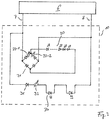
- Figure 2 shows a first variant of an arrangement according to the invention for operating the light sources of the luminaire, it being assumed that both the pictogram lighting and the ERI are carried out with the aid of LEDs.
- the output circuit of the circuit arrangement which is coupled to the operating device 6 via the two lines 7 and 8 and which is implemented in the pictogram module 10, there are on the one hand first LEDs 20 which are provided for pictogram lighting and at least one second LED 30, with the help of which the Emergency Route Illumination is implemented.
- the invention provides in a first step that, in contrast to previous solutions in which the control gear is used 6 a constant current has been made available via the connecting lines 7 and 8, an essentially constant voltage is now supplied to the output circuit.
- the polarity of the voltage can, however, be set by the operating device 6 depending on the situation, so that either a positive or a negative voltage is present on line 7.
- the second branch with the at least one second LED 30, however, has no such rectifier, so that due to the rectifying effect of the LED 30 or an additional diode 31 arranged in the branch, current only flows when a positive voltage is present on the line 7. If, on the other hand, the polarity of the supply voltage is reversed, no current can flow through the branch with the second LED 30 and this emits no light. Ultimately, this means that the supply device 6 can be set by appropriately selecting the polarity of the supply voltage, whether both LED groups 20, 30 are active or only the LEDs 20 for pictogram lighting.
- the LEDs 20, 30 are particularly efficient when they are operated continuously with a constant current. Accordingly, both the branch with the first LEDs 20 and the branch with the at least one second LED 30 have, in series with the respective LEDs 20 and 30, a current regulator 22 and 32, respectively, which essentially the one provided by the operating device 6 converts constant supply voltage into a constant current.
- the first current regulator 22 is preferably designed as a transistor, while the second current regulator 32 is implemented in the form of a switching regulator for reasons of efficiency.
- the design of the current regulator 22 for the first LED group 20 as a controllable transistor also has the advantage that the brightness of the first LED group 20 can be changed in a relatively simple manner in accordance with an advantageous development of the basic principle of the invention just described.
- a control of the transistor 22 can be carried out via a control branch which runs parallel to the rectifier and which contains a diode 23 and a resistor 24.
- the polarity of the supply voltage can be assessed here with the aid of the diode 23, that is to say the transistor 22 is activated as a function of the polarity of the supply voltage.
- FIG. 3 An alternative embodiment to the circuit arrangement according to Figure 2 is in Figure 3 shown, this variant differing primarily with regard to the question of the setting of the brightness of the first LED group 20 depending on the polarity of the supply voltage.
- There is now no separate branch for controlling a current regulator as is the case in the variant according to Figure 2 was the case.
- two current regulators 22-1 and 22-2 are now provided in the two branches of the bridge rectifier 21. Depending on the polarity of the supply voltage, current flows through only one of these two branches and accordingly only the corresponding current regulator 22-1 or 22-2 is active. Both current regulators 22-1, 22-2 therefore only have to be designed in such a way that they set the current to a suitable level in the event that current flows through them.
- the arrangement according to the invention thus provides the possibility, in spite of connection via only two lines, between an operating device and an output circuit with a plurality of light sources to control the light sources without the need to transmit additional control signals depending on the situation.
- this opens up the possibility of implementing an emergency route illumination even with suspended emergency lights and / or adjusting the brightness of the pictogram lighting.
Landscapes
- Business, Economics & Management (AREA)
- Emergency Management (AREA)
- Physics & Mathematics (AREA)
- General Physics & Mathematics (AREA)
- Engineering & Computer Science (AREA)
- Power Engineering (AREA)
- Circuit Arrangement For Electric Light Sources In General (AREA)
- Non-Portable Lighting Devices Or Systems Thereof (AREA)
Description
- Die vorliegende Erfindung betrifft eine Anordnung zum Betreiben von Lichtquellen, welche ein Betriebsgerät zur Stromversorgung der Lichtquellen sowie einen die Lichtquellen beinhaltenden und mit dem Betriebsgerät über zwei Leitungen verbundenen Ausgangskreis aufweist. Insbesondere betrifft die vorliegende Erfindung Notleuchten, mit deren Hilfe Rettungswege angezeigt und in bestimmten Situationen auch gezielt beleuchtet werden sollen.
- Notleuchten dienen in erster Linie dazu, mit Hilfe eines beleuchteten Piktogramms einen Fluchtweg anzuzeigen. Bspw. werden derartige Notleuchten oberhalb der Ausgänge von Räumen montiert, um im Falle eines Notfalls Personen anzuzeigen, auf welchem Wege sie den Raum bzw. das Gebäude unmittelbar verlassen können. Üblicherweise sind derartige Notleuchten dauerhaft aktiv und oftmals mittels zusätzlicher Maßnahmen auch gegen Ausfälle der allgemeinen Stromversorgung abgesichert, so dass sie jederzeit, insbesondere auch bei einem Ausfall der allgemeinen Stromversorgung weiterhin das Piktogramm beleuchten können.
- Darüber hinaus sind Notleuchten bekannt, welche zusätzlich auch eine Lichtabgabe derart bewirken, dass bspw. ein unterhalb der Notleuchte befindlicher Fluchtweg im Falle eines Notfalls, bei dem z.B. die allgemeine Raumbeleuchtung ausfällt, beleuchtet wird. Eine derartige sog. Escape Route Illumination (ERI) wird bspw. dadurch realisiert, dass an der Unterseite des Piktogramm-Gehäuses eine zusätzliche Lichtquelle mit einem ihr zugeordneten Lichtabstrahlelement angeordnet wird, über welches die Lichtabgabe in den gewünschten Bereich vorgenommen wird. Diese Escape Route Illumination wird dann allerdings nur im Falle eines tatsächlichen Notfalls aktiviert.
- Bei Notleuchten mit ERI ist also eine Steuerung dahingehend erforderlich, dass die für die ERI verantwortliche Lichtquelle bzw. Lichtquellen lediglich in bestimmten Situationen aktiviert werden, während hingegen die zur Beleuchtung des Piktogramms verwendeten Lichtquellen dauerhaft aktiv bleiben sollen. Auch für diese Lichtquellen kann allerdings je nachdem, ob ein Notzustand vorliegt oder nicht, ein unterschiedlicher Betrieb vorgesehen sein, da bspw. aus Energieerspamisgründen im Fall eines Notzustands oftmals die Helligkeit des Piktogramms etwas reduziert wird. Eine entsprechende Schaltungsanordnung zum Betreiben der Lichtquellen erfordert also eine gewisse Intelligenz dahingehend, dass die Lichtquellen abhängig von bestimmten äußeren Einflüssen in unterschiedlicher Weise betrieben bzw. aktiviert oder deaktiviert werden können.
- Das Integrieren einer derartigen Intelligenz in eine entsprechende Notleuchte stellt üblicherweise dann kein Problem dar, wenn es sich um eine sog. An- oder Einbauleuchte handelt. In diesem Fall ist das Piktogramm in der Regel unmittelbar mit dem Gehäuse für das Betriebsgerät zur Stromversorgung der Lichtquellen gekoppelt, sodass durch den Einsatz entsprechender Leitungen die Lichtquellen ohne größeren Aufwand in dem jeweils gewünschten Betriebsmodus betrieben werden können. Neben An- oder Einbauleuchten kommen oftmals allerdings auch Notleuchten in Form sog. abgependelter Leuchten zum Einsatz, bei denen die Aufhängung der Leuchte lediglich über zwei Stahlseile erfolgt. Genaugenommen ist hierbei das Gehäuse mit dem darin befindlichen Betriebsgerät zur Stromversorgung der Lichtquellen an der Decke eines Raums oder einem sonstigen Trägerelement befestigt, während hingegen das Piktogramm mit den Lichtquellen von dem Gehäuse für das Betriebsgerät getrennt und lediglich über zwei Stahlseile mit diesem verbunden ist. Die Stahlseile dienen dabei nicht nur der Aufhängung des Piktogramms sondern auch der Stromversorgung des an dem Piktogramm befindlichen Ausgangskreises mit den Lichtquellen. Bei einer derartigen abgependelten Leuchte stellt sich dann allerdings das Problem, dass aufgrund der Tatsache, dass lediglich zwei Leitungen zur Stromversorgung für die Lichtquellen zur Verfügung stehen, eine situationsbedingte Ansteuerung der Lichtquellen im Ausgangskreis nur schwer realisierbar ist. Eine Signalübertragung ist bei den lediglich zwei zur Verfügung stehenden Leitungen nur schwer bzw. nur mit einem hohen Aufwand realisierbar, weitere Steuerleitungen stehen nicht zur Verfügung. Bei abgependelten Notleuchten war deshalb bislang eine zusätzliche Escape Route Illumination bzw. ein situationsbedingtes Betreiben der Lichtquellen für die Piktogramm-Beleuchtung nicht vorgesehen.
-
US 2010/0275478 A1 offenbart eine Kombination aus Ausgangsschild und Notleuchte zur Lenkung der Aufmerksamkeit auf die Ausgänge in einem Gebäude. - Der vorliegenden Erfindung liegt die Aufgabenstellung zugrunde, die vorstehend genannten Probleme zu vermeiden und auch bei abgependelten Notleuchten die Möglichkeit zu eröffnen, wahlweise eine Escape Route Illumination zu aktivieren und/oder die zur Beleuchtung des Piktogramms vorgesehenen Lichtquellen situationsbedingt anzusteuern.
- Die Aufgabe wird durch eine Anordnung zum Betreiben von Lichtquellen mit den Merkmalen des Anspruchs 1 bzw. den Merkmalen des Anspruchs 6 gelöst. Vorteilhafte Weiterbildungen der Erfindung sind Gegenstand der abhängigen Ansprüche.
- Die erfindungsgemäß vorgeschlagene Lösung beruht auf dem grundsätzlichen Gedanken, die Ansteuerung der Lichtquellen im Ausgangskreis über eine Umpolung der von dem Betriebsgerät über die beiden Leitungen zur Verfügung gestellten Versorgungsspannung vorzunehmen. Das Betriebsgerät stellt hierbei eine im Wesentlichen konstante Versorgungspannung zur Verfügung, deren Polarität allerdings je nachdem, in welcher Weise die Lichtquellen im Ausgangskreis betrieben werden sollen, veränderbar ist.
- Gemäß einer ersten erfindungsgemäßen Variante ist dabei vorgesehen, dass der Ausgangskreis derart ausgebildet ist, dass ein erster Teil der Lichtquellen bei beiden Polaritäten der Versorgungsspannung mit Strom versorgt wird, während hingegen ein zweiter Teil der Lichtquellen lediglich bei einer der beiden Polaritäten mit Strom versorgt wird. Für den Fall des Einsatzes der erfindungsgemäßen Anordnung in einer Notleuchte mit ERI bedeutet dies also, dass die Lichtquellen für die Piktogramm-Beleuchtung den ersten Teil der Lichtquellen darstellen, der bei beiden Polaritäten mit Strom versorgt wird, während hingegen die Lichtquellen für die ERI den zweiten Teil der Lichtquellen darstellen.
- Gemäß einem ersten Aspekt der vorliegenden Erfindung wird dementsprechend eine Anordnung zum Betreiben von Lichtquellen mit einem Betriebsgerät zur Stromversorgung der Lichtquellen sowie einem die Lichtquellen beinhaltenden und mit dem Betriebsgerät über zwei Leitungen verbundenen Ausgangskreis vorgeschlagen, wobei das Betriebsgerät dazu ausgebildet ist, eine im Wesentlichen konstante Versorgungsspannung zur Verfügung zu stellen, deren Polarität veränderbar ist, und wobei der Ausgangskreis derart ausgebildet ist, dass ein erster Teil der Lichtquellen bei beiden Polaritäten der Versorgungsspannung mit Strom versorgt wird und ein zweiter Teil der Lichtquellen lediglich bei einer der beiden Polaritäten der Versorgungsspannung mit Strom versorgt wird.
- Ein zweiter erfindungsgemäßer Gedanke beruht zunächst wiederum auf dem Konzept, dass das Betriebsgerät eine im Wesentlichen konstante Versorgungsspannung zur Verfügung stellt, deren Polarität veränderbar ist. Um nunmehr bspw. situationsbedingt die Helligkeit der Lichtquellen bzw. eines Teils der Lichtquellen im Ausgangskreis einzustellen, ist vorgesehen, dass der Ausgangskreis mit den Lichtquellen Mittel zum Einstellen eines im Wesentlichen konstanten Stroms aufweist, dessen Höhe von der Polarität der Versorgungsspannung abhängig ist. Dieser Gedanke, der selbstverständlich sowohl unabhängig als auch in Kombination mit dem oben beschriebenen ersten Erfindungsgedanken zum Einsatz kommen könnte, erlaubt also bspw. im Falle einer Notleuchte die Lichtquellen für die Piktogramm-Beleuchtung in ihrer Helligkeit einzustellen.
- Dementsprechend wird gemäß diesem zweiten Aspekt der Erfindung eine Anordnung zum Betreiben von Lichtquellen mit einem Betriebsgerät zur Stromversorgung der Lichtquellen sowie einem die Lichtquellen beinhaltenden und mit dem Betriebsgerät über zwei Leitungen verbundenen Ausgangskreis vorgeschlagen, wobei das Betriebsgerät dazu ausgebildet ist, eine im Wesentlichen konstante Versorgungsspannung zur Verfügung zu stellen, deren Polarität veränderbar ist, und wobei der Ausgangskreis Mittel zum Einstellen eines im Wesentlichen konstanten Stroms aufweist, dessen Höhe von der Polarität der Versorgungsspannung abhängig ist.
- Bei den im Ausgangskreis befindlichen Lichtquellen handelt es sich vorzugsweise um LEDs. Um in diesem Fall sicherzustellen, dass die bspw. für die Piktogramm-Beleuchtung vorgesehenen LEDs unabhängig von der Polarität der Versorgungsspannung aktiv sind, ist im Ausgangskreis ein Gleichrichter vorgesehen. Das Einstellen der Höhe des im Wesentlichen konstanten Stroms abhängig von der Polarität der Versorgungsspannung kann dann bspw. mit Hilfe eines durch einen Transistor realisierten Konstantstromreglers erfolgen, der in dem LED-Zweig angeordnet ist. Über eine an die Versorgungsleitungen angeschlossene Diode mit Auswerte-Schaltung kann dann dieser Transistor in entsprechender Weise angesteuert werden, um eine unterschiedliche Stromhöhe einzustellen. Alternativ hierzu wäre es allerdings auch denkbar, auf die Auswerte-Schaltung zu verzichten und stattdessen zwei Stromregler bzw. Transistoren in den Zweigen des Gleichrichters anzuordnen. Je nachdem, welche Polarität die Versorgungsspannung aufweist, ist dann einer der beiden Stromregler aktiv und stellt den Stromfluss durch die LEDs auf eine geeignete Höhe ein.
- Der von der Polarität der Versorgungsspannung abhängige Betrieb weiterer LEDs - bspw. für eine ERI - kann beispielsweise dadurch realisiert werden, dass parallel zum Zweig mit den ersten LEDs und dem dazu gehörigen Gleichrichter ein zweiter Zweig vorgesehen ist, der die zweite Gruppe von LEDs beinhaltet. Durch die gleichrichtende Wirkung der LEDs bzw. eine zusätzlich in diesem Zweig angeordnete Diode ist sichergestellt, dass lediglich bei einer der beiden Polaritäten der Versorgungsspannung diese Lichtquellen aktiviert werden. Auch in diesem Zweig kann ein Regler zum Einstellen des Stroms in einer bestimmten Höhe vorgesehen sein, wobei dieser dann vorzugsweise aus Effizienzgründen in Form eines sog. Schaltreglers realisiert wird.
- Letztendlich wird also mit der erfindungsgemäßen Lösung eine einfache und elegante Möglichkeit geschaffen, trotz der Verbindung zwischen Versorgungsgerät und Ausgangskreis über lediglich zwei Leitungen eine situationsbedingte Ansteuerung der in dem Ausgangsbereich befindlichen Lichtquellen vorzunehmen. Damit können in einfacher Weise nunmehr auch Notleuchten in abgependelter Form realisiert werden, die trotz allem eine Escape Route Illumination beinhalten.
- Nachfolgend soll die Erfindung anhand der beiliegenden Zeichnung näher erläutert werden. Es zeigen:
- Figur 1
- die Ansicht eines bevorzugten Anwendungsbeispiels der vorliegenden Erfindung in Form einer abgependelten Notleuchte mit ERI;
- Figur 2
- ein erstes Ausführungsbeispiel einer erfindungsgemäßen Anordnung zum Betreiben der bei der Notleuchte vorgesehenen Lichtquellen und
- Figur 3
- ein zweites Ausführungsbeispiel einer erfindungsgemäßen Anordnung.
-
Figur 1 zeigt zunächst die seitliche Ansicht einer sog. abgependelte Notleuchte 1 die ein bevorzugtes Anwendungsbeispiel der vorliegenden Erfindung darstellt. Die Befestigung der Leuchte 1 erfolgt hierbei an einem - nicht dargestellten - Träger, bspw. an der Decke eines Raums, wobei an der Decke lediglich ein schmales, quaderförmiges Gehäuse 5 befestigt ist, in dem ein Betriebsgerät 6 zum Betreiben der Lichtquellen der Leuchte 1 angeordnet ist. Das Betriebsgerät 6, welches mit den Leitungen zur allgemeinen Stromversorgung verbunden ist, dient hierbei dazu, die vom Netz zur Verfügung gestellte Versorgungsspannung in einen geeigneten Strom bzw. eine geeignete Spannung zum Betrieb der Lichtquellen umzusetzen. - Die Lichtquellen selbst sind in einem zweiten Modul 10 angeordnet, welches abgependelt bzw. abgehängt an dem Gehäuse 5 befestigt ist. Die Aufhängung dieses zweiten Moduls 10 erfolgt hierbei über zwei Seile 7 und 8, welche aus einem elektrisch leitenden Material bestehen und zusätzlich auch der Übertragung der von dem Betriebsgerät 6 zur Verfügung gestellten Versorgungsspannung dienen. Weitere Verbindungen zwischen dem Betriebsgerät 6 und dem Modul 10 bestehen nicht, insbesondere sind keine zusätzlichen Leitungen zur Datenübermittlung oder dergleichen vorgesehen.
- Das über die Seile bzw. Leitungen 7 und 8 aufgehängte Modul 10 dient primär der Anzeige eines Rettungswegs und weist hierzu in bekannter Weise eine oder zwei einander gegenüberliegend angeordnete lichtdurchlässige Scheiben auf, welche mit einem Piktogramm 11 versehen sind. Das Piktogramm zeigt die Richtung eines Fluchtwegs an und wird mittels in dem Modul 10 befindlichen Lichtquellen hinterleuchtet, wobei in der Regel das Piktogramm 11 dauerhaft beleuchtet werden soll.
- Zusätzlich ist bei der Leuchte 1 von
Figur 1 eine sog. Emergency Route Illumination (ERI) vorgesehen, die durch zwei an der Unterseite des Moduls 10 angeordnete Lichtquellen 12 und ggf. zugeordnete optische Elemente realisiert wird. Über diese Lichtquellen 12 und die ggf. vorhandene zusätzliche Optik wird Licht gezielt in einen Bereich unterhalb der Leuchte 1 abgegeben, um den darunter befindlichen Fluchtweg zu beleuchten. - Während allerdings das Piktogramm 11 dauerhaft, also auch für den Fall, dass kein Notfall vorliegt, beleuchtet werden soll, soll die Beleuchtung des Fluchtwegs über die zusätzlichen Lichtquellen 12 nur dann erfolgen, wenn tatsächlich ein Notfall vorliegt. Mit Hilfe der vorliegenden Erfindung wird eine einfache und elegante Möglichkeit geschaffen, trotz der Verbindung zwischen Betriebsgerät 6 und Modul 10 lediglich über die Leitungen 7 und 8 eine situationsbedingte Ansteuerung der verschiedenen Lichtquellen des Moduls 10 vornehmen zu können.
-
Figur 2 zeigt hierzu eine erste Variante einer erfindungsgemäßen Anordnung zum Betreiben der Lichtquellen der Leuchte, wobei davon ausgegangen wird, dass sowohl die Piktogramm-Beleuchtung als auch die ERI mit Hilfe von LEDs vorgenommen wird. In dem über die beiden Leitungen 7 und 8 mit dem Betriebsgerät 6 gekoppelten Ausgangskreis der Schaltungsanordnung, der in dem Piktogramm-Modul 10 realisiert wird, befinden sich also einerseits erste LEDs 20, die für die Piktogramm-Beleuchtung vorgesehen sind, sowie zumindest eine zweite LED 30, mit deren Hilfe die Emergency Route Illumination realisiert wird. - Um sicherzustellen, dass die LEDs 20 für die Piktogramm-Beleuchtung permanent, die mindestens eine LED 30 für die ERI allerdings nur in bestimmten Situationen angeschaltet sind, ist erfindungsgemäß in einem ersten Schritt vorgesehen, dass im Gegensatz zu bisherigen Lösungen, bei denen durch das Betriebsgerät 6 ein Konstantstrom über die Verbindungsleitungen 7 und 8 zur Verfügung gestellt wurde, nunmehr eine im Wesentlichen konstante Spannung dem Ausgangskreis zugeführt wird. Die Polarität der Spannung kann allerdings situationsbedingt von dem Betriebsgerät 6 eingestellt werden, sodass an der Leitung 7 wahlweise eine positive oder eine negative Spannung anliegt.
- Ein von der Polarität der Versorgungsspannung unabhängiger Betrieb der ersten LEDs 20 wird dadurch sichergestellt, dass diesen LEDs 20 ein Gleichrichter 21 vorgeschaltet ist, wie dies in
Figur 2 gezeigt ist. Unabhängig von der Polarität der Versorgungsspannung kann also aufgrund der Wirkungsweise des Gleichrichters 21 Strom in richtiger Richtung durch die LEDs 20 fließen, sodass eine dauerhafte Lichtabgabe zur Hinterleuchtung des Piktogramms ermöglicht wird. - Der zweite Zweig mit der mindestens einen zweiten LED 30 hingegen weist keinen derartigen Gleichrichter auf, sodass aufgrund der gleichrichtenden Wirkung der LED 30 bzw. einer zusätzlich in dem Zweig angeordneten Diode 31 nur dann Strom fließt, wenn an der Leitung 7 eine positive Spannung anliegt. Wird hingegen die Polarität der Versorgungsspannung vertauscht, so kann durch den Zweig mit der zweiten LED 30 kein Strom fließen und diese gibt kein Licht ab. Letztendlich bedeutet dies, dass durch das Versorgungsgerät 6 durch entsprechendes Wählen der Polarität der Versorgungsspannung eingestellt werden kann, ob beide LED-Gruppen 20, 30 aktiv sind oder lediglich die LEDs 20 für die Piktogramm-Beleuchtung.
- Ein effizienter Betrieb der LEDs 20, 30 liegt insbesondere dann vor, wenn diese dauerhaft mit einem konstanten Strom betrieben werden. Sowohl der Zweig mit den ersten LEDs 20 als auch der Zweig mit der mindestens einen zweiten LED 30 weist dementsprechend in Serie zu den jeweiligen LEDs 20 bzw. 30 einen Stromregler 22 bzw. 32 auf, der die von dem Betriebsgerät 6 zur Verfügung gestellte im Wesentlichen konstante Versorgungsspannung in einen konstanten Strom wandelt. Dabei ist vorzugsweise der erste Stromregler 22 als Transistor ausgestaltet, während hingegen der zweite Stromregler 32 aus Effizienzgründen in Form eines Schaltreglers realisiert wird.
- Die Ausführung des Stromreglers 22 für die erste LED-Gruppe 20 als steuerbaren Transistor bringt darüber hinaus den Vorteil mit sich, dass in verhältnismäßig einfacher Weise gemäß einer vorteilhaften Weiterbildung des soeben beschriebenen Grundprinzips der Erfindung die Helligkeit der ersten LED-Gruppe 20 verändert werden kann. So kann über einen parallel zum Gleichrichter verlaufenden Steuerzweig, der eine Diode 23 und einen Widerstand 24 beinhaltet, eine Ansteuerung des Transistors 22 vorgenommen werden. Wiederum kann hier mit Hilfe der Diode 23 eine Bewertung der Polarität der Versorgungsspannung vorgenommen werden, d.h., die Ansteuerung des Transistors 22 erfolgt abhängig von der Polarität der Versorgungsspannung. Dies kann dann dazu genutzt werden, dass die Helligkeit der LEDs 20 bzw. die Höhe des durch die LEDs 20 fließenden Stroms mit Hilfe des Stromreglers 22 abhängig von der Polarität gewählt wird, wobei vorzugsweise vorgesehen ist, dass die Höhe des Stroms für den Fall, dass die zweite LED 30 für die Emergency Route Illumination aktiv ist, etwas reduziert wird. Das Piktogramm wird also im Falle eines Notfalls etwas geringer beleuchtet, um durch die entsprechende Energieersparnis beispielsweise einen längeren Batterie-Betrieb zu ermöglichen.
- Zu erwähnen ist in diesem Zusammenhang, dass das Konzept der polaritätsabhängigen Regelung der Stromhöhe für die ersten LEDs 20 auch unabhängig davon zum Einsatz kommen könnte, ob eine zweite LED-Gruppe zur Realisierung einer ERI vorhanden ist. Auch hier wirkt sich in positiver Weise das der Erfindung zugrunde liegende Basiskonzept aus, nämlich eine Versorgungsspannung mit wahlweiser Polarität zur Verfügung zu stellen.
- Eine alternative Ausführungsform zu der Schaltungsanordnung gemäß
Figur 2 ist inFigur 3 gezeigt, wobei sich diese Variante in erster Linie im Hinblick auf die Frage der Einstellung der Helligkeit der ersten LED-Gruppe 20 abhängig von der Polarität der Versorgungsspannung unterscheidet. Es ist nunmehr kein separater Zweig zur Ansteuerung eines Stromreglers vorgesehen, wie dies bei der Variante gemäßFigur 2 der Fall war. Stattdessen sind nunmehr in den beiden Zweigen des Brücken-Gleichrichters 21 zwei Stromregler 22-1 bzw. 22-2 vorgesehen. Je nachdem, welche Polarität die Versorgungsspannung aufweist, fließt nur durch eine dieser beiden Zweige Strom und dementsprechend ist auch nur der jeweils entsprechende Stromregler 22-1 oder 22-2 aktiv. Beide Stromregler 22-1, 22-2 müssen also lediglich derart ausgelegt werden, dass sie für den Fall, dass Strom durch sie fließt, den Strom auf eine geeignete Höhe einstellen. - Letztendlich wird also durch die erfindungsgemäße Anordnung in einfacher Weise die Möglichkeit geschaffen, trotz Verbindung über lediglich zwei Leitungen zwischen einem Betriebsgerät und einem Ausgangskreis mit mehreren Lichtquellen die Lichtquellen ohne die Übermittlung zusätzlicher Steuersignale situationsbedingt anzusteuern. Dies eröffnet insbesondere die Möglichkeit, auch bei abgependelten Notleuchten eine Emergency Route Illumination zu realisieren und/oder die Helligkeit der Piktogramm-Beleuchtung einzustellen.
Claims (13)
- Anordnung zum Betreiben von Lichtquellen (20, 30) mit einem Betriebsgerät (6) zur Stromversorgung der Lichtquellen (20, 30) sowie einem die Lichtquellen (20, 30) beinhaltenden und mit dem Betriebsgerät (6) lediglich über zwei Leitungen (6, 7) verbundenen Ausgangskreis,
wobei das Betriebsgerät (6) dazu ausgebildet ist, eine im Wesentlichen konstante Versorgungsspannung zur Verfügung zu stellen, deren Polarität veränderbar ist,
und wobei der Ausgangskreis derart ausgebildet ist, dass ein erster Teil der Lichtquellen (20) bei beiden Polaritäten der Versorgungsspannung mit Strom versorgt wird und ein zweiter Teil der Lichtquellen (30) lediglich bei einer der beiden Polaritäten der Versorgungsspannung mit Strom versorgt wird. - Anordnung nach Anspruch 1,
dadurch gekennzeichnet,
dass dem ersten Teil der Lichtquellen (20) ein Gleichrichter vorgeschaltet ist. - Anordnung nach Anspruch 1 oder 2,
dadurch gekennzeichnet,
dass in einem den zweiten Teil der Lichtquellen (30) beinhaltenden Zweig des Ausgangskreises eine Diode (31) angeordnet ist. - Anordnung nach Anspruch 3,
dadurch gekennzeichnet,
dass in dem den zweiten Teil der Lichtquellen (30) beinhaltenden Zweig des Ausgangskreises ein Stromregler (32) angeordnet ist, der vorzugsweise als Schaltregler ausgeführt ist. - Anordnung nach einem der vorherigen Ansprüche,
dadurch gekennzeichnet,
dass der Ausgangskreis Mittel zum Einstellen eines im Wesentlichen konstanten Stroms für die erste Gruppe der Lichtquellen (20) aufweist, dessen Höhe von der Polarität der Versorgungsspannung abhängig ist. - Anordnung zum Betreiben von Lichtquellen (20, 30) mit einem Betriebsgerät (6) zur Stromversorgung der Lichtquellen (20, 30) sowie einem die Lichtquellen (20, 30) beinhaltenden und mit dem Betriebsgerät (6) lediglich über zwei Leitungen (6, 7) verbundenen Ausgangskreis,
wobei das Betriebsgerät (6) dazu ausgebildet ist, eine im Wesentlichen konstante Versorgungsspannung zur Verfügung zu stellen, deren Polarität veränderbar ist,
und wobei der Ausgangskreis Mittel zum Einstellen eines im Wesentlichen konstanten Stroms für die Lichtquellen aufweist, dessen Höhe von der Polarität der Versorgungsspannung abhängig ist. - Anordnung nach Anspruch 6,
dadurch gekennzeichnet,
dass den Lichtquellen ein Gleichrichter (21) vorgeschaltet ist. - Anordnung nach einem der Ansprüche 5 bis 7,
dadurch gekennzeichnet,
dass den Lichtquellen bzw. der ersten Gruppe der Lichtquellen (20) ein steuerbarer Stromregler (22) vorgeschaltet ist, der vorzugsweise als Transistor ausgeführt ist. - Anordnung nach Anspruch 8,
dadurch gekennzeichnet,
dass die Ansteuerung des Stromreglers (22) über einen mit einer der beiden Leitungen (7, 8) verbundenen Steuerzweig erfolgt, der eine Diode (23) beinhaltet. - Anordnung nach Anspruch 2 und Anspruch 5 oder nach Anspruch 7,
dadurch gekennzeichnet,
dass in zwei Zweigen des Gleichrichters (21) jeweils ein Stromregler (22-1, 22-2) angeordnet ist. - Anordnung nach einem der vorherigen Ansprüche,
dadurch gekennzeichnet,
dass es sich bei den Lichtquellen um LEDs handelt. - Leuchte mit mehreren Lichtquellen und einer Anordnung nach einem der vorherigen Ansprüche.
- Leuchte nach Anspruch 12,
dadurch gekennzeichnet,
dass es sich um eine Notleuchte handelt.
Applications Claiming Priority (2)
| Application Number | Priority Date | Filing Date | Title |
|---|---|---|---|
| DE202012104850.7U DE202012104850U1 (de) | 2012-12-13 | 2012-12-13 | Anordnung zum Betreiben von Lichtquellen |
| PCT/EP2013/076345 WO2014090931A2 (de) | 2012-12-13 | 2013-12-12 | Anordnung zum betreiben von lichtquellen |
Publications (2)
| Publication Number | Publication Date |
|---|---|
| EP2932498A2 EP2932498A2 (de) | 2015-10-21 |
| EP2932498B1 true EP2932498B1 (de) | 2020-05-06 |
Family
ID=49816916
Family Applications (1)
| Application Number | Title | Priority Date | Filing Date |
|---|---|---|---|
| EP13810925.1A Active EP2932498B1 (de) | 2012-12-13 | 2013-12-12 | Anordnung zum betreiben von lichtquellen |
Country Status (3)
| Country | Link |
|---|---|
| EP (1) | EP2932498B1 (de) |
| DE (1) | DE202012104850U1 (de) |
| WO (1) | WO2014090931A2 (de) |
Families Citing this family (5)
| Publication number | Priority date | Publication date | Assignee | Title |
|---|---|---|---|---|
| DE202015101685U1 (de) | 2015-04-02 | 2016-07-05 | Inotec Sicherheitstechnik Gmbh | Stromversorgungsvorrichtung für Sicherheits- oder Notleuchten |
| FR3043170B1 (fr) * | 2015-10-28 | 2017-12-08 | Cooper Technologies Co | Luminaire de securite configurable |
| DE202017105600U1 (de) | 2017-09-15 | 2018-12-18 | Rp-Technik Gmbh | Linsenhalter, insbesondere für eine Kombinationslinse einer Beleuchtungsoptik, sowie Leuchte mit einem entsprechenden Linsenhalter |
| DE102018203912B4 (de) | 2018-03-14 | 2023-02-02 | Rp-Technik Gmbh | Notlichtleuchte mit Leuchtenmodul, umfassend ein Vorschaltgerät für Leuchtmittel, insbesondere in einer Notlichtleuchte einer Notlichtbeleuchtungsanlage, sowie Betriebsverfahren |
| EP3755122B1 (de) * | 2019-06-17 | 2022-09-14 | Tridonic GmbH & Co. KG | Zeitdauerwahlschalter für einen notlichtstromrichter |
Family Cites Families (12)
| Publication number | Priority date | Publication date | Assignee | Title |
|---|---|---|---|---|
| CA1310186C (en) * | 1988-03-31 | 1992-11-17 | Frederick Dimmick | Display sign |
| JPH06188457A (ja) * | 1990-12-20 | 1994-07-08 | Fujitsu Ltd | Led発光回路 |
| CA2313156A1 (en) * | 2000-06-29 | 2001-12-29 | Chi-Hwong Lee | Emergency exit light |
| US20020043943A1 (en) * | 2000-10-10 | 2002-04-18 | Menzer Randy L. | LED array primary display light sources employing dynamically switchable bypass circuitry |
| JP4337731B2 (ja) * | 2004-12-22 | 2009-09-30 | ソニー株式会社 | 照明装置、及び画像表示装置 |
| KR100843402B1 (ko) * | 2007-06-22 | 2008-07-03 | 삼성전기주식회사 | Led 구동회로 및 led 어레이 장치 |
| EP2065919A1 (de) * | 2007-11-22 | 2009-06-03 | Schweizer Electronic M2S AG | Vorrichtung und System zur Ansteuerung und/oder Überwachung einer Signallampe |
| US8058814B2 (en) * | 2008-01-14 | 2011-11-15 | Tai-Her Yang | Bi-directional light emitting diode drive circuit in pulsed power series resonance |
| TWI508630B (zh) * | 2008-03-07 | 2015-11-11 | Tai Her Yang | 雙極性充放電之led驅動電路 |
| US8024880B2 (en) * | 2009-05-04 | 2011-09-27 | Best Lighting Products, Inc. | Combination exit sign and emergency light bar |
| CN102714898B (zh) * | 2010-01-07 | 2015-08-05 | 皇家飞利浦电子股份有限公司 | Led照明电路 |
| WO2011093395A1 (ja) * | 2010-01-29 | 2011-08-04 | 三菱化学株式会社 | 白色led発光デバイスの調光装置,及び照明システム |
-
2012
- 2012-12-13 DE DE202012104850.7U patent/DE202012104850U1/de not_active Expired - Lifetime
-
2013
- 2013-12-12 EP EP13810925.1A patent/EP2932498B1/de active Active
- 2013-12-12 WO PCT/EP2013/076345 patent/WO2014090931A2/de not_active Ceased
Non-Patent Citations (1)
| Title |
|---|
| None * |
Also Published As
| Publication number | Publication date |
|---|---|
| EP2932498A2 (de) | 2015-10-21 |
| DE202012104850U1 (de) | 2014-03-14 |
| WO2014090931A2 (de) | 2014-06-19 |
| WO2014090931A3 (de) | 2014-08-07 |
Similar Documents
| Publication | Publication Date | Title |
|---|---|---|
| EP2932498B1 (de) | Anordnung zum betreiben von lichtquellen | |
| EP2288566B1 (de) | Handlauf für eine fahrtreppe oder einen fahrsteig | |
| EP2911141A1 (de) | Leuchte | |
| EP2743564B1 (de) | Beleuchtungseinrichtung und Beleuchtungsanordnung zum Beleuchten des Innenraumes eines Turmes oder Tunnels | |
| EP1871145B1 (de) | Leuchtensystem | |
| DE102016120256A1 (de) | Beleuchtungsvorrichtung mit variabler lichtverteilung | |
| DE102010052852A1 (de) | Straßenleuchte | |
| EP2568570B1 (de) | Beleuchtungseinrichtung | |
| DE102021112912B4 (de) | Leuchte und system, das diese verwendet | |
| EP3305026B1 (de) | Led-lichtmodul für eine beleuchtungseinrichtung für fahrzeuge | |
| EP2474966B1 (de) | Leuchte mit Trägereinheit und scheibenartigem Leuchtmodul | |
| EP2989376B1 (de) | Beleuchtungsanordnung mit länglichem leuchtengehäuse | |
| DE602005004167T2 (de) | Elektrische Schaltung für LED Signallampen mit einer Schaltschwelle zum Umschalten zwischen Tages- und Nachtbetrieb | |
| DE102013200142A1 (de) | Krankenhaus-Versorgungseinrichtung mit Patienten-Leselicht | |
| EP3371511A2 (de) | Leuchtvorrichtung | |
| EP2028913B1 (de) | Beleuchtungsanordnung mit Lichtquelle und Sensor zum Erfassen des von der Lichtquelle abgegebenen Lichts | |
| EP2921767B1 (de) | Leuchte für normalbetrieb und notbetrieb | |
| EP3065509B1 (de) | Led-beleuchtungseinrichtung | |
| DE202014102004U1 (de) | Anordnung zur Lichtabgabe für die Raumbeleuchtung | |
| WO2011104256A2 (de) | Anordnung zum betreiben einer led-lichtquelle | |
| EP3758451B1 (de) | Schaltungsanordnung einer beleuchtungseinrichtung und beleuchtungseinrichtung mit einer solchen schaltungsanordnung | |
| DE202014102028U1 (de) | Versorgungsoptimierte Leuchte | |
| DE202019102547U1 (de) | LED-Leuchte | |
| EP3138369B1 (de) | Verfahren zum betreiben einer leuchte mit mehreren hintereinander angeordneten leuchtmittel-einheiten | |
| EP3905856A1 (de) | Led-leuchte mit stufenlos einstellbarer lichtverteilung |
Legal Events
| Date | Code | Title | Description |
|---|---|---|---|
| PUAI | Public reference made under article 153(3) epc to a published international application that has entered the european phase |
Free format text: ORIGINAL CODE: 0009012 |
|
| 17P | Request for examination filed |
Effective date: 20150610 |
|
| AK | Designated contracting states |
Kind code of ref document: A2 Designated state(s): AL AT BE BG CH CY CZ DE DK EE ES FI FR GB GR HR HU IE IS IT LI LT LU LV MC MK MT NL NO PL PT RO RS SE SI SK SM TR |
|
| AX | Request for extension of the european patent |
Extension state: BA ME |
|
| RIN1 | Information on inventor provided before grant (corrected) |
Inventor name: POEHS, MARIO |
|
| DAX | Request for extension of the european patent (deleted) | ||
| GRAP | Despatch of communication of intention to grant a patent |
Free format text: ORIGINAL CODE: EPIDOSNIGR1 |
|
| STAA | Information on the status of an ep patent application or granted ep patent |
Free format text: STATUS: GRANT OF PATENT IS INTENDED |
|
| RIC1 | Information provided on ipc code assigned before grant |
Ipc: H02J 9/00 20060101ALI20200103BHEP Ipc: G09F 13/04 20060101AFI20200103BHEP Ipc: H05B 33/08 20200101ALI20200103BHEP Ipc: G08B 7/06 20060101ALI20200103BHEP |
|
| INTG | Intention to grant announced |
Effective date: 20200203 |
|
| GRAS | Grant fee paid |
Free format text: ORIGINAL CODE: EPIDOSNIGR3 |
|
| GRAA | (expected) grant |
Free format text: ORIGINAL CODE: 0009210 |
|
| STAA | Information on the status of an ep patent application or granted ep patent |
Free format text: STATUS: THE PATENT HAS BEEN GRANTED |
|
| AK | Designated contracting states |
Kind code of ref document: B1 Designated state(s): AL AT BE BG CH CY CZ DE DK EE ES FI FR GB GR HR HU IE IS IT LI LT LU LV MC MK MT NL NO PL PT RO RS SE SI SK SM TR |
|
| REG | Reference to a national code |
Ref country code: GB Ref legal event code: FG4D Free format text: NOT ENGLISH |
|
| REG | Reference to a national code |
Ref country code: AT Ref legal event code: REF Ref document number: 1268063 Country of ref document: AT Kind code of ref document: T Effective date: 20200515 Ref country code: CH Ref legal event code: EP |
|
| REG | Reference to a national code |
Ref country code: DE Ref legal event code: R096 Ref document number: 502013014697 Country of ref document: DE |
|
| REG | Reference to a national code |
Ref country code: IE Ref legal event code: FG4D Free format text: LANGUAGE OF EP DOCUMENT: GERMAN |
|
| REG | Reference to a national code |
Ref country code: LT Ref legal event code: MG4D |
|
| REG | Reference to a national code |
Ref country code: NL Ref legal event code: MP Effective date: 20200506 |
|
| PG25 | Lapsed in a contracting state [announced via postgrant information from national office to epo] |
Ref country code: LT Free format text: LAPSE BECAUSE OF FAILURE TO SUBMIT A TRANSLATION OF THE DESCRIPTION OR TO PAY THE FEE WITHIN THE PRESCRIBED TIME-LIMIT Effective date: 20200506 Ref country code: NO Free format text: LAPSE BECAUSE OF FAILURE TO SUBMIT A TRANSLATION OF THE DESCRIPTION OR TO PAY THE FEE WITHIN THE PRESCRIBED TIME-LIMIT Effective date: 20200806 Ref country code: IS Free format text: LAPSE BECAUSE OF FAILURE TO SUBMIT A TRANSLATION OF THE DESCRIPTION OR TO PAY THE FEE WITHIN THE PRESCRIBED TIME-LIMIT Effective date: 20200906 Ref country code: SE Free format text: LAPSE BECAUSE OF FAILURE TO SUBMIT A TRANSLATION OF THE DESCRIPTION OR TO PAY THE FEE WITHIN THE PRESCRIBED TIME-LIMIT Effective date: 20200506 Ref country code: FI Free format text: LAPSE BECAUSE OF FAILURE TO SUBMIT A TRANSLATION OF THE DESCRIPTION OR TO PAY THE FEE WITHIN THE PRESCRIBED TIME-LIMIT Effective date: 20200506 Ref country code: GR Free format text: LAPSE BECAUSE OF FAILURE TO SUBMIT A TRANSLATION OF THE DESCRIPTION OR TO PAY THE FEE WITHIN THE PRESCRIBED TIME-LIMIT Effective date: 20200807 Ref country code: PT Free format text: LAPSE BECAUSE OF FAILURE TO SUBMIT A TRANSLATION OF THE DESCRIPTION OR TO PAY THE FEE WITHIN THE PRESCRIBED TIME-LIMIT Effective date: 20200907 |
|
| REG | Reference to a national code |
Ref country code: DE Ref legal event code: R084 Ref document number: 502013014697 Country of ref document: DE |
|
| PG25 | Lapsed in a contracting state [announced via postgrant information from national office to epo] |
Ref country code: RS Free format text: LAPSE BECAUSE OF FAILURE TO SUBMIT A TRANSLATION OF THE DESCRIPTION OR TO PAY THE FEE WITHIN THE PRESCRIBED TIME-LIMIT Effective date: 20200506 Ref country code: LV Free format text: LAPSE BECAUSE OF FAILURE TO SUBMIT A TRANSLATION OF THE DESCRIPTION OR TO PAY THE FEE WITHIN THE PRESCRIBED TIME-LIMIT Effective date: 20200506 Ref country code: HR Free format text: LAPSE BECAUSE OF FAILURE TO SUBMIT A TRANSLATION OF THE DESCRIPTION OR TO PAY THE FEE WITHIN THE PRESCRIBED TIME-LIMIT Effective date: 20200506 Ref country code: BG Free format text: LAPSE BECAUSE OF FAILURE TO SUBMIT A TRANSLATION OF THE DESCRIPTION OR TO PAY THE FEE WITHIN THE PRESCRIBED TIME-LIMIT Effective date: 20200806 |
|
| PG25 | Lapsed in a contracting state [announced via postgrant information from national office to epo] |
Ref country code: AL Free format text: LAPSE BECAUSE OF FAILURE TO SUBMIT A TRANSLATION OF THE DESCRIPTION OR TO PAY THE FEE WITHIN THE PRESCRIBED TIME-LIMIT Effective date: 20200506 Ref country code: NL Free format text: LAPSE BECAUSE OF FAILURE TO SUBMIT A TRANSLATION OF THE DESCRIPTION OR TO PAY THE FEE WITHIN THE PRESCRIBED TIME-LIMIT Effective date: 20200506 |
|
| PG25 | Lapsed in a contracting state [announced via postgrant information from national office to epo] |
Ref country code: RO Free format text: LAPSE BECAUSE OF FAILURE TO SUBMIT A TRANSLATION OF THE DESCRIPTION OR TO PAY THE FEE WITHIN THE PRESCRIBED TIME-LIMIT Effective date: 20200506 Ref country code: ES Free format text: LAPSE BECAUSE OF FAILURE TO SUBMIT A TRANSLATION OF THE DESCRIPTION OR TO PAY THE FEE WITHIN THE PRESCRIBED TIME-LIMIT Effective date: 20200506 Ref country code: IT Free format text: LAPSE BECAUSE OF FAILURE TO SUBMIT A TRANSLATION OF THE DESCRIPTION OR TO PAY THE FEE WITHIN THE PRESCRIBED TIME-LIMIT Effective date: 20200506 Ref country code: CZ Free format text: LAPSE BECAUSE OF FAILURE TO SUBMIT A TRANSLATION OF THE DESCRIPTION OR TO PAY THE FEE WITHIN THE PRESCRIBED TIME-LIMIT Effective date: 20200506 Ref country code: SM Free format text: LAPSE BECAUSE OF FAILURE TO SUBMIT A TRANSLATION OF THE DESCRIPTION OR TO PAY THE FEE WITHIN THE PRESCRIBED TIME-LIMIT Effective date: 20200506 Ref country code: EE Free format text: LAPSE BECAUSE OF FAILURE TO SUBMIT A TRANSLATION OF THE DESCRIPTION OR TO PAY THE FEE WITHIN THE PRESCRIBED TIME-LIMIT Effective date: 20200506 Ref country code: DK Free format text: LAPSE BECAUSE OF FAILURE TO SUBMIT A TRANSLATION OF THE DESCRIPTION OR TO PAY THE FEE WITHIN THE PRESCRIBED TIME-LIMIT Effective date: 20200506 |
|
| REG | Reference to a national code |
Ref country code: DE Ref legal event code: R097 Ref document number: 502013014697 Country of ref document: DE |
|
| PG25 | Lapsed in a contracting state [announced via postgrant information from national office to epo] |
Ref country code: SK Free format text: LAPSE BECAUSE OF FAILURE TO SUBMIT A TRANSLATION OF THE DESCRIPTION OR TO PAY THE FEE WITHIN THE PRESCRIBED TIME-LIMIT Effective date: 20200506 Ref country code: PL Free format text: LAPSE BECAUSE OF FAILURE TO SUBMIT A TRANSLATION OF THE DESCRIPTION OR TO PAY THE FEE WITHIN THE PRESCRIBED TIME-LIMIT Effective date: 20200506 |
|
| PLBE | No opposition filed within time limit |
Free format text: ORIGINAL CODE: 0009261 |
|
| STAA | Information on the status of an ep patent application or granted ep patent |
Free format text: STATUS: NO OPPOSITION FILED WITHIN TIME LIMIT |
|
| 26N | No opposition filed |
Effective date: 20210209 |
|
| PG25 | Lapsed in a contracting state [announced via postgrant information from national office to epo] |
Ref country code: SI Free format text: LAPSE BECAUSE OF FAILURE TO SUBMIT A TRANSLATION OF THE DESCRIPTION OR TO PAY THE FEE WITHIN THE PRESCRIBED TIME-LIMIT Effective date: 20200506 |
|
| PG25 | Lapsed in a contracting state [announced via postgrant information from national office to epo] |
Ref country code: MC Free format text: LAPSE BECAUSE OF FAILURE TO SUBMIT A TRANSLATION OF THE DESCRIPTION OR TO PAY THE FEE WITHIN THE PRESCRIBED TIME-LIMIT Effective date: 20200506 |
|
| REG | Reference to a national code |
Ref country code: BE Ref legal event code: MM Effective date: 20201231 |
|
| PG25 | Lapsed in a contracting state [announced via postgrant information from national office to epo] |
Ref country code: IE Free format text: LAPSE BECAUSE OF NON-PAYMENT OF DUE FEES Effective date: 20201212 Ref country code: LU Free format text: LAPSE BECAUSE OF NON-PAYMENT OF DUE FEES Effective date: 20201212 |
|
| REG | Reference to a national code |
Ref country code: AT Ref legal event code: MM01 Ref document number: 1268063 Country of ref document: AT Kind code of ref document: T Effective date: 20201212 |
|
| PGFP | Annual fee paid to national office [announced via postgrant information from national office to epo] |
Ref country code: CH Payment date: 20211222 Year of fee payment: 9 |
|
| PG25 | Lapsed in a contracting state [announced via postgrant information from national office to epo] |
Ref country code: AT Free format text: LAPSE BECAUSE OF NON-PAYMENT OF DUE FEES Effective date: 20201212 |
|
| PG25 | Lapsed in a contracting state [announced via postgrant information from national office to epo] |
Ref country code: TR Free format text: LAPSE BECAUSE OF FAILURE TO SUBMIT A TRANSLATION OF THE DESCRIPTION OR TO PAY THE FEE WITHIN THE PRESCRIBED TIME-LIMIT Effective date: 20200506 Ref country code: MT Free format text: LAPSE BECAUSE OF FAILURE TO SUBMIT A TRANSLATION OF THE DESCRIPTION OR TO PAY THE FEE WITHIN THE PRESCRIBED TIME-LIMIT Effective date: 20200506 Ref country code: CY Free format text: LAPSE BECAUSE OF FAILURE TO SUBMIT A TRANSLATION OF THE DESCRIPTION OR TO PAY THE FEE WITHIN THE PRESCRIBED TIME-LIMIT Effective date: 20200506 |
|
| PG25 | Lapsed in a contracting state [announced via postgrant information from national office to epo] |
Ref country code: MK Free format text: LAPSE BECAUSE OF FAILURE TO SUBMIT A TRANSLATION OF THE DESCRIPTION OR TO PAY THE FEE WITHIN THE PRESCRIBED TIME-LIMIT Effective date: 20200506 |
|
| PG25 | Lapsed in a contracting state [announced via postgrant information from national office to epo] |
Ref country code: BE Free format text: LAPSE BECAUSE OF NON-PAYMENT OF DUE FEES Effective date: 20201231 |
|
| P01 | Opt-out of the competence of the unified patent court (upc) registered |
Effective date: 20230530 |
|
| REG | Reference to a national code |
Ref country code: CH Ref legal event code: PL |
|
| PG25 | Lapsed in a contracting state [announced via postgrant information from national office to epo] |
Ref country code: LI Free format text: LAPSE BECAUSE OF NON-PAYMENT OF DUE FEES Effective date: 20221231 Ref country code: CH Free format text: LAPSE BECAUSE OF NON-PAYMENT OF DUE FEES Effective date: 20221231 |
|
| PGFP | Annual fee paid to national office [announced via postgrant information from national office to epo] |
Ref country code: FR Payment date: 20241227 Year of fee payment: 12 |
|
| PGFP | Annual fee paid to national office [announced via postgrant information from national office to epo] |
Ref country code: GB Payment date: 20251223 Year of fee payment: 13 |
|
| PGFP | Annual fee paid to national office [announced via postgrant information from national office to epo] |
Ref country code: DE Payment date: 20251229 Year of fee payment: 13 |