EP2931663B1 - Colonne de filtration par adsorption à contre-courant pour le traitement de l'eau - Google Patents
Colonne de filtration par adsorption à contre-courant pour le traitement de l'eau Download PDFInfo
- Publication number
- EP2931663B1 EP2931663B1 EP14705771.5A EP14705771A EP2931663B1 EP 2931663 B1 EP2931663 B1 EP 2931663B1 EP 14705771 A EP14705771 A EP 14705771A EP 2931663 B1 EP2931663 B1 EP 2931663B1
- Authority
- EP
- European Patent Office
- Prior art keywords
- adsorption
- counter
- water
- adsorption material
- flow
- Prior art date
- Legal status (The legal status is an assumption and is not a legal conclusion. Google has not performed a legal analysis and makes no representation as to the accuracy of the status listed.)
- Active
Links
Images


Classifications
-
- C—CHEMISTRY; METALLURGY
- C02—TREATMENT OF WATER, WASTE WATER, SEWAGE, OR SLUDGE
- C02F—TREATMENT OF WATER, WASTE WATER, SEWAGE, OR SLUDGE
- C02F1/00—Treatment of water, waste water, or sewage
- C02F1/28—Treatment of water, waste water, or sewage by sorption
-
- B—PERFORMING OPERATIONS; TRANSPORTING
- B01—PHYSICAL OR CHEMICAL PROCESSES OR APPARATUS IN GENERAL
- B01D—SEPARATION
- B01D15/00—Separating processes involving the treatment of liquids with solid sorbents; Apparatus therefor
- B01D15/02—Separating processes involving the treatment of liquids with solid sorbents; Apparatus therefor with moving adsorbents
-
- B—PERFORMING OPERATIONS; TRANSPORTING
- B01—PHYSICAL OR CHEMICAL PROCESSES OR APPARATUS IN GENERAL
- B01J—CHEMICAL OR PHYSICAL PROCESSES, e.g. CATALYSIS OR COLLOID CHEMISTRY; THEIR RELEVANT APPARATUS
- B01J47/00—Ion-exchange processes in general; Apparatus therefor
- B01J47/10—Ion-exchange processes in general; Apparatus therefor with moving ion-exchange material; with ion-exchange material in suspension or in fluidised-bed form
-
- C—CHEMISTRY; METALLURGY
- C02—TREATMENT OF WATER, WASTE WATER, SEWAGE, OR SLUDGE
- C02F—TREATMENT OF WATER, WASTE WATER, SEWAGE, OR SLUDGE
- C02F1/00—Treatment of water, waste water, or sewage
- C02F1/28—Treatment of water, waste water, or sewage by sorption
- C02F1/281—Treatment of water, waste water, or sewage by sorption using inorganic sorbents
-
- C—CHEMISTRY; METALLURGY
- C02—TREATMENT OF WATER, WASTE WATER, SEWAGE, OR SLUDGE
- C02F—TREATMENT OF WATER, WASTE WATER, SEWAGE, OR SLUDGE
- C02F1/00—Treatment of water, waste water, or sewage
- C02F1/28—Treatment of water, waste water, or sewage by sorption
- C02F1/285—Treatment of water, waste water, or sewage by sorption using synthetic organic sorbents
-
- C—CHEMISTRY; METALLURGY
- C02—TREATMENT OF WATER, WASTE WATER, SEWAGE, OR SLUDGE
- C02F—TREATMENT OF WATER, WASTE WATER, SEWAGE, OR SLUDGE
- C02F1/00—Treatment of water, waste water, or sewage
- C02F1/28—Treatment of water, waste water, or sewage by sorption
- C02F1/283—Treatment of water, waste water, or sewage by sorption using coal, charred products, or inorganic mixtures containing them
-
- C—CHEMISTRY; METALLURGY
- C02—TREATMENT OF WATER, WASTE WATER, SEWAGE, OR SLUDGE
- C02F—TREATMENT OF WATER, WASTE WATER, SEWAGE, OR SLUDGE
- C02F1/00—Treatment of water, waste water, or sewage
- C02F1/42—Treatment of water, waste water, or sewage by ion-exchange
-
- C—CHEMISTRY; METALLURGY
- C02—TREATMENT OF WATER, WASTE WATER, SEWAGE, OR SLUDGE
- C02F—TREATMENT OF WATER, WASTE WATER, SEWAGE, OR SLUDGE
- C02F2101/00—Nature of the contaminant
- C02F2101/30—Organic compounds
-
- C—CHEMISTRY; METALLURGY
- C02—TREATMENT OF WATER, WASTE WATER, SEWAGE, OR SLUDGE
- C02F—TREATMENT OF WATER, WASTE WATER, SEWAGE, OR SLUDGE
- C02F2209/00—Controlling or monitoring parameters in water treatment
- C02F2209/40—Liquid flow rate
-
- C—CHEMISTRY; METALLURGY
- C02—TREATMENT OF WATER, WASTE WATER, SEWAGE, OR SLUDGE
- C02F—TREATMENT OF WATER, WASTE WATER, SEWAGE, OR SLUDGE
- C02F2301/00—General aspects of water treatment
- C02F2301/04—Flow arrangements
-
- C—CHEMISTRY; METALLURGY
- C02—TREATMENT OF WATER, WASTE WATER, SEWAGE, OR SLUDGE
- C02F—TREATMENT OF WATER, WASTE WATER, SEWAGE, OR SLUDGE
- C02F2303/00—Specific treatment goals
- C02F2303/16—Regeneration of sorbents, filters
Definitions
- the present invention relates to the technical field of treating water, in particular waste water or drinking water.
- the present invention relates to the technical field of treatment or purification of water in the drinking water or wastewater sector.
- the present invention relates to a process for the treatment or purification of water (raw water), in particular of waste water or drinking water, preferably for adsorptive removal of inorganic or organic, in particular organically based impurities, such as trace substances and / or micro-pollutants.
- the present invention relates to a purification plant, preferably for the treatment or purification of water, in particular waste water or drinking water. Furthermore, the present invention relates to a countercurrent filter device, in particular countercurrent adsorption filter column, which is equally suitable for the treatment or purification of water, in particular of waste water or drinking water and preferably for particular adsorptive removal of inorganic or organic, in particular organically based impurities.
- the present invention relates to the uses of the purification plant according to the invention or of the countercurrent filter apparatus according to the invention and of special adsorption materials in the process according to the invention for the treatment or purification of water, in particular of waste water or drinking water.
- micropollutants which are synonymously also referred to as trace substances or micropollutants .
- these include, in particular, pharmaceutical active ingredients or human pharmaceuticals, such as analgesics, hormonal agents or the like, which are excreted unchanged or after chemical modification in the human organism as conjugates or metabolites and subsequently, for example, enter the municipal wastewater.
- Plasticizers in particular bisphenol A
- X-ray contrast agents such as amidotrizoic acid and lopamidol
- surfactants such as perfluorinated surfactants, pesticides or the like
- MTBE methyl tert-butyl ether
- D can be cited issolved O rganic C ompounds or D issolved O rganic C arbons (DOC), which can equally be present as impurities in the water.
- the abovementioned substances or substance classes have the common feature in particular that they can have a considerable influence on the human organism even when very small amounts in the ⁇ g or even in the ng range are absorbed, for example with regard to a hormonal effect, their property endocrine disruptors as well as the development of resistances or the like.
- pharmacologically active substances which are used in veterinary medicine, enter equally into surface waters and into the groundwater, in particular by applying correspondingly contaminated manure and subsequent leaching of the fertilized agricultural areas by precipitation, so that a flushing of the corresponding micropollutants in water systems or into the groundwater.
- the conventional activated carbons used in the prior art are often not sufficiently selective and have only low mechanical stability, which can lead to premature abrasion, in particular under adverse dust or sludge formation.
- Such plants for the purification of water using conventional activated carbon also require a lot of space since the corresponding adsorption basins are designed as open long-term filters, which may have a length of more than 10 m.
- the use of large amounts of activated carbon since the activated carbons used should be used in long-term filters in a bed with a height of 2 to 3 m, so that a total of 200 m 3 to 300 m 3 of activated carbon per pool is required.
- the proposed in the prior art closed filter systems are also designed so that they have a tubular structure with a generally large diameter and high height, in particular because due to the closed filter assembly equally large activated carbon volumes in the filter system are required.
- Such pressure filtration systems often have a height to diameter ratio in the range of about 2 to 3 or less, so such systems also require a large amount of space and sometimes less than optimal flow conditions within the filter.
- the prior art pressure filter systems described have a ratio of total column height to the height of the adsorbent material in the filter of 5 to 10 or more.
- the purification systems of the prior art mentioned above are often in so far not efficient as a satisfactory purification of water to be treated can not be realized, in particular with regard to hazardous materials such as D issolved O rganic C arbons (DOC), perfluorinated surfactants such as Perfluoroctansulfat (PFOS), anti-knock agents such as methyl tert-butyl ether (MTBE), X-ray contrast agents such as lopamidol and amidotrizoic acid.
- DOC D issolved O rganic C arbons
- PFOS Perfluoroctansulfat
- MTBE methyl tert-butyl ether
- X-ray contrast agents such as lopamidol and amidotrizoic acid.
- unfavorable circulation factors are present in relation to the state of the art for the systems described there, which represent the ratio of exhausted or regenerated activated carbon to activated carbon present in the filter system and thus for purposes of purification.
- circulating factors are at most possible in the prior art which amount to 100 or more, in particular 200 to 300 or more.
- the specific one is Water throughput until breakthrough of the trace substance amidotrizoic acid at a starting concentration of 290 ng / l in the raw water to be treated about 25 m 3 / kg of activated carbon.
- the DE 40 00 142 A1 relates to a process for the continuous purification of wastewater by means of an adsorbent.
- wastewater to be purified over lignite coke or activated carbon on lignite base are passed, which are arranged in a continuously operable device or system and which are pretreated before startup with gas or liquid.
- the concerns DE 20 2010 009 493 U1 an adsorptive system based on an agglomerate having a plurality of adsorber particles, wherein the adsorber particles are fixed on a binder carrier, in particular adhered, and connected via the binder carrier to the adsorptive system, wherein the agglomerates are to have two mutually different particulate adsorption materials.
- the concerns US 4 293 423 A a continuous or semi-continuous ion exchange process in which a column is equipped with a thermally regenerable heterogeneous ion exchange resin.
- the column used is divided into a loading area, a heat transfer area and a regeneration zone for the resin used.
- added and treated liquid should flow upwardly through the loading zone, subsequently subsequently removing the treated liquid.
- loaded resin should be moved from the loading area into the regeneration area.
- the US 4,279,755 A relates to a method of absorbing ions from a liquid containing said ions onto particles of an ion exchange resin, wherein the adsorption of the ions results in an increase of the particle density.
- the process is intended to include the steps of first passing the liquid in an absorption column upwardly through a bed of particles of the ion exchange resin and then charging higher density loaded particles falling down the adsorption column into a lower portion of the absorption column. be separated.
- the concerns EP 0 085 779 A1 an apparatus for continuously contacting a liquid phase with a solid phase in countercurrent, the apparatus comprising a column, a columnar liquid phase approach ring and a conically arranged column bottom having a solid phase discharge opening below the flow ring.
- the device has an overflow for the liquid phase and Lines, which are connected to the column bottom or the Anströmring for the liquid phase.
- the DE 1 642 396 A1 relates to a process for the treatment of waste water, wherein suspended solids are first separated and wherein the sieved raw water treated with a flocculant and the supernatant water is separated from the flocculation formed and passed through activated carbon beds.
- the activated carbon beds are periodically backwashed and regenerated. According to this conception, therefore, only a discontinuous or batchwise regeneration of the activated carbon takes place, which, however, is unfavorable or detrimental in terms of process engineering since it reduces the operating times and / or requires the installation of several parallel filter components. In addition, backwashing is associated with sometimes high losses of adsorption material.
- German utility model law concerns DE 88 15 345 U1 a water processor, in particular for the treatment or supply of pollutant-free drinking water, wherein the water conditioner is equipped with a working according to the principle of reverse osmosis plate module.
- This concept is disadvantageous in that there is a less selective system which is to be operated with high energy input and the receipt of contaminated toxic residues.
- the concerns DE 10 2008 041 164 A1 a process for treating water to remove halide ions by oxidatively halogenating an organic compound added to the water, which is subsequently separated, whereby remaining chlorate, iodate and bromate ions, respectively, are converted to the corresponding halide ions, after which a renewed oxidative halogenation should take place.
- Such a method is complicated in terms of process technology and, in addition, in terms of a multiplicity of micropollutants, is not efficient.
- the concerns EP 1 044 982 A1 a water treatment method which comprises adding ozone to raw water and filtering the raw water using an ozone-resistant membrane, wherein the filtrate can be further treated with activated carbon or a reverse osmosis membrane.
- This procedurally complex purification is sometimes cost-intensive and not optimized for continuous operation, in particular as far as the use of the activated carbon is concerned.
- the object of the present invention is to provide an efficient process and corresponding plants or devices for the treatment or purification of water, such as waste water or drinking water, wherein the previously described disadvantages of the prior art are at least largely avoided or but at least toned down.
- an object of the present invention is to provide an efficient method and related equipment or devices, in particular inorganic or organic, in particular organically based impurities, such as trace substances or micropollutants are removed from a water to be treated or purified should.
- an efficient system or an efficient system with corresponding devices in particular for carrying out the method according to the invention, is to be provided, wherein overall high efficiency is to be ensured with a high purification efficiency, in particular as far as the operating time, the consumption of adsorbent for the purification of the water to be treated and the required energy input are concerned.
- a continuous or uninterrupted operation of the system or system or a continuous or uninterrupted implementation of the method should be ensured.
- a still further object of the invention is to provide a corresponding system or a purification plant, in particular for carrying out the method according to the invention, by means of which or which the adsorbent for the treatment of the water to be treated can be used efficiently and permanently, in particular with regard to extended and uninterrupted service lives of the filtering devices used in this context.
- corresponding purification plants or devices are to be provided, which as a whole should also be spatially optimized and thus save a total of space and which overall should have high environmental compatibility and an excellent ecological balance.
- Another object of the present invention is the purification plant according to the invention, preferably for the treatment or purification of water, as defined in the corresponding independent claim; Further, advantageous developments and refinements of the purification plant according to the invention are the subject of the corresponding subclaims.
- the present invention is a countercurrent filter device, in particular countercurrent adsorption filter column, preferably for the treatment or purification of water, as defined in the corresponding independent device claim; advantageous developments and refinements of the countercurrent filter device according to the invention are the subject of the respective device subclaims.
- Another object of the present invention is the use of the purification plant according to the invention or the adsorbent material used in the present invention and the countercurrent filter device according to the invention in the process according to the invention for the treatment or purification of water according to the relevant use claim.
- the present invention is thus - according to a first aspect of the present invention - a method defined in the corresponding independent claim for the treatment or purification of water, in particular waste water or drinking water, for the adsorptive removal of inorganic or organic, in particular organically based impurities, such as trace substances or micropollutants.
- the inventive method is characterized in that in a subsequently defined countercurrent filter device, in particular countercurrent adsorption filter column, the water to be treated and / or purified on the one hand and a particular particulate adsorption material on the other hand are conducted in countercurrent or opposite to each other, such that the water to be treated and / or purified by an existing in the countercurrent filter device bed of adsorbent for adsorptive removal of impurities is passed and the bed by preferably continuously removing and supplying the adsorbent is exchanged and regenerated in countercurrent to the water to be treated.
- the adsorption material is in particular continuously guided or introduced into the counterflow filter device.
- the adsorption material can be led out or removed in particular continuously from the counterflow filter device.
- the adsorbed material introduced or removed from the countercurrent filter device or charged with the contaminants is / are subjected to a particular continuous and / or in particular thermal regeneration and / or recycling becomes.
- the impurities previously taken up by the activated carbon or adsorbed can be removed or desorbed so that a regenerated or unused or fresh adsorption material results.
- the regenerated or unused or uncharged or fresh adsorption material can in particular continuously be guided or introduced into the countercurrent filter column.
- the expression "in countercurrent and / or opposite to one another", as used in the present invention, is to be understood in particular such that with respect to the water to be treated or purified on the one hand and the adsorption on the other hand, a respective mass transport or Substance flow in the sense of a countercurrent principle, ie in the opposite direction of the respective substance transports or substance flows to each other, takes place;
- the water to be treated or purified on the one hand and the adsorption material in the countercurrent filter device or in the adsorption or countercurrent zone (which may be synonymously referred to as the mass transfer zone) are in direct contact with each other, so that As a result, absorption or adsorption of substances present in the water can take place through the adsorption material, which is in particular the impurities in the water to be treated or purified, such as micropollutants or micropollutants.
- the water to be treated or purified on the one hand and the adsorbent material on the other hand flow according to the conception according to the invention in the opposite direction to each other, wherein in the respective (main) flow directions are at least substantially opposite to each other by 180 °.
- the water to be treated or purified in the operating state or application state of the countercurrent filter system generally flows from the water inlet region through the adsorption or countercurrent zone to the water outlet region of the countercurrent filter system, whereas the adsorption material from the water outlet region through the adsorption or countercurrent zone flows to or into the water inlet region of the countercurrent filter system or is transported.
- the water is directed into a lower end or into one at the lower end the countercurrent filter device arranged introduced water inlet region, while the adsorption material is introduced into an upper end of the countercurrent filter device which simultaneously defines a water outlet region.
- a flow direction results from bottom to top with respect to the water, with the purified water or filtrate at the top removed from the countercurrent filter device, while with respect to the adsorbent material Flow direction is present, so to speak, from top to bottom in the countercurrent filter device, wherein the loaded with the impurities adsorbent material is then removed at the lower end of the countercurrent filter device.
- the water to be treated or purified under pressure for example by means of (pressure) pumping devices into the countercurrent filter device or that the purified or freed water or water Filtrate is removed under application of a negative pressure, for example by using (suction) - pump devices from the countercurrent filter device.
- the adsorption material can be introduced, for example, by means of pressurization in the countercurrent filter device and / or removed by means of negative pressure from the countercurrent filter device using appropriate pumping devices.
- the pressure at the point of entry into the countercurrent filtration device should be greater than the corresponding back pressure in the countercurrent filtration device or in the adsorption and / or countercurrent zone.
- the pressure at the exit of the adsorbent material should be such that the pressure in the countercurrent filtration device or in the adsorption and / or countercurrent zone is greater than the pressure in the downstream or downstream region.
- the feed pressure of the water is preferably greater than the pressure in the countercurrent filter device or the adsorption water for the feed or purifying water or raw water to be treated. and / or countercurrent zone or that the pressure in the region downstream of the countercurrent filter device downstream of the water outlet is lower than the corresponding pressure in the countercurrent filter device or the adsorption and / or countercurrent zone.
- the transport of the adsorption material in the countercurrent filter device or in the adsorption and / or countercurrent zone this can be caused and / or assisted by the corresponding pressure or negative pressure, in particular as described above.
- the corresponding transport of the adsorption material within the countercurrent filter device or in the adsorption and / or countercurrent zone as a result or by the support of gravity, so to speak by the height of the bed itself takes place, in particular if the countercurrent filter device is arranged vertically to its longitudinal axis, along with the mass transport or material flow of the adsorption material, so to speak, from top to bottom.
- the basic idea of the present invention is to be seen in particular in that the method according to the invention is carried out in a very special countercurrent filter device, as described in detail below, wherein with respect to the transport or flow of the substance to be treated or treated water to be purified, the adsorption material used for the purification of the water is transported in the opposite direction or flows in the opposite direction, so that in the countercurrent filter device, the water flow on the one hand and the transport or flow of the adsorbent material or the Adsorptionsmaterialstrom on the other hand in countercurrent to each other.
- the water to be purified, on the one hand, and the adsorption material, on the other hand are thus guided or brought into contact with one another in the countercurrent filter device used in accordance with the invention in an opposite transport or flow direction.
- the adsorption material used according to the invention is present within the countercurrent filter device, in particular in the form of a loose bed or in the form of a traveling bed and / or in the form of a (loose) moving bed, from which adsorption material consumed in particular on the feed side of the water to be treated or purified is removed or withdrawn in particular continuously and to which on the outlet side of the purified water or filtrate regenerated or unused adsorbent material is added again, so that the above-described opposite transport process of the adsorption results in relation to the water to be treated or purified.
- the filter efficiency with respect the removal of the previously mentioned trace substances or micropollutants is significantly increased because, without wishing to be limited to this theory, the water to be treated or purified to a certain extent is always in contact with non-exhausted or regenerated or uncharged or fresh adsorption material.
- the present invention is based, as stated above, on a procedure or technique, according to which the adsorbent or the adsorbents used is in particular continuously guided by the countercurrent or countercurrent adsorption column used in the process according to the invention.
- a further advantage of the present invention resides in the fact that sometimes suspended particles or solid particles are uncritical in the raw water. Due to the continuous or permanent removal of adsorption material, the bed does not increase within the adsorption or countercurrent zone. In particular, the permanent removal and addition of adsorption material also no interruption of the water purification is necessary. In particular, consuming backwashing operations to remove spent adsorbent material is eliminated.
- the adsorption material used according to the invention achieves the correspondingly high adsorption capacities and high selectivity according to the invention in that the amounts of adsorption material used are relatively small or small, which also means corresponding regeneration the adsorption material used to a certain extent on site and thus in the context of a single system which has both devices for water treatment on the one hand and for the regeneration of the adsorption on the other.
- the regeneration of the adsorption material is thus integrated into the technological concept in the context of the present invention and makes it possible to form the overall process locally in the form of a particularly closed circuit, without having to replace significant amounts of adsorption material with new material.
- the countercurrent filter device according to the invention as used in the method according to the invention, not least due to the use of highly efficient adsorption material on a small size, since the specific amounts of adsorption material are significantly lower than the corresponding amounts, which in purification processes of the prior art must be used, and because of the design of the countercurrent filter devices according to the invention also result in high filter speeds.
- the countercurrent filter device according to the invention which is used in the context of the method according to the invention, be implemented in an overall device or in the purification plant according to the invention with a total of small footprint.
- the term “continuous” as used in the context of the present invention is to be understood very broadly and refers in particular to an embodiment of the method according to the invention, in particular the addition and removal of the adsorption material in the or the countercurrent filter device is at least substantially without (temporal) interruption.
- the term in question also includes such a procedure, according to which, in particular, there are brief interruptions in the addition or removal of the adsorption material.
- the adsorption material used in the context of the present invention which is, as described below, in particular a special activated carbon in granular or spherical form, preferably a particular continuous regeneration or desorption, in particular thermal regeneration or desorption, so that adsorption material taken from the countercurrent filter device and contaminated or loaded with the impurities is subjected to a particular thermal regeneration for removal or desorption of the previously adsorbed impurities, the purified or finely adsorbed so obtained Adsorbed material of the countercurrent adsorption filter column freed of impurities or regenerated can be fed again.
- the performance and efficiency of the method according to the invention is further increased according to the invention, in particular accompanied by a cost reduction, since the adsorbent can be recycled or reused to a certain extent - and this without interrupting the operation of the system or device according to the invention.
- Another key advantage of the method according to the invention is the fact that the method according to the invention can to a certain extent be used universally or individually adapted or tailored in relation to the respective purification requirements.
- the method according to the invention for the treatment or purification of wastewater in particular municipal wastewater, hospital and industrial wastewater or the like, are used, but also for the purification of drinking water.
- the countercurrent filter device used in the context of the method according to the invention it is designed according to one or more features of the countercurrent filter device according to the invention as defined below.
- a very special countercurrent filter device is used, which allows on the one hand and adsorption material on the other hand, based on their special apparatus construction on the contrary transport underlying the novel process.
- the counterflow filter device used in the context of the method according to the invention has at least one housing, wherein the housing has at least one adsorption and / or countercurrent zone and at least one water inlet region and at least one water outlet region.
- the adsorption and / or countercurrent zone is arranged fluidically between the water inlet region and the water outlet region.
- the adsorption and / or countercurrent zone should be located downstream of the water inlet area and upstream of the water outlet area with respect to the direction of flow of the water.
- the water inlet region has at least one water inlet and at least one adsorption material outlet. Furthermore, the water outlet region has at least one water outlet and at least one adsorption material inlet.
- the countercurrent filter device which is used in the context of the method according to the invention, thus on the one hand at least one water inlet region with at least one water inlet and at least one adsorbent outlet and on the other hand at least one water outlet region with at least one water outlet and at least one adsorption material inlet and at least one fluidically arranged between the water inlet region and the water outlet region adsorption and / or countercurrent zone.
- the water to be treated or purified or raw water is thus through in particular in the adsorption and / or countercurrent zone of the countercurrent filter device in countercurrent to the adsorption material to obtain treated or purified water, the resulting treated or purified water, in particular filtrate, subsequently from the countercurrent Filter device is removed.
- the water to be treated in the context of the process control according to the invention in the water inlet region, in particular by the water inlet, in the countercurrent filter device should be continuously guided and / or introduced in particular.
- the treated or purified water, in particular the filtrate should in particular be continuously led out and / or removed in the water outlet region, in particular by the water outlet, from the countercurrent filter device.
- the adsorption material is in particular continuously guided and / or introduced into the water outlet region, in particular through the adsorption material inlet, into the counterflow filter device.
- the adsorption material in the water outlet region, in particular through the adsorption material outlet should be led out and / or removed continuously, in particular, from the countercurrent filter device.
- the water to be treated and / or purified on the one hand and the adsorption on the other hand in the countercurrent filter device in particular in the adsorption and / or countercurrent zone, at least substantially opposite directions of flow.
- the method according to the invention is such that the water to be treated and / or purified on the one hand and the adsorption material on the other hand in the opposite direction and / or in countercurrent to each other in the countercurrent filter device, in particular in the adsorption and / or countercurrent zone, flow and / or flow and / or be contacted with each other.
- the water to be treated and / or purified is, in particular, continuously fed into and / or introduced into the countercurrent filter device, in particular under pressurization.
- the water to be treated and / or purified in the water inlet region, preferably through the water inlet, of the countercurrent filter device should be fed into and / or introduced into the countercurrent filter device.
- the procedure is such that the water to be treated or purified in the countercurrent filter column is passed through the adsorption or countercurrent zone of the counterflow filter device arranged downstream of the water inlet region of the countercurrent filter device is, based on the flow direction of the water. It is provided in particular that the water to be treated and / or purified in the adsorption and / or countercurrent zone is brought into contact with the adsorption material. In particular, it is provided according to the invention that the water to be treated and / or purified on the one hand and the adsorption material on the other hand at least substantially opposite flow directions. In particular, the water to be treated or purified on the one hand and the adsorption material, on the other hand, flow or flow in the opposite direction and / or in countercurrent to one another in the adsorption and / or countercurrent zone.
- the procedure is in particular such that the water to be treated and / or purified, in particular after passing through and / or flowing through the adsorption and / or countercurrent zone of the countercurrent filter device, into or out of a downstream zone to the water inlet region of the countercurrent filter device and / or or downstream of the adsorption and / or countercurrent zone of the countercurrent filter device, with respect to the direction of flow of the water, arranged water outlet region, in particular by a water outlet, out of the countercurrent filter device and / or removed.
- the treated or purified water or the water or filtrate freed from the impurities, in particular trace substances and / or micropollutants are, in particular, the treated or purified water or the water or filtrate freed from the impurities, in particular trace substances and / or micropollutants.
- an empty tube velocity and / or filter velocity calculated as the quotient of volume flow [m 3 / h] and cross sectional area [m 2 ] and based on the treated and / or water to be purified, of at least 10 m / h, in particular at least 20 m / h, preferably at least 25 m / h, preferably at least 30 m / h, is set or be.
- an empty tube velocity and / or filter velocity calculated as the quotient of volume flow [m 3 / h] and cross sectional area [m 2 ] and based on the treated and / or water to be purified, in the range of 10 m / h to 120 m / h, in particular 20 m / h to 100 m / h, preferably 25 m / h to 80 m / h, preferably 30 m / h to 70 m / h, particularly preferably 40 m / h to 60 m / h, is set or be.
- the adsorption material is fed at least substantially continuously to the counterflow filter device.
- the adsorbent material should be passed at least substantially continuously through the counterflow filter device.
- the adsorption material should be removed at least substantially continuously from the countercurrent filter device.
- the amount added per unit time or the volume of adsorption material added per unit time should correspond at least substantially to the amount withdrawn per unit time or to the volume of adsorption material withdrawn per unit time. In this way, an at least substantially constant quantity or a constant volume of adsorption material in the countercurrent filter device and, as a result, an at least substantially constant height of the particular loose bed of the adsorption material in the countercurrent filter device is ensured.
- the adsorbent material in the water exit region should be fed and / or introduced into the countercurrent filter device of the countercurrent filter device.
- the adsorptive material guided and / or introduced into the countercurrent filter column should be passed through an adsorption and / or countercurrent zone of the countercurrent filter apparatus downstream of the water outlet region of the countercurrent filter apparatus, based on the flow direction of the adsorption material.
- the adsorbent material in the adsorption and / or countercurrent zone should be contacted with the water to be treated and / or purified.
- the adsorption material on the one hand and the water to be treated and / or purified on the other hand should have at least substantially opposite flow directions to one another.
- the adsorption material on the one hand and the water to be treated and / or purified on the other hand should flow or flow in the opposite direction and / or in countercurrent to one another in the adsorption and / or countercurrent zone and / or be brought into contact with each other.
- the adsorption material in the countercurrent filter device in particular in the adsorption and / or countercurrent zone of the countercurrent filter device, is present in the form of a particularly loose bed.
- the adsorption material in particular after passing through and / or flowing through the adsorption and / or countercurrent zone of the countercurrent filter device in the downstream of the water outlet region of the Countercurrent filter device and / or downstream of the adsorption and / or countercurrent zone of the countercurrent filter device, based on the flow direction of the adsorbent, arranged water inlet region is led out and / or removed by the adsorbent material outlet from the countercurrent filter device.
- Another key advantage of the process control according to the invention is also to be seen in the fact that optimized specific mass flow rates can be realized, after which a relatively small amount of adsorption material leads to a large volume of purified water or filtrate.
- a specific mass throughput calculated as the quotient of mass flow rate of adsorption material in the counterflow filter device [g / h] and volume of treated and / or purified water and / or filtrate produced [m 3 ] , in the range of 10 -7 g / hm 3 to 1,000 g / hm 3 , in particular 10 -6 gm / hm 3 to 100 gm / hm 3 , preferably 10 -5 gm / hm 3 to 10 g / h ⁇ m 3 , is set.
- an exchange ie replacement of adsorption material loaded with impurities by regenerated or unladen or fresh adsorption material in the range of 0.1 to 90 wt .-%, in particular 0, From 5 to 80% by weight, preferably from 1 to 70% by weight, preferably from 1.5 to 60% by weight, particularly preferably from 2.5 to 55% by weight, very particularly preferably from 5 to 50% by weight , is carried out, based on the volume of the adsorbent in the particular loose bed and based on a period of 24 h.
- This ensures equally that not exhausted or regenerated adsorption material is present in sufficient for the treatment or purification of the raw water amount in the bed.
- the bed quasi does not exhaust in the countercurrent filter column.
- the adsorption material can be selected from the group of granular, in particular spherical, adsorption materials.
- Such adsorption materials have a particularly good behavior in the bed, in particular as regards the flow-through behavior of the water to be treated or purified, but also the transport of the adsorption material in the bed itself.
- the adsorption material can be formed from activated carbon, in particular from granular, preferably spherical, activated carbon.
- the respective adsorption materials which can be used within the scope of the process according to the invention are well known to the person skilled in the art, and the person skilled in the art is always able to use the respective adsorption material in the light of the process control according to the present invention, in particular to ensure a high adsorption efficiency and According to the invention, in particular, to select thermal regeneration.
- Activated carbons which can be used according to the invention and which can be used in particular on the basis of granular or spherical activated carbon are obtainable, for example, from Blücher GmbH, Erkrath, Germany or from Adsor-Tech GmbH, Premnitz, Germany.
- activated carbon based on the applicant itself European patent application EP 1 918 022 A1 as well as on the parallel US 2008/0107589 A1 Reference is hereby incorporated by reference in its entirety.
- the activated carbon used according to the invention can be obtained by carbonation of, in particular, synthetic starting materials or polymers with subsequent activation.
- the activated carbon used according to the invention can be obtained, for example, by carbonation and subsequent activation of gel-type sulfonated styrene / divinylbenzene copolymers, in particular sulfonated divinylbenzene-crosslinked polystyrenes, in granular form, preferably in spherical form.
- the adsorption materials used according to the invention in particular activated carbons, in addition to their excellent physical properties (ie high mechanical stability, low abrasion or low dust formation and consequently excellent transport properties both within the bed and in the context of the regeneration process) also have excellent adsorption properties in terms of to be removed from the treated or purified water impurities to be removed.
- a somewhat tailor-made activated carbon can be used, which takes into account the complexity, the molecular sizes, as well as the specific polarities of the impurities or micropollutants to be removed with the relevant influence on the adsorption behavior.
- the adsorbent materials or activated carbons used in the context of the present invention can to a certain extent be individually tailored or tailored, which leads to a further optimization of the adsorption properties.
- the adsorption material used in the context of the process according to the invention in particular the preferably granular activated carbon, can have a monodisperse particle size distribution or a heterodisperse particle size distribution.
- the adsorption material in particular the preferably granular activated carbon, particle sizes, in particular particle diameters, to be in the range from 0.001 to 5 mm, in particular 0.005 to 3 mm, preferably 0.01 to 2 mm, particularly preferably 0.015 to 1.5 mm, most preferably 0.05 to 1 mm.
- the adsorption material in particular the preferably granular activated carbon, should have average particle sizes, in particular average particle diameter (D50), in the range from 0.01 to 2 mm, in particular 0.05 to 1.5 mm, preferably 0.1 to 1 mm ,
- the corresponding particle sizes or diameters can be determined in particular on the basis of the method according to ASTM D2862-97 / 04.
- the selection of specific particle sizes or particle diameter leads in the light of the present invention on the one hand to a particularly uniform bed within the countercurrent filter apparatus and to improved transport properties of the activated carbon material, in particular in the context of the recycling or. Regeneration, but also with regard to the (transport) behavior of the adsorption material in the particular loose bed.
- the specified particle sizes lead to a further improved flow behavior of the water in the bed.
- the adsorption material in particular the preferably granular activated carbon, an abrasion resistance ( ball pan hardness ) or abrasion hardness of at least 90%, in particular at least 95%, preferably at least 97%, more preferably at least 98%, most preferably at least 99% ,
- the abrasion resistance is determined in particular according to ASTM D3802-05.
- the high abrasion resistance leads to low abrasion of the activated carbon, in particular in the context of the underlying transport operations, which extends the service life equally.
- the adsorption material in particular the preferably granular activated carbon, should have a pressure or bursting strength per adsorption particle and / or particle, in particular per activated carbon bead, of at least 5 Newton, in particular at least 10 Newton, preferably at least 20 Newton .
- the adsorption material, in particular the preferably granular activated carbon can have a pressure or bursting strength per adsorption particle and / or particle, in particular per activated carbon bead, in the range from 10 to 50 Newton, in particular 12 to 45 Newton, preferably 15 to 40 Newton, exhibit.
- the adsorption material in particular the preferably granular activated carbon, is at least substantially dust-free.
- z. B. prevents any sludge formation in the countercurrent filter device.
- the adsorption material in particular the preferably granular activated carbon, should have an ash content of at most 1% by weight, in particular at most 0.8% by weight, preferably at most 0.6% by weight, preferably at most 0.5% by weight. , more preferably at most 0.2 wt .-%, have.
- the ash content is determined in particular according to ASTM D2866-94 / 04.
- the adsorption material in particular the preferably granular activated carbon, should have a surface oxygen content of at most 10% by weight, in particular at most 8% by weight, preferably at most 6% by weight, preferably at most 5% by weight.
- the adsorption material, in particular the preferably granular activated carbon should be hydrophobic and / or have hydrophobic surface properties.
- the surface oxygen content may, in particular by means of ESCA method (E Lectron S pectroscopy for Che mical A nalysis) are determined.
- the adsorption material in particular the preferably granular activated carbon, may have a specific surface area (BET surface area) of at least 500 m 2 / g, in particular at least 750 m 2 / g, preferably at least 1,000 m 2 / g, particularly preferably at least 1,200 m 2 / g.
- the adsorption material, in particular the preferably granular activated carbon may have a specific surface area (BET surface area) in the range of 500 to 4,000 m 2 / g, in particular 750 to 3,000 m 2 / g, preferably 1,000 to 2,500 m 2 / g 1,100 to 2,000 m 2 / g.
- the determination of the BET specific surface area is basically known to the person skilled in the art. All BET surface area data refer in particular to the determination according to ASTM D6556-04. In the context of the present invention, in particular the so-called multi-point BET determination method (MP-BET) is used in a partial pressure range p / p 0 of 0.05 to 0.1 for determining the BET surface area.
- MP-BET multi-point BET determination method
- the adsorption material in particular the preferably granular activated carbon, should have an adsorption volume V ads of at least 250 cm 3 / g, in particular at least 300 cm 3 / g, preferably at least 350 cm 3 / g, particularly preferably at least 400 cm 3 / g.
- the adsorption material, in particular the preferably granular activated carbon should have an adsorption volume V ads in the range of 250 to 3,000 cm 3 / g, in particular 300 to 2,000 cm 3 / g, preferably 350 to 2,500 cm 3 / g.
- the adsorption volume V ads is a quantity well known to the person skilled in the art for characterizing the particulate adsorption materials used. The relevant determination methods are also well known to the person skilled in the art.
- the adsorption volume V ads is the weight- related adsorbed N 2 volume, which is generally determined at a partial pressure p / p 0 of 0.995.
- the adsorption material in particular the preferably granular activated carbon, should have a total pore volume according to Gurvich of at least 0.50 cm 3 / g, in particular at least 0.55 cm 3 / g, preferably at least 0.60 cm 3 / g, particularly preferably at least 0, 65 cm 3 / g, most preferably at least 0.70 cm 3 / g.
- the adsorption material in particular the preferably granular activated carbon, should have a total pore volume according to Gurvich in the range from 0.50 to 2.0 cm 3 / g, in particular 0.55 to 1.5 cm 3 / g, preferably 0.60 to 1.2 cm 3 / g, particularly preferably 0.65 to 1.0 cm 3 / g.
- Gurvich As far as the determination of the total pore volume according to Gurvich is concerned, it is a measurement or determination method known per se to a person skilled in the art. For further details regarding the determination of the total pore volume according to Gurvich can be referred to for example L. Gurvich (1915), J. Phys. Chem. Soc. Soot. 47, 805 , as well as on Lowell, S., et al., Characterization of Porous Solids and Powders: Surface Area Pore Size and Density, Kluwer Academic Publishers, Article Technologies Series, pp. 111 et seq ,
- the adsorption material in particular the preferably granular activated carbon, a total porosity in the range of 10% to 80%, in particular 20% to 75%, preferably 25% to 70%, based on the total volume of the adsorbent having.
- the adsorption material, in particular the preferably granular activated carbon a specific total pore volume in the range of 0.01 to 4.0 cm 3 / g, in particular 0.1 to 3.0 cm 3 / g, preferably 0.2 to 2.0 cm 3 / g.
- the proportion of pores with pore diameters may be ⁇ 75 ⁇ , at least 65%, in particular at least 70%, preferably at least 75%.
- the adsorption material in particular the preferably granular activated carbon, based on the total pore volume, in particular on the total pore volume according to Gurvich, a proportion of micropores, in particular on micropores with pore diameters of ⁇ 30 ⁇ , in particular ⁇ 25 ⁇ , preferably ⁇ 20 ⁇ , of at least 70%, in particular at least 75%, preferably at least 80%, preferably at least 85%, particularly preferably at least 90%.
- the micropore volume can be determined in particular according to carbon black.
- the carbon black determination method is known per se to a person skilled in the art, so that no further details are required in this regard.
- RW MAGEE Evaluation of the External Surface Area of Carbon Black by Nitrogen Adsorption, Presented at the Meeting of the Rubber Division of the American Chem. Soc., October 1994 , z. B. Referenced in: Quantachrome Instruments, AUTO-SORB-1, AS1 WinVersion 1.50, Operating Manual, OM, 05061, Quantachrome Instruments 2004, Florida, USA, pages 71 ff.
- the adsorption material in particular the preferably granular activated carbon, should have an iodine value of at least 1,000 mg / g, in particular at least 1,250 mg / g, preferably at least 1,500 mg / g.
- the adsorption material, in particular the preferably granular activated carbon should have an iodine value in the range from 1000 to 2100 mg / g, in particular from 1250 to 2050 mg / g, preferably from 1500 to 2000 mg / g.
- the iodine value is determined in particular according to ASTM D4607-94 / 99.
- the adsorption material in particular the preferably nuclear activated carbon, should have a bulk density in the range from 250 to 700 g / l, in particular from 300 to 625 g / l, preferably from 300 to 600 g / l, particularly preferably from 350 to 550 g
- the bulk density is determined according to ASTM B527-93 / 00.
- the bulk densities provided according to the invention likewise lead to an optimized behavior of the adsorption material, in particular in the loose bed, along with an optimized flow behavior of the water to be treated or purified in the bed.
- the adsorbent material used in the present invention and loaded with the impurities may be subjected to a particular thermal regeneration to obtain an unloaded regenerated material which, after undergoing regeneration, may be recycled to the countercurrent filtration device.
- the adsorption material led out and / or removed from the countercurrent filter device and / or the adsorption material loaded with the contaminants is dried in particular using the drying and / or dehumidifying device.
- the residual moisture content of the dried adsorption material can be adjusted to a value of at most 1% by weight, in particular at most 0.5% by weight, preferably at most 0.2% by weight, based on the adsorption material.
- the residual water obtained in the course of dehumidification can be re-supplied, for example, the countercurrent filter device as raw water.
- the drying can be subdivided into, in particular, successive preliminary and / or main drying steps.
- predrying for example, oblique clarifier and / or belt dryer can be used.
- oblique clarifier and / or belt dryer can be used as part of the drying.
- the supply and / or transport of the present in particular in the form of a suspension adsorption material (ie adsorbent suspended in residual water) via pipes using corresponding pumping devices and / or suspension conveyors, in particular jet pumps and / or peristaltic pumps, the aforementioned drying and / or Dehumidifying be supplied.
- the adsorptive material led out and / or removed from the countercurrent filter device can be used in particular after drying, preferably as previously defined, in particular thermal regeneration and / or desorption, in particular with release and / or desorption of the impurities adsorbed in the adsorption material, in particular using the regeneration and / or desorption, subjected.
- the procedure is such that the impurities present in the adsorption material are desorbed or the regenerated or uncharged or fresh adsorption material is obtained.
- the optionally dried adsorption material can be supplied to the regeneration or desorption device using suitable conveying devices, such as a vibrating trough, an in particular pneumatic conveying device and / or a belt device.
- the regeneration and / or desorption device according to the invention is, in particular, a preferably indirectly heated rotary kiln, a high-temperature fluidized-bed apparatus and / or a microwave oven.
- a desorbed or fresh adsorption material is obtained.
- the adsorption material in particular in the regeneration and / or desorption device, can be at temperatures in the range from 150.degree. C. to 1000.degree. C., in particular from 200.degree. C. to 950.degree. C., preferably 250.degree C is heated to 900 ° C, preferably 250 ° C to 500 ° C, in particular for a period of 1 min to 300 min, in particular 10 min to 200 min.
- the heating can be carried out, for example, under an atmosphere of inert gas or at most a slightly oxidizing atmosphere.
- the impurities released and / or desorbed in this way can be supplied to a final thermal utilization, in particular incineration, in which case combustion apparatus known per se to the person skilled in the art can be used.
- the regenerated or fresh adsorption material is cooled or introduced into a storage device or device and / or temporarily stored.
- the transport of the adsorption material freed from the contaminants from the regeneration or desorption device into the storage device can be carried out using the devices previously mentioned for transporting the adsorption material from the drying device to the regeneration or desorption device.
- the storage of the regenerated or unladen or fresh adsorption material, in particular in the previously mentioned storage device has the advantage that the amount of regenerated or uncharged or fresh adsorption material fed into the countercurrent filter device can be adjusted or metered as required.
- the regenerated or uncharged or fresh adsorption material is moistened, in particular using the moistening device, and / or introduced into water.
- appropriate conveying or humidifying devices such as jet pumps and / or peristaltic pumps, can be used.
- For the moistening of the adsorption material in particular corresponding raw water can be used.
- the conveying or moistening devices can be used equally or simultaneously for transporting the adsorption material to or into the counterflow filter device, in particular if these are jet pumps or peristaltic pumps.
- the regenerated and / or fresh and preferably moistened adsorption material obtained in this way can subsequently be reintroduced, in particular under pressure, into the countercurrent filter device, preferably via corresponding pipelines, which are connected to the adsorption material inlet of the countercurrent device ,
- the propellant water in question can likewise be taken from the raw water.
- the pumping devices used can equally be used for moistening the adsorption material.
- the process according to the invention may be carried out with a circulation factor calculated as the quotient of the amount of adsorption material [kg] present in the regeneration and / or recycling, in particular in the regeneration apparatus, and the amount of countercurrent Adsorption material [kg], in the range of 0.1 to 100, in particular 0.5 to 75, preferably 0.75 to 50, preferably 1 to 40, particularly preferably 1.25 to 30, carried out.
- a circulation factor calculated as the quotient of the amount of adsorption material [kg] present in the regeneration and / or recycling, in particular in the regeneration apparatus, and the amount of countercurrent Adsorption material [kg], in the range of 0.1 to 100, in particular 0.5 to 75, preferably 0.75 to 50, preferably 1 to 40, particularly preferably 1.25 to 30, carried out.
- the present invention likewise relates, in accordance with this aspect of the present invention, to a process for the treatment or purification of water, in particular wastewater or drinking water, preferably for the adsorptive removal of inorganic or organic, in particular organically based, impurities, such as trace substances and / or micro-pollutants.
- the process is carried out in particular as defined above, wherein water to be treated or purified is brought into contact with an especially particulate adsorption material for purposes of treatment and / or purification, the adsorption material being in particular bulk in a subsequently defined manner
- Countercurrent filter device in particular countercurrent adsorption filter column, is arranged and is flowed through by the treated and / or purified water for adsorptive removal of impurities.
- the adsorption material of the bed arranged in the counterflow filter device is in particular continuously removed and regenerated in countercurrent to the flow of the water to be treated and / or purified.
- regenerated and / or unused adsorption material preferably regenerated adsorption material, is additionally supplied in countercurrent to the flow of the water to be treated and / or purified in at least substantially equal amounts, such as adsorption material being removed from the bed.
- the method according to the invention can also be carried out using the subsequently defined purification plant according to the invention, which may comprise a regeneration apparatus and the counterflow filter apparatus according to the invention.
- the purification plant according to the invention is particularly suitable for use in the context of the previously described method according to the invention.
- the purification plant according to the invention allows the principle according to the invention, according to which the adsorbent on the one hand and the water to be treated or purified on the other hand for purposes of purification of the water or the removal of impurities such as micropollutants, from the water in countercurrent to each other are.
- the purification plant according to the invention allows a simultaneous purification of raw water and regeneration of the adsorbent material with the relevant return of the regenerated adsorbent material for further or renewed purification of raw water, so that a total provides a powerful purification plant according to the invention, which the implementation of all aspects of the method the present invention allows for a small footprint and cost-effective operation.
- the purification plant according to the invention enables optimized circulation factors, since a large proportion of the total adsorption material present in the plant can be used for the purpose of purifying raw water.
- the purification plant according to the invention Due to the special invention technical conception of the purification plant according to the invention also high specific mass flow rates are possible because, based on the amount of sorbent material used, large quantities or volumes of purified water or filtrate are obtained. Finally, the purification plant according to the invention allows efficient purification of raw water, which in particular due to the use of a special countercurrent filter device, in particular as defined below, breakthroughs of the impurities in question can be prevented and thus a highly pure filtrate can be obtained, which is especially is of high importance for the provision of drinking water.
- the principle underlying the present invention of the opposite transport of raw water on the one hand and adsorption on the other hand be implemented in the countercurrent filter device.
- the inventive countercurrent filter device with high purification of the raw water simultaneously high Leerrohr- or filter speeds, resulting in high throughputs of raw water and the recovery of large amounts of purified filtrate.
- the filter device according to the invention is characterized by a compact and thus space-saving design, especially as far as the adsorption or countercurrent zone.
- the adsorption or countercurrent zone can have a smaller diameter or a smaller cross-sectional area than the corresponding water inlet or outlet areas of the filter device according to the invention, which likewise allows or increases the increase in the empty pipe or filter speed.
- special transition regions between the adsorption and / or countercurrent zone and the water inlet region or the water outlet region are arranged, which leads to a fluidic optimization of the respective transport processes of water and adsorbent material.
- the inventive principle of the opposite transport of raw water and adsorbent material high Leerrohr- and filter speeds is beneficial, since according to the invention, to some extent always regenerated or unloaded or fresh adsorbent material is fed to the actual purification process, which high flow rates or flow rates in relation to the raw water with simultaneous efficient purification (avoidance of breakthroughs of micropollutants or micropollutants) allows.
- the present invention - according to another aspect of the present invention - the use of a purification plant, in particular as defined herein, or a countercurrent filter device, in particular as defined herein, or an adsorbent material, in particular as defined herein, in one Process for the treatment or purification of water, in particular of waste water or drinking water, preferably for the adsorptive removal of inorganic or organic, in particular organically based impurities, in particular as defined herein.
- drying and / or dehumidifying plant T1, T2, T3 of the purification plant according to the invention may be selected from the group of belt dryers, fluidized bed dryers and inclined clarifiers and combinations thereof.
- the drying and / or dehumidifying device T1, T2, T3 at least one main drying and / or main dehumidifier T2, T3, in particular selected from belt dryers and / or fluidized bed dryers, and optionally at least one pre-dehumidifying and / or pre-dehumidifying T1, T2, in particular selected from diagonal clarifiers and belt driers.
- the pre-drying and / or pre-dehumidifying device T1, T2 should be arranged upstream of the main drying and / or main dehumidifying device T2, T3, with reference to the transport direction of the adsorption material.
- drying and / or dehumidifying device T1, T2, T3 can be connected to the adsorption material outlet 6 of the counterflow filter device 1, in particular by means of a pipeline through which the adsorption material, in particular provided with residual water and present in suspension, is transported.
- the regeneration and / or desorption R may be selected from the group of rotary kilns, in particular indirectly heated rotary kilns; Belt furnaces, in particular indirectly heated belt furnaces; Fluidized bed dryers, in particular high-temperature fluidized bed dryers; and microwave ovens.
- the regeneration and / or desorption device R can also have means and / or devices for removal and / or further treatment, in particular for thermal decomposition, of desorbed and / or impurities released from the adsorption material.
- the dried adsorption material can be conducted to the regeneration or adsorption device.
- the adsorption material outlet 6 of the countercurrent filter device can be connected to the regeneration and / or desorption device R, in particular by means of a pipeline, in particular for the less preferred case according to the invention, that process without drying and / or dehumidifying device T1, T2, T3 becomes.
- the moistening device B can be selected from the group of stirred tanks, spray towers, belt humidifiers, (water) jet pumps, peristaltic pumps and combinations thereof.
- the purification plant A according to the invention may further comprise at least one storage device V, in particular for storage and / or intermediate storage of regenerated and / or unloaded and / or fresh adsorption material.
- the storage device V may be arranged downstream of the regeneration and / or desorption device R or upstream of the moistening device B, with reference to the transport direction of the adsorption material.
- the regeneration and / or desorption device R may be connected to the storage device V or the moistening device B, in particular by means of a pipeline, a vibrating transport device, an in particular pneumatic conveying device and / or belt transport device.
- the storage device V and / or the moistening device B can be connected to the adsorption material inlet of the countercurrent filter device 1, in particular by means of a pipeline.
- the purification plant A in the operating and / or application state should have and / or permit a particularly cyclic adsorbent transport or adsorbent flow AK.
- the purification plant according to the invention the countercurrent filter device according to the invention, as defined below, have.
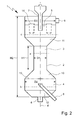
- FIG. 2 a preferred embodiment of the countercurrent filter device 1 according to the invention.
- the water inlet region 4 thus has at least one water inlet 8 or the water outlet region 5 thus has at least one water outlet 9.
- the water to be treated and / or purified and the adsorbent material should be countercurrently and / or oppositely directed and / or contacted with each other.
- the countercurrent filter device according to the invention is, as in Fig. 1 illustrated, in particular designed such that the adsorption and / or countercurrent zone 3 is at least substantially tubular and / or in the form of a tube.
- the ratio of the height H1 to the diameter D1 of the adsorption and / or countercurrent zone 3 is at least 1.5: 1, in particular at least 2: 1, preferably at least 2.5: 1 , preferably at least 3: 1.
- the ratio of the height H1 to the diameter D1 of the adsorption and / or countercurrent zone 3 [ratio height H1: diameter D1] should be in the range from 1.5: 1 to 20: 1, in particular 2 : 1 to 15: 1, preferably 2.5: 1 to 10: 1, preferably 3: 1 to 8: 1, is located.
- the countercurrent filter device 1 of the adsorption and / or countercurrent zone 1 should have a height H1 of at least 0.5 m, in particular at least 0.75 m, preferably at least 1 m, preferably at least 2 m, particularly preferably at least 3 m.
- the adsorption and / or countercurrent zone 3 should have a height H1 in the range of 0.5 m to 10 m, in particular in the range of 0.75 m to 8 m, preferably 1 m to 7 m, preferably 2 m to 7 m, more preferably 3 m to 5 m.
- the adsorption and / or countercurrent zone 3 of the countercurrent filter device 1 should have a diameter D1 of not more than 2.5 m, in particular not more than 2 m, preferably not more than 1.5 m, preferably not more than 1.25 m, particularly preferably not more than 1 m. exhibit.
- the adsorption and / or countercurrent zone should have a diameter D1 in the range of 0.05 m to 2.5 m, in particular in the range of 0.1 m to 2 m, preferably 0.25 m to 1.5 m, preferably 0 , 5m to 1.25m, more preferably 0.5m to 1m.
- the ratio of the total height H2 of the countercurrent filter device 1 to the height H1 of the adsorption and / or countercurrent zone 3 is at least 1.25: 1, in particular at least 1.5: 1, preferably at least 1.75: 1, preferably at least 2: 1.
- the ratio of the total height H2 of the counterflow filter device 1 to the height H1 of the adsorption and / or countercurrent zone 3 [ratio total height H2: height H1] should be at most 5: 1, in particular not more than 4.75: 1, preferably not more than 4.5: 1, preferably not more than 4: 1.
- ratio of the total height H2 of the countercurrent filter device 1 to the height H1 of the adsorption and / or countercurrent zone 3 should be in the range from 1.25: 1 to 5: 1, in particular 1.5: 1 to 4.75: 1, preferably 1.75: 1 to 4.5: 1, preferably 2: 1 to 4: 1.
- the ratio of the diameter D1 of the adsorption and / or countercurrent zone 3 to the diameter D2 of the water inlet region 4 is at least 1: 1.1, in particular at least 1: 1.25, preferably at least 1: 1.5, preferably at least 1: 1.75, more preferably at least 1: 2.
- the ratio of the diameter D1 of the adsorption and / or countercurrent zone 3 to the diameter D3 of the water outlet region 5 is at least 1: 1.1, in particular at least 1: 1.25, preferably at least 1: 1 , 5, preferably at least 1: 1.75, more preferably at least 1: 2.
- the adsorption and / or counterflow zone 3 has an at least substantially circular and / or circular cross-section a.
- the water inlet region 4 should also have an at least substantially circular and / or circular cross-section b.
- the water outlet region 5 has an at least substantially circular and / or circular cross-section c.
- the cross-sectional area a of the adsorption and / or counterflow zone 3 is smaller than the cross-sectional area b of the water inlet area 4 and / or smaller than the cross-sectional area c of the water outlet area 5.
- the cross-sectional area b of the water inlet area 4 and the cross-sectional area c of the water outlet area 5 are at least substantially the same size.
- a taper or a smaller diameter or a smaller cross-sectional area is thus to some extent present in comparison to the water inlet region 4 or the water outlet region 5, which is particularly the case an optimization of the present in the adsorption or countercurrent zone 3 flows or mass transfer or material flows of water and adsorbent leads, especially with regard to the prevention or reduction of turbulence or the like or with regard to the avoidance of so-called dead zones reduced or Non-existing flow, along with the formation of a stable bed of adsorbent material and an optimization of the contacting of water on the one hand and adsorbent on the other. In addition, this can also implement large empty pipe or filter speeds.
- the adsorption and / or countercurrent zone 3, the water inlet region 4 and / or the water outlet region 5 are arranged such that the at least substantially circular and or circular cross section a of the adsorption and / or countercurrent zone 3, the at least substantially circular and / or circular cross section b of the water inlet region 4 and / or the at least substantially circular and / or circular cross section c of the water outlet region 5 at least in the Essentially concentric along the longitudinal axis d of the countercurrent filter device 1 are arranged.
- the countercurrent filter device 1 has a first transition region 10.
- the first transition region 10 should be arranged fluidically between the water inlet region 4 and the adsorption and / or countercurrent zone 3.
- the first transition region 10 should be located downstream of the water inlet region 4 and upstream of the adsorption and / or countercurrent zone 3, with respect to the direction of flow of the water.
- first transition region 10 is frusto-conical and / or conical.
- first transitional region 10 starting from the water inlet region 4 with the diameter D2, tapers in the direction of the adsorption and / or countercurrent zone 3 with the diameter D1, which likewise brings about flow-related advantages since, as it were, a funnel function is provided for focussing the water flow ,
- the countercurrent filter device 1 has a second transition region 11.
- the second transition region 11 should be arranged fluidically between the water outlet region 5 and the adsorption and / or countercurrent zone 3.
- the second transition region 11 should be located downstream of the adsorption and / or countercurrent zone 3 upstream of the water outlet region 5, with respect to the direction of flow of the water.
- the second transition region 11 is frusto-conical or conical.
- the second transition region 11 tapers from the water outlet region 5 with the diameter D3 in the direction of the adsorption and / or countercurrent zone 3 with the diameter D1.
- the second transition region 11 leads in particular to an optimized supply of the adsorption material into the adsorption or countercurrent zone and to obtain a uniform or optimally structured bed of the adsorption material.
- the respective transition regions 10, 11 thus taper, in particular starting from the diameter D 2, D 3 of the water inlet region 4 or the water outlet region 5, to the diameter D 1 of the adsorption and / or countercurrent zone 3.
- the water inlet 8 of the countercurrent filter device 1 it should be arranged such that the defined by the opening of the water inlet 8 cross-sectional area is at least substantially perpendicular to the longitudinal axis d of the countercurrent filter device positioned. As a result, the water can be optimally introduced into the device.
- the countercurrent filter device 1, in particular the water inlet region 4 has at least one distributor device 13.
- the distribution device 13 should be arranged fluidically between the water inlet 8 of the water inlet region 4 and the adsorption and / or countercurrent zone 3 and / or between the water inlet 8 of the water inlet region 4 and the first transition region 10.
- the manifold 13 should be located downstream of the water inlet 8 and / or downstream of the adsorbent outlet 6, preferably downstream of the water inlet 8 and the adsorbent outlet 6, with respect to the direction of flow of the water.
- the distribution device 13 is arranged in particular upstream of the water inlet 8 and / or the adsorbent material outlet 6, with respect to the transport direction of the adsorption material.
- the presence of a distributor device 13 optimizes the entry of the water to be treated or purified into the adsorption or counterflow zone 3, which further optimizes the filter performance of the countercurrent filter device 1 according to the invention.
- the distribution device 13 should be at least substantially continuous and / or permeable to the water to be treated and / or purified.
- the distributor device 13 should be at least substantially continuous and / or permeable to the particulate adsorption material, i. H.
- the distribution device 13 should have openings and / or pores which are larger than the particle size of the adsorption filter material, so that the spent adsorption material can pass from the adsorption and / or countercurrent zone 3 to the outlet 6.
- networks or grids can be used.
- the water inlet 8 of the water inlet region 4 may be equipped with a covering device.
- a cover device can be assigned to the water inlet of the water inlet region.
- the covering device should be arranged fluidically between the water inlet of the water inlet region and the adsorption and / or countercurrent zone and / or between the water inlet of the water inlet region and the first transition region.
- the cover should be part of the distribution device or be formed by the distribution device.
- the covering device prevents the penetration of adsorption material into the water inlet, in particular in the event that the countercurrent filter device is not in operation or the influx of water is interrupted.
- the adsorbent material outlet 6 should be arranged downstream of the water inlet 8 of the water inlet region 4, based on the transport direction of the adsorption material. In other words, the adsorbent material outlet 6 should be located upstream of the water inlet 8 of the water inlet region 4, with respect to the flow direction of the water. In addition, the adsorption material outlet 6 should be arranged in an end section 12 of the water inlet region 4. In particular, the adsorbent material outlet 6 should be arranged at a first end of the counterflow filter device 1.
- the end portion 12 is arranged downstream of the water inlet 8, based on the transport direction of the adsorption material.
- the end portion should be frusto-conical and / or conical.
- the end portion tapers in the direction of the adsorbent material outlet 6. In this way, a funneling function with respect to the adsorbent material to be removed is effectively provided.
- the adsorbent material outlet 6 should be arranged such that the cross-sectional area defined by the opening of the adsorbent material outlet 6 is positioned at least substantially perpendicular to the longitudinal axis d of the countercurrent filter apparatus 1, which improves the removal of the adsorption filter material.
- the adsorbent material inlet 7 should be arranged upstream of the water outlet 9 of the water outlet region 5.
- the water outlet 9 of the water outlet region 5 should be arranged downstream of the adsorption material inlet 7, in each case with respect to the direction of flow of the water.
- the countercurrent filter device 1, in particular the water outlet region 5 has at least one separating device 14.
- the separating device 14 fluidly between the water outlet 9 of the water outlet region 5 and the adsorption and / or countercurrent zone 3 and / or between the water outlet 9 of the water outlet region 5 and the second Transition region 11 is arranged.
- the separator 14 should be located upstream of the water outlet 9 and / or downstream of the adsorbent inlet 7, preferably upstream of the water outlet 5 and downstream of the adsorbent inlet 7.
- the separating device 14 should be fluidly arranged between the water outlet 9 and the adsorbent inlet 7 in this connection.
- the separating device 14 prevents the penetration of adsorption material into the water outlet 9 or into the filtrate to be removed.
- the separating device 14 should be at least substantially continuous and / or permeable to the water to be treated and / or purified. In addition, the separating device 14 should be at least substantially non-continuous and / or impermeable to the particulate adsorption material.
- the separator 14 comprises at least one filter element or consists thereof.
- This may be, for example, a filter fabric or the like.
- the pore or mesh size or the size of the passage openings of the filter element should be smaller than the particle or grain size of the adsorption material.
- the adsorption material inlet 6 is arranged such that the cross-sectional area defined by the opening of the adsorption material inlet 6 is positioned at least substantially perpendicular to the longitudinal axis d of the countercurrent filter device 1.
- the countercurrent filter device 1 is at least substantially vertically arranged and / or aligned, in particular in the operating and / or application state, with respect to the longitudinal axis d of the countercurrent filter device 1.
- the water inlet region 4 is thus arranged in a manner below or forms a lower end.
- the water outlet area 5 is arranged at the top, so to speak, or forms an upper end.
- the water to be treated and / or purified flows from the lower water inlet region 4 through the adsorption and / or countercurrent zone 3 to the upper water outlet region 5 and / or is guided.
- the water to be treated and / or purified can flow from below and / or from the lower end through the adsorption and / or countercurrent zone 3 upwards and / or to the upper end and / or guided ,
- the adsorption material passes from the upper water outlet region 5 through the adsorption and / or countercurrent zone 3 to the lower water.
- Inlet 4 is guided.
- the adsorption material should be guided from above and / or from the upper end through the adsorption and / or countercurrent zone downwards and / or to the lower end.
- the adsorption material in the countercurrent filter device 1 should be present in the countercurrent filter device 1, in particular in the adsorption and / or countercurrent zone 3 in the form of a bed.
- the presence of the particulate adsorption material in the form of a particular loose bed is associated with the advantage that on the one hand optimal Throughflow of the adsorption material is realized with the water to be treated or purified and that on the other hand, the adsorption material can be removed as such very well from the bed or the bed can be added.
- the countercurrent filter device 1 may be formed such that in the operating and / or application state, an empty tube speed and / or filter speed , calculated as the quotient of volume flow [m 3 / h] and cross-sectional area [m 2 ], based on the adsorption and / or countercurrent flow zone and based on the water to be treated and / or purified, of at least 10 m / h, in particular at least 20 m / h, preferably at least 25 m / h, preferably at least 30 m / h, is present or set.
- the countercurrent filter device 1 is designed such that in the operating and / or application state an empty tube velocity and / or filter velocity, calculated as the quotient of volume flow [m 3 / h] and cross sectional area [m 2 ], based on the adsorption and / or countercurrent flow zone and, based on the water to be treated and / or purified, in the range of 10 m / h to 120 m / h, in particular 20 m / h to 100 m / h, preferably 25 m / h to 80 m / h, preferably 30 m / h to 70 m / h, particularly preferably 40 m / h to 60 m / h, is present or set.
- the countercurrent filter device 1 according to the invention is designed in such a way that in the operating and / or application state, in particular a filtrate specific mass flow rate, calculated as the quotient of mass flow rate of adsorption material in the countercurrent filter device [g / h] and volume of purified water and / or filtrate [m 3 ], in the range from 10 -7 g / h ⁇ m 3 to 1,000 g / h ⁇ m 3, in particular 10 -6 g / h ⁇ m 3 to 100 g / h ⁇ m 3, preferably 10 -5 g / h ⁇ m 3 to 10 g / h ⁇ m 3 is present or has been set.
- FIG. 3 the principle of the present invention underlying the opposite transport of water to be treated or purified on the one hand and of adsorption material on the other hand in the countercurrent filter device 1 according to the invention, in particular countercurrent adsorption filter column, preferably as before and contacting of water and adsorbent material, in particular in the adsorption and / or countercurrent zone 3 of the countercurrent filter device 1 according to the invention.
- Fig. 3 also illustrates the present in the operating or application state in the countercurrent filter device 1 present flow or transport of the water W on the one hand and the adsorbent AK on the other hand in countercurrent to each other.
- the water W to be treated flows from the water inlet region 4 through the adsorption or countercurrent zone 3 into the water outlet region 5, while the adsorption material, starting from the water outlet region 5 through the adsorption or countercurrent zone 3, in which the adsorption material is preferably in the form of loose fill 15, flows or is transported into the water inlet region 4.
- the method according to the invention can be carried out in particular with the aim of preferably complete removal of trace substances from a water to be purified or treated after passing through the countercurrent filter device or adsorption stage used in accordance with the invention, such a method being used, for example, in a drinking water plant for treatment or treatment .
- Purification of drinking water can be implemented.
- the water to be treated or purified, which is supplied to the countercurrent filter device in the context of the process of the invention, can be synonymous synonymous as raw water, while the purified water can be referred to as filtrate in a corresponding manner.
- the countercurrent filter device used in the context of the method according to this preferred embodiment is, for example, a counterflow filter device as defined in the corresponding device claims, which is designed in particular as a continuous countercurrent adsorption filter column.
- the corresponding countercurrent filter device in the context of the process control according to the invention in particular at least substantially vertically, based on the longitudinal axis of the countercurrent filter device, set up or operated, so that effectively an upper end and a lower end with respect to the countercurrent filter device is present or can be defined.
- the water or raw water to be treated or purified flows, in particular under pressure, into the countercurrent filter device, the water entering the countercurrent filter device to a certain extent from below or at the lower end of the countercurrent filter device .
- the countercurrent filter device may have a distributor, which is the one to be treated or processed Water or raw water into an adsorption or countercurrent zone of the countercurrent filter device leads.
- the countercurrent filter device At the same time is fed through an upper end of the countercurrent filter device or from above regenerated or unloaded adsorbent material in the form of the special activated carbon of the countercurrent filter device, this equally can be done under pressurization, wherein the related pressure for introducing the adsorbent material is greater than the pressure should be in the countercurrent filter device or in the adsorption zone.
- the adsorption material subsequently passes, as it were, from above into the adsorption or countercurrent zone, in which it forms an in particular loose bed, and in which the adsorption material, in particular in the bed, sinks or is transported from top to bottom.
- the water or raw water to be treated or purified flows in the adsorption or countercurrent zone from bottom to top and thus in countercurrent to the adsorption material, so that the removal or adsorption of micropollutants or trace contaminants from the raw water can take place in countercurrent ,
- the water is freed from the impurities and the adsorbent loaded with the impurities, wherein the adsorbent having the highest load of impurities is correspondingly in the lower region of the adsorption and / or countercurrent zone.
- the purified or freed from the trace substances or micro-pollutants water can then enter through a mechanical separator in the upper region or in the upper end and thus effectively in the head of the countercurrent filter device, wherein the purified water for further use, for example as Drinking water can be discharged or discharged from this area.
- a separation device present in the countercurrent filter device serves in particular for the retention of the adsorption material, it being possible for the relevant separating device to be designed, for example, in the form of a filter fleece or wire mesh.
- the adsorption material loaded with the impurities can be removed, for example using a jet pump, peristaltic pump or the like.
- the loaded adsorption material can be fed to a desorption apparatus or regeneration apparatus, which can comprise a plurality of units or devices.
- the adsorption material is freed from the adhering moisture or residual water before drying, for example by means of a diagonal clarifier or belt dryer. Subsequently, the adsorption material can be subjected to an additional main drying, for which purpose, for example, belt dryers and / or fluidized bed dryers can be used. As a result, in particular residual moisture, which is contained in the pore volume or space of the adsorbent be removed.
- the adsorption material thus dried and loaded with the pollutants can be supplied to thermal regeneration.
- thermal regeneration for example, devices in the form of a particular indirectly heated rotary kiln, a high-temperature fluidized bed device or a microwave oven can be used.
- the impurities are expelled or removed from the adsorption material, in particular by means of thermal energy, so that a desorption of the corresponding micropollutants takes place.
- the desorbed substances are present in particular in the gaseous state and can be a thermal end use, in particular a combustion supplied.
- the adsorption material is, as it were, restored to the original state or into an unloaded state by the thermal regeneration, so that the adsorption capacity of the adsorption material is restored.
- the thus recycled or uncharged adsorption material can be stored, for example, in a storage device and wetted by means of a suitable moistening or conveying device, such as a jet pump and / or a peristaltic pump, with water and fed again in particular under pressurization of the countercurrent filter device.
- a suitable moistening or conveying device such as a jet pump and / or a peristaltic pump
- a total of a small circulation factor in relation to the used purification plant can be realized, ie a relatively large part of the adsorption material used in the process control according to the invention is located during the process control in the countercurrent filter device, and only a relatively small part of the adsorption material is present in the regeneration section, which is associated with procedural advantages, since a high proportion of the adsorption material can fulfill the process-specific purpose of the purification of water. Likewise, high specific mass throughputs can be realized due to the process of the invention, since large amounts of filtrate can be generated in relation to the amount of adsorption material used.
- the water to be treated or purified contains on average the following impurities or trace substances: Table 1: Trace substances in the water to be treated or purified (raw water) description Average concentration at the inlet of the counterflow filter device unit amidotrizoic 290 ng / l iopamidol 97 ng / l Perfluorooctane sulfonate (PFOS) 260 Methyl tert-butyl ether (MTBE) 0.57 ug / l Dissolved Organic Carbons (DOC) 0.4-0.7 mg / l
- the countercurrent filter device used in particular as previously defined, has a height H1 of about 3.50 m with a diameter D2 or D3 of the water inlet region and the water outlet region of about 1.60 m.
- the spatial dimensions of the cylindrically formed adsorption or countercurrent zone of the countercurrent filter device also amount to 1.75 m for the height H1 and 0.8 m for the diameter D1.
- the volume of the packed bed of activated carbon used in the counterflow filter device is about 0.85 m 3 .
- the adsorption material used is a special granular activated carbon (PBSAC) with a Gurvich pore volume of 1.124 cm 3 / g and an abrasion hardness of 98.7%.
- the empty pipe or filter speed is set to a value of about 55 m / h.
- the countercurrent filter device according to the invention or the purification plant according to the invention with a circulation factor calculated as a quotient of the amount of which is in the regeneration or recycling Adsorption and amount of adsorption material located in the countercurrent filter device, proceeded from about 10.
- the countercurrent filter device according to the invention with a specific mass flow rate calculated as the quotient of mass flow rate of adsorption material and volume of treated or purified water or filtrate produced, of about 5 g / h. m 3 operated.
- the used purification plant also contains a first drying or dehumidifying device in the form of a Schräg banksers, a second drying or dehumidifying device in the form of a belt dryer and a third main drying or dehumidifying in the form of a fluidized bed dryer, which are arranged sequentially.
- the corresponding drying or dehumidifying a regeneration or desorption in the form of an indirectly heated rotary kiln is connected downstream.
- the purification plant also has a storage device downstream of the regeneration or desorption device and a humidification or transport device in the form of a water jet pump, which in turn is connected downstream of the regeneration or desorption device.
- the adsorbent taken from the countercurrent filter device and loaded with the contaminants is passed through the corresponding drying or dehumidifying devices, the residual moisture content of the adsorption material thus dried being about 0.8% by weight, based on the adsorption material. Subsequently, the adsorption material is transferred to the regeneration or desorption. There is a thermal treatment, along with the desorption of previously adsorbed impurities.
- the thus obtained purified or fresh adsorption material is temporarily stored in the storage device, subsequently moistened by means of the humidifying or transporting device, in which respect the underlying raw water is likewise used, and subsequently fed again to the countercurrent filter device.
- a breakthrough will be detected for amidotrizoic acid after an operating time of about 118 h.
- the breakthrough time is about 125 h, while for PFOS a breakthrough time of 115 h is determined.
- a breakthrough can be determined after 72 h.
- the breakthrough time is about 65 h.
- no breakthrough can be detected over the test or operating period of 7 days.
- it can be observed that the bed of activated carbon is not completely homogeneous or uniform.
- a non-inventive filter device is used in the form of a closed with respect to the adsorbent filter system.
- the comparison filter device has a height of 2 m and a diameter of 1.50 m and contains activated carbon in the form of a packed bed with a volume of 0.85 m 3 , which is not replaced during the experimental operation.
- the adsorption material used is a particulate shaped carbon.
- the system is operated with an empty pipe or filter speed of 8 m / h, in which connection the previously defined and contaminated with the corresponding impurities raw water is used. With respect to amidotrizoic acid, breakthrough was observed after approximately 38 hours of operation.
- the breakthrough time is about 40 h, while for PFOS a breakthrough time of 42 h is determined. With regard to MTBE, a breakthrough can already be determined after 17 h. For the DOC impurities, the breakthrough time is about 21 h.
- the breakthrough behavior for relevant trace impurities on different adsorbents is determined in a pilot scale pilot plant.
- an activated carbon filter system is built from four parallel filter columns, the respective filter columns (filters 1 to 4) have a diameter of 0.095 m with a corresponding area of 0.07 m 2 .
- the adsorption material to be investigated was used in a bed height of about 1.27 m, wherein the respective amounts of activated carbon vary between 3.2 and 5.5 kg. During the test or operating period, the adsorption material is not replaced.
- the respective filter columns are operated at an empty tube or filter speed of 10 m / h.
- the first filter column was operated with a special commercially available shaped carbon, while the second to fourth filter column is operated with activated carbon in the form of PBSAC, as shown in Table 2, as regards the activated carbon PBSAC I to III, PBSAC I has the lowest and PBSAC II the highest degree of activation.
- Table 2 Product specifications of the adsorbents Filter 1 Filter 2 Filter 4 Filter 3 adsorbent conventional carbon PBSAC I PBSAC II PBSAC III BET m 2 / g 850 1506 1733 2084 iodine mg / g 850 1400 1584 1767 granulation mm 0.5 to 2.6 about 0.5 about 0.45 about 0.45 tap density kg / m 3 460 535 479 355 ash content Wt .-% 1.2 0.8 0.2 0.3
- the feed to the pilot plant is pure water, to which a mixture of different trace substances is added from a feed tank.
- amidotrizoic acid, lopamidol, PFOS, DMS, MTBE and EDTA were added.
- Table 3 shows the mean feed concentration of the trace substances: Table 3: Mean feed concentration of trace substances Feed concentration mean value amidotrizoic 290 ng / l iopamidol 97 ng / l PFOS 260ng / l MTBE 3.9 ⁇ g / l N, N-Dimethyl sulfamide (DMS) 0.8 ⁇ g / l
- the respective breakthrough curves are determined, with the respective limiting value for the breakthrough assuming a relative concentration of 0.1 (ie quotient of effluent concentration and feed concentration).
- the breakthrough time is the specific throughput (throughput of water per kg of adsorbent).
- Table 4 Breakthrough behavior of the respective trace impurities (breakthrough at specific throughput [m ⁇ sup> 3 ⁇ / sup> / kg]): Filter 1 Filter 2 Filter 4 Filter 3 activated carbons conventional carbon PBSAC I PBSAC II PBSAC III amidotrizoic 10 25 40 225 iopamidol 17 54 82 264 PFOS 20 38 60 > 234 MTBE > 5 15 37 35 DMS > 5 7 8th 7
- Table 4 illustrates that the activated carbons based on PBSAC I to III with the specifications listed in Table 2 have a significantly better breakthrough behavior than the conventional shaped carbon.
- Such activated carbons are particularly suitable for the process according to the invention or for use in the purification plant according to the invention or the counterflow filtration device according to the invention.
- the adsorption material taken off after completion of the purification in the form of the conventional shaped carbon used has a marked abrasion, accompanied by sludge formation.
Landscapes
- Chemical & Material Sciences (AREA)
- Organic Chemistry (AREA)
- Life Sciences & Earth Sciences (AREA)
- Hydrology & Water Resources (AREA)
- Engineering & Computer Science (AREA)
- Environmental & Geological Engineering (AREA)
- Water Supply & Treatment (AREA)
- Chemical Kinetics & Catalysis (AREA)
- Analytical Chemistry (AREA)
- Inorganic Chemistry (AREA)
- Water Treatment By Sorption (AREA)
Claims (15)
- Dispositif de filtration à contre-courant (1), en particulier destiné à traiter et/ou purifier de l'eau, afin d'en éliminer par adsorption des impuretés à base inorganique ou organique, et à recevoir, stocker et délivrer, en particulier en continu, au moins un matériau adsorbant de préférence particulaire,
le dispositif de filtration à contre-courant (1) possédant au moins un boîtier (2), lequel boîtier (2) possède au moins une zone d'adsorption et/ou à contre-courant (3) ainsi qu'au moins une zone d'entrée d'eau (4) et au moins une zone de sortie d'eau (5), dans lequel- la zone d'adsorption et/ou à contre-courant (3) est disposée du point de vue fluidique entre la zone d'entrée d'eau (4) et la zone de sortie d'eau (5) et/ou la zone d'adsorption et/ou à contre-courant (3) est disposée en aval de la zone d'entrée d'eau (4) et en amont de la zone de sortie d'eau (5) par rapport au sens d'écoulement de l'eau,- la zone d'entrée d'eau (4) possède au moins une arrivée d'eau (8) et au moins une sortie de matériau adsorbant (6) et la zone de sortie d'eau (5) possède au moins une évacuation d'eau (9) et au moins une entrée de matériau adsorbant (7),- le quotient du diamètre (D1) de la zone d'adsorption et/ou à contre-courant (3) par le diamètre (D2) de la zone d'entrée d'eau (4) [quotient diamètre (D1) : diamètre (D2)] est au moins égal à 1 : 1,1 et le quotient du diamètre (D1) de la zone d'adsorption et/ou à contre-courant (3) par le diamètre (D3) de la zone de sortie d'eau (5) [quotient diamètre (D1) : diamètre (D3)] est au moins égal à 1 : 1,1, et
le dispositif de filtration à contre-courant (1) possède une première zone de transition (10) et une deuxième zone de transition (11),- la première zone de transition (10) est disposée du point de vue fluidique entre la zone d'entrée d'eau (4) et la zone d'adsorption et/ou à contre-courant (3) et/ou la première zone de transition (10) est disposée en aval de la zone d'entrée d'eau (4) et en amont de la zone d'adsorption et/ou à contre-courant (3) par rapport au sens d'écoulement de l'eau, la première zone de transition (10) étant réalisée avec une forme conique et se rétrécissant depuis la zone d'entrée d'eau (4) de diamètre (D2) en direction de la zone d'adsorption et/ou à contre-courant (3) de diamètre (D1), et- la deuxième zone de transition (11) est disposée du point de vue fluidique entre la zone de sortie d'eau (5) et la zone d'adsorption et/ou à contre-courant (3) et/ou la deuxième zone de transition (11) est disposée en aval de la zone d'adsorption et/ou à contre-courant (3) et en amont de la zone de sortie d'eau (5) par rapport au sens d'écoulement de l'eau, la deuxième zone de transition (11) étant réalisée avec une forme conique et se rétrécissant depuis la zone de sortie d'eau (5) de diamètre (D3) en direction de la zone d'adsorption et/ou à contre-courant (3) de diamètre (D1). - Dispositif de filtration à contre-courant selon la revendication 1, dans lequel
dans l'état de fonctionnement et/ou d'utilisation, l'eau à traiter et/ou à purifier et le matériau de filtration par adsorption sont entraînés à contre-courant et/ou en sens inverse l'un de l'autre et/ou sont mis en contact l'un avec l'autre dans la zone d'adsorption et/ou à contre-courant (3), et/ou
le quotient de la hauteur (H1) par le diamètre (D1) de la zone d'adsorption et/ou à contre-courant (3) [quotient hauteur (H1) : diamètre (D1)] est au moins égal à 1,5 : 1 et/ou le quotient de la hauteur (H1) par le diamètre (D1) de la zone d'adsorption et/ou à contre-courant (3) [quotient hauteur (H1) : diamètre (D1)] se situe dans la plage de 1,5 : 1 à 20 : 1, et/ou
le quotient du diamètre (D1) de la zone d'adsorption et/ou à contre-courant (3) par le diamètre (D2) de la zone d'entrée d'eau (4) [quotient diamètre (D1) : diamètre (D2)] est au moins égal à 1 : 1,25 et/ou le quotient du diamètre (D1) de la zone d'adsorption et/ou à contre-courant (3) par le diamètre (D2) de la zone d'entrée d'eau (4) [quotient diamètre (D1) : diamètre (D2)] se situe dans la plage de 1 : 1,1 à 1 : 5, et/ou
le quotient du diamètre (D1) de la zone d'adsorption et/ou à contre-courant (3) par le diamètre (D3) de la zone de sortie d'eau (5) [quotient diamètre (D1) : diamètre (D3)] est au moins égal à 1 : 1,25 et/ou le quotient du diamètre (D1) de la zone d'adsorption et/ou à contre-courant (3) par le diamètre (D3) de la zone de sortie d'eau (5) [quotient diamètre (D1) : diamètre (D3)] se situe dans la plage de 1 : 1,1 à 1 : 5. - Dispositif de filtration à contre-courant selon la revendication 1 ou la revendication 2, dans lequel
la zone d'adsorption et/ou à contre-courant (3) possède une section transversale au moins pratiquement circulaire et/ou ronde (a), et/ou
la zone d'entrée d'eau (4) possède une section transversale (b) au moins pratiquement circulaire et/ou ronde, et/ou
la zone de sortie d'eau (5) possède une section transversale (c) au moins pratiquement circulaire et/ou ronde, et/ou
l'aire de section transversale (a) de la zone d'adsorption et/ou à contre-courant (3) est plus petite que l'aire de section transversale (b) de la zone d'entrée d'eau (4) et/ou plus petite que l'aire de section transversale (c) de la zone de sortie d'eau (5), et/ou
l'aire de section transversale (b) de la zone d'entrée d'eau (4) et l'aire de section transversale (c) de la zone de sortie d'eau (5) sont réalisées avec une dimension au moins pratiquement égale, et/ou
le dispositif de filtration à contre-courant (1), en particulier la zone d'entrée d'eau (4), possède au moins un système répartiteur (13), le système répartiteur (13) étant disposé en particulier du point de vue fluidique entre l'arrivée d'eau (8) de la zone d'entrée d'eau (4) et la zone d'adsorption et/ou à contre-courant (3) et/ou entre l'arrivée d'eau (8) de la zone d'entrée d'eau (4) et la première zone de transition (10), et/ou le système répartiteur (13) étant disposé en particulier en aval de l'arrivée d'eau (8) et/ou en aval de la sortie de matériau adsorbant (6), de préférence en aval de l'arrivée d'eau (8) et de la sortie de matériau adsorbant (6), par rapport au sens d'écoulement de l'eau. - Dispositif de filtration à contre-courant selon l'une des revendications précédentes, dans lequel
la sortie de matériau adsorbant (6) est disposée en aval de l'arrivée d'eau (8) de la zone d'entrée d'eau (4) et/ou la sortie de matériau adsorbant (6) est disposée dans une portion terminale de la zone d'entrée d'eau (4) par rapport au sens de transport du matériau adsorbant, et/ou la sortie de matériau adsorbant (6) est disposée à une première extrémité du dispositif de filtration à contre-courant (1), et/ou
l'entrée de matériau adsorbant (7) est disposée en amont de l'évacuation d'eau (9) de la zone de sortie d'eau (4) et/ou l'évacuation d'eau (9) de la zone de sortie d'eau (4) est disposée en aval de l'entrée de matériau adsorbant (7), à chaque fois par rapport au sens d'écoulement de l'eau, et/ou
le dispositif de filtration à contre-courant (1), en particulier la zone de sortie d'eau (5), possède au moins un système séparateur (14), le système séparateur (14) étant disposé en particulier du point de vue fluidique entre l'évacuation d'eau (9) de la zone de sortie d'eau (5) et la zone d'adsorption et/ou à contre-courant (3) et/ou entre l'évacuation d'eau (9) de la zone de sortie d'eau (5) et la deuxième zone de transition (11), et/ou le système séparateur (14) étant disposé en particulier en amont de l'évacuation d'eau (9) et/ou en aval de l'entrée de matériau adsorbant (7), de préférence en amont de l'évacuation d'eau (9) et en aval de l'entrée de matériau adsorbant (7), à chaque fois par rapport au sens d'écoulement de l'eau, et/ou le système séparateur (14) étant disposé en particulier du point de vue fluidique entre l'évacuation d'eau (9) et l'entrée d'agent adsorbant (7), et/ou
le matériau adsorbant particulaire est présent dans le dispositif de filtration à contre-courant (1), en particulier dans la zone d'adsorption et/ou à contre-courant (3), sous la forme d'un garnissage (15), en particulier sous la forme d'un garnissage en vrac. - Installation de purification (A), en particulier destinée à traiter et/ou purifier de l'eau (AW) afin d'en éliminer par adsorption des impuretés à base inorganique ou organique, l'installation (A) possédant :- au moins un dispositif de filtration à contre-courant (1) tel que défini dans une des revendications précédentes, destiné à traiter et/ou purifier de l'eau (AW) et à recevoir, stocker et délivrer, en particulier en continu, au moins un matériau adsorbant de préférence particulaire, en particulier tel que défini dans la revendication 10 ou la revendication 11, l'eau à traiter et/ou à purifier (AW) et le matériau adsorbant, dans l'état de fonctionnement et/ou d'utilisation, étant entraînés en particulier à contre-courant et/ou en sens inverse l'un de l'autre dans le dispositif de filtration à contre-courant (1),
le dispositif de filtration à contre-courant (1) possède au moins un boîtier (2), le boîtier (2) possédant au moins une zone d'adsorption et/ou à contre-courant (3) ainsi qu'au moins une zone d'entrée d'eau (4) et au moins une zone de sortie d'eau (5),
la zone d'adsorption et/ou à contre-courant (3) est disposée du point de vue fluidique entre la zone d'entrée d'eau (4) et la zone de sortie d'eau (5) et/ou la zone d'adsorption et/ou à contre-courant (3) est disposée en aval de la zone d'entrée d'eau (4) et en amont de la zone de sortie d'eau (5) par rapport au sens d'écoulement de l'eau, et
la zone d'entrée d'eau (4) possède au moins une sortie de matériau adsorbant (6) et la zone de sortie d'eau (5) possède au moins une entrée de matériau adsorbant (7),- le cas échéant au moins un système de séchage et/ou de déshumidification (T1, T2, T3) pour sécher et/ou déshumidifier le matériau adsorbant chargé par les impuretés, le système de séchage et/ou de déshumidification (T1, T2, T3) étant disposé en particulier en aval du dispositif de filtration à contre-courant (1) par rapport au sens de transport des matériau adsorbant,- au moins un système de régénération et/ou de désorption (R), en particulier pour régénérer le matériau adsorbant chargé par les impuretés et/ou pour fournir du matériau adsorbant régénéré et/ou non chargé et/ou frais, le système de régénération et/ou de désorption (R) étant disposé en particulier en aval du dispositif de filtration à contre-courant (1) et/ou en aval du système de séchage et/ou de déshumidification (T1, T2, T3), à chaque fois par rapport au sens de transport du matériau adsorbant,- le cas échéant au moins un système d'humidification (B), en particulier pour humidifier le matériau adsorbant régénéré et/ou non chargé et/ou frais, le système d'humidification (B) étant disposé en aval du système de régénération et/ou de désorption (R) par rapport au sens de transport du matériau adsorbant. - Installation de purification selon la revendication 5, dans laquelle
le système de séchage et/ou de déshumidification (T1, T2, T3) est choisi dans le groupe des sécheurs à bande, des sécheurs à lit fluidisé et des clarificateurs à tôles inclinées et leurs combinaisons et/ou le système de séchage et/ou de déshumidification (T1, T2, T3) comprend au moins un système de séchage et/ou de déshumidification principal (T2, T3), en particulier choisi parmi des sécheurs à bande et/ou des sécheurs à lit fluidisé, et le cas échéant au moins un système de pré-séchage et/ou de pré-déshumidification (T1, T2), en particulier choisi parmi des clarificateurs à tôles inclinées et des sécheurs à bande, le système de pré-séchage et/ou de pré-déshumidification (T1, T2) étant disposé en particulier en amont du système de séchage et/ou de déshumidification principal (T2, T3) par rapport au sens de transport des matériau adsorbant, et/ou
le système de régénération et/ou de désorption (R) est choisi dans le groupe des fours à chambre rotative, en particulier des fours à chambre rotative à chauffage indirect ; des fours à tapis, en particulier des fours à tapis à chauffage indirect ; des sécheurs à lit fluidisé, en particulier des sécheurs à lit fluidisé à haute température ; et des fours à micro-ondes, et/ou
le système d'humidification (B) est choisi dans le groupe des cuves malaxeuses, des tours de prilling, des humidificateurs à bande, des pompes à jet (d'eau), des pompes tubulaires et leurs combinaisons, et/ou
l'installation de purification (A) possède en outre au moins un système de stockage (V), le système de stockage (V) étant disposé en particulier en aval du système de régénération et/ou de désorption (R) et/ou en amont du système d'humidification (B) par rapport au sens de transport du matériau adsorbant, et/ou
l'installation de purification (A), dans l'état de fonctionnement et/ou d'utilisation, possède et/ou permet un flux et/ou un courant d'eau (W), en particulier avec un flux et/ou un courant d'eau à traiter et/ou à purifier (a) entrant dans le dispositif de filtration à contre-courant (1) et en particulier avec un flux et/ou un courant d'eau purifiée et/ou de filtrat (FI) sortant du dispositif de filtration à contre-courant (1), et/ou l'installation de purification (A), dans l'état de fonctionnement et/ou d'utilisation, possède et/ou permet un transport d'agent adsorbant (AK) en particulier cyclique, en particulier le flux et/ou le courant d'eau (W) et le transport d'agent adsorbant (AK) à contre-courant avancent en direction l'un de l'autre et/ou circulent en sens inverse l'un de l'autre dans le dispositif de filtration à contre-courant (1). - Procédé de traitement et/ou de purification d'eau afin d'en éliminer par adsorption des impuretés à base inorganique ou organique, dans lequel, dans un dispositif de filtration à contre-courant tel que défini dans une des revendications 1 à 4, l'eau à traiter et/ou à purifier d'une part et un matériau adsorbant, en particulier particulaire, d'autre part sont entraînés à contre-courant l'un de l'autre de telle façon que l'eau à traiter et/ou à purifier passe à travers un garnissage du matériau adsorbant présent dans le dispositif de filtration à contre-courant afin d'éliminer les impuretés par adsorption et le garnissage est changé et régénéré en enlevant le matériau adsorbant et en le faisant passer à contre-courant de l'eau à traiter.
- Procédé selon la revendication 7, dans lequel
le matériau adsorbant est introduit en continu dans le dispositif de filtration à contre-courant et/ou le matériau adsorbant est retiré en continu du dispositif de filtration à contre-courant, et/ou
le matériau adsorbant, en particulier le matériau adsorbant retiré du dispositif de filtration à contre-courant et/ou chargé par les impuretés, est amené ou soumis à une régénération continue et/ou thermique et/ou à un recyclage, en particulier avec enlèvement et/ou désorption des impuretés, et/ou le matériau adsorbant régénéré et/ou non utilisé est réintroduit en continu dans la colonne de filtration à contre-courant, et/ou
l'eau à traiter et/ou à purifier est introduite en continu dans la zone d'entrée d'eau du dispositif de filtration à contre-courant et/ou l'eau traitée et/ou purifiée, en particulier le filtrat, est enlevée en continu du dispositif de filtration à contre-courant dans la zone de sortie d'eau, et/ou
le matériau adsorbant est introduit en continu dans la zone de sortie d'eau du dispositif de filtration à contre-courant et/ou le matériau adsorbant est enlevé en continu du dispositif de filtration à contre-courant dans la zone de sortie d'eau, et/ou
l'eau à traiter et/ou à purifier d'une part et le matériau adsorbant d'autre part possèdent des sens d'écoulement au moins pratiquement opposés l'un à l'autre dans le dispositif de filtration à contre-courant, en particulier dans la zone d'adsorption et/ou à contre-courant, et/ou l'eau à traiter et/ou à purifier d'une part et le matériau adsorbant d'autre part circulent et/ou s'écoulent et/ou sont mis en contact l'un avec l'autre à contre-courant l'un de l'autre dans le dispositif de filtration à contre-courant, en particulier dans la zone d'adsorption et/ou à contre-courant. - Procédé selon la revendication 7 ou la revendication 8, dans lequel
l'eau à traiter et/ou à purifier introduite dans la colonne de filtration à contre-courant est entraînée à travers la zone d'adsorption et/ou à contre-courant du dispositif de filtration à contre-courant disposée en aval de la zone d'entrée d'eau du dispositif de filtration à contre-courant par rapport au sens d'écoulement de l'eau, et/ou
dans la zone d'adsorption et/ou à contre-courant du dispositif de filtration à contre-courant, une vitesse en tube vide et/ou une vitesse de passage dans le filtre, donnée par le quotient du débit volumétrique [m3/h] par l'aire de section transversale [m2] et rapportée à l'eau à traiter et/ou à purifier, est ajustée à au moins 10 m/h, et/ou
le matériau adsorbant est amené au moins pratiquement en continu au dispositif de filtration à contre-courant et/ou le matériau adsorbant est entraîné au moins pratiquement en continu à travers le dispositif de filtration à contre-courant et/ou le matériau adsorbant est enlevé au moins pratiquement en continu du dispositif de filtration à contre-courant, et/ou
le matériau adsorbant introduit dans la colonne de filtration à contre-courant est entraîné à travers une zone d'adsorption et/ou à contre-courant du dispositif de filtration à contre-courant disposée en aval de la zone de sortie d'eau du dispositif de filtration à contre-courant par rapport au sens d'écoulement du matériau adsorbant, et/ou
le matériau adsorbant est présent dans le dispositif de filtration à contre-courant, en particulier dans la zone d'adsorption et/ou à contre-courant du dispositif de filtration à contre-courant, sous la forme d'un garnissage, en particulier en vrac, et/ou
le matériau adsorbant, après avoir traversé et/ou parcouru la zone d'adsorption et/ou à contre-courant du dispositif de filtration à contre-courant, est enlevé du dispositif de filtration à contre-courant dans la zone d'entrée d'eau disposée en aval de la zone de sortie d'eau du dispositif de filtration à contre-courant et/ou en aval de la zone d'adsorption et/ou à contre-courant du dispositif de filtration à contre-courant, par rapport au sens d'écoulement des matériau adsorbant, par la sortie de matériau adsorbant. - Procédé selon l'une des revendications 7 à 9, dans lequel
le matériau adsorbant est choisi dans le groupe des matériaux adsorbants granulaires, en particuliersphériques, et/ou
le matériau adsorbant est choisi dans le groupe comprenant(i) du charbon actif, en particulier du charbon actif granulaire, de préférence du charbon actif sphérique et/ou en particulier du charbon actif sous la forme de PBSAC ( Polymer-based Spherical Activated Carbon) ;(ii) des zéolithes, en particulier des zéolithes naturelles et/ou synthétiques ;(iii) des tamis moléculaires, en particulier des tamis moléculaires zéolithiques, des tamis moléculaires synthétiques et/ou en particulier des tamis moléculaires synthétiques à base de carbone, d'oxydes et/ou de verres ;(iv) des particules d'oxydes métalliques et/ou de métaux ;(v) des résines échangeuses d'ions, en particulier des résines échangeuses de cations et/ou d'anions polydispersées et/ou monodispersées, en particulier de type gélifié et/ou de type macroporeux ;(vi) des oxydes inorganiques, en particulier des dioxydes de silicium, des gels de silice et/ou des oxydes d'aluminium ;(vii) des polymères organiques poreux et/ou des polymères hybrides organiques-inorganiques poreux et/ou des polymères hybrides organiques-inorganiques poreux et/ou des matériaux à réseaux métallo-organiques, en particulier de type MOF ( Metal Organic Framework), COF ( Covalent Organic Framework), ZIF ( Zeolithe Imidazolate Framework), POM ( Polymer Organic Material) et/ou OFC ;(viii) des granulés minéraux ;(ix) des clathrates ; ainsi que(x) leurs mélanges et/ou combinaisons ; et/ou
le matériau adsorbant est formé à partir de charbon actif, en particulier de charbon actif granulaire, de préférence sphérique, et/ou
le matériau adsorbant, en particulier le charbon actif de préférence granulaire, possède une taille de particule médiane, en particulier un diamètre de particule médian (D50), dans la plage de 0,01 à 2 mm, et/ou
le matériau adsorbant, en particulier le charbon actif de préférence granulaire, possède une résistance à l'abrasion au moins égale à 90 %, et/ou
le matériau adsorbant, en particulier le charbon actif de préférence granulaire, possède une résistance à la compression ou à l'éclatement (capacité de charge pondérale) par grain et/ou particule adsorbante, en particulier par bille de charbon actif, au moins égale à 5 newton et/ou le matériau adsorbant, en particulier le charbon actif de préférence granulaire, possède une résistance à la compression ou à l'éclatement (capacité de charge pondérale) par grain et/ou particule adsorbante, en particulier par bille de charbon actif, dans la plage de 10 à 50 newton. - Procédé selon l'une des revendications 7 à 10, dans lequel
le matériau adsorbant, en particulier le charbon actif de préférence granulaire, possède une surface spécifique (surface BET) au moins égale à 500 m2/g et/ou le matériau adsorbant particulaire (A), en particulier le charbon actif de préférence granulaire, possède une surface spécifique (surface BET) dans la plage de 500 à 4 000 m2/g, et/ou
le matériau adsorbant, en particulier le charbon actif de préférence granulaire, possède un volume poreux total suivant Gurvich au moins égal à 0,50 cm3/g et/ou le matériau adsorbant, en particulier le charbon actif de préférence granulaire, possède un volume poreux total suivant Gurvich dans la plage de 0,50 à 2,0 cm3/g, et/ou
le matériau adsorbant, en particulier le charbon actif de préférence granulaire, possède un volume poreux spécifique total dans la plage de 0,01 à 4,0 cm3/g, en particulier la proportion de pores de diamètre ≤ 75 A est au moins égale à 65 % et/ou le matériau adsorbant, en particulier le charbon actif de préférence granulaire, possède une proportion de micropores, en particulier de micropores de diamètre ≤ 30 A, au moins égale à 70 % rapportée au volume poreux total, en particulier au volume poreux total suivant Gurvich, et/ou
le matériau adsorbant, en particulier le charbon actif de préférence granulaire, possède une densité apparente (Bulk Density) dans la plage de 250 à 700 g/l. - Procédé selon l'une des revendications 7 à 11, dans lequel le matériau adsorbant, en particulier le matériau adsorbant chargé par les impuretés, enlevé du dispositif de filtration à contre-courant est séché et/ou soumis à une régénération continue et/ou thermique et/ou à un recyclage et le cas échéant réhumidifié, en particulier en utilisant un dispositif de régénération qui comprend :- le cas échéant au moins un système de séchage et/ou de déshumidification pour sécher et/ou déshumidifier le matériau adsorbant enlevé du dispositif de filtration à contre-courant et/ou le matériau adsorbant chargé par les impuretés,- au moins un système de régénération et/ou de désorption, en particulier pour régénérer thermiquement le matériau adsorbant enlevé du dispositif de filtration à contre-courant et/ou le matériau adsorbant chargé par les impuretés et/ou pour fournir du matériau adsorbant régénéré et/ou non utilisé,- le cas échéant au moins un système d'humidification, en particulier pour humidifier le matériau adsorbant régénéré et/ou non utilisé.
- Procédé selon l'une des revendications 7 à 12, dans lequel le matériau adsorbant enlevé du dispositif de filtration à contre-courant et/ou le matériau adsorbant chargé par les impuretés est séché, en particulier en utilisant le système de séchage et/ou de déshumidification, la teneur en humidité résiduelle du matériau adsorbant séché étant ajustée à une valeur maximale de 1 % en poids, rapportée au matériau adsorbant.
- Procédé selon l'une des revendications 7 à 13, dans lequel
le matériau adsorbant enlevé du dispositif de filtration à contre-courant et/ou le matériau adsorbant chargé par les impuretés est soumis, en particulier une fois le séchage effectué, de préférence ainsi que défini dans la revendication 12 ou la revendication 13, à une régénération et/ou désorption thermique, en particulier avec libération et/ou désorption des impuretés adsorbées dans le charbon actif, en particulier en utilisant le système de régénération et/ou de désorption, et/ou
le matériau adsorbant régénéré et/ou non utilisé est humidifié, en particulier en utilisant le système d'humidification et/ou introduit dans de l'eau et/ou le matériau adsorbant régénéré et/ou non utilisé et de préférence humidifié est introduit dans le dispositif de filtration à contre-courant, en particulier en appliquant une pression, et/ou
le procédé est effectué avec un coefficient de circulation, donné par le quotient de la quantité [kg] de matériau adsorbant qui est en cours de régénération et/ou de recyclage, en particulier dans le dispositif de régénération, et de la quantité [kg] de matériau adsorbant qui se trouve dans le dispositif de filtration à contre-courant, dans la plage de 0,1 à 100. - Utilisation d'une installation de purification telle que définie dans une des revendications 5 ou 6 et/ou d'un dispositif de filtration à contre-courant tel que défini dans une des revendications 1 à 4 et/ou d'un matériau adsorbant tel que défini dans la revendication 10 ou 11 dans un procédé de traitement et/ou de purification d'eau afin d'éliminer par adsorption des impuretés à base inorganique ou organique ainsi que défini dans une des revendications 7 à 14.
Applications Claiming Priority (4)
| Application Number | Priority Date | Filing Date | Title |
|---|---|---|---|
| DE102013004407 | 2013-03-15 | ||
| DE102013004747 | 2013-03-20 | ||
| DE201310006711 DE102013006711A1 (de) | 2013-03-15 | 2013-04-19 | Neue Konzepte für die Wasserbehandlung, insbesondere Wasseraufbereitung und/oder -aufreinigung |
| PCT/EP2014/053289 WO2014139770A1 (fr) | 2013-03-15 | 2014-02-20 | Colonne de filtration par adsorption à contre-courant pour le traitement de l'eau |
Publications (2)
| Publication Number | Publication Date |
|---|---|
| EP2931663A1 EP2931663A1 (fr) | 2015-10-21 |
| EP2931663B1 true EP2931663B1 (fr) | 2016-11-16 |
Family
ID=50437332
Family Applications (1)
| Application Number | Title | Priority Date | Filing Date |
|---|---|---|---|
| EP14705771.5A Active EP2931663B1 (fr) | 2013-03-15 | 2014-02-20 | Colonne de filtration par adsorption à contre-courant pour le traitement de l'eau |
Country Status (4)
| Country | Link |
|---|---|
| US (2) | US10093555B2 (fr) |
| EP (1) | EP2931663B1 (fr) |
| DE (2) | DE202013003676U1 (fr) |
| WO (1) | WO2014139770A1 (fr) |
Cited By (1)
| Publication number | Priority date | Publication date | Assignee | Title |
|---|---|---|---|---|
| EP4194409A4 (fr) * | 2021-10-27 | 2024-01-17 | Wintec Glovis Co., Ltd. | Système intégré pour régénération de charbon actif et traitement des eaux par vapeur surchauffée |
Families Citing this family (21)
| Publication number | Priority date | Publication date | Assignee | Title |
|---|---|---|---|---|
| DE202013003676U1 (de) * | 2013-03-15 | 2014-03-19 | BLüCHER GMBH | Neue Konzepte für die Wasserbehandlung, insbesondere Wasseraufbereitung und/oder -aufreinigung |
| KR102537198B1 (ko) * | 2014-03-31 | 2023-05-26 | 필립모리스 프로덕츠 에스.에이. | 활성탄을 포함하는 흡연 물품 및 그의 제조방법 |
| DE102014107489A1 (de) * | 2014-04-17 | 2015-10-22 | BLüCHER GMBH | Adsorptive Filtereinheit mit verlängerter Einsatz- und/oder Standzeit |
| FR3027021A1 (fr) * | 2014-10-13 | 2016-04-15 | Veolia Water Solutions & Tech | Procede de traitement d'eau par adsorption sur charbon actif et clarification, et installation correspondante. |
| CN105157143A (zh) * | 2015-08-01 | 2015-12-16 | 深圳雅达环保科技有限公司 | 多媒体空气净化一体机 |
| DE202016100447U1 (de) | 2016-01-29 | 2017-05-04 | Grünbeck Wasseraufbereitung GmbH | Filter zur Reinigung von Wasser |
| DE102016101640B4 (de) | 2016-01-29 | 2022-03-17 | Grünbeck Wasseraufbereitung GmbH | Filter zur Reinigung von Wasser und dessen Verwendung |
| DE202017106774U1 (de) * | 2017-09-27 | 2018-10-01 | BLüCHER GMBH | Anlage für die Behandlung und/oder Aufreinigung von Wasser |
| US10343155B1 (en) * | 2018-01-26 | 2019-07-09 | Earl Maltbie | Continuous resin regeneration system |
| WO2021050010A1 (fr) * | 2019-09-09 | 2021-03-18 | Ptt Exploration And Production Public Company Limited | Dispositif de décontamination de condensat |
| AT522367B1 (de) * | 2019-10-08 | 2020-10-15 | Mühlbauer Martin Dipl Ing | Anlagezur reinigung von abwasser |
| EP4094829A4 (fr) * | 2020-01-20 | 2024-04-17 | The University of Tokyo | Nouvel agent d'adsorption |
| CN111517503A (zh) * | 2020-05-15 | 2020-08-11 | 江苏阿尔法环保科技有限公司 | 一种有机废水中cod消解装置及工艺 |
| CN114426325A (zh) * | 2020-10-29 | 2022-05-03 | 中国石油天然气股份有限公司 | 复合絮凝剂及其制备方法和应用 |
| CN112939136B (zh) * | 2021-02-02 | 2022-07-08 | 中国科学院城市环境研究所 | 一种用于污水处理的流化吸附装置及流化吸附方法 |
| CN113087066B (zh) * | 2021-04-01 | 2022-03-29 | 江苏源拓环境科技有限公司 | 一种高盐废水浓缩母液处理用干燥回收设备 |
| FR3123345B1 (fr) * | 2021-05-27 | 2025-12-26 | Veolia Water Solutions & Tech | Procédé de traitement d’eau par adsorption sur charbon actif en micro-grains intégrant une régénération par micro-ondes du charbon actif. |
| CN113735375A (zh) * | 2021-08-31 | 2021-12-03 | 刘轲 | 市政园林工程绿化景观循环设备 |
| KR102425430B1 (ko) * | 2021-10-27 | 2022-07-27 | (주)윈텍글로비스 | 과열증기를 이용한 활성탄 재생 및 수처리 통합시스템 |
| WO2025245073A1 (fr) * | 2024-05-20 | 2025-11-27 | Sentinel Water Solutions, Llc | Procédés pilotes discontinus de substances polyfluoroalkylées, appareil mobile, et système et procédés de filtration grossière |
| ES2986753B2 (es) * | 2024-08-13 | 2025-10-02 | Servicios Tecnologicos De Saneamiento Y Depuracion S L | Dispositivo de filtracion de purines |
Family Cites Families (26)
| Publication number | Priority date | Publication date | Assignee | Title |
|---|---|---|---|---|
| BE622174A (fr) * | 1961-09-07 | |||
| US3436343A (en) * | 1963-10-17 | 1969-04-01 | Aqua Filter Inc | Simultaneous filtering for removal of taste,odor and turbidity |
| US3455820A (en) | 1967-05-05 | 1969-07-15 | Calgon Corp | Carbon treatment of raw sewage |
| DE2306626B2 (de) * | 1972-06-28 | 1979-11-29 | Chiyoda Kako Kensetsu K.K., Yokohama, Kanagawa (Japan) | Verfahren zum Regenerieren von verbrauchter Aktivkohle |
| JPS49114260A (fr) | 1973-03-05 | 1974-10-31 | ||
| US4212732A (en) * | 1973-08-22 | 1980-07-15 | California Institute Of Technology | Raw liquid waste treatment process |
| CA1048940A (fr) * | 1974-07-31 | 1979-02-20 | Gunther Gappa | Epuration controlee de l'eau au charbon active par l'analyse du charbon en presence dans l'eau |
| JPS5428231B2 (fr) * | 1974-08-06 | 1979-09-14 | ||
| JPS5385574A (en) * | 1976-12-31 | 1978-07-28 | Takeda Chemical Industries Ltd | Method of continuously regenerating filter medium and waste filter medium and apparatus therefor |
| US4293423A (en) * | 1977-10-18 | 1981-10-06 | Rohm And Haas Company | Process and apparatus for ion exchange by use of thermally regenerable resin |
| US4257896A (en) * | 1978-05-24 | 1981-03-24 | Takeda Chemical Industries, Ltd. | Countercurrent liquid-solid contacting apparatus |
| US4279755A (en) * | 1980-02-26 | 1981-07-21 | Alexander Himsley | Continuous countercurrent ion exchange process |
| DE3203181A1 (de) * | 1982-01-30 | 1983-08-04 | Degussa Ag, 6000 Frankfurt | Vorrichtung und verfahren zum kontinuierlichen kontaktieren einer fluessigen phase mit einer festen phase im gegenstrom |
| DE8815345U1 (de) | 1988-12-09 | 1990-01-18 | Osberma Osberghauser Sondermaschinenbau GmbH, 51766 Engelskirchen | Wasseraufbereiter |
| DE4000142A1 (de) * | 1990-01-04 | 1991-07-11 | Rheinische Braunkohlenw Ag | Verfahren zur kontinuierlichen reinigung von abwasser |
| FR2723935B1 (fr) * | 1994-08-26 | 1997-01-03 | Atochem Elf Sa | Procede pour abaisser la teneur en cations multivalents de solutions aqueuses |
| DE19631650A1 (de) * | 1996-08-05 | 1998-02-12 | Christoph Schmid | Adsorbersystem |
| DE19834945A1 (de) * | 1998-08-03 | 2000-02-17 | Buck Werke Gmbh & Co I K | Verfahren und Vorrichtung zur Reinigung und Wiederverwendung von tensidhaltigen Abwässern |
| EP1241173B1 (fr) | 1999-04-13 | 2004-09-08 | Mitsui Chemicals, Inc. | Procédé de purification d'oxydes de phosphines |
| DE202006016898U1 (de) | 2006-10-12 | 2007-11-22 | BLüCHER GMBH | Hochleistungsadsorbentien auf der Basis von Aktivkohle mit hoher Mikroporosität |
| DE102007050971B4 (de) * | 2007-03-14 | 2014-12-31 | BLüCHER GMBH | Verfahren zur Herstellung von Hochleistungsadsorbentien auf der Basis von Aktivkohle mit hoher Meso- und Makroporosität, Hochleistungsadsorbentien und deren Verwendung |
| DE102008005218A1 (de) | 2007-11-04 | 2009-05-07 | BLüCHER GMBH | Sorptionsfiltermaterial und seine Verwendung |
| JP2009182391A (ja) | 2008-01-29 | 2009-08-13 | Softbank Mobile Corp | 通信システム |
| DE102008041164B4 (de) | 2008-08-11 | 2011-01-13 | Werthmann, Christine, Dr. | Verfahren zur Aufbereitung von Wasser |
| DE102010024990A1 (de) * | 2010-02-15 | 2011-08-18 | Blücher GmbH, 40699 | Agglomerate von Adsorberpartikeln |
| DE202013003676U1 (de) * | 2013-03-15 | 2014-03-19 | BLüCHER GMBH | Neue Konzepte für die Wasserbehandlung, insbesondere Wasseraufbereitung und/oder -aufreinigung |
-
2013
- 2013-04-19 DE DE202013003676.1U patent/DE202013003676U1/de not_active Expired - Lifetime
- 2013-04-19 DE DE201310006711 patent/DE102013006711A1/de not_active Ceased
-
2014
- 2014-02-20 US US14/777,178 patent/US10093555B2/en active Active
- 2014-02-20 EP EP14705771.5A patent/EP2931663B1/fr active Active
- 2014-02-20 WO PCT/EP2014/053289 patent/WO2014139770A1/fr not_active Ceased
-
2018
- 2018-05-31 US US15/994,569 patent/US11198624B2/en not_active Expired - Fee Related
Non-Patent Citations (1)
| Title |
|---|
| None * |
Cited By (1)
| Publication number | Priority date | Publication date | Assignee | Title |
|---|---|---|---|---|
| EP4194409A4 (fr) * | 2021-10-27 | 2024-01-17 | Wintec Glovis Co., Ltd. | Système intégré pour régénération de charbon actif et traitement des eaux par vapeur surchauffée |
Also Published As
| Publication number | Publication date |
|---|---|
| DE102013006711A1 (de) | 2014-09-18 |
| US11198624B2 (en) | 2021-12-14 |
| US20180273400A1 (en) | 2018-09-27 |
| WO2014139770A1 (fr) | 2014-09-18 |
| DE202013003676U1 (de) | 2014-03-19 |
| US20160031722A1 (en) | 2016-02-04 |
| EP2931663A1 (fr) | 2015-10-21 |
| US10093555B2 (en) | 2018-10-09 |
Similar Documents
| Publication | Publication Date | Title |
|---|---|---|
| EP2931663B1 (fr) | Colonne de filtration par adsorption à contre-courant pour le traitement de l'eau | |
| EP2125169B1 (fr) | Procédé et dispositif d'épuration de gaz résiduaires d'un processus de frittage de minerais et/ou d'autres matériaux métallifères dans la production de métaux | |
| EP0075298B1 (fr) | Procédé et dispositif pour la purification biologique d'eau résiduaire | |
| CN102548911B (zh) | 包括多个生物反应器区段的经悬浮介质膜生物反应器系统及方法 | |
| US20100255559A1 (en) | Apparatus and process for treating an aqueous solution containing biological contaminants | |
| EP3873659A1 (fr) | Procédé pour éliminer des composés organiques polyfluorés présents dans de l'eau au moyen d'un adsorbant et pour régénérer ce dernier | |
| WO2019063150A1 (fr) | Procédé et installation pour le traitement et/ou la purification de l'eau | |
| DE3883909T2 (de) | Luftreinigungsverfahren. | |
| CN206886909U (zh) | 自动反冲洗高效活性炭净化器 | |
| EP1565918A1 (fr) | Procede de traitement d'eaux radioactives | |
| JP7796127B2 (ja) | オゾンの添加と組み合わせた活性炭への吸着による水の処理方法、および当該方法を実施するための設備 | |
| CN203999226U (zh) | 一种印刷线路板清洗废水一体化综合处理机 | |
| DE102013214514B4 (de) | Verfahren und Anlage zur Behandlung PFC-belasteter wässriger Medien | |
| CN108128925B (zh) | 一种同时去除cod及总磷的方法 | |
| EP0796822B1 (fr) | Procédé pour la purification des eaux contenant des composés organiques | |
| EP4208282B1 (fr) | Recirculation des matières valorisables de la purification de gaz d'échappement | |
| EP0411412B1 (fr) | Procédé et dispositif pour régénérer du charbon actif chargé de métaux lourds | |
| CN109796105A (zh) | 一种高难度有机废水处理工艺 | |
| DE102019116411B4 (de) | Verfahren und Vorrichtung zur kontinuierlichen Entnahme von Filtermaterialien aus Wasserfiltern | |
| DE19524093A1 (de) | Vorrichtung und Verfahren zur Reinigung von Abwässern | |
| DE102021110765A1 (de) | Verfahren zur Reinigung von verschmutztem Wasser | |
| EP2840070A1 (fr) | Installation et procédé pour purifier de l'eau comprenant l'addition d'adsorbant et de la boue | |
| DE19934409A1 (de) | Verfahren zur Entfernung von Ammonium | |
| WO1990000525A1 (fr) | Dispositif et procede pour la purification d'eaux usees | |
| DE102023125542A1 (de) | Verfahren zur Entfernung von gelösten organischen Substanzen in Flüssigkeiten mit ultra- oder superfeinen Adsorbens in Kombination mit biologischen/chemisch-physikalischen/ adsorptiven Systemen zur Wasser- und Abwasserbehandlung |
Legal Events
| Date | Code | Title | Description |
|---|---|---|---|
| PUAI | Public reference made under article 153(3) epc to a published international application that has entered the european phase |
Free format text: ORIGINAL CODE: 0009012 |
|
| 17P | Request for examination filed |
Effective date: 20150713 |
|
| AK | Designated contracting states |
Kind code of ref document: A1 Designated state(s): AL AT BE BG CH CY CZ DE DK EE ES FI FR GB GR HR HU IE IS IT LI LT LU LV MC MK MT NL NO PL PT RO RS SE SI SK SM TR |
|
| AX | Request for extension of the european patent |
Extension state: BA ME |
|
| RIN1 | Information on inventor provided before grant (corrected) |
Inventor name: RAISER, JAN Inventor name: SCHOENFELD, RAIK |
|
| GRAP | Despatch of communication of intention to grant a patent |
Free format text: ORIGINAL CODE: EPIDOSNIGR1 |
|
| INTG | Intention to grant announced |
Effective date: 20160907 |
|
| GRAS | Grant fee paid |
Free format text: ORIGINAL CODE: EPIDOSNIGR3 |
|
| GRAA | (expected) grant |
Free format text: ORIGINAL CODE: 0009210 |
|
| AK | Designated contracting states |
Kind code of ref document: B1 Designated state(s): AL AT BE BG CH CY CZ DE DK EE ES FI FR GB GR HR HU IE IS IT LI LT LU LV MC MK MT NL NO PL PT RO RS SE SI SK SM TR |
|
| AX | Request for extension of the european patent |
Extension state: BA ME |
|
| REG | Reference to a national code |
Ref country code: GB Ref legal event code: FG4D Free format text: NOT ENGLISH |
|
| REG | Reference to a national code |
Ref country code: CH Ref legal event code: EP |
|
| REG | Reference to a national code |
Ref country code: IE Ref legal event code: FG4D Free format text: LANGUAGE OF EP DOCUMENT: GERMAN |
|
| REG | Reference to a national code |
Ref country code: AT Ref legal event code: REF Ref document number: 845730 Country of ref document: AT Kind code of ref document: T Effective date: 20161215 |
|
| REG | Reference to a national code |
Ref country code: DE Ref legal event code: R096 Ref document number: 502014001988 Country of ref document: DE |
|
| REG | Reference to a national code |
Ref country code: FR Ref legal event code: PLFP Year of fee payment: 4 |
|
| PG25 | Lapsed in a contracting state [announced via postgrant information from national office to epo] |
Ref country code: LV Free format text: LAPSE BECAUSE OF FAILURE TO SUBMIT A TRANSLATION OF THE DESCRIPTION OR TO PAY THE FEE WITHIN THE PRESCRIBED TIME-LIMIT Effective date: 20161116 |
|
| REG | Reference to a national code |
Ref country code: SE Ref legal event code: TRGR |
|
| REG | Reference to a national code |
Ref country code: NL Ref legal event code: MP Effective date: 20161116 |
|
| REG | Reference to a national code |
Ref country code: LT Ref legal event code: MG4D |
|
| PG25 | Lapsed in a contracting state [announced via postgrant information from national office to epo] |
Ref country code: NL Free format text: LAPSE BECAUSE OF FAILURE TO SUBMIT A TRANSLATION OF THE DESCRIPTION OR TO PAY THE FEE WITHIN THE PRESCRIBED TIME-LIMIT Effective date: 20161116 Ref country code: GR Free format text: LAPSE BECAUSE OF FAILURE TO SUBMIT A TRANSLATION OF THE DESCRIPTION OR TO PAY THE FEE WITHIN THE PRESCRIBED TIME-LIMIT Effective date: 20170217 Ref country code: LT Free format text: LAPSE BECAUSE OF FAILURE TO SUBMIT A TRANSLATION OF THE DESCRIPTION OR TO PAY THE FEE WITHIN THE PRESCRIBED TIME-LIMIT Effective date: 20161116 Ref country code: NO Free format text: LAPSE BECAUSE OF FAILURE TO SUBMIT A TRANSLATION OF THE DESCRIPTION OR TO PAY THE FEE WITHIN THE PRESCRIBED TIME-LIMIT Effective date: 20170216 |
|
| PG25 | Lapsed in a contracting state [announced via postgrant information from national office to epo] |
Ref country code: PL Free format text: LAPSE BECAUSE OF FAILURE TO SUBMIT A TRANSLATION OF THE DESCRIPTION OR TO PAY THE FEE WITHIN THE PRESCRIBED TIME-LIMIT Effective date: 20161116 Ref country code: ES Free format text: LAPSE BECAUSE OF FAILURE TO SUBMIT A TRANSLATION OF THE DESCRIPTION OR TO PAY THE FEE WITHIN THE PRESCRIBED TIME-LIMIT Effective date: 20161116 Ref country code: BE Free format text: LAPSE BECAUSE OF NON-PAYMENT OF DUE FEES Effective date: 20170228 Ref country code: PT Free format text: LAPSE BECAUSE OF FAILURE TO SUBMIT A TRANSLATION OF THE DESCRIPTION OR TO PAY THE FEE WITHIN THE PRESCRIBED TIME-LIMIT Effective date: 20170316 Ref country code: FI Free format text: LAPSE BECAUSE OF FAILURE TO SUBMIT A TRANSLATION OF THE DESCRIPTION OR TO PAY THE FEE WITHIN THE PRESCRIBED TIME-LIMIT Effective date: 20161116 Ref country code: RS Free format text: LAPSE BECAUSE OF FAILURE TO SUBMIT A TRANSLATION OF THE DESCRIPTION OR TO PAY THE FEE WITHIN THE PRESCRIBED TIME-LIMIT Effective date: 20161116 Ref country code: HR Free format text: LAPSE BECAUSE OF FAILURE TO SUBMIT A TRANSLATION OF THE DESCRIPTION OR TO PAY THE FEE WITHIN THE PRESCRIBED TIME-LIMIT Effective date: 20161116 |
|
| PG25 | Lapsed in a contracting state [announced via postgrant information from national office to epo] |
Ref country code: EE Free format text: LAPSE BECAUSE OF FAILURE TO SUBMIT A TRANSLATION OF THE DESCRIPTION OR TO PAY THE FEE WITHIN THE PRESCRIBED TIME-LIMIT Effective date: 20161116 Ref country code: CZ Free format text: LAPSE BECAUSE OF FAILURE TO SUBMIT A TRANSLATION OF THE DESCRIPTION OR TO PAY THE FEE WITHIN THE PRESCRIBED TIME-LIMIT Effective date: 20161116 Ref country code: RO Free format text: LAPSE BECAUSE OF FAILURE TO SUBMIT A TRANSLATION OF THE DESCRIPTION OR TO PAY THE FEE WITHIN THE PRESCRIBED TIME-LIMIT Effective date: 20161116 Ref country code: DK Free format text: LAPSE BECAUSE OF FAILURE TO SUBMIT A TRANSLATION OF THE DESCRIPTION OR TO PAY THE FEE WITHIN THE PRESCRIBED TIME-LIMIT Effective date: 20161116 Ref country code: SK Free format text: LAPSE BECAUSE OF FAILURE TO SUBMIT A TRANSLATION OF THE DESCRIPTION OR TO PAY THE FEE WITHIN THE PRESCRIBED TIME-LIMIT Effective date: 20161116 |
|
| REG | Reference to a national code |
Ref country code: DE Ref legal event code: R097 Ref document number: 502014001988 Country of ref document: DE |
|
| PG25 | Lapsed in a contracting state [announced via postgrant information from national office to epo] |
Ref country code: BG Free format text: LAPSE BECAUSE OF FAILURE TO SUBMIT A TRANSLATION OF THE DESCRIPTION OR TO PAY THE FEE WITHIN THE PRESCRIBED TIME-LIMIT Effective date: 20170216 Ref country code: SM Free format text: LAPSE BECAUSE OF FAILURE TO SUBMIT A TRANSLATION OF THE DESCRIPTION OR TO PAY THE FEE WITHIN THE PRESCRIBED TIME-LIMIT Effective date: 20161116 Ref country code: IT Free format text: LAPSE BECAUSE OF FAILURE TO SUBMIT A TRANSLATION OF THE DESCRIPTION OR TO PAY THE FEE WITHIN THE PRESCRIBED TIME-LIMIT Effective date: 20161116 |
|
| PLBE | No opposition filed within time limit |
Free format text: ORIGINAL CODE: 0009261 |
|
| STAA | Information on the status of an ep patent application or granted ep patent |
Free format text: STATUS: NO OPPOSITION FILED WITHIN TIME LIMIT |
|
| PG25 | Lapsed in a contracting state [announced via postgrant information from national office to epo] |
Ref country code: MC Free format text: LAPSE BECAUSE OF FAILURE TO SUBMIT A TRANSLATION OF THE DESCRIPTION OR TO PAY THE FEE WITHIN THE PRESCRIBED TIME-LIMIT Effective date: 20161116 |
|
| 26N | No opposition filed |
Effective date: 20170817 |
|
| REG | Reference to a national code |
Ref country code: IE Ref legal event code: MM4A |
|
| PG25 | Lapsed in a contracting state [announced via postgrant information from national office to epo] |
Ref country code: SI Free format text: LAPSE BECAUSE OF FAILURE TO SUBMIT A TRANSLATION OF THE DESCRIPTION OR TO PAY THE FEE WITHIN THE PRESCRIBED TIME-LIMIT Effective date: 20161116 |
|
| PG25 | Lapsed in a contracting state [announced via postgrant information from national office to epo] |
Ref country code: LU Free format text: LAPSE BECAUSE OF NON-PAYMENT OF DUE FEES Effective date: 20170220 |
|
| REG | Reference to a national code |
Ref country code: BE Ref legal event code: MM Effective date: 20170228 |
|
| REG | Reference to a national code |
Ref country code: FR Ref legal event code: PLFP Year of fee payment: 5 |
|
| PG25 | Lapsed in a contracting state [announced via postgrant information from national office to epo] |
Ref country code: IE Free format text: LAPSE BECAUSE OF NON-PAYMENT OF DUE FEES Effective date: 20170220 |
|
| PG25 | Lapsed in a contracting state [announced via postgrant information from national office to epo] |
Ref country code: MT Free format text: LAPSE BECAUSE OF FAILURE TO SUBMIT A TRANSLATION OF THE DESCRIPTION OR TO PAY THE FEE WITHIN THE PRESCRIBED TIME-LIMIT Effective date: 20161116 |
|
| PG25 | Lapsed in a contracting state [announced via postgrant information from national office to epo] |
Ref country code: HU Free format text: LAPSE BECAUSE OF FAILURE TO SUBMIT A TRANSLATION OF THE DESCRIPTION OR TO PAY THE FEE WITHIN THE PRESCRIBED TIME-LIMIT; INVALID AB INITIO Effective date: 20140220 |
|
| PG25 | Lapsed in a contracting state [announced via postgrant information from national office to epo] |
Ref country code: CY Free format text: LAPSE BECAUSE OF FAILURE TO SUBMIT A TRANSLATION OF THE DESCRIPTION OR TO PAY THE FEE WITHIN THE PRESCRIBED TIME-LIMIT Effective date: 20161116 |
|
| PG25 | Lapsed in a contracting state [announced via postgrant information from national office to epo] |
Ref country code: MK Free format text: LAPSE BECAUSE OF FAILURE TO SUBMIT A TRANSLATION OF THE DESCRIPTION OR TO PAY THE FEE WITHIN THE PRESCRIBED TIME-LIMIT Effective date: 20161116 |
|
| PG25 | Lapsed in a contracting state [announced via postgrant information from national office to epo] |
Ref country code: TR Free format text: LAPSE BECAUSE OF FAILURE TO SUBMIT A TRANSLATION OF THE DESCRIPTION OR TO PAY THE FEE WITHIN THE PRESCRIBED TIME-LIMIT Effective date: 20161116 |
|
| REG | Reference to a national code |
Ref country code: AT Ref legal event code: MM01 Ref document number: 845730 Country of ref document: AT Kind code of ref document: T Effective date: 20190220 |
|
| PG25 | Lapsed in a contracting state [announced via postgrant information from national office to epo] |
Ref country code: AT Free format text: LAPSE BECAUSE OF NON-PAYMENT OF DUE FEES Effective date: 20190220 |
|
| PG25 | Lapsed in a contracting state [announced via postgrant information from national office to epo] |
Ref country code: AL Free format text: LAPSE BECAUSE OF FAILURE TO SUBMIT A TRANSLATION OF THE DESCRIPTION OR TO PAY THE FEE WITHIN THE PRESCRIBED TIME-LIMIT Effective date: 20161116 Ref country code: IS Free format text: LAPSE BECAUSE OF FAILURE TO SUBMIT A TRANSLATION OF THE DESCRIPTION OR TO PAY THE FEE WITHIN THE PRESCRIBED TIME-LIMIT Effective date: 20170316 |
|
| PGFP | Annual fee paid to national office [announced via postgrant information from national office to epo] |
Ref country code: FR Payment date: 20230221 Year of fee payment: 10 Ref country code: CH Payment date: 20230307 Year of fee payment: 10 |
|
| PGFP | Annual fee paid to national office [announced via postgrant information from national office to epo] |
Ref country code: SE Payment date: 20230216 Year of fee payment: 10 Ref country code: GB Payment date: 20230221 Year of fee payment: 10 Ref country code: DE Payment date: 20230227 Year of fee payment: 10 |
|
| P01 | Opt-out of the competence of the unified patent court (upc) registered |
Effective date: 20230613 |
|
| REG | Reference to a national code |
Ref country code: DE Ref legal event code: R119 Ref document number: 502014001988 Country of ref document: DE |
|
| REG | Reference to a national code |
Ref country code: CH Ref legal event code: PL |
|
| REG | Reference to a national code |
Ref country code: SE Ref legal event code: EUG |
|
| PG25 | Lapsed in a contracting state [announced via postgrant information from national office to epo] |
Ref country code: CH Free format text: LAPSE BECAUSE OF NON-PAYMENT OF DUE FEES Effective date: 20240229 |
|
| GBPC | Gb: european patent ceased through non-payment of renewal fee |
Effective date: 20240220 |
|
| PG25 | Lapsed in a contracting state [announced via postgrant information from national office to epo] |
Ref country code: CH Free format text: LAPSE BECAUSE OF NON-PAYMENT OF DUE FEES Effective date: 20240229 |
|
| PG25 | Lapsed in a contracting state [announced via postgrant information from national office to epo] |
Ref country code: DE Free format text: LAPSE BECAUSE OF NON-PAYMENT OF DUE FEES Effective date: 20240903 |
|
| PG25 | Lapsed in a contracting state [announced via postgrant information from national office to epo] |
Ref country code: GB Free format text: LAPSE BECAUSE OF NON-PAYMENT OF DUE FEES Effective date: 20240220 |
|
| PG25 | Lapsed in a contracting state [announced via postgrant information from national office to epo] |
Ref country code: FR Free format text: LAPSE BECAUSE OF NON-PAYMENT OF DUE FEES Effective date: 20240229 |
|
| PG25 | Lapsed in a contracting state [announced via postgrant information from national office to epo] |
Ref country code: GB Free format text: LAPSE BECAUSE OF NON-PAYMENT OF DUE FEES Effective date: 20240220 Ref country code: FR Free format text: LAPSE BECAUSE OF NON-PAYMENT OF DUE FEES Effective date: 20240229 Ref country code: DE Free format text: LAPSE BECAUSE OF NON-PAYMENT OF DUE FEES Effective date: 20240903 |
|
| PG25 | Lapsed in a contracting state [announced via postgrant information from national office to epo] |
Ref country code: SE Free format text: LAPSE BECAUSE OF NON-PAYMENT OF DUE FEES Effective date: 20240221 |