EP2931663B1 - Counterflow adsorption filter column for water treatment - Google Patents
Counterflow adsorption filter column for water treatment Download PDFInfo
- Publication number
- EP2931663B1 EP2931663B1 EP14705771.5A EP14705771A EP2931663B1 EP 2931663 B1 EP2931663 B1 EP 2931663B1 EP 14705771 A EP14705771 A EP 14705771A EP 2931663 B1 EP2931663 B1 EP 2931663B1
- Authority
- EP
- European Patent Office
- Prior art keywords
- adsorption
- counter
- water
- adsorption material
- flow
- Prior art date
- Legal status (The legal status is an assumption and is not a legal conclusion. Google has not performed a legal analysis and makes no representation as to the accuracy of the status listed.)
- Active
Links
Images


Classifications
-
- C—CHEMISTRY; METALLURGY
- C02—TREATMENT OF WATER, WASTE WATER, SEWAGE, OR SLUDGE
- C02F—TREATMENT OF WATER, WASTE WATER, SEWAGE, OR SLUDGE
- C02F1/00—Treatment of water, waste water, or sewage
- C02F1/28—Treatment of water, waste water, or sewage by sorption
-
- B—PERFORMING OPERATIONS; TRANSPORTING
- B01—PHYSICAL OR CHEMICAL PROCESSES OR APPARATUS IN GENERAL
- B01D—SEPARATION
- B01D15/00—Separating processes involving the treatment of liquids with solid sorbents; Apparatus therefor
- B01D15/02—Separating processes involving the treatment of liquids with solid sorbents; Apparatus therefor with moving adsorbents
-
- B—PERFORMING OPERATIONS; TRANSPORTING
- B01—PHYSICAL OR CHEMICAL PROCESSES OR APPARATUS IN GENERAL
- B01J—CHEMICAL OR PHYSICAL PROCESSES, e.g. CATALYSIS OR COLLOID CHEMISTRY; THEIR RELEVANT APPARATUS
- B01J47/00—Ion-exchange processes in general; Apparatus therefor
- B01J47/10—Ion-exchange processes in general; Apparatus therefor with moving ion-exchange material; with ion-exchange material in suspension or in fluidised-bed form
-
- C—CHEMISTRY; METALLURGY
- C02—TREATMENT OF WATER, WASTE WATER, SEWAGE, OR SLUDGE
- C02F—TREATMENT OF WATER, WASTE WATER, SEWAGE, OR SLUDGE
- C02F1/00—Treatment of water, waste water, or sewage
- C02F1/28—Treatment of water, waste water, or sewage by sorption
- C02F1/281—Treatment of water, waste water, or sewage by sorption using inorganic sorbents
-
- C—CHEMISTRY; METALLURGY
- C02—TREATMENT OF WATER, WASTE WATER, SEWAGE, OR SLUDGE
- C02F—TREATMENT OF WATER, WASTE WATER, SEWAGE, OR SLUDGE
- C02F1/00—Treatment of water, waste water, or sewage
- C02F1/28—Treatment of water, waste water, or sewage by sorption
- C02F1/285—Treatment of water, waste water, or sewage by sorption using synthetic organic sorbents
-
- C—CHEMISTRY; METALLURGY
- C02—TREATMENT OF WATER, WASTE WATER, SEWAGE, OR SLUDGE
- C02F—TREATMENT OF WATER, WASTE WATER, SEWAGE, OR SLUDGE
- C02F1/00—Treatment of water, waste water, or sewage
- C02F1/28—Treatment of water, waste water, or sewage by sorption
- C02F1/283—Treatment of water, waste water, or sewage by sorption using coal, charred products, or inorganic mixtures containing them
-
- C—CHEMISTRY; METALLURGY
- C02—TREATMENT OF WATER, WASTE WATER, SEWAGE, OR SLUDGE
- C02F—TREATMENT OF WATER, WASTE WATER, SEWAGE, OR SLUDGE
- C02F1/00—Treatment of water, waste water, or sewage
- C02F1/42—Treatment of water, waste water, or sewage by ion-exchange
-
- C—CHEMISTRY; METALLURGY
- C02—TREATMENT OF WATER, WASTE WATER, SEWAGE, OR SLUDGE
- C02F—TREATMENT OF WATER, WASTE WATER, SEWAGE, OR SLUDGE
- C02F2101/00—Nature of the contaminant
- C02F2101/30—Organic compounds
-
- C—CHEMISTRY; METALLURGY
- C02—TREATMENT OF WATER, WASTE WATER, SEWAGE, OR SLUDGE
- C02F—TREATMENT OF WATER, WASTE WATER, SEWAGE, OR SLUDGE
- C02F2209/00—Controlling or monitoring parameters in water treatment
- C02F2209/40—Liquid flow rate
-
- C—CHEMISTRY; METALLURGY
- C02—TREATMENT OF WATER, WASTE WATER, SEWAGE, OR SLUDGE
- C02F—TREATMENT OF WATER, WASTE WATER, SEWAGE, OR SLUDGE
- C02F2301/00—General aspects of water treatment
- C02F2301/04—Flow arrangements
-
- C—CHEMISTRY; METALLURGY
- C02—TREATMENT OF WATER, WASTE WATER, SEWAGE, OR SLUDGE
- C02F—TREATMENT OF WATER, WASTE WATER, SEWAGE, OR SLUDGE
- C02F2303/00—Specific treatment goals
- C02F2303/16—Regeneration of sorbents, filters
Definitions
- the present invention relates to the technical field of treating water, in particular waste water or drinking water.
- the present invention relates to the technical field of treatment or purification of water in the drinking water or wastewater sector.
- the present invention relates to a process for the treatment or purification of water (raw water), in particular of waste water or drinking water, preferably for adsorptive removal of inorganic or organic, in particular organically based impurities, such as trace substances and / or micro-pollutants.
- the present invention relates to a purification plant, preferably for the treatment or purification of water, in particular waste water or drinking water. Furthermore, the present invention relates to a countercurrent filter device, in particular countercurrent adsorption filter column, which is equally suitable for the treatment or purification of water, in particular of waste water or drinking water and preferably for particular adsorptive removal of inorganic or organic, in particular organically based impurities.
- the present invention relates to the uses of the purification plant according to the invention or of the countercurrent filter apparatus according to the invention and of special adsorption materials in the process according to the invention for the treatment or purification of water, in particular of waste water or drinking water.
- micropollutants which are synonymously also referred to as trace substances or micropollutants .
- these include, in particular, pharmaceutical active ingredients or human pharmaceuticals, such as analgesics, hormonal agents or the like, which are excreted unchanged or after chemical modification in the human organism as conjugates or metabolites and subsequently, for example, enter the municipal wastewater.
- Plasticizers in particular bisphenol A
- X-ray contrast agents such as amidotrizoic acid and lopamidol
- surfactants such as perfluorinated surfactants, pesticides or the like
- MTBE methyl tert-butyl ether
- D can be cited issolved O rganic C ompounds or D issolved O rganic C arbons (DOC), which can equally be present as impurities in the water.
- the abovementioned substances or substance classes have the common feature in particular that they can have a considerable influence on the human organism even when very small amounts in the ⁇ g or even in the ng range are absorbed, for example with regard to a hormonal effect, their property endocrine disruptors as well as the development of resistances or the like.
- pharmacologically active substances which are used in veterinary medicine, enter equally into surface waters and into the groundwater, in particular by applying correspondingly contaminated manure and subsequent leaching of the fertilized agricultural areas by precipitation, so that a flushing of the corresponding micropollutants in water systems or into the groundwater.
- the conventional activated carbons used in the prior art are often not sufficiently selective and have only low mechanical stability, which can lead to premature abrasion, in particular under adverse dust or sludge formation.
- Such plants for the purification of water using conventional activated carbon also require a lot of space since the corresponding adsorption basins are designed as open long-term filters, which may have a length of more than 10 m.
- the use of large amounts of activated carbon since the activated carbons used should be used in long-term filters in a bed with a height of 2 to 3 m, so that a total of 200 m 3 to 300 m 3 of activated carbon per pool is required.
- the proposed in the prior art closed filter systems are also designed so that they have a tubular structure with a generally large diameter and high height, in particular because due to the closed filter assembly equally large activated carbon volumes in the filter system are required.
- Such pressure filtration systems often have a height to diameter ratio in the range of about 2 to 3 or less, so such systems also require a large amount of space and sometimes less than optimal flow conditions within the filter.
- the prior art pressure filter systems described have a ratio of total column height to the height of the adsorbent material in the filter of 5 to 10 or more.
- the purification systems of the prior art mentioned above are often in so far not efficient as a satisfactory purification of water to be treated can not be realized, in particular with regard to hazardous materials such as D issolved O rganic C arbons (DOC), perfluorinated surfactants such as Perfluoroctansulfat (PFOS), anti-knock agents such as methyl tert-butyl ether (MTBE), X-ray contrast agents such as lopamidol and amidotrizoic acid.
- DOC D issolved O rganic C arbons
- PFOS Perfluoroctansulfat
- MTBE methyl tert-butyl ether
- X-ray contrast agents such as lopamidol and amidotrizoic acid.
- unfavorable circulation factors are present in relation to the state of the art for the systems described there, which represent the ratio of exhausted or regenerated activated carbon to activated carbon present in the filter system and thus for purposes of purification.
- circulating factors are at most possible in the prior art which amount to 100 or more, in particular 200 to 300 or more.
- the specific one is Water throughput until breakthrough of the trace substance amidotrizoic acid at a starting concentration of 290 ng / l in the raw water to be treated about 25 m 3 / kg of activated carbon.
- the DE 40 00 142 A1 relates to a process for the continuous purification of wastewater by means of an adsorbent.
- wastewater to be purified over lignite coke or activated carbon on lignite base are passed, which are arranged in a continuously operable device or system and which are pretreated before startup with gas or liquid.
- the concerns DE 20 2010 009 493 U1 an adsorptive system based on an agglomerate having a plurality of adsorber particles, wherein the adsorber particles are fixed on a binder carrier, in particular adhered, and connected via the binder carrier to the adsorptive system, wherein the agglomerates are to have two mutually different particulate adsorption materials.
- the concerns US 4 293 423 A a continuous or semi-continuous ion exchange process in which a column is equipped with a thermally regenerable heterogeneous ion exchange resin.
- the column used is divided into a loading area, a heat transfer area and a regeneration zone for the resin used.
- added and treated liquid should flow upwardly through the loading zone, subsequently subsequently removing the treated liquid.
- loaded resin should be moved from the loading area into the regeneration area.
- the US 4,279,755 A relates to a method of absorbing ions from a liquid containing said ions onto particles of an ion exchange resin, wherein the adsorption of the ions results in an increase of the particle density.
- the process is intended to include the steps of first passing the liquid in an absorption column upwardly through a bed of particles of the ion exchange resin and then charging higher density loaded particles falling down the adsorption column into a lower portion of the absorption column. be separated.
- the concerns EP 0 085 779 A1 an apparatus for continuously contacting a liquid phase with a solid phase in countercurrent, the apparatus comprising a column, a columnar liquid phase approach ring and a conically arranged column bottom having a solid phase discharge opening below the flow ring.
- the device has an overflow for the liquid phase and Lines, which are connected to the column bottom or the Anströmring for the liquid phase.
- the DE 1 642 396 A1 relates to a process for the treatment of waste water, wherein suspended solids are first separated and wherein the sieved raw water treated with a flocculant and the supernatant water is separated from the flocculation formed and passed through activated carbon beds.
- the activated carbon beds are periodically backwashed and regenerated. According to this conception, therefore, only a discontinuous or batchwise regeneration of the activated carbon takes place, which, however, is unfavorable or detrimental in terms of process engineering since it reduces the operating times and / or requires the installation of several parallel filter components. In addition, backwashing is associated with sometimes high losses of adsorption material.
- German utility model law concerns DE 88 15 345 U1 a water processor, in particular for the treatment or supply of pollutant-free drinking water, wherein the water conditioner is equipped with a working according to the principle of reverse osmosis plate module.
- This concept is disadvantageous in that there is a less selective system which is to be operated with high energy input and the receipt of contaminated toxic residues.
- the concerns DE 10 2008 041 164 A1 a process for treating water to remove halide ions by oxidatively halogenating an organic compound added to the water, which is subsequently separated, whereby remaining chlorate, iodate and bromate ions, respectively, are converted to the corresponding halide ions, after which a renewed oxidative halogenation should take place.
- Such a method is complicated in terms of process technology and, in addition, in terms of a multiplicity of micropollutants, is not efficient.
- the concerns EP 1 044 982 A1 a water treatment method which comprises adding ozone to raw water and filtering the raw water using an ozone-resistant membrane, wherein the filtrate can be further treated with activated carbon or a reverse osmosis membrane.
- This procedurally complex purification is sometimes cost-intensive and not optimized for continuous operation, in particular as far as the use of the activated carbon is concerned.
- the object of the present invention is to provide an efficient process and corresponding plants or devices for the treatment or purification of water, such as waste water or drinking water, wherein the previously described disadvantages of the prior art are at least largely avoided or but at least toned down.
- an object of the present invention is to provide an efficient method and related equipment or devices, in particular inorganic or organic, in particular organically based impurities, such as trace substances or micropollutants are removed from a water to be treated or purified should.
- an efficient system or an efficient system with corresponding devices in particular for carrying out the method according to the invention, is to be provided, wherein overall high efficiency is to be ensured with a high purification efficiency, in particular as far as the operating time, the consumption of adsorbent for the purification of the water to be treated and the required energy input are concerned.
- a continuous or uninterrupted operation of the system or system or a continuous or uninterrupted implementation of the method should be ensured.
- a still further object of the invention is to provide a corresponding system or a purification plant, in particular for carrying out the method according to the invention, by means of which or which the adsorbent for the treatment of the water to be treated can be used efficiently and permanently, in particular with regard to extended and uninterrupted service lives of the filtering devices used in this context.
- corresponding purification plants or devices are to be provided, which as a whole should also be spatially optimized and thus save a total of space and which overall should have high environmental compatibility and an excellent ecological balance.
- Another object of the present invention is the purification plant according to the invention, preferably for the treatment or purification of water, as defined in the corresponding independent claim; Further, advantageous developments and refinements of the purification plant according to the invention are the subject of the corresponding subclaims.
- the present invention is a countercurrent filter device, in particular countercurrent adsorption filter column, preferably for the treatment or purification of water, as defined in the corresponding independent device claim; advantageous developments and refinements of the countercurrent filter device according to the invention are the subject of the respective device subclaims.
- Another object of the present invention is the use of the purification plant according to the invention or the adsorbent material used in the present invention and the countercurrent filter device according to the invention in the process according to the invention for the treatment or purification of water according to the relevant use claim.
- the present invention is thus - according to a first aspect of the present invention - a method defined in the corresponding independent claim for the treatment or purification of water, in particular waste water or drinking water, for the adsorptive removal of inorganic or organic, in particular organically based impurities, such as trace substances or micropollutants.
- the inventive method is characterized in that in a subsequently defined countercurrent filter device, in particular countercurrent adsorption filter column, the water to be treated and / or purified on the one hand and a particular particulate adsorption material on the other hand are conducted in countercurrent or opposite to each other, such that the water to be treated and / or purified by an existing in the countercurrent filter device bed of adsorbent for adsorptive removal of impurities is passed and the bed by preferably continuously removing and supplying the adsorbent is exchanged and regenerated in countercurrent to the water to be treated.
- the adsorption material is in particular continuously guided or introduced into the counterflow filter device.
- the adsorption material can be led out or removed in particular continuously from the counterflow filter device.
- the adsorbed material introduced or removed from the countercurrent filter device or charged with the contaminants is / are subjected to a particular continuous and / or in particular thermal regeneration and / or recycling becomes.
- the impurities previously taken up by the activated carbon or adsorbed can be removed or desorbed so that a regenerated or unused or fresh adsorption material results.
- the regenerated or unused or uncharged or fresh adsorption material can in particular continuously be guided or introduced into the countercurrent filter column.
- the expression "in countercurrent and / or opposite to one another", as used in the present invention, is to be understood in particular such that with respect to the water to be treated or purified on the one hand and the adsorption on the other hand, a respective mass transport or Substance flow in the sense of a countercurrent principle, ie in the opposite direction of the respective substance transports or substance flows to each other, takes place;
- the water to be treated or purified on the one hand and the adsorption material in the countercurrent filter device or in the adsorption or countercurrent zone (which may be synonymously referred to as the mass transfer zone) are in direct contact with each other, so that As a result, absorption or adsorption of substances present in the water can take place through the adsorption material, which is in particular the impurities in the water to be treated or purified, such as micropollutants or micropollutants.
- the water to be treated or purified on the one hand and the adsorbent material on the other hand flow according to the conception according to the invention in the opposite direction to each other, wherein in the respective (main) flow directions are at least substantially opposite to each other by 180 °.
- the water to be treated or purified in the operating state or application state of the countercurrent filter system generally flows from the water inlet region through the adsorption or countercurrent zone to the water outlet region of the countercurrent filter system, whereas the adsorption material from the water outlet region through the adsorption or countercurrent zone flows to or into the water inlet region of the countercurrent filter system or is transported.
- the water is directed into a lower end or into one at the lower end the countercurrent filter device arranged introduced water inlet region, while the adsorption material is introduced into an upper end of the countercurrent filter device which simultaneously defines a water outlet region.
- a flow direction results from bottom to top with respect to the water, with the purified water or filtrate at the top removed from the countercurrent filter device, while with respect to the adsorbent material Flow direction is present, so to speak, from top to bottom in the countercurrent filter device, wherein the loaded with the impurities adsorbent material is then removed at the lower end of the countercurrent filter device.
- the water to be treated or purified under pressure for example by means of (pressure) pumping devices into the countercurrent filter device or that the purified or freed water or water Filtrate is removed under application of a negative pressure, for example by using (suction) - pump devices from the countercurrent filter device.
- the adsorption material can be introduced, for example, by means of pressurization in the countercurrent filter device and / or removed by means of negative pressure from the countercurrent filter device using appropriate pumping devices.
- the pressure at the point of entry into the countercurrent filtration device should be greater than the corresponding back pressure in the countercurrent filtration device or in the adsorption and / or countercurrent zone.
- the pressure at the exit of the adsorbent material should be such that the pressure in the countercurrent filtration device or in the adsorption and / or countercurrent zone is greater than the pressure in the downstream or downstream region.
- the feed pressure of the water is preferably greater than the pressure in the countercurrent filter device or the adsorption water for the feed or purifying water or raw water to be treated. and / or countercurrent zone or that the pressure in the region downstream of the countercurrent filter device downstream of the water outlet is lower than the corresponding pressure in the countercurrent filter device or the adsorption and / or countercurrent zone.
- the transport of the adsorption material in the countercurrent filter device or in the adsorption and / or countercurrent zone this can be caused and / or assisted by the corresponding pressure or negative pressure, in particular as described above.
- the corresponding transport of the adsorption material within the countercurrent filter device or in the adsorption and / or countercurrent zone as a result or by the support of gravity, so to speak by the height of the bed itself takes place, in particular if the countercurrent filter device is arranged vertically to its longitudinal axis, along with the mass transport or material flow of the adsorption material, so to speak, from top to bottom.
- the basic idea of the present invention is to be seen in particular in that the method according to the invention is carried out in a very special countercurrent filter device, as described in detail below, wherein with respect to the transport or flow of the substance to be treated or treated water to be purified, the adsorption material used for the purification of the water is transported in the opposite direction or flows in the opposite direction, so that in the countercurrent filter device, the water flow on the one hand and the transport or flow of the adsorbent material or the Adsorptionsmaterialstrom on the other hand in countercurrent to each other.
- the water to be purified, on the one hand, and the adsorption material, on the other hand are thus guided or brought into contact with one another in the countercurrent filter device used in accordance with the invention in an opposite transport or flow direction.
- the adsorption material used according to the invention is present within the countercurrent filter device, in particular in the form of a loose bed or in the form of a traveling bed and / or in the form of a (loose) moving bed, from which adsorption material consumed in particular on the feed side of the water to be treated or purified is removed or withdrawn in particular continuously and to which on the outlet side of the purified water or filtrate regenerated or unused adsorbent material is added again, so that the above-described opposite transport process of the adsorption results in relation to the water to be treated or purified.
- the filter efficiency with respect the removal of the previously mentioned trace substances or micropollutants is significantly increased because, without wishing to be limited to this theory, the water to be treated or purified to a certain extent is always in contact with non-exhausted or regenerated or uncharged or fresh adsorption material.
- the present invention is based, as stated above, on a procedure or technique, according to which the adsorbent or the adsorbents used is in particular continuously guided by the countercurrent or countercurrent adsorption column used in the process according to the invention.
- a further advantage of the present invention resides in the fact that sometimes suspended particles or solid particles are uncritical in the raw water. Due to the continuous or permanent removal of adsorption material, the bed does not increase within the adsorption or countercurrent zone. In particular, the permanent removal and addition of adsorption material also no interruption of the water purification is necessary. In particular, consuming backwashing operations to remove spent adsorbent material is eliminated.
- the adsorption material used according to the invention achieves the correspondingly high adsorption capacities and high selectivity according to the invention in that the amounts of adsorption material used are relatively small or small, which also means corresponding regeneration the adsorption material used to a certain extent on site and thus in the context of a single system which has both devices for water treatment on the one hand and for the regeneration of the adsorption on the other.
- the regeneration of the adsorption material is thus integrated into the technological concept in the context of the present invention and makes it possible to form the overall process locally in the form of a particularly closed circuit, without having to replace significant amounts of adsorption material with new material.
- the countercurrent filter device according to the invention as used in the method according to the invention, not least due to the use of highly efficient adsorption material on a small size, since the specific amounts of adsorption material are significantly lower than the corresponding amounts, which in purification processes of the prior art must be used, and because of the design of the countercurrent filter devices according to the invention also result in high filter speeds.
- the countercurrent filter device according to the invention which is used in the context of the method according to the invention, be implemented in an overall device or in the purification plant according to the invention with a total of small footprint.
- the term “continuous” as used in the context of the present invention is to be understood very broadly and refers in particular to an embodiment of the method according to the invention, in particular the addition and removal of the adsorption material in the or the countercurrent filter device is at least substantially without (temporal) interruption.
- the term in question also includes such a procedure, according to which, in particular, there are brief interruptions in the addition or removal of the adsorption material.
- the adsorption material used in the context of the present invention which is, as described below, in particular a special activated carbon in granular or spherical form, preferably a particular continuous regeneration or desorption, in particular thermal regeneration or desorption, so that adsorption material taken from the countercurrent filter device and contaminated or loaded with the impurities is subjected to a particular thermal regeneration for removal or desorption of the previously adsorbed impurities, the purified or finely adsorbed so obtained Adsorbed material of the countercurrent adsorption filter column freed of impurities or regenerated can be fed again.
- the performance and efficiency of the method according to the invention is further increased according to the invention, in particular accompanied by a cost reduction, since the adsorbent can be recycled or reused to a certain extent - and this without interrupting the operation of the system or device according to the invention.
- Another key advantage of the method according to the invention is the fact that the method according to the invention can to a certain extent be used universally or individually adapted or tailored in relation to the respective purification requirements.
- the method according to the invention for the treatment or purification of wastewater in particular municipal wastewater, hospital and industrial wastewater or the like, are used, but also for the purification of drinking water.
- the countercurrent filter device used in the context of the method according to the invention it is designed according to one or more features of the countercurrent filter device according to the invention as defined below.
- a very special countercurrent filter device is used, which allows on the one hand and adsorption material on the other hand, based on their special apparatus construction on the contrary transport underlying the novel process.
- the counterflow filter device used in the context of the method according to the invention has at least one housing, wherein the housing has at least one adsorption and / or countercurrent zone and at least one water inlet region and at least one water outlet region.
- the adsorption and / or countercurrent zone is arranged fluidically between the water inlet region and the water outlet region.
- the adsorption and / or countercurrent zone should be located downstream of the water inlet area and upstream of the water outlet area with respect to the direction of flow of the water.
- the water inlet region has at least one water inlet and at least one adsorption material outlet. Furthermore, the water outlet region has at least one water outlet and at least one adsorption material inlet.
- the countercurrent filter device which is used in the context of the method according to the invention, thus on the one hand at least one water inlet region with at least one water inlet and at least one adsorbent outlet and on the other hand at least one water outlet region with at least one water outlet and at least one adsorption material inlet and at least one fluidically arranged between the water inlet region and the water outlet region adsorption and / or countercurrent zone.
- the water to be treated or purified or raw water is thus through in particular in the adsorption and / or countercurrent zone of the countercurrent filter device in countercurrent to the adsorption material to obtain treated or purified water, the resulting treated or purified water, in particular filtrate, subsequently from the countercurrent Filter device is removed.
- the water to be treated in the context of the process control according to the invention in the water inlet region, in particular by the water inlet, in the countercurrent filter device should be continuously guided and / or introduced in particular.
- the treated or purified water, in particular the filtrate should in particular be continuously led out and / or removed in the water outlet region, in particular by the water outlet, from the countercurrent filter device.
- the adsorption material is in particular continuously guided and / or introduced into the water outlet region, in particular through the adsorption material inlet, into the counterflow filter device.
- the adsorption material in the water outlet region, in particular through the adsorption material outlet should be led out and / or removed continuously, in particular, from the countercurrent filter device.
- the water to be treated and / or purified on the one hand and the adsorption on the other hand in the countercurrent filter device in particular in the adsorption and / or countercurrent zone, at least substantially opposite directions of flow.
- the method according to the invention is such that the water to be treated and / or purified on the one hand and the adsorption material on the other hand in the opposite direction and / or in countercurrent to each other in the countercurrent filter device, in particular in the adsorption and / or countercurrent zone, flow and / or flow and / or be contacted with each other.
- the water to be treated and / or purified is, in particular, continuously fed into and / or introduced into the countercurrent filter device, in particular under pressurization.
- the water to be treated and / or purified in the water inlet region, preferably through the water inlet, of the countercurrent filter device should be fed into and / or introduced into the countercurrent filter device.
- the procedure is such that the water to be treated or purified in the countercurrent filter column is passed through the adsorption or countercurrent zone of the counterflow filter device arranged downstream of the water inlet region of the countercurrent filter device is, based on the flow direction of the water. It is provided in particular that the water to be treated and / or purified in the adsorption and / or countercurrent zone is brought into contact with the adsorption material. In particular, it is provided according to the invention that the water to be treated and / or purified on the one hand and the adsorption material on the other hand at least substantially opposite flow directions. In particular, the water to be treated or purified on the one hand and the adsorption material, on the other hand, flow or flow in the opposite direction and / or in countercurrent to one another in the adsorption and / or countercurrent zone.
- the procedure is in particular such that the water to be treated and / or purified, in particular after passing through and / or flowing through the adsorption and / or countercurrent zone of the countercurrent filter device, into or out of a downstream zone to the water inlet region of the countercurrent filter device and / or or downstream of the adsorption and / or countercurrent zone of the countercurrent filter device, with respect to the direction of flow of the water, arranged water outlet region, in particular by a water outlet, out of the countercurrent filter device and / or removed.
- the treated or purified water or the water or filtrate freed from the impurities, in particular trace substances and / or micropollutants are, in particular, the treated or purified water or the water or filtrate freed from the impurities, in particular trace substances and / or micropollutants.
- an empty tube velocity and / or filter velocity calculated as the quotient of volume flow [m 3 / h] and cross sectional area [m 2 ] and based on the treated and / or water to be purified, of at least 10 m / h, in particular at least 20 m / h, preferably at least 25 m / h, preferably at least 30 m / h, is set or be.
- an empty tube velocity and / or filter velocity calculated as the quotient of volume flow [m 3 / h] and cross sectional area [m 2 ] and based on the treated and / or water to be purified, in the range of 10 m / h to 120 m / h, in particular 20 m / h to 100 m / h, preferably 25 m / h to 80 m / h, preferably 30 m / h to 70 m / h, particularly preferably 40 m / h to 60 m / h, is set or be.
- the adsorption material is fed at least substantially continuously to the counterflow filter device.
- the adsorbent material should be passed at least substantially continuously through the counterflow filter device.
- the adsorption material should be removed at least substantially continuously from the countercurrent filter device.
- the amount added per unit time or the volume of adsorption material added per unit time should correspond at least substantially to the amount withdrawn per unit time or to the volume of adsorption material withdrawn per unit time. In this way, an at least substantially constant quantity or a constant volume of adsorption material in the countercurrent filter device and, as a result, an at least substantially constant height of the particular loose bed of the adsorption material in the countercurrent filter device is ensured.
- the adsorbent material in the water exit region should be fed and / or introduced into the countercurrent filter device of the countercurrent filter device.
- the adsorptive material guided and / or introduced into the countercurrent filter column should be passed through an adsorption and / or countercurrent zone of the countercurrent filter apparatus downstream of the water outlet region of the countercurrent filter apparatus, based on the flow direction of the adsorption material.
- the adsorbent material in the adsorption and / or countercurrent zone should be contacted with the water to be treated and / or purified.
- the adsorption material on the one hand and the water to be treated and / or purified on the other hand should have at least substantially opposite flow directions to one another.
- the adsorption material on the one hand and the water to be treated and / or purified on the other hand should flow or flow in the opposite direction and / or in countercurrent to one another in the adsorption and / or countercurrent zone and / or be brought into contact with each other.
- the adsorption material in the countercurrent filter device in particular in the adsorption and / or countercurrent zone of the countercurrent filter device, is present in the form of a particularly loose bed.
- the adsorption material in particular after passing through and / or flowing through the adsorption and / or countercurrent zone of the countercurrent filter device in the downstream of the water outlet region of the Countercurrent filter device and / or downstream of the adsorption and / or countercurrent zone of the countercurrent filter device, based on the flow direction of the adsorbent, arranged water inlet region is led out and / or removed by the adsorbent material outlet from the countercurrent filter device.
- Another key advantage of the process control according to the invention is also to be seen in the fact that optimized specific mass flow rates can be realized, after which a relatively small amount of adsorption material leads to a large volume of purified water or filtrate.
- a specific mass throughput calculated as the quotient of mass flow rate of adsorption material in the counterflow filter device [g / h] and volume of treated and / or purified water and / or filtrate produced [m 3 ] , in the range of 10 -7 g / hm 3 to 1,000 g / hm 3 , in particular 10 -6 gm / hm 3 to 100 gm / hm 3 , preferably 10 -5 gm / hm 3 to 10 g / h ⁇ m 3 , is set.
- an exchange ie replacement of adsorption material loaded with impurities by regenerated or unladen or fresh adsorption material in the range of 0.1 to 90 wt .-%, in particular 0, From 5 to 80% by weight, preferably from 1 to 70% by weight, preferably from 1.5 to 60% by weight, particularly preferably from 2.5 to 55% by weight, very particularly preferably from 5 to 50% by weight , is carried out, based on the volume of the adsorbent in the particular loose bed and based on a period of 24 h.
- This ensures equally that not exhausted or regenerated adsorption material is present in sufficient for the treatment or purification of the raw water amount in the bed.
- the bed quasi does not exhaust in the countercurrent filter column.
- the adsorption material can be selected from the group of granular, in particular spherical, adsorption materials.
- Such adsorption materials have a particularly good behavior in the bed, in particular as regards the flow-through behavior of the water to be treated or purified, but also the transport of the adsorption material in the bed itself.
- the adsorption material can be formed from activated carbon, in particular from granular, preferably spherical, activated carbon.
- the respective adsorption materials which can be used within the scope of the process according to the invention are well known to the person skilled in the art, and the person skilled in the art is always able to use the respective adsorption material in the light of the process control according to the present invention, in particular to ensure a high adsorption efficiency and According to the invention, in particular, to select thermal regeneration.
- Activated carbons which can be used according to the invention and which can be used in particular on the basis of granular or spherical activated carbon are obtainable, for example, from Blücher GmbH, Erkrath, Germany or from Adsor-Tech GmbH, Premnitz, Germany.
- activated carbon based on the applicant itself European patent application EP 1 918 022 A1 as well as on the parallel US 2008/0107589 A1 Reference is hereby incorporated by reference in its entirety.
- the activated carbon used according to the invention can be obtained by carbonation of, in particular, synthetic starting materials or polymers with subsequent activation.
- the activated carbon used according to the invention can be obtained, for example, by carbonation and subsequent activation of gel-type sulfonated styrene / divinylbenzene copolymers, in particular sulfonated divinylbenzene-crosslinked polystyrenes, in granular form, preferably in spherical form.
- the adsorption materials used according to the invention in particular activated carbons, in addition to their excellent physical properties (ie high mechanical stability, low abrasion or low dust formation and consequently excellent transport properties both within the bed and in the context of the regeneration process) also have excellent adsorption properties in terms of to be removed from the treated or purified water impurities to be removed.
- a somewhat tailor-made activated carbon can be used, which takes into account the complexity, the molecular sizes, as well as the specific polarities of the impurities or micropollutants to be removed with the relevant influence on the adsorption behavior.
- the adsorbent materials or activated carbons used in the context of the present invention can to a certain extent be individually tailored or tailored, which leads to a further optimization of the adsorption properties.
- the adsorption material used in the context of the process according to the invention in particular the preferably granular activated carbon, can have a monodisperse particle size distribution or a heterodisperse particle size distribution.
- the adsorption material in particular the preferably granular activated carbon, particle sizes, in particular particle diameters, to be in the range from 0.001 to 5 mm, in particular 0.005 to 3 mm, preferably 0.01 to 2 mm, particularly preferably 0.015 to 1.5 mm, most preferably 0.05 to 1 mm.
- the adsorption material in particular the preferably granular activated carbon, should have average particle sizes, in particular average particle diameter (D50), in the range from 0.01 to 2 mm, in particular 0.05 to 1.5 mm, preferably 0.1 to 1 mm ,
- the corresponding particle sizes or diameters can be determined in particular on the basis of the method according to ASTM D2862-97 / 04.
- the selection of specific particle sizes or particle diameter leads in the light of the present invention on the one hand to a particularly uniform bed within the countercurrent filter apparatus and to improved transport properties of the activated carbon material, in particular in the context of the recycling or. Regeneration, but also with regard to the (transport) behavior of the adsorption material in the particular loose bed.
- the specified particle sizes lead to a further improved flow behavior of the water in the bed.
- the adsorption material in particular the preferably granular activated carbon, an abrasion resistance ( ball pan hardness ) or abrasion hardness of at least 90%, in particular at least 95%, preferably at least 97%, more preferably at least 98%, most preferably at least 99% ,
- the abrasion resistance is determined in particular according to ASTM D3802-05.
- the high abrasion resistance leads to low abrasion of the activated carbon, in particular in the context of the underlying transport operations, which extends the service life equally.
- the adsorption material in particular the preferably granular activated carbon, should have a pressure or bursting strength per adsorption particle and / or particle, in particular per activated carbon bead, of at least 5 Newton, in particular at least 10 Newton, preferably at least 20 Newton .
- the adsorption material, in particular the preferably granular activated carbon can have a pressure or bursting strength per adsorption particle and / or particle, in particular per activated carbon bead, in the range from 10 to 50 Newton, in particular 12 to 45 Newton, preferably 15 to 40 Newton, exhibit.
- the adsorption material in particular the preferably granular activated carbon, is at least substantially dust-free.
- z. B. prevents any sludge formation in the countercurrent filter device.
- the adsorption material in particular the preferably granular activated carbon, should have an ash content of at most 1% by weight, in particular at most 0.8% by weight, preferably at most 0.6% by weight, preferably at most 0.5% by weight. , more preferably at most 0.2 wt .-%, have.
- the ash content is determined in particular according to ASTM D2866-94 / 04.
- the adsorption material in particular the preferably granular activated carbon, should have a surface oxygen content of at most 10% by weight, in particular at most 8% by weight, preferably at most 6% by weight, preferably at most 5% by weight.
- the adsorption material, in particular the preferably granular activated carbon should be hydrophobic and / or have hydrophobic surface properties.
- the surface oxygen content may, in particular by means of ESCA method (E Lectron S pectroscopy for Che mical A nalysis) are determined.
- the adsorption material in particular the preferably granular activated carbon, may have a specific surface area (BET surface area) of at least 500 m 2 / g, in particular at least 750 m 2 / g, preferably at least 1,000 m 2 / g, particularly preferably at least 1,200 m 2 / g.
- the adsorption material, in particular the preferably granular activated carbon may have a specific surface area (BET surface area) in the range of 500 to 4,000 m 2 / g, in particular 750 to 3,000 m 2 / g, preferably 1,000 to 2,500 m 2 / g 1,100 to 2,000 m 2 / g.
- the determination of the BET specific surface area is basically known to the person skilled in the art. All BET surface area data refer in particular to the determination according to ASTM D6556-04. In the context of the present invention, in particular the so-called multi-point BET determination method (MP-BET) is used in a partial pressure range p / p 0 of 0.05 to 0.1 for determining the BET surface area.
- MP-BET multi-point BET determination method
- the adsorption material in particular the preferably granular activated carbon, should have an adsorption volume V ads of at least 250 cm 3 / g, in particular at least 300 cm 3 / g, preferably at least 350 cm 3 / g, particularly preferably at least 400 cm 3 / g.
- the adsorption material, in particular the preferably granular activated carbon should have an adsorption volume V ads in the range of 250 to 3,000 cm 3 / g, in particular 300 to 2,000 cm 3 / g, preferably 350 to 2,500 cm 3 / g.
- the adsorption volume V ads is a quantity well known to the person skilled in the art for characterizing the particulate adsorption materials used. The relevant determination methods are also well known to the person skilled in the art.
- the adsorption volume V ads is the weight- related adsorbed N 2 volume, which is generally determined at a partial pressure p / p 0 of 0.995.
- the adsorption material in particular the preferably granular activated carbon, should have a total pore volume according to Gurvich of at least 0.50 cm 3 / g, in particular at least 0.55 cm 3 / g, preferably at least 0.60 cm 3 / g, particularly preferably at least 0, 65 cm 3 / g, most preferably at least 0.70 cm 3 / g.
- the adsorption material in particular the preferably granular activated carbon, should have a total pore volume according to Gurvich in the range from 0.50 to 2.0 cm 3 / g, in particular 0.55 to 1.5 cm 3 / g, preferably 0.60 to 1.2 cm 3 / g, particularly preferably 0.65 to 1.0 cm 3 / g.
- Gurvich As far as the determination of the total pore volume according to Gurvich is concerned, it is a measurement or determination method known per se to a person skilled in the art. For further details regarding the determination of the total pore volume according to Gurvich can be referred to for example L. Gurvich (1915), J. Phys. Chem. Soc. Soot. 47, 805 , as well as on Lowell, S., et al., Characterization of Porous Solids and Powders: Surface Area Pore Size and Density, Kluwer Academic Publishers, Article Technologies Series, pp. 111 et seq ,
- the adsorption material in particular the preferably granular activated carbon, a total porosity in the range of 10% to 80%, in particular 20% to 75%, preferably 25% to 70%, based on the total volume of the adsorbent having.
- the adsorption material, in particular the preferably granular activated carbon a specific total pore volume in the range of 0.01 to 4.0 cm 3 / g, in particular 0.1 to 3.0 cm 3 / g, preferably 0.2 to 2.0 cm 3 / g.
- the proportion of pores with pore diameters may be ⁇ 75 ⁇ , at least 65%, in particular at least 70%, preferably at least 75%.
- the adsorption material in particular the preferably granular activated carbon, based on the total pore volume, in particular on the total pore volume according to Gurvich, a proportion of micropores, in particular on micropores with pore diameters of ⁇ 30 ⁇ , in particular ⁇ 25 ⁇ , preferably ⁇ 20 ⁇ , of at least 70%, in particular at least 75%, preferably at least 80%, preferably at least 85%, particularly preferably at least 90%.
- the micropore volume can be determined in particular according to carbon black.
- the carbon black determination method is known per se to a person skilled in the art, so that no further details are required in this regard.
- RW MAGEE Evaluation of the External Surface Area of Carbon Black by Nitrogen Adsorption, Presented at the Meeting of the Rubber Division of the American Chem. Soc., October 1994 , z. B. Referenced in: Quantachrome Instruments, AUTO-SORB-1, AS1 WinVersion 1.50, Operating Manual, OM, 05061, Quantachrome Instruments 2004, Florida, USA, pages 71 ff.
- the adsorption material in particular the preferably granular activated carbon, should have an iodine value of at least 1,000 mg / g, in particular at least 1,250 mg / g, preferably at least 1,500 mg / g.
- the adsorption material, in particular the preferably granular activated carbon should have an iodine value in the range from 1000 to 2100 mg / g, in particular from 1250 to 2050 mg / g, preferably from 1500 to 2000 mg / g.
- the iodine value is determined in particular according to ASTM D4607-94 / 99.
- the adsorption material in particular the preferably nuclear activated carbon, should have a bulk density in the range from 250 to 700 g / l, in particular from 300 to 625 g / l, preferably from 300 to 600 g / l, particularly preferably from 350 to 550 g
- the bulk density is determined according to ASTM B527-93 / 00.
- the bulk densities provided according to the invention likewise lead to an optimized behavior of the adsorption material, in particular in the loose bed, along with an optimized flow behavior of the water to be treated or purified in the bed.
- the adsorbent material used in the present invention and loaded with the impurities may be subjected to a particular thermal regeneration to obtain an unloaded regenerated material which, after undergoing regeneration, may be recycled to the countercurrent filtration device.
- the adsorption material led out and / or removed from the countercurrent filter device and / or the adsorption material loaded with the contaminants is dried in particular using the drying and / or dehumidifying device.
- the residual moisture content of the dried adsorption material can be adjusted to a value of at most 1% by weight, in particular at most 0.5% by weight, preferably at most 0.2% by weight, based on the adsorption material.
- the residual water obtained in the course of dehumidification can be re-supplied, for example, the countercurrent filter device as raw water.
- the drying can be subdivided into, in particular, successive preliminary and / or main drying steps.
- predrying for example, oblique clarifier and / or belt dryer can be used.
- oblique clarifier and / or belt dryer can be used as part of the drying.
- the supply and / or transport of the present in particular in the form of a suspension adsorption material (ie adsorbent suspended in residual water) via pipes using corresponding pumping devices and / or suspension conveyors, in particular jet pumps and / or peristaltic pumps, the aforementioned drying and / or Dehumidifying be supplied.
- the adsorptive material led out and / or removed from the countercurrent filter device can be used in particular after drying, preferably as previously defined, in particular thermal regeneration and / or desorption, in particular with release and / or desorption of the impurities adsorbed in the adsorption material, in particular using the regeneration and / or desorption, subjected.
- the procedure is such that the impurities present in the adsorption material are desorbed or the regenerated or uncharged or fresh adsorption material is obtained.
- the optionally dried adsorption material can be supplied to the regeneration or desorption device using suitable conveying devices, such as a vibrating trough, an in particular pneumatic conveying device and / or a belt device.
- the regeneration and / or desorption device according to the invention is, in particular, a preferably indirectly heated rotary kiln, a high-temperature fluidized-bed apparatus and / or a microwave oven.
- a desorbed or fresh adsorption material is obtained.
- the adsorption material in particular in the regeneration and / or desorption device, can be at temperatures in the range from 150.degree. C. to 1000.degree. C., in particular from 200.degree. C. to 950.degree. C., preferably 250.degree C is heated to 900 ° C, preferably 250 ° C to 500 ° C, in particular for a period of 1 min to 300 min, in particular 10 min to 200 min.
- the heating can be carried out, for example, under an atmosphere of inert gas or at most a slightly oxidizing atmosphere.
- the impurities released and / or desorbed in this way can be supplied to a final thermal utilization, in particular incineration, in which case combustion apparatus known per se to the person skilled in the art can be used.
- the regenerated or fresh adsorption material is cooled or introduced into a storage device or device and / or temporarily stored.
- the transport of the adsorption material freed from the contaminants from the regeneration or desorption device into the storage device can be carried out using the devices previously mentioned for transporting the adsorption material from the drying device to the regeneration or desorption device.
- the storage of the regenerated or unladen or fresh adsorption material, in particular in the previously mentioned storage device has the advantage that the amount of regenerated or uncharged or fresh adsorption material fed into the countercurrent filter device can be adjusted or metered as required.
- the regenerated or uncharged or fresh adsorption material is moistened, in particular using the moistening device, and / or introduced into water.
- appropriate conveying or humidifying devices such as jet pumps and / or peristaltic pumps, can be used.
- For the moistening of the adsorption material in particular corresponding raw water can be used.
- the conveying or moistening devices can be used equally or simultaneously for transporting the adsorption material to or into the counterflow filter device, in particular if these are jet pumps or peristaltic pumps.
- the regenerated and / or fresh and preferably moistened adsorption material obtained in this way can subsequently be reintroduced, in particular under pressure, into the countercurrent filter device, preferably via corresponding pipelines, which are connected to the adsorption material inlet of the countercurrent device ,
- the propellant water in question can likewise be taken from the raw water.
- the pumping devices used can equally be used for moistening the adsorption material.
- the process according to the invention may be carried out with a circulation factor calculated as the quotient of the amount of adsorption material [kg] present in the regeneration and / or recycling, in particular in the regeneration apparatus, and the amount of countercurrent Adsorption material [kg], in the range of 0.1 to 100, in particular 0.5 to 75, preferably 0.75 to 50, preferably 1 to 40, particularly preferably 1.25 to 30, carried out.
- a circulation factor calculated as the quotient of the amount of adsorption material [kg] present in the regeneration and / or recycling, in particular in the regeneration apparatus, and the amount of countercurrent Adsorption material [kg], in the range of 0.1 to 100, in particular 0.5 to 75, preferably 0.75 to 50, preferably 1 to 40, particularly preferably 1.25 to 30, carried out.
- the present invention likewise relates, in accordance with this aspect of the present invention, to a process for the treatment or purification of water, in particular wastewater or drinking water, preferably for the adsorptive removal of inorganic or organic, in particular organically based, impurities, such as trace substances and / or micro-pollutants.
- the process is carried out in particular as defined above, wherein water to be treated or purified is brought into contact with an especially particulate adsorption material for purposes of treatment and / or purification, the adsorption material being in particular bulk in a subsequently defined manner
- Countercurrent filter device in particular countercurrent adsorption filter column, is arranged and is flowed through by the treated and / or purified water for adsorptive removal of impurities.
- the adsorption material of the bed arranged in the counterflow filter device is in particular continuously removed and regenerated in countercurrent to the flow of the water to be treated and / or purified.
- regenerated and / or unused adsorption material preferably regenerated adsorption material, is additionally supplied in countercurrent to the flow of the water to be treated and / or purified in at least substantially equal amounts, such as adsorption material being removed from the bed.
- the method according to the invention can also be carried out using the subsequently defined purification plant according to the invention, which may comprise a regeneration apparatus and the counterflow filter apparatus according to the invention.
- the purification plant according to the invention is particularly suitable for use in the context of the previously described method according to the invention.
- the purification plant according to the invention allows the principle according to the invention, according to which the adsorbent on the one hand and the water to be treated or purified on the other hand for purposes of purification of the water or the removal of impurities such as micropollutants, from the water in countercurrent to each other are.
- the purification plant according to the invention allows a simultaneous purification of raw water and regeneration of the adsorbent material with the relevant return of the regenerated adsorbent material for further or renewed purification of raw water, so that a total provides a powerful purification plant according to the invention, which the implementation of all aspects of the method the present invention allows for a small footprint and cost-effective operation.
- the purification plant according to the invention enables optimized circulation factors, since a large proportion of the total adsorption material present in the plant can be used for the purpose of purifying raw water.
- the purification plant according to the invention Due to the special invention technical conception of the purification plant according to the invention also high specific mass flow rates are possible because, based on the amount of sorbent material used, large quantities or volumes of purified water or filtrate are obtained. Finally, the purification plant according to the invention allows efficient purification of raw water, which in particular due to the use of a special countercurrent filter device, in particular as defined below, breakthroughs of the impurities in question can be prevented and thus a highly pure filtrate can be obtained, which is especially is of high importance for the provision of drinking water.
- the principle underlying the present invention of the opposite transport of raw water on the one hand and adsorption on the other hand be implemented in the countercurrent filter device.
- the inventive countercurrent filter device with high purification of the raw water simultaneously high Leerrohr- or filter speeds, resulting in high throughputs of raw water and the recovery of large amounts of purified filtrate.
- the filter device according to the invention is characterized by a compact and thus space-saving design, especially as far as the adsorption or countercurrent zone.
- the adsorption or countercurrent zone can have a smaller diameter or a smaller cross-sectional area than the corresponding water inlet or outlet areas of the filter device according to the invention, which likewise allows or increases the increase in the empty pipe or filter speed.
- special transition regions between the adsorption and / or countercurrent zone and the water inlet region or the water outlet region are arranged, which leads to a fluidic optimization of the respective transport processes of water and adsorbent material.
- the inventive principle of the opposite transport of raw water and adsorbent material high Leerrohr- and filter speeds is beneficial, since according to the invention, to some extent always regenerated or unloaded or fresh adsorbent material is fed to the actual purification process, which high flow rates or flow rates in relation to the raw water with simultaneous efficient purification (avoidance of breakthroughs of micropollutants or micropollutants) allows.
- the present invention - according to another aspect of the present invention - the use of a purification plant, in particular as defined herein, or a countercurrent filter device, in particular as defined herein, or an adsorbent material, in particular as defined herein, in one Process for the treatment or purification of water, in particular of waste water or drinking water, preferably for the adsorptive removal of inorganic or organic, in particular organically based impurities, in particular as defined herein.
- drying and / or dehumidifying plant T1, T2, T3 of the purification plant according to the invention may be selected from the group of belt dryers, fluidized bed dryers and inclined clarifiers and combinations thereof.
- the drying and / or dehumidifying device T1, T2, T3 at least one main drying and / or main dehumidifier T2, T3, in particular selected from belt dryers and / or fluidized bed dryers, and optionally at least one pre-dehumidifying and / or pre-dehumidifying T1, T2, in particular selected from diagonal clarifiers and belt driers.
- the pre-drying and / or pre-dehumidifying device T1, T2 should be arranged upstream of the main drying and / or main dehumidifying device T2, T3, with reference to the transport direction of the adsorption material.
- drying and / or dehumidifying device T1, T2, T3 can be connected to the adsorption material outlet 6 of the counterflow filter device 1, in particular by means of a pipeline through which the adsorption material, in particular provided with residual water and present in suspension, is transported.
- the regeneration and / or desorption R may be selected from the group of rotary kilns, in particular indirectly heated rotary kilns; Belt furnaces, in particular indirectly heated belt furnaces; Fluidized bed dryers, in particular high-temperature fluidized bed dryers; and microwave ovens.
- the regeneration and / or desorption device R can also have means and / or devices for removal and / or further treatment, in particular for thermal decomposition, of desorbed and / or impurities released from the adsorption material.
- the dried adsorption material can be conducted to the regeneration or adsorption device.
- the adsorption material outlet 6 of the countercurrent filter device can be connected to the regeneration and / or desorption device R, in particular by means of a pipeline, in particular for the less preferred case according to the invention, that process without drying and / or dehumidifying device T1, T2, T3 becomes.
- the moistening device B can be selected from the group of stirred tanks, spray towers, belt humidifiers, (water) jet pumps, peristaltic pumps and combinations thereof.
- the purification plant A according to the invention may further comprise at least one storage device V, in particular for storage and / or intermediate storage of regenerated and / or unloaded and / or fresh adsorption material.
- the storage device V may be arranged downstream of the regeneration and / or desorption device R or upstream of the moistening device B, with reference to the transport direction of the adsorption material.
- the regeneration and / or desorption device R may be connected to the storage device V or the moistening device B, in particular by means of a pipeline, a vibrating transport device, an in particular pneumatic conveying device and / or belt transport device.
- the storage device V and / or the moistening device B can be connected to the adsorption material inlet of the countercurrent filter device 1, in particular by means of a pipeline.
- the purification plant A in the operating and / or application state should have and / or permit a particularly cyclic adsorbent transport or adsorbent flow AK.
- the purification plant according to the invention the countercurrent filter device according to the invention, as defined below, have.
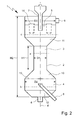
- FIG. 2 a preferred embodiment of the countercurrent filter device 1 according to the invention.
- the water inlet region 4 thus has at least one water inlet 8 or the water outlet region 5 thus has at least one water outlet 9.
- the water to be treated and / or purified and the adsorbent material should be countercurrently and / or oppositely directed and / or contacted with each other.
- the countercurrent filter device according to the invention is, as in Fig. 1 illustrated, in particular designed such that the adsorption and / or countercurrent zone 3 is at least substantially tubular and / or in the form of a tube.
- the ratio of the height H1 to the diameter D1 of the adsorption and / or countercurrent zone 3 is at least 1.5: 1, in particular at least 2: 1, preferably at least 2.5: 1 , preferably at least 3: 1.
- the ratio of the height H1 to the diameter D1 of the adsorption and / or countercurrent zone 3 [ratio height H1: diameter D1] should be in the range from 1.5: 1 to 20: 1, in particular 2 : 1 to 15: 1, preferably 2.5: 1 to 10: 1, preferably 3: 1 to 8: 1, is located.
- the countercurrent filter device 1 of the adsorption and / or countercurrent zone 1 should have a height H1 of at least 0.5 m, in particular at least 0.75 m, preferably at least 1 m, preferably at least 2 m, particularly preferably at least 3 m.
- the adsorption and / or countercurrent zone 3 should have a height H1 in the range of 0.5 m to 10 m, in particular in the range of 0.75 m to 8 m, preferably 1 m to 7 m, preferably 2 m to 7 m, more preferably 3 m to 5 m.
- the adsorption and / or countercurrent zone 3 of the countercurrent filter device 1 should have a diameter D1 of not more than 2.5 m, in particular not more than 2 m, preferably not more than 1.5 m, preferably not more than 1.25 m, particularly preferably not more than 1 m. exhibit.
- the adsorption and / or countercurrent zone should have a diameter D1 in the range of 0.05 m to 2.5 m, in particular in the range of 0.1 m to 2 m, preferably 0.25 m to 1.5 m, preferably 0 , 5m to 1.25m, more preferably 0.5m to 1m.
- the ratio of the total height H2 of the countercurrent filter device 1 to the height H1 of the adsorption and / or countercurrent zone 3 is at least 1.25: 1, in particular at least 1.5: 1, preferably at least 1.75: 1, preferably at least 2: 1.
- the ratio of the total height H2 of the counterflow filter device 1 to the height H1 of the adsorption and / or countercurrent zone 3 [ratio total height H2: height H1] should be at most 5: 1, in particular not more than 4.75: 1, preferably not more than 4.5: 1, preferably not more than 4: 1.
- ratio of the total height H2 of the countercurrent filter device 1 to the height H1 of the adsorption and / or countercurrent zone 3 should be in the range from 1.25: 1 to 5: 1, in particular 1.5: 1 to 4.75: 1, preferably 1.75: 1 to 4.5: 1, preferably 2: 1 to 4: 1.
- the ratio of the diameter D1 of the adsorption and / or countercurrent zone 3 to the diameter D2 of the water inlet region 4 is at least 1: 1.1, in particular at least 1: 1.25, preferably at least 1: 1.5, preferably at least 1: 1.75, more preferably at least 1: 2.
- the ratio of the diameter D1 of the adsorption and / or countercurrent zone 3 to the diameter D3 of the water outlet region 5 is at least 1: 1.1, in particular at least 1: 1.25, preferably at least 1: 1 , 5, preferably at least 1: 1.75, more preferably at least 1: 2.
- the adsorption and / or counterflow zone 3 has an at least substantially circular and / or circular cross-section a.
- the water inlet region 4 should also have an at least substantially circular and / or circular cross-section b.
- the water outlet region 5 has an at least substantially circular and / or circular cross-section c.
- the cross-sectional area a of the adsorption and / or counterflow zone 3 is smaller than the cross-sectional area b of the water inlet area 4 and / or smaller than the cross-sectional area c of the water outlet area 5.
- the cross-sectional area b of the water inlet area 4 and the cross-sectional area c of the water outlet area 5 are at least substantially the same size.
- a taper or a smaller diameter or a smaller cross-sectional area is thus to some extent present in comparison to the water inlet region 4 or the water outlet region 5, which is particularly the case an optimization of the present in the adsorption or countercurrent zone 3 flows or mass transfer or material flows of water and adsorbent leads, especially with regard to the prevention or reduction of turbulence or the like or with regard to the avoidance of so-called dead zones reduced or Non-existing flow, along with the formation of a stable bed of adsorbent material and an optimization of the contacting of water on the one hand and adsorbent on the other. In addition, this can also implement large empty pipe or filter speeds.
- the adsorption and / or countercurrent zone 3, the water inlet region 4 and / or the water outlet region 5 are arranged such that the at least substantially circular and or circular cross section a of the adsorption and / or countercurrent zone 3, the at least substantially circular and / or circular cross section b of the water inlet region 4 and / or the at least substantially circular and / or circular cross section c of the water outlet region 5 at least in the Essentially concentric along the longitudinal axis d of the countercurrent filter device 1 are arranged.
- the countercurrent filter device 1 has a first transition region 10.
- the first transition region 10 should be arranged fluidically between the water inlet region 4 and the adsorption and / or countercurrent zone 3.
- the first transition region 10 should be located downstream of the water inlet region 4 and upstream of the adsorption and / or countercurrent zone 3, with respect to the direction of flow of the water.
- first transition region 10 is frusto-conical and / or conical.
- first transitional region 10 starting from the water inlet region 4 with the diameter D2, tapers in the direction of the adsorption and / or countercurrent zone 3 with the diameter D1, which likewise brings about flow-related advantages since, as it were, a funnel function is provided for focussing the water flow ,
- the countercurrent filter device 1 has a second transition region 11.
- the second transition region 11 should be arranged fluidically between the water outlet region 5 and the adsorption and / or countercurrent zone 3.
- the second transition region 11 should be located downstream of the adsorption and / or countercurrent zone 3 upstream of the water outlet region 5, with respect to the direction of flow of the water.
- the second transition region 11 is frusto-conical or conical.
- the second transition region 11 tapers from the water outlet region 5 with the diameter D3 in the direction of the adsorption and / or countercurrent zone 3 with the diameter D1.
- the second transition region 11 leads in particular to an optimized supply of the adsorption material into the adsorption or countercurrent zone and to obtain a uniform or optimally structured bed of the adsorption material.
- the respective transition regions 10, 11 thus taper, in particular starting from the diameter D 2, D 3 of the water inlet region 4 or the water outlet region 5, to the diameter D 1 of the adsorption and / or countercurrent zone 3.
- the water inlet 8 of the countercurrent filter device 1 it should be arranged such that the defined by the opening of the water inlet 8 cross-sectional area is at least substantially perpendicular to the longitudinal axis d of the countercurrent filter device positioned. As a result, the water can be optimally introduced into the device.
- the countercurrent filter device 1, in particular the water inlet region 4 has at least one distributor device 13.
- the distribution device 13 should be arranged fluidically between the water inlet 8 of the water inlet region 4 and the adsorption and / or countercurrent zone 3 and / or between the water inlet 8 of the water inlet region 4 and the first transition region 10.
- the manifold 13 should be located downstream of the water inlet 8 and / or downstream of the adsorbent outlet 6, preferably downstream of the water inlet 8 and the adsorbent outlet 6, with respect to the direction of flow of the water.
- the distribution device 13 is arranged in particular upstream of the water inlet 8 and / or the adsorbent material outlet 6, with respect to the transport direction of the adsorption material.
- the presence of a distributor device 13 optimizes the entry of the water to be treated or purified into the adsorption or counterflow zone 3, which further optimizes the filter performance of the countercurrent filter device 1 according to the invention.
- the distribution device 13 should be at least substantially continuous and / or permeable to the water to be treated and / or purified.
- the distributor device 13 should be at least substantially continuous and / or permeable to the particulate adsorption material, i. H.
- the distribution device 13 should have openings and / or pores which are larger than the particle size of the adsorption filter material, so that the spent adsorption material can pass from the adsorption and / or countercurrent zone 3 to the outlet 6.
- networks or grids can be used.
- the water inlet 8 of the water inlet region 4 may be equipped with a covering device.
- a cover device can be assigned to the water inlet of the water inlet region.
- the covering device should be arranged fluidically between the water inlet of the water inlet region and the adsorption and / or countercurrent zone and / or between the water inlet of the water inlet region and the first transition region.
- the cover should be part of the distribution device or be formed by the distribution device.
- the covering device prevents the penetration of adsorption material into the water inlet, in particular in the event that the countercurrent filter device is not in operation or the influx of water is interrupted.
- the adsorbent material outlet 6 should be arranged downstream of the water inlet 8 of the water inlet region 4, based on the transport direction of the adsorption material. In other words, the adsorbent material outlet 6 should be located upstream of the water inlet 8 of the water inlet region 4, with respect to the flow direction of the water. In addition, the adsorption material outlet 6 should be arranged in an end section 12 of the water inlet region 4. In particular, the adsorbent material outlet 6 should be arranged at a first end of the counterflow filter device 1.
- the end portion 12 is arranged downstream of the water inlet 8, based on the transport direction of the adsorption material.
- the end portion should be frusto-conical and / or conical.
- the end portion tapers in the direction of the adsorbent material outlet 6. In this way, a funneling function with respect to the adsorbent material to be removed is effectively provided.
- the adsorbent material outlet 6 should be arranged such that the cross-sectional area defined by the opening of the adsorbent material outlet 6 is positioned at least substantially perpendicular to the longitudinal axis d of the countercurrent filter apparatus 1, which improves the removal of the adsorption filter material.
- the adsorbent material inlet 7 should be arranged upstream of the water outlet 9 of the water outlet region 5.
- the water outlet 9 of the water outlet region 5 should be arranged downstream of the adsorption material inlet 7, in each case with respect to the direction of flow of the water.
- the countercurrent filter device 1, in particular the water outlet region 5 has at least one separating device 14.
- the separating device 14 fluidly between the water outlet 9 of the water outlet region 5 and the adsorption and / or countercurrent zone 3 and / or between the water outlet 9 of the water outlet region 5 and the second Transition region 11 is arranged.
- the separator 14 should be located upstream of the water outlet 9 and / or downstream of the adsorbent inlet 7, preferably upstream of the water outlet 5 and downstream of the adsorbent inlet 7.
- the separating device 14 should be fluidly arranged between the water outlet 9 and the adsorbent inlet 7 in this connection.
- the separating device 14 prevents the penetration of adsorption material into the water outlet 9 or into the filtrate to be removed.
- the separating device 14 should be at least substantially continuous and / or permeable to the water to be treated and / or purified. In addition, the separating device 14 should be at least substantially non-continuous and / or impermeable to the particulate adsorption material.
- the separator 14 comprises at least one filter element or consists thereof.
- This may be, for example, a filter fabric or the like.
- the pore or mesh size or the size of the passage openings of the filter element should be smaller than the particle or grain size of the adsorption material.
- the adsorption material inlet 6 is arranged such that the cross-sectional area defined by the opening of the adsorption material inlet 6 is positioned at least substantially perpendicular to the longitudinal axis d of the countercurrent filter device 1.
- the countercurrent filter device 1 is at least substantially vertically arranged and / or aligned, in particular in the operating and / or application state, with respect to the longitudinal axis d of the countercurrent filter device 1.
- the water inlet region 4 is thus arranged in a manner below or forms a lower end.
- the water outlet area 5 is arranged at the top, so to speak, or forms an upper end.
- the water to be treated and / or purified flows from the lower water inlet region 4 through the adsorption and / or countercurrent zone 3 to the upper water outlet region 5 and / or is guided.
- the water to be treated and / or purified can flow from below and / or from the lower end through the adsorption and / or countercurrent zone 3 upwards and / or to the upper end and / or guided ,
- the adsorption material passes from the upper water outlet region 5 through the adsorption and / or countercurrent zone 3 to the lower water.
- Inlet 4 is guided.
- the adsorption material should be guided from above and / or from the upper end through the adsorption and / or countercurrent zone downwards and / or to the lower end.
- the adsorption material in the countercurrent filter device 1 should be present in the countercurrent filter device 1, in particular in the adsorption and / or countercurrent zone 3 in the form of a bed.
- the presence of the particulate adsorption material in the form of a particular loose bed is associated with the advantage that on the one hand optimal Throughflow of the adsorption material is realized with the water to be treated or purified and that on the other hand, the adsorption material can be removed as such very well from the bed or the bed can be added.
- the countercurrent filter device 1 may be formed such that in the operating and / or application state, an empty tube speed and / or filter speed , calculated as the quotient of volume flow [m 3 / h] and cross-sectional area [m 2 ], based on the adsorption and / or countercurrent flow zone and based on the water to be treated and / or purified, of at least 10 m / h, in particular at least 20 m / h, preferably at least 25 m / h, preferably at least 30 m / h, is present or set.
- the countercurrent filter device 1 is designed such that in the operating and / or application state an empty tube velocity and / or filter velocity, calculated as the quotient of volume flow [m 3 / h] and cross sectional area [m 2 ], based on the adsorption and / or countercurrent flow zone and, based on the water to be treated and / or purified, in the range of 10 m / h to 120 m / h, in particular 20 m / h to 100 m / h, preferably 25 m / h to 80 m / h, preferably 30 m / h to 70 m / h, particularly preferably 40 m / h to 60 m / h, is present or set.
- the countercurrent filter device 1 according to the invention is designed in such a way that in the operating and / or application state, in particular a filtrate specific mass flow rate, calculated as the quotient of mass flow rate of adsorption material in the countercurrent filter device [g / h] and volume of purified water and / or filtrate [m 3 ], in the range from 10 -7 g / h ⁇ m 3 to 1,000 g / h ⁇ m 3, in particular 10 -6 g / h ⁇ m 3 to 100 g / h ⁇ m 3, preferably 10 -5 g / h ⁇ m 3 to 10 g / h ⁇ m 3 is present or has been set.
- FIG. 3 the principle of the present invention underlying the opposite transport of water to be treated or purified on the one hand and of adsorption material on the other hand in the countercurrent filter device 1 according to the invention, in particular countercurrent adsorption filter column, preferably as before and contacting of water and adsorbent material, in particular in the adsorption and / or countercurrent zone 3 of the countercurrent filter device 1 according to the invention.
- Fig. 3 also illustrates the present in the operating or application state in the countercurrent filter device 1 present flow or transport of the water W on the one hand and the adsorbent AK on the other hand in countercurrent to each other.
- the water W to be treated flows from the water inlet region 4 through the adsorption or countercurrent zone 3 into the water outlet region 5, while the adsorption material, starting from the water outlet region 5 through the adsorption or countercurrent zone 3, in which the adsorption material is preferably in the form of loose fill 15, flows or is transported into the water inlet region 4.
- the method according to the invention can be carried out in particular with the aim of preferably complete removal of trace substances from a water to be purified or treated after passing through the countercurrent filter device or adsorption stage used in accordance with the invention, such a method being used, for example, in a drinking water plant for treatment or treatment .
- Purification of drinking water can be implemented.
- the water to be treated or purified, which is supplied to the countercurrent filter device in the context of the process of the invention, can be synonymous synonymous as raw water, while the purified water can be referred to as filtrate in a corresponding manner.
- the countercurrent filter device used in the context of the method according to this preferred embodiment is, for example, a counterflow filter device as defined in the corresponding device claims, which is designed in particular as a continuous countercurrent adsorption filter column.
- the corresponding countercurrent filter device in the context of the process control according to the invention in particular at least substantially vertically, based on the longitudinal axis of the countercurrent filter device, set up or operated, so that effectively an upper end and a lower end with respect to the countercurrent filter device is present or can be defined.
- the water or raw water to be treated or purified flows, in particular under pressure, into the countercurrent filter device, the water entering the countercurrent filter device to a certain extent from below or at the lower end of the countercurrent filter device .
- the countercurrent filter device may have a distributor, which is the one to be treated or processed Water or raw water into an adsorption or countercurrent zone of the countercurrent filter device leads.
- the countercurrent filter device At the same time is fed through an upper end of the countercurrent filter device or from above regenerated or unloaded adsorbent material in the form of the special activated carbon of the countercurrent filter device, this equally can be done under pressurization, wherein the related pressure for introducing the adsorbent material is greater than the pressure should be in the countercurrent filter device or in the adsorption zone.
- the adsorption material subsequently passes, as it were, from above into the adsorption or countercurrent zone, in which it forms an in particular loose bed, and in which the adsorption material, in particular in the bed, sinks or is transported from top to bottom.
- the water or raw water to be treated or purified flows in the adsorption or countercurrent zone from bottom to top and thus in countercurrent to the adsorption material, so that the removal or adsorption of micropollutants or trace contaminants from the raw water can take place in countercurrent ,
- the water is freed from the impurities and the adsorbent loaded with the impurities, wherein the adsorbent having the highest load of impurities is correspondingly in the lower region of the adsorption and / or countercurrent zone.
- the purified or freed from the trace substances or micro-pollutants water can then enter through a mechanical separator in the upper region or in the upper end and thus effectively in the head of the countercurrent filter device, wherein the purified water for further use, for example as Drinking water can be discharged or discharged from this area.
- a separation device present in the countercurrent filter device serves in particular for the retention of the adsorption material, it being possible for the relevant separating device to be designed, for example, in the form of a filter fleece or wire mesh.
- the adsorption material loaded with the impurities can be removed, for example using a jet pump, peristaltic pump or the like.
- the loaded adsorption material can be fed to a desorption apparatus or regeneration apparatus, which can comprise a plurality of units or devices.
- the adsorption material is freed from the adhering moisture or residual water before drying, for example by means of a diagonal clarifier or belt dryer. Subsequently, the adsorption material can be subjected to an additional main drying, for which purpose, for example, belt dryers and / or fluidized bed dryers can be used. As a result, in particular residual moisture, which is contained in the pore volume or space of the adsorbent be removed.
- the adsorption material thus dried and loaded with the pollutants can be supplied to thermal regeneration.
- thermal regeneration for example, devices in the form of a particular indirectly heated rotary kiln, a high-temperature fluidized bed device or a microwave oven can be used.
- the impurities are expelled or removed from the adsorption material, in particular by means of thermal energy, so that a desorption of the corresponding micropollutants takes place.
- the desorbed substances are present in particular in the gaseous state and can be a thermal end use, in particular a combustion supplied.
- the adsorption material is, as it were, restored to the original state or into an unloaded state by the thermal regeneration, so that the adsorption capacity of the adsorption material is restored.
- the thus recycled or uncharged adsorption material can be stored, for example, in a storage device and wetted by means of a suitable moistening or conveying device, such as a jet pump and / or a peristaltic pump, with water and fed again in particular under pressurization of the countercurrent filter device.
- a suitable moistening or conveying device such as a jet pump and / or a peristaltic pump
- a total of a small circulation factor in relation to the used purification plant can be realized, ie a relatively large part of the adsorption material used in the process control according to the invention is located during the process control in the countercurrent filter device, and only a relatively small part of the adsorption material is present in the regeneration section, which is associated with procedural advantages, since a high proportion of the adsorption material can fulfill the process-specific purpose of the purification of water. Likewise, high specific mass throughputs can be realized due to the process of the invention, since large amounts of filtrate can be generated in relation to the amount of adsorption material used.
- the water to be treated or purified contains on average the following impurities or trace substances: Table 1: Trace substances in the water to be treated or purified (raw water) description Average concentration at the inlet of the counterflow filter device unit amidotrizoic 290 ng / l iopamidol 97 ng / l Perfluorooctane sulfonate (PFOS) 260 Methyl tert-butyl ether (MTBE) 0.57 ug / l Dissolved Organic Carbons (DOC) 0.4-0.7 mg / l
- the countercurrent filter device used in particular as previously defined, has a height H1 of about 3.50 m with a diameter D2 or D3 of the water inlet region and the water outlet region of about 1.60 m.
- the spatial dimensions of the cylindrically formed adsorption or countercurrent zone of the countercurrent filter device also amount to 1.75 m for the height H1 and 0.8 m for the diameter D1.
- the volume of the packed bed of activated carbon used in the counterflow filter device is about 0.85 m 3 .
- the adsorption material used is a special granular activated carbon (PBSAC) with a Gurvich pore volume of 1.124 cm 3 / g and an abrasion hardness of 98.7%.
- the empty pipe or filter speed is set to a value of about 55 m / h.
- the countercurrent filter device according to the invention or the purification plant according to the invention with a circulation factor calculated as a quotient of the amount of which is in the regeneration or recycling Adsorption and amount of adsorption material located in the countercurrent filter device, proceeded from about 10.
- the countercurrent filter device according to the invention with a specific mass flow rate calculated as the quotient of mass flow rate of adsorption material and volume of treated or purified water or filtrate produced, of about 5 g / h. m 3 operated.
- the used purification plant also contains a first drying or dehumidifying device in the form of a Schräg banksers, a second drying or dehumidifying device in the form of a belt dryer and a third main drying or dehumidifying in the form of a fluidized bed dryer, which are arranged sequentially.
- the corresponding drying or dehumidifying a regeneration or desorption in the form of an indirectly heated rotary kiln is connected downstream.
- the purification plant also has a storage device downstream of the regeneration or desorption device and a humidification or transport device in the form of a water jet pump, which in turn is connected downstream of the regeneration or desorption device.
- the adsorbent taken from the countercurrent filter device and loaded with the contaminants is passed through the corresponding drying or dehumidifying devices, the residual moisture content of the adsorption material thus dried being about 0.8% by weight, based on the adsorption material. Subsequently, the adsorption material is transferred to the regeneration or desorption. There is a thermal treatment, along with the desorption of previously adsorbed impurities.
- the thus obtained purified or fresh adsorption material is temporarily stored in the storage device, subsequently moistened by means of the humidifying or transporting device, in which respect the underlying raw water is likewise used, and subsequently fed again to the countercurrent filter device.
- a breakthrough will be detected for amidotrizoic acid after an operating time of about 118 h.
- the breakthrough time is about 125 h, while for PFOS a breakthrough time of 115 h is determined.
- a breakthrough can be determined after 72 h.
- the breakthrough time is about 65 h.
- no breakthrough can be detected over the test or operating period of 7 days.
- it can be observed that the bed of activated carbon is not completely homogeneous or uniform.
- a non-inventive filter device is used in the form of a closed with respect to the adsorbent filter system.
- the comparison filter device has a height of 2 m and a diameter of 1.50 m and contains activated carbon in the form of a packed bed with a volume of 0.85 m 3 , which is not replaced during the experimental operation.
- the adsorption material used is a particulate shaped carbon.
- the system is operated with an empty pipe or filter speed of 8 m / h, in which connection the previously defined and contaminated with the corresponding impurities raw water is used. With respect to amidotrizoic acid, breakthrough was observed after approximately 38 hours of operation.
- the breakthrough time is about 40 h, while for PFOS a breakthrough time of 42 h is determined. With regard to MTBE, a breakthrough can already be determined after 17 h. For the DOC impurities, the breakthrough time is about 21 h.
- the breakthrough behavior for relevant trace impurities on different adsorbents is determined in a pilot scale pilot plant.
- an activated carbon filter system is built from four parallel filter columns, the respective filter columns (filters 1 to 4) have a diameter of 0.095 m with a corresponding area of 0.07 m 2 .
- the adsorption material to be investigated was used in a bed height of about 1.27 m, wherein the respective amounts of activated carbon vary between 3.2 and 5.5 kg. During the test or operating period, the adsorption material is not replaced.
- the respective filter columns are operated at an empty tube or filter speed of 10 m / h.
- the first filter column was operated with a special commercially available shaped carbon, while the second to fourth filter column is operated with activated carbon in the form of PBSAC, as shown in Table 2, as regards the activated carbon PBSAC I to III, PBSAC I has the lowest and PBSAC II the highest degree of activation.
- Table 2 Product specifications of the adsorbents Filter 1 Filter 2 Filter 4 Filter 3 adsorbent conventional carbon PBSAC I PBSAC II PBSAC III BET m 2 / g 850 1506 1733 2084 iodine mg / g 850 1400 1584 1767 granulation mm 0.5 to 2.6 about 0.5 about 0.45 about 0.45 tap density kg / m 3 460 535 479 355 ash content Wt .-% 1.2 0.8 0.2 0.3
- the feed to the pilot plant is pure water, to which a mixture of different trace substances is added from a feed tank.
- amidotrizoic acid, lopamidol, PFOS, DMS, MTBE and EDTA were added.
- Table 3 shows the mean feed concentration of the trace substances: Table 3: Mean feed concentration of trace substances Feed concentration mean value amidotrizoic 290 ng / l iopamidol 97 ng / l PFOS 260ng / l MTBE 3.9 ⁇ g / l N, N-Dimethyl sulfamide (DMS) 0.8 ⁇ g / l
- the respective breakthrough curves are determined, with the respective limiting value for the breakthrough assuming a relative concentration of 0.1 (ie quotient of effluent concentration and feed concentration).
- the breakthrough time is the specific throughput (throughput of water per kg of adsorbent).
- Table 4 Breakthrough behavior of the respective trace impurities (breakthrough at specific throughput [m ⁇ sup> 3 ⁇ / sup> / kg]): Filter 1 Filter 2 Filter 4 Filter 3 activated carbons conventional carbon PBSAC I PBSAC II PBSAC III amidotrizoic 10 25 40 225 iopamidol 17 54 82 264 PFOS 20 38 60 > 234 MTBE > 5 15 37 35 DMS > 5 7 8th 7
- Table 4 illustrates that the activated carbons based on PBSAC I to III with the specifications listed in Table 2 have a significantly better breakthrough behavior than the conventional shaped carbon.
- Such activated carbons are particularly suitable for the process according to the invention or for use in the purification plant according to the invention or the counterflow filtration device according to the invention.
- the adsorption material taken off after completion of the purification in the form of the conventional shaped carbon used has a marked abrasion, accompanied by sludge formation.
Landscapes
- Chemical & Material Sciences (AREA)
- Organic Chemistry (AREA)
- Life Sciences & Earth Sciences (AREA)
- Hydrology & Water Resources (AREA)
- Engineering & Computer Science (AREA)
- Environmental & Geological Engineering (AREA)
- Water Supply & Treatment (AREA)
- Chemical Kinetics & Catalysis (AREA)
- Analytical Chemistry (AREA)
- Inorganic Chemistry (AREA)
- Water Treatment By Sorption (AREA)
Description
Die vorliegende Erfindung betrifft das technische Gebiet der Behandlung von Wasser, insbesondere von Abwasser oder Trinkwasser. Insbesondere betrifft die vorliegende Erfindung das technische Gebiet der Aufbereitung bzw. Aufreinigung von Wasser im Trinkwasser- oder Abwasserbereich.The present invention relates to the technical field of treating water, in particular waste water or drinking water. In particular, the present invention relates to the technical field of treatment or purification of water in the drinking water or wastewater sector.
Insbesondere betrifft die vorliegende Erfindung ein Verfahren zur Behandlung bzw. Aufreinigung von Wasser (Rohwasser), insbesondere von Abwasser oder Trinkwasser, bevorzugt zur adsorptiven Entfernung von anorganisch oder organisch, insbesondere organisch basierten Verunreinigungen, wie Spurenstoffen und/oder Mikroschadstoffen.In particular, the present invention relates to a process for the treatment or purification of water (raw water), in particular of waste water or drinking water, preferably for adsorptive removal of inorganic or organic, in particular organically based impurities, such as trace substances and / or micro-pollutants.
Darüber hinaus betrifft die vorliegende Erfindung eine Aufreinigungs-Anlage, vorzugsweise zur Behandlung bzw. Aufreinigung von Wasser, insbesondere von Abwasser oder Trinkwasser. Weiterhin betrifft die vorliegende Erfindung eine Gegenstrom-Filtervorrichtung, insbesondere Gegenstrom-Adsorptionsfilterkolonne, welche sich gleichermaßen zur Behandlung bzw. Aufreinigung von Wasser, insbesondere von Abwasser oder Trinkwasser und bevorzugt zur insbesondere adsorptiven Entfernung von anorganisch oder organisch, insbesondere organisch basierten Verunreinigungen eignet.Moreover, the present invention relates to a purification plant, preferably for the treatment or purification of water, in particular waste water or drinking water. Furthermore, the present invention relates to a countercurrent filter device, in particular countercurrent adsorption filter column, which is equally suitable for the treatment or purification of water, in particular of waste water or drinking water and preferably for particular adsorptive removal of inorganic or organic, in particular organically based impurities.
Schließlich betrifft die vorliegende Erfindung die Verwendungen der erfindungsgemäßen Aufreinigungs-Anlage bzw. der Gegenstrom-Filtervorrichtung nach der Erfindung sowie von speziellen Adsorptionsmaterialien in dem Verfahren nach der Erfindung zur Behandlung bzw. Aufreinigung von Wasser, insbesondere von Abwasser oder Trinkwasser.Finally, the present invention relates to the uses of the purification plant according to the invention or of the countercurrent filter apparatus according to the invention and of special adsorption materials in the process according to the invention for the treatment or purification of water, in particular of waste water or drinking water.
Die zunehmende Belastung der aquatischen Umwelt, wie beispielsweise von Oberflächengewässern, aber auch von Grund- und Trinkwasser, stellt ein großes umweltspezifisches Problem dar, zumal Wasser in Form von Trinkwasser eines der wichtigsten und nicht ersetzbaren Lebensmittel darstellt. Insbesondere führen die Einleitung von mit Verunreinigungen belastetem Abwasser in Gewässersysteme sowie die Ausbringung von belastetem Klärschlamm oder dergleichen beispielsweise auf landwirtschaftliche Flächen zu einer entsprechenden Kontamination bzw. Belastung sowohl von Oberflächen- als auch von Grundwasser.Increasing pollution of the aquatic environment, such as surface waters, as well as groundwater and drinking water, poses a major environmental problem, especially as drinking water is one of the most important and irreplaceable foods. In particular, the introduction of contaminated with impurities wastewater in water systems and the application of polluted sewage sludge or the like, for example, on agricultural land to a corresponding contamination or pollution of both surface and groundwater.
Ein besonderes Problem stellen in diesem Zusammenhang sogenannte Mikroverunreinigungen dar, welche synonym auch als Spurenstoffe bzw. Micropollutants bezeichnet werden. Hierzu zählen neben Industriechemikalien und Flammschutzmitteln insbesondere auch pharmazeutische Wirkstoffe bzw. Humanpharmaka, wie Analgetika, Hormonwirkstoffe oder dergleichen, welche unverändert oder nach chemischem Umbau im menschlichen Organismus als Konjugate bzw. Metabolite ausgeschieden und in der Folge beispielsweise in das kommunale Abwasser gelangen. Weiterhin problematisch sind bestimmte Industriechemikalien, wie Weichmacher, insbesondere Bisphenol-A, Röntgenkontrastmittel, wie Amidotrizoesäure und lopamidol, Tenside, wie perfluorierte Tenside, Pestizide oder dergleichen, da derartige Substanzen bereits in geringen Mengen ein hohes toxisches Potential bzw. eine geringe Bioverträglichkeit aufweisen. Als weitere Beispiele für Mikroverunreinigungen sind im Allgemeinen Antiklopfmittel, wie Methyl-tert-butylether (MTBE), zu nennen.A special problem in this context is so-called micropollutants, which are synonymously also referred to as trace substances or micropollutants . In addition to industrial chemicals and flame retardants, these include, in particular, pharmaceutical active ingredients or human pharmaceuticals, such as analgesics, hormonal agents or the like, which are excreted unchanged or after chemical modification in the human organism as conjugates or metabolites and subsequently, for example, enter the municipal wastewater. Further problematic are certain industrial chemicals, such as Plasticizers, in particular bisphenol A, X-ray contrast agents, such as amidotrizoic acid and lopamidol, surfactants, such as perfluorinated surfactants, pesticides or the like, since such substances already in small amounts have a high toxic potential or low biocompatibility. Other examples of micropollutants generally include anti-knock agents such as methyl tert-butyl ether (MTBE).
Darüber hinaus können sogenannte Dissolved Organic Compounds bzw. Dissolved Organic Carbons (DOC) angeführt werden, welche gleichermaßen als Verunreinigungen im Wasser vorliegen können.In addition, so-called D can be cited issolved O rganic C ompounds or D issolved O rganic C arbons (DOC), which can equally be present as impurities in the water.
Die vorgenannten Stoffe bzw. Substanzklassen weisen insbesondere die Gemeinsamkeit auf, dass sie bereits bei Aufnahme sehr geringer Mengen im µg- oder sogar im ng-Bereich einen erheblichen Einfluss auf den menschlichen Organismus haben können, beispielsweise im Hinblick auf eine hormonelle Wirkung, ihre Eigenschaft als endokrine Disruptoren sowie die Ausbildung von Resistenzen oder dergleichen.The abovementioned substances or substance classes have the common feature in particular that they can have a considerable influence on the human organism even when very small amounts in the μg or even in the ng range are absorbed, for example with regard to a hormonal effect, their property endocrine disruptors as well as the development of resistances or the like.
Humanpharmaka werden insbesondere aufgrund des demographischen Wandels und der steigenden individuellen Lebenserwartung mit dem damit in Verbindung stehenden erhöhten Arzneimittelkonsum zukünftig in noch größerer Menge und Anzahl über kommunale Abwasserwege in die Umwelt gelangen, was gleichermaßen für Veterinärpharmaka aufgrund des allgemein steigenden Fleischkonsums mit den damit einhergehenden Tierhaltungsformen gilt.Human pharmaceuticals will in particular due to the demographic change and increasing individual life expectancy with the associated increased drug use in the future in even greater numbers and numbers through municipal sewage routes into the environment, which applies equally to veterinary drugs due to the generally rising meat consumption with the associated animal husbandry ,
Zudem können pharmakologisch aktive Substanzen, welche in der Veterinärmedizin eingesetzt werden, gleichermaßen in Oberflächengewässer sowie in das Grundwasser gelangen, insbesondere durch Ausbringung entsprechend belasteter Gülle und nachfolgende Auswaschung der damit gedüngten landwirtschaftlichen Flächen durch Niederschläge, so dass eine Einspülung der entsprechenden Mikroverunreinigungen in Gewässersysteme bzw. in das Grundwasser erfolgen kann.In addition, pharmacologically active substances which are used in veterinary medicine, enter equally into surface waters and into the groundwater, in particular by applying correspondingly contaminated manure and subsequent leaching of the fertilized agricultural areas by precipitation, so that a flushing of the corresponding micropollutants in water systems or into the groundwater.
Aufgrund der Toxizität, Persistenz und des hohen Bioakkumulationspotentials von Mikroverunreinigungen bzw. Spurenstoffen sowie der zunehmenden Verwendung derartiger Substanzen besteht ein hoher Bedarf, den Eintrag bzw. die Freisetzung von Mikroverunreinigungen in Oberflächengewässer sowie in das Grundwasser zu minimieren, wobei in diesem Zusammenhang ein vorrangiges Ziel darin zu sehen ist, kontaminierte Abwässer aus Privathaushalten, aus der Industrie sowie aus medizinischen Einrichtungen, wie Krankenhäusern oder anderen Gesundheits- und Pflegeeinrichtungen, in wirksamer Weise zur Verringerung der entsprechenden Mikroschadstoffe zu behandeln. In diesem Zusammenhang ist auch die Aufreinigung von bereits belastetem Trinkwasser, insbesondere im Wasserwerk vor Einspeisung in das Trinkwassernetz, von hoher Relevanz, insbesondere da die in Rede stehenden Mikroverunreinigungen durch ihre steigende Präsenz in der aquatischen Umwelt zunehmend und in mitunter kritischen Mengen auch im Trinkwasser vorliegen bzw. nachzuweisen sind.Due to the toxicity, persistence and the high bioaccumulation potential of micropollutants or trace substances and the increasing use of such substances, there is a high need to minimize the entry or release of micropollutants in surface waters and in the groundwater, a primary objective in this context It is important to treat contaminated waste water from private households, industry and medical facilities, such as hospitals or other health and care facilities, effectively for the reduction of micro-pollutants. In this context, the purification of already contaminated drinking water, especially in the waterworks before being fed into the drinking water network, is of high relevance, especially since the micropollutants in question are increasingly present in drinking water due to their increasing presence in the aquatic environment and in sometimes critical quantities or to prove.
Denn anderenfalls kann eine unerwünschte Freisetzung der vorgenannten Substanzen über den Kläranlagenablauf in Oberflächengewässer und nachfolgend auch in das Grundwasser erfolgen, insbesondere sofern die Mikroschadstoffe nicht in hinreichender Weise aus dem zugrundeliegenden Abwasser entfernt werden. Gleichermaßen kann anderenfalls belastetes Trinkwasser bis zum Endverbraucher gelangen, was gleichermaßen unerwünscht ist.Otherwise, an undesirable release of the aforementioned substances via the treatment plant effluent in surface waters and subsequently also in the groundwater, especially if the micro-pollutants are not removed in a sufficient manner from the underlying wastewater. Similarly, otherwise contaminated drinking water can reach the end user, which is equally undesirable.
Zusammenfassend ist somit festzustellen, dass Spurenstoffe bzw. Mikroverunreinigungen, insbesondere in Form von Arzneimitteln aber auch industriellen bzw. industriell-medizinischen Ursprungs, im zunehmenden Maße im Abwasser vorliegen und infolge einer oftmals unzureichenden Behandlung bzw. Aufreinigung des Abwassers auch in Oberflächengewässer sowie in das Grundwasser gelangen können, woraus wiederum eine zunehmende Gefahr der Kontamination von Trinkwasser resultiert, einhergehend mit einem hohen Gefährdungspotential für Mensch und Umwelt.In summary, it can be stated that trace substances or micropollutants, especially in the form of pharmaceuticals but also of industrial or industrial-medical origin, increasingly present in the wastewater and due to often insufficient treatment or purification of the wastewater in surface waters and in the groundwater which, in turn, results in an increasing risk of contamination of drinking water, along with a high risk potential for humans and the environment.
Vor diesem Hintergrund sind im Stand der Technik zahlreiche Ansätze verfolgt worden, auf deren Basis belastetes Wasser, insbesondere kontaminiertes Abwasser bzw. Trinkwasser, von Mikroschadstoffen bzw. Spurenstoffen befreit werden soll, wobei hierzu Anlagen unter Verwendung verschiedener Filtervorrichtungen zur Abwasseraufbereitung in Kläranlagen zum einen und zum anderen zur Trinkwasseraufbereitung insbesondere in Wasserwerken konzipiert worden sind. Jedoch führen die bekannten Ansätze zur Wasseraufreinigung nicht immer zum gewünschten Erfolg.Against this background, numerous approaches have been pursued in the prior art, based on contaminated water, especially contaminated wastewater or drinking water to be freed from micropollutants or trace substances, for this purpose plants using different filter devices for wastewater treatment in sewage treatment plants on the one hand and others have been designed for drinking water treatment, especially in waterworks. However, the known approaches to water purification do not always lead to the desired success.
So besteht ein technischer Ansatz zur Reduzierung von Mikroverunreinigungen bzw. Spurenstoffen darin, die in einem Rohwasser vorhandenen Mikroverunreinigungen durch Oxidationsprozesse chemisch zu zersetzen, wobei die zugrundeliegenden Methoden im Allgemeinen als Advanced Oxidation Process (AOP) bezeichnet werden. Hierzu zählt beispielsweise eine Ozon- und/oder UV-Behandlung des aufzureinigenden Wassers. Nachteilig bei diesen Verfahren sind jedoch die oftmals damit in Verbindung stehenden hohen Energiekosten, die aufwendige Entfernung von Rest-Ozon im behandelten Wasser sowie die unerwünschte Bildung toxischer Metabolite bzw. Abbauprodukte der in Rede stehenden Mikroverunreinigungen.Thus, there is a technical approach to the reduction of micro-impurities or trace materials therein, to decompose the raw water present in a chemically micropollutants by oxidation processes wherein the underlying methods in general as A dvanced O xidation P rocess (AOP) are referred to. These include, for example, an ozone and / or UV treatment of the water to be purified. Disadvantages of these processes, however, are the often associated high energy costs, the costly removal of residual ozone in the treated water and the undesirable formation of toxic metabolites or degradation products of the micropollutants in question.
Ein weiterer Ansatz zur Aufreinigung von Wasser besteht im Stand der Technik darin, Membran-basierte Filteranlagen einzusetzen, wobei beispielsweise das Prinzip der Umkehrosmose ( Reverse Osmosis, RO) sowie der Nanofiltration (NF) und Ultrafiltration (UF) zum Einsatz kommt. Derartige Aufreinigungskonzepte sind jedoch grundsätzlich mit dem Nachteil verbunden, dass mitunter komplexe und aufwendige sowie wartungsintensive Filteranlagen konzipiert und betrieben werden müssen, wobei der Betrieb der entsprechenden Anlagen teilweise mit hohen Energiekosten einhergeht. Zudem resultieren oftmals stark belastete toxische Rückstände, deren Entsorgung eine weitere logistische Herausforderung darstellt. Nachteilig sind zudem die mitunter geringe Selektivität sowie die geringen Betriebs- bzw. Standzeiten der entsprechenden Filteranlagen, wobei der Betrieb beispielsweise durch einen (mikro-)biologischen Bewuchs der Membranen nachhaltig gestört werden kann.Another approach for the purification of water exists in the art to employ membrane-based filter systems, wherein for example, the principle of reverse osmosis (everse R O smosis, RO) and the N ano f iltration (NF) and U ltra f iltration (UF ) is used. However, such purification concepts are generally associated with the disadvantage that sometimes complex and expensive and maintenance-intensive filter systems must be designed and operated, the operation of the corresponding systems is sometimes associated with high energy costs. In addition, highly contaminated toxic residues often result, the disposal of which represents another logistical challenge. Disadvantages are also the sometimes low selectivity and the low operating and service life of the corresponding filter systems, the operation can be disturbed, for example by a (micro-) biological growth of the membranes lasting.
Darüber hinaus besteht eine weitere Methode zur Verringerung des Gehalts an Mikroverunreinigungen in Wasser darin, die Mikroverunreinigungen durch herkömmliche Aktivkohlen aus dem Wasser zu entfernen. Die entsprechenden Konzepte mit der technischen Umsetzung und den hierzu eingesetzten herkömmlichen Aktivkohlen sind jedoch oftmals dahingehend nachteilig, dass aufgrund der Filterkonzeption im Stand der Technik niedrige Filterkapazitäten und gleichermaßen geringe Betriebs- bzw. Standzeiten resultieren. Problematisch ist mitunter auch ein (mikro-)biologisches Wachstum in den Filtereinrichtungen als solchen bzw. auf den eingesetzten Aktivkohlen, da dies zu einer Reduzierung des Filterumsatzes bzw. zu einer Verringerung der Adsorptionskapazität führen kann.In addition, another method of reducing the level of micropollutants in water is to remove micropollutants from the water by conventional activated carbons. However, the corresponding concepts with the technical implementation and the conventional activated carbons used for this purpose are often disadvantageous in that, as a result of the filter design in the prior art, low filter capacities and equally short operating and service lives result. Also problematic is sometimes a (micro-) biological growth in the filter devices as such or on the activated carbons used, since this can lead to a reduction of the filter conversion or to a reduction of the adsorption capacity.
Zudem sind die im Stand der Technik eingesetzten herkömmlichen Aktivkohlen oftmals nicht ausreichend selektiv und weisen eine nur geringe mechanische Stabilität auf, was zu einem vorzeitigen Abrieb, insbesondere unter nachteiliger Staub- bzw. Schlammbildung, führen kann.In addition, the conventional activated carbons used in the prior art are often not sufficiently selective and have only low mechanical stability, which can lead to premature abrasion, in particular under adverse dust or sludge formation.
Insbesondere ist im Stand der Technik oftmals der Einsatz von Formadsorbentien, welche jedoch einen hohen Bindemittelanteil aufweisen, sowie von Pulverkohle vorgesehen, wobei die hierzu eingesetzten Kohlen beispielsweise auf Steinkohle bzw. auf Kohlen mit Kokosnussschalen oder Pech als Ausgangsmaterial basieren. Derartige Aktivkohlen sind oftmals weder mechanisch stabil noch hinsichtlich ihrer Adsorptionseigenschaften zufriedenstellend, da sie oftmals eine nur geringe Adsorptionskapazität und -Selektivität aufweisen. Weiterhin ist bei derartigen Aktivkohlen nachteilig, dass die entsprechenden technischen Filteranlagen durch Schlammbildung, beispielsweise auf Basis von Pulverkohle bzw. Kohleabrieb, verstopfen können, was die Durchlaufkapazität und somit die Betriebs- bzw. Standzeit verringert.In particular, in the prior art often the use of Formadsorbentien, but which have a high binder content, and provided by powdered carbon, the carbon used for this purpose, for example, based on hard coal or on coals with coconut husks or pitch as a starting material. Such activated carbons are often neither mechanically stable nor satisfactory in terms of their adsorption properties, since they often have only low adsorption capacity and selectivity. Furthermore, it is disadvantageous in the case of activated carbons of this type that the corresponding technical filter systems can become clogged by sludge formation, for example based on powdered coal or coal ash, which reduces the throughput capacity and thus the operating or service life.
Zudem sind die im Stand der Technik realisierten Konzepte oftmals derart, dass eine Regeneration von erschöpfter bzw. mit Verunreinigungen gesättigter Aktivkohle nicht möglich bzw. nur unter hohem Aufwand, insbesondere unter Verwendung von Wasserdampf in einem Hochtemperaturprozess, erfolgen kann, einhergehend mit hohen Energiekosten und einem Verlust an Adsorbentien, insbesondere durch unerwünschten Abbrand.In addition, the concepts realized in the prior art are often such that a regeneration of exhausted or saturated with impurities activated carbon is not possible or only at great expense, especially using water vapor in a high temperature process, can be done, along with high energy costs and a Loss of adsorbents, especially by unwanted burning.
Die für den Einsatz von Aktivkohle vorgesehenen technischen Einrichtungen bzw. Anlagen sind zudem konstruktiv oftmals aufwendig und führen zu einer verringerten Effizienz der Gesamtfilterbilanz. So bestehen die im Stand der Technik bekannten Aktivkohleadsorptionsstufen, welche beispielsweise im Rahmen der Abwasserreinigung einer mechanischen Reinigungsstufe sowie einer biologischen bzw. chemischen Reinigungsstufe nachgeschaltet sind, aus einem Reaktionsbecken einerseits und einem nachfolgenden Sedimentationsbecken andererseits, wobei die Aktivkohle insbesondere in pulverförmiger Form dem Reaktionsbecken zugegeben wird und wobei eine Abtrennung der mit Verunreinigungen beladenen Aktivkohle in dem Sedimentationsbecken oftmals unter Einsatz von Fäll- bzw. Flockungsmittel erfolgt. Eine Regeneration der so erhaltenen erschöpften Kohlekomponente ist oftmals nicht möglich, so dass die verbrauchte Aktivkohle gemeinsam mit dem Klärschlamm thermisch verwertet werden muss. Die lediglich thermische Endverwertung von verbrauchter Aktivkohle verschlechtert dabei auch den sogenannten Carbon Footprint und somit insgesamt die Ökobilanz der zugrundeliegenden Verfahren.The planned for the use of activated carbon technical equipment or plants are also structurally often expensive and lead to a reduced efficiency of the total filter balance. Thus, the known in the prior art activated carbon adsorption, which are followed, for example, in the context of wastewater treatment of a mechanical cleaning stage and a biological or chemical purification stage, from a reaction tank on the one hand and a subsequent sedimentation tank on the other hand, the activated carbon is added in particular in powder form to the reaction tank and wherein a separation of the contaminated with activated carbon in the sedimentation is often carried out using precipitant or flocculant. A regeneration of the exhausted coal component thus obtained is often not possible, so that the spent activated carbon must be thermally utilized together with the sewage sludge. The only thermal end-use of spent activated carbon deteriorates as well as the so-called carbon footprint and thus overall the life cycle assessment of the underlying processes.
Derartige Anlagen zur Aufreinigung von Wasser unter Einsatz herkömmlicher Aktivkohle erfordern zudem einen hohen Platzbedarf, da die entsprechenden Adsorptionsbecken als offene Langzeitfilter konzipiert sind, welche eine Länge von mehr als 10 m aufweisen können. Hinzu kommt der Einsatz großer Mengen an Aktivkohle, da die eingesetzte Aktivkohlen den Langzeitfiltern in einer Schüttung mit einer Höhe von 2 bis 3 m eingesetzt werden sollte, so dass insgesamt ein Volumen von 200 m3 bis 300 m3 Aktivkohle pro Becken erforderlich ist.Such plants for the purification of water using conventional activated carbon also require a lot of space since the corresponding adsorption basins are designed as open long-term filters, which may have a length of more than 10 m. In addition, the use of large amounts of activated carbon, since the activated carbons used should be used in long-term filters in a bed with a height of 2 to 3 m, so that a total of 200 m 3 to 300 m 3 of activated carbon per pool is required.
Ein weiterer Ansatz zur adsorptiven Aufbereitung von Wasser besteht im Stand der Technik zudem darin, geschlossene Filtersysteme einzusetzen, welche Aktivkohle in Form einer Schüttung bzw. im Festbett aufweisen. Derartige Systeme können beispielsweise auch als nachgeschaltete Aufreinigungsstufe im Rahmen der Behandlung von Trinkwasser eingesetzt werden. Wie zuvor angeführt, handelt es sich hierbei jedoch um Filtersysteme, welche in Bezug auf das Adsorptionsmaterial geschlossen konzipiert sind, so dass während des Betriebs der zugrundeliegenden Filteranlagen kein Austausch der Aktivkohlekomponente möglich ist. In diesem Zusammenhang ist es im Stand der Technik insbesondere vorgesehen, dass das aufzureinigende Wasser insbesondere durch einen Festbettfilter bzw. eine Schüttung von Aktivkohle auf Basis geschlossener Druckfilter perkoliert. Nachteilig ist hierbei insbesondere, dass derartige Systeme hinsichtlich der zu adsorbierenden Stoffe rasch erschöpfen und somit eine nur begrenzte Filterkapazität vorliegt. Zudem ist es erforderlich, das gesamte Adsorptionsmaterial in der Filtervorrichtung nach erfolgter Erschöpfung des Adsorptionsmaterials zu erneuern, was eine Stilllegung des betroffenen Filterelements zur Folge hat. Zur diesbezüglichen Kompensation sind aufwendige Bypass-Schaltungen bzw. der Einsatz paralleler Filterkomponenten erforderlich, was derartige Anlagen konstruktiv aufwendig und kostenintensiv macht. Nachteilig ist in diesem Zusammenhang insbesondere auch der hohe Platzbedarf derartiger Anlagen.Another approach to the adsorptive treatment of water in the prior art also is to use closed filter systems, which have activated carbon in the form of a bed or in a fixed bed. Such systems can also be used, for example, as a downstream purification stage in the context of the treatment of drinking water. However, as stated above, these are filter systems that are designed to be closed with respect to the adsorbent material, so that no replacement of the activated carbon component is possible during operation of the underlying filter systems. In this connection, it is provided in the prior art, in particular, that the water to be purified percolates, in particular through a fixed-bed filter or a bed of activated carbon based on closed pressure filters. The disadvantage here is in particular that such systems exhaust rapidly with respect to the substances to be adsorbed and thus there is only a limited filter capacity. In addition, it is necessary to renew the entire adsorption material in the filter device after the exhaustion of the adsorption material, which has a decommissioning of the affected filter element result. To compensate for this complex complex bypass circuits or the use of parallel filter components are required, which makes such systems structurally complex and costly. A disadvantage in this context, in particular, the high space requirement of such systems.
Die im Stand der Technik vorgesehenen geschlossenen Filtersysteme, insbesondere Druckfilter, sind zudem derart konzipiert, dass diese einen rohrförmigen Aufbau mit im Allgemeinen großem Durchmesser und großer Höhe aufweisen, insbesondere da aufgrund der geschlossenen Filteranordnung gleichermaßen große Aktivkohlenvolumen in dem Filtersystem erforderlich sind. Derartige Druckfiltersysteme weisen oftmals ein Verhältnis der Höhe zum Durchmesser im Bereich von etwa 2 bis 3 oder weniger auf, so dass derartige Systeme auch aus diesem Grund einen hohen Platzbedarf und mitunter nicht optimale Strömungsbedingungen innerhalb des Filters aufweisen.The proposed in the prior art closed filter systems, in particular pressure filters, are also designed so that they have a tubular structure with a generally large diameter and high height, in particular because due to the closed filter assembly equally large activated carbon volumes in the filter system are required. Such pressure filtration systems often have a height to diameter ratio in the range of about 2 to 3 or less, so such systems also require a large amount of space and sometimes less than optimal flow conditions within the filter.
Zudem ist bei derartigen Filterkonzepten nur eine begrenzte Höhe der Schüttung möglich, da aus technischen Gründen ein großer Freiraum innerhalb der Filtervorrichtung erforderlich ist. Insbesondere weisen die zuvor angeführten geschlossenen Filtersysteme des Standes der Technik eine nur geringe Höhe der Adsorptionskomponente innerhalb des Filters und somit eine nur geringe Adsorptionshöhe auf, so dass insgesamt eine nicht optimale Ausnutzung des Gesamtfiltervolumens vorliegt. In diesem Zusammenhang weisen die beschriebenen Druckfiltersysteme des Standes der Technik ein Verhältnis von Gesamtsäulen- bzw. Filterhöhe zur Höhe des Adsorptionsmaterials in dem Filter von 5 bis 10 oder mehr auf.In addition, in such filter concepts only a limited amount of the bed is possible because of technical reasons, a large clearance within the filter device is required. In particular, the previously mentioned closed filter systems of the prior art have only a small height of the adsorption component within the filter and thus only a low adsorption level, so that overall a non-optimal utilization of the Total filter volume is present. In this regard, the prior art pressure filter systems described have a ratio of total column height to the height of the adsorbent material in the filter of 5 to 10 or more.
Zudem ist es bei den vorgenannten Anlagen bzw. Systemen erforderlich, dass das aufzureinigende Wasser im hohen Maß frei von Suspensionsstoffen sein muss, um ein vorzeitiges Verstopfen des Filtersystems zu vermeiden. Diesbezüglich ist in Bezug auf den Stand der Technik auch nachteilig, dass eine Wiederaufarbeitung bzw. Rezyklierung von erschöpfter Aktivkohle nur in einem sehr begrenzten Umfang möglich ist, wobei allenfalls ein bis zwei Rezyklierungsdurchläufe möglich sind, was gleichermaßen dazu führt, dass große Mengen an eingesetzten Adsorbentien durch neues Material ersetzt werden müssen. Insbesondere ist hiermit im Stand der Technik auch ein hoher Verlust an Aktivkohle verbunden, welcher bis zu 25 % der eingesetzten Ausgangscharge betragen kann, wobei die in Rede stehenden Verluste insbesondere durch Staubverluste und Abbrand verursacht werden. Insbesondere ist eine effiziente Reaktivierung oftmals nicht möglich.In addition, in the case of the abovementioned systems or systems, it is necessary for the water to be purified to be largely free of suspended matter in order to avoid premature clogging of the filter system. In this regard, it is also disadvantageous in relation to the prior art that a reprocessing or recycling of exhausted activated carbon is possible only to a very limited extent, wherein at most one to two recycling passes are possible, which likewise leads to large amounts of adsorbents used must be replaced with new material. In particular, this is associated with the prior art, a high loss of activated carbon, which may be up to 25% of the starting charge used, the losses in question are caused in particular by dust loss and burnup. In particular, an efficient reactivation is often not possible.
Die zuvor angeführten Verfahren bzw. Anlagen unter Verwendung von Aktivkohle als Adsorptionsmaterial erlauben allenfalls einen chargenweisen Austausch der Aktivkohle, was zu nachteiligen Betriebsunterbrechungen und einer Effizienzverringerung führt.The above-mentioned methods or systems using activated carbon as the adsorption allow at most a batch exchange of the activated carbon, resulting in adverse business interruptions and efficiency reduction.
Zudem sind die zuvor genannten Aufreinigungssysteme des Standes der Technik oftmals insofern nicht effizient, als eine zufriedenstellende Aufreinigung von zu behandelndem Wasser nicht realisiert werden kann, insbesondere im Hinblick auf Problemstoffe, wie Dissolved Organic Carbons (DOC), perfluorierte Tenside, wie Perfluoroctansulfat (PFOS), Antiklopfmittel, wie Methyl-tert-butylether (MTBE), Röntgenkontrastmittel, wie lopamidol und Amidotrizoesäure.In addition, the purification systems of the prior art mentioned above are often in so far not efficient as a satisfactory purification of water to be treated can not be realized, in particular with regard to hazardous materials such as D issolved O rganic C arbons (DOC), perfluorinated surfactants such as Perfluoroctansulfat (PFOS), anti-knock agents such as methyl tert-butyl ether (MTBE), X-ray contrast agents such as lopamidol and amidotrizoic acid.
Weiterhin liegen in Bezug auf den Stand der Technik für die dort beschriebenen Anlagen auch ungünstige Umlauffaktoren vor, welche das Verhältnis aus erschöpfter bzw. sich in Regenerierung befindlicher Aktivkohle zu in dem Filtersystem und somit zu Zwecken der Aufreinigung im Einsatz befindlicher Aktivkohle darstellen. In diesem Zusammenhang sind im Stand der Technik allenfalls Umlauffaktoren möglich, welche 100 oder mehr, insbesondere 200 bis 300 oder mehr, betragen.Furthermore, unfavorable circulation factors are present in relation to the state of the art for the systems described there, which represent the ratio of exhausted or regenerated activated carbon to activated carbon present in the filter system and thus for purposes of purification. In this context, circulating factors are at most possible in the prior art which amount to 100 or more, in particular 200 to 300 or more.
Zudem weisen derartige Filtersysteme des Standes der Technik relativ geringe Leerrohr- bzw. Filtergeschwindigkeiten auf, welche höchstens lediglich 10 m/h betragen, insbesondere um hierdurch überhaupt eine gewisse Aufreinigungseffizienz zu ermöglichen. Hieraus resultieren jedoch geringe Volumen bzw. Mengen an aufgereinigtem Wasser.In addition, such filter systems of the prior art have relatively low Leerrohr- or filter speeds, which amount to at most only 10 m / h, in particular to thereby even allow a certain purification efficiency. However, this results in low volumes or amounts of purified water.
Im Allgemeinen resultieren aufgrund der mitunter nicht optimalen Filtereigenschaften der Systeme des Standes der Technik, insbesondere im Hinblick auf die zuvor angeführten geschlossenen Druckfilter, relativ geringe spezifische Wasserdurchsätze bis zum Durchbruch eines Spurenstoffs. So beträgt beispielsweise bei Systemen des Standes der Technik der spezifische Wasserdurchsatz bis zum Durchbruch des Spurenstoffs Amidotrizoesäure bei einer Ausgangskonzentration von 290 ng/l im zu behandelnden Rohwasser etwa 25 m3/kg Aktivkohle.In general, due to the sometimes not optimal filter properties of the prior art systems, especially with regard to the previously mentioned closed pressure filter, relatively low specific water flow rates until the breakthrough of a trace substance. For example, in prior art systems, the specific one is Water throughput until breakthrough of the trace substance amidotrizoic acid at a starting concentration of 290 ng / l in the raw water to be treated about 25 m 3 / kg of activated carbon.
Die
Weiterhin betrifft die
Zudem betrifft die
Weiterhin betrifft die
Die
Weiterhin betrifft die
Die
Zudem betrifft die
Darüber hinaus betrifft die deutsche Gebrauchsmusterschrift
Zudem betrifft die
Schließlich betrifft die
Vor diesem technischen Hintergrund liegt daher der vorliegenden Erfindung die Aufgabe zugrunde, ein effizientes Verfahren und entsprechende Anlagen bzw. Vorrichtungen zur Behandlung bzw. Aufreinigung von Wasser, wie Abwasser oder Trinkwasser, bereitzustellen, wobei die zuvor geschilderten Nachteile des Standes der Technik zumindest weitgehend vermieden oder aber wenigstens abgeschwächt werden sollen.Against this technical background, therefore, the object of the present invention is to provide an efficient process and corresponding plants or devices for the treatment or purification of water, such as waste water or drinking water, wherein the previously described disadvantages of the prior art are at least largely avoided or but at least toned down.
Insbesondere ist eine Aufgabe der vorliegenden Erfindung darin zu sehen, ein effizientes Verfahren und diesbezügliche Anlagen bzw. Vorrichtungen bereitzustellen, wobei insbesondere anorganisch bzw. organisch, insbesondere organisch basierte Verunreinigungen, wie Spurenstoffe bzw. Mikroschadstoffe, aus einem zu behandelnden bzw. aufzureinigenden Wasser entfernt werden sollen.In particular, an object of the present invention is to provide an efficient method and related equipment or devices, in particular inorganic or organic, in particular organically based impurities, such as trace substances or micropollutants are removed from a water to be treated or purified should.
In diesem Zusammenhang soll - gemäß einer weiteren Aufgabe der vorliegenden Erfindung - insbesondere ein effizientes System bzw. eine effiziente Anlage mit entsprechenden Vorrichtungen, insbesondere zur Durchführung des erfindungsgemäßen Verfahrens, bereitgestellt werden, wobei insgesamt bei gleichzeitig hoher Aufreinigungseffizienz eine hohe Wirtschaftlichkeit gewährleistet werden soll, insbesondere was die Betriebsdauer, den Verbrauch an Adsorptionsmittel zur Aufreinigung des zu behandelnden Wassers und den erforderlichen Energieeinsatz anbelangt. Dabei soll bevorzugt ein kontinuierlicher bzw. ununterbrochener Betrieb der Anlage oder des Systems bzw. eine kontinuierliche bzw. ununterbrochene Durchführung des Verfahrens gewährleistet sein.In this connection, according to a further object of the present invention, an efficient system or an efficient system with corresponding devices, in particular for carrying out the method according to the invention, is to be provided, wherein overall high efficiency is to be ensured with a high purification efficiency, in particular as far as the operating time, the consumption of adsorbent for the purification of the water to be treated and the required energy input are concerned. In this case, preferably a continuous or uninterrupted operation of the system or system or a continuous or uninterrupted implementation of the method should be ensured.
Insbesondere liegt eine wiederum weitere Aufgabe der Erfindung darin, ein entsprechendes System bzw. eine Aufreinigungs-Anlage, insbesondere zur Durchführung des erfindungsgemäßen Verfahrens, bereitzustellen, mittels dessen bzw. derer das Adsorptionsmittel zur Aufbereitung des zu behandelnden Wassers effizient und dauerhaft eingesetzt werden kann, insbesondere im Hinblick auf verlängerte und ununterbrochene Betriebs- und Standzeiten der in diesem Zusammenhang eingesetzten Filtervorrichtungen.In particular, a still further object of the invention is to provide a corresponding system or a purification plant, in particular for carrying out the method according to the invention, by means of which or which the adsorbent for the treatment of the water to be treated can be used efficiently and permanently, in particular with regard to extended and uninterrupted service lives of the filtering devices used in this context.
Zudem sollen gemäß einer weiteren Aufgabenstellung der vorliegenden Erfindung entsprechende Aufreinigungs-Anlagen bzw. -Vorrichtungen bereitgestellt werden, welche insgesamt auch räumlich optimiert und somit insgesamt platzsparend sein sollen und welche insgesamt eine hohe Umweltverträglichkeit und eine hervorragende Ökobilanz aufweisen sollen.In addition, according to a further object of the present invention, corresponding purification plants or devices are to be provided, which as a whole should also be spatially optimized and thus save a total of space and which overall should have high environmental compatibility and an excellent ecological balance.
Die zuvor geschilderte Aufgabenstellung wird erfindungsgemäß durch den Gegenstand des unabhängigen Verfahrenspatentanspruchs gelöst, welcher das erfindungsgemäße Verfahren zur Behandlung bzw. Aufreinigung von Wasser, insbesondere von Abwasser oder Trinkwasser, bevorzugt zur adsorptiven Entfernung von anorganisch bzw. organisch, insbesondere organisch basierten Verunreinigungen, wie Spurenstoffen bzw. Mikroschadstoffen, betrifft; weitere vorteilhafte Weiterbildungen und Ausgestaltungen dieses Erfindungsaspekts sind Gegenstand der entsprechenden Verfahrensunteransprüche.The above-described task is inventively achieved by the subject of the independent Verfahrenspatentanspruchs which the inventive method for the treatment or purification of water, especially of waste water or drinking water, preferably for the adsorptive removal of inorganic or organic, especially organic based impurities such as trace substances or Micro-pollutants; Further advantageous developments and refinements of this aspect of the invention are the subject of the corresponding subclaims.
Weiterer Gegenstand der vorliegenden Erfindung ist die erfindungsgemäße AufreinigungsAnlage, vorzugsweise zur Behandlung bzw. Aufreinigung von Wasser, wie sie in dem entsprechenden unabhängigen Anspruch definiert ist; weitere, vorteilhafte Weiterbildungen und Ausgestaltungen der erfindungsgemäßen Aufreinigungs-Anlage sind Gegenstand der entsprechenden Unteransprüche.Another object of the present invention is the purification plant according to the invention, preferably for the treatment or purification of water, as defined in the corresponding independent claim; Further, advantageous developments and refinements of the purification plant according to the invention are the subject of the corresponding subclaims.
Darüber hinaus ist Gegenstand der vorliegenden Erfindung eine Gegenstrom-Filtervorrichtung, insbesondere Gegenstrom-Adsorptionsfilterkolonne, vorzugsweise zur Behandlung bzw. Aufreinigung von Wasser, wie sie in dem entsprechenden unabhängigen Vorrichtungsanspruch definiert ist; vorteilhafte Weiterbildungen und Ausgestaltungen der erfindungsgemäßen Gegenstrom-Filtervorrichtung sind Gegenstand der jeweiligen Vorrichtungsunteransprüche.In addition, the present invention is a countercurrent filter device, in particular countercurrent adsorption filter column, preferably for the treatment or purification of water, as defined in the corresponding independent device claim; advantageous developments and refinements of the countercurrent filter device according to the invention are the subject of the respective device subclaims.
Schließlich ist wiederum weiterer Gegenstand der vorliegenden Erfindung die Verwendung der erfindungsgemäßen Aufreinigungs-Anlage bzw. des im Rahmen der vorliegenden Erfindung eingesetzten Adsorptionsmaterials sowie der erfindungsgemäßen Gegenstrom-Filtervorrichtung in dem erfindungsgemäßen Verfahren zur Behandlung bzw. Aufreinigung von Wasser gemäß dem diesbezüglichen Verwendungsanspruch.Finally, another object of the present invention is the use of the purification plant according to the invention or the adsorbent material used in the present invention and the countercurrent filter device according to the invention in the process according to the invention for the treatment or purification of water according to the relevant use claim.
Es versteht sich von selbst, dass Ausgestaltungen, Ausführungsformen, Vorteile und dergleichen, welche nachfolgend zu Zwecken der Vermeidung von Wiederholungen nur zu einem Erfindungsaspekt angeführt sind, selbstverständlich auch in Bezug auf die übrigen Erfindungsaspekte entsprechend gelten.It goes without saying that embodiments, embodiments, advantages and the like, which are given below for purposes of avoiding repetition only to an aspect of the invention, of course, also apply accordingly with respect to the other aspects of the invention.
Weiterhin versteht es sich von selbst, dass bei nachfolgenden Werte-, Zahlen- und Bereichsangaben die angegebenen Bereiche nicht beschränkend zu verstehen sind; es versteht sich für den Fachmann, dass einzelfallbedingt oder anwendungsbezogen von den angegebenen Bereichen und Angaben abgewichen werden kann, ohne dass der Rahmen der vorliegenden Erfindung verlassen ist.Furthermore, it goes without saying that in the following values, numbers and ranges the specified ranges are not restrictive; It is obvious to a person skilled in the art that it is possible to deviate from the stated ranges and details on a case-by-case basis or application-related basis without departing from the scope of the present invention.
Zudem gilt, dass sämtliche im Folgenden genannten Werte- bzw. Parameterangaben oder dergleichen grundsätzlich mit genormten oder explizit angegebenen Bestimmungsverfahren oder aber mit dem Fachmann an sich geläufigen Bestimmungsverfahren bestimmt bzw. ermittelt werden können.In addition, all of the values or parameters specified below or the like can basically be determined or determined using standardized or explicitly stated determination methods or else determination methods familiar to the person skilled in the art.
Dies vorausgeschickt wird im Folgenden die vorliegende Erfindung näher beschrieben.This is preceded by the present invention described in more detail below.
Gegenstand der vorliegenden Erfindung ist somit - gemäß einem ersten Aspekt der vorliegenden Erfindung - ein in dem entsprechenden unabhängigen Anspruch definiertes Verfahren zur Behandlung bzw. Aufreinigung von Wasser, insbesondere von Abwasser oder Trinkwasser, zur adsorptiven Entfernung von anorganisch oder organisch, insbesondere organisch basierten Verunreinigungen, wie Spurenstoffen bzw. Mikroschadstoffen. Das erfindungsgemäße Verfahren zeichnet sich dadurch aus, dass in einer nachfolgend definierten Gegenstrom-Filtervorrichtung, insbesondere Gegenstrom-Adsorptionsfilterkolonne, das zu behandelnde und/oder aufzureinigende Wasser einerseits und ein insbesondere partikuläres Adsorptionsmaterial andererseits im Gegenstrom bzw. entgegengesetzt zueinander geführt werden, derart, dass das zu behandelnde und/oder aufzureinigende Wasser durch eine in der Gegenstrom-Filtervorrichtung vorhandene Schüttung des Adsorptionsmaterials zur adsorptiven Entfernung von Verunreinigungen geleitet wird und die Schüttung durch vorzugsweise kontinuierliches Entfernen und Zuführen des Adsorptionsmaterials im Gegenstrom zu dem zu behandelnden Wasser ausgetauscht und regeneriert wird.The present invention is thus - according to a first aspect of the present invention - a method defined in the corresponding independent claim for the treatment or purification of water, in particular waste water or drinking water, for the adsorptive removal of inorganic or organic, in particular organically based impurities, such as trace substances or micropollutants. The inventive method is characterized in that in a subsequently defined countercurrent filter device, in particular countercurrent adsorption filter column, the water to be treated and / or purified on the one hand and a particular particulate adsorption material on the other hand are conducted in countercurrent or opposite to each other, such that the water to be treated and / or purified by an existing in the countercurrent filter device bed of adsorbent for adsorptive removal of impurities is passed and the bed by preferably continuously removing and supplying the adsorbent is exchanged and regenerated in countercurrent to the water to be treated.
Im Rahmen der vorliegenden Erfindung kann es dabei gemäß einer erfindungsgemäß besonders bevorzugten Ausführungsform vorgesehen sein, dass das Adsorptionsmaterial insbesondere kontinuierlich in die Gegenstrom-Filtervorrichtung geführt bzw. eingebracht wird. Zudem kann in diesem Zusammenhang das Adsorptionsmaterial insbesondere kontinuierlich aus der Gegenstrom-Filtervorrichtung herausgeführt bzw. entfernt werden.In the context of the present invention, it may be provided according to a particularly preferred embodiment according to the invention that the adsorption material is in particular continuously guided or introduced into the counterflow filter device. In addition, in this context, the adsorption material can be led out or removed in particular continuously from the counterflow filter device.
Gemäß einer weiteren erfindungsgemäß besonders bevorzugten Ausführungsform kann es zudem vorgesehen sein, dass das aus der Gegenstrom-Filtervorrichtung herausgeführte bzw. entfernte bzw. das mit den Verunreinigungen beladene Adsorptionsmaterial, einer insbesondere kontinuierlichen und/oder insbesondere thermischen Regenerierung und/oder Rezyklierung zugeführt bzw. unterzogen wird. Hierdurch können insbesondere die zuvor von der Aktivkohle aufgenommenen bzw. adsorbierten Verunreinigungen entfernt bzw. desorbiert werden, so dass ein regeneriertes bzw. ungebrauchtes bzw. unbeladenes bzw. frisches Adsorptionsmaterial resultiert. Insbesondere kann das regenerierte bzw. ungebrauchte bzw. unbeladene bzw. frische Adsorptionsmaterial insbesondere kontinuierlich wieder in die GegenstromFilterkolonne geführt bzw. eingebracht werden.According to a further particularly preferred embodiment according to the invention, it can also be provided that the adsorbed material introduced or removed from the countercurrent filter device or charged with the contaminants is / are subjected to a particular continuous and / or in particular thermal regeneration and / or recycling becomes. In this way, in particular, the impurities previously taken up by the activated carbon or adsorbed can be removed or desorbed so that a regenerated or unused or fresh adsorption material results. In particular, the regenerated or unused or uncharged or fresh adsorption material can in particular continuously be guided or introduced into the countercurrent filter column.
Die Formulierung "im Gegenstrom und/oder entgegengesetzt zueinander führen", wie sie im Rahmen der vorliegenden Erfindung verwendet wird, ist insbesondere derart zu verstehen, dass in Bezug auf das zu behandelnde bzw. aufzureinigende Wasser einerseits und das Adsorptionsmaterial andererseits ein jeweiliger Stofftransport bzw. Stofffluss im Sinne eines Gegenstromprinzips, d. h. in entgegengesetzter Richtung der jeweiligen Stofftransporte bzw. Stoffflüsse zueinander, erfolgt; insbesondere steht dabei das zu behandelnde bzw. aufzureinigende Wasser einerseits und das Adsorptionsmaterial andererseits in der Gegenstrom-Filtervorrichtung bzw. in der Adsorptions- bzw. Gegenstromzone (welche synonym auch als Massentransferzone bezeichnet werden kann) der Gegenstrom-Filtervorrichtung in direktem Kontakt zueinander, so dass infolgedessen ein Aufnahme bzw. Adsorption von in dem Wasser befindlichen Substanzen durch das Adsorptionsmaterial erfolgen kann, wobei es sich hierbei insbesondere um die sich in dem zu behandelnden bzw. aufzureinigenden Wasser befindlichen Verunreinigungen, wie Spurenstoffe bzw. Mikroschadstoffe, handelt. Das zu behandelnde bzw. aufzureinigende Wasser einerseits und das Adsorptionsmaterial andererseits strömen somit gemäß der erfindungsgemäßen Konzeption in entgegengesetzter Richtung zueinander, wobei in die jeweiligen (Haupt-)Strömungsrichtungen zumindest im Wesentlichen um 180° zueinander entgegengesetzt sind.The expression "in countercurrent and / or opposite to one another", as used in the present invention, is to be understood in particular such that with respect to the water to be treated or purified on the one hand and the adsorption on the other hand, a respective mass transport or Substance flow in the sense of a countercurrent principle, ie in the opposite direction of the respective substance transports or substance flows to each other, takes place; In particular, the water to be treated or purified on the one hand and the adsorption material in the countercurrent filter device or in the adsorption or countercurrent zone (which may be synonymously referred to as the mass transfer zone) are in direct contact with each other, so that As a result, absorption or adsorption of substances present in the water can take place through the adsorption material, which is in particular the impurities in the water to be treated or purified, such as micropollutants or micropollutants. The water to be treated or purified on the one hand and the adsorbent material on the other hand flow according to the conception according to the invention in the opposite direction to each other, wherein in the respective (main) flow directions are at least substantially opposite to each other by 180 °.
Insbesondere fließt im Allgemeinen das zu behandelnde bzw. aufzureinigende Wasser im Betriebs- bzw. Anwendungszustand der Gegenstrom-Filteranlage von dem Wasser-Eintrittsbereich durch die Adsorptions- bzw. Gegenstromzone zu dem bzw. in den Wasser-Austrittsbereich der Gegenstrom-Filteranlage, wohingegen das Adsorptionsmaterial von dem Wasser-Austrittsbereich durch die Adsorptions- bzw. Gegenstromzone zu dem bzw. in den Wasser-Eintrittsbereich der Gegenstrom-Filteranlage fließt bzw. transportiert wird.In particular, the water to be treated or purified in the operating state or application state of the countercurrent filter system generally flows from the water inlet region through the adsorption or countercurrent zone to the water outlet region of the countercurrent filter system, whereas the adsorption material from the water outlet region through the adsorption or countercurrent zone flows to or into the water inlet region of the countercurrent filter system or is transported.
In diesem Zusammenhang wird - gemäß einer erfindungsgemäß bevorzugten Ausführungsform, wonach die im Rahmen des erfindungsgemäßen Verfahrens eingesetzte Gegenstrom-Filtervorrichtung, bezogen auf deren Längsachse, in vertikaler Anordnung bzw. Positionierung betrieben wird - das Wasser in ein unteres Ende bzw. in einen am unteren Ende der Gegenstrom-Filtervorrichtung angeordneten Wasser-Eintrittsbereich eingeleitet, während das Adsorptionsmaterial in ein oberes Ende der Gegenstrom-Filtervorrichtung, welches gleichzeitig einen Wasser-Austrittsbereich definiert, eingeleitet wird. Innerhalb der Gegenstrom-Filtervorrichtung resultiert somit gemäß dieser Ausführungsform in Bezug auf das Wasser eine Strömungsrichtung sozusagen von unten nach oben, wobei das aufgereinigte Wasser bzw. das resultierende Filtrat am oberen Ende aus der Gegenstrom-Filtervorrichtung entfernt wird, während in Bezug auf das Adsorptionsmaterial eine Strömungsrichtung sozusagen von oben nach unten in der Gegenstrom-Filtervorrichtung vorliegt, wobei das mit den Verunreinigungen beladene Adsorptionsmaterial dann am unteren Ende aus der Gegenstrom-Filtervorrichtung entfernt wird.In this context, according to a preferred embodiment according to the invention, according to which the countercurrent filter device used in the context of the method according to the invention is operated in a vertical arrangement or positioning relative to its longitudinal axis, the water is directed into a lower end or into one at the lower end the countercurrent filter device arranged introduced water inlet region, while the adsorption material is introduced into an upper end of the countercurrent filter device which simultaneously defines a water outlet region. Thus, according to this embodiment, within the countercurrent filter device, a flow direction results from bottom to top with respect to the water, with the purified water or filtrate at the top removed from the countercurrent filter device, while with respect to the adsorbent material Flow direction is present, so to speak, from top to bottom in the countercurrent filter device, wherein the loaded with the impurities adsorbent material is then removed at the lower end of the countercurrent filter device.
Im Rahmen des erfindungsgemäßen Verfahrens kann dabei insbesondere derart verfahren werden, dass das zu behandelnde bzw. aufzureinigende Wasser unter Druckbeaufschlagung, beispielsweise mittels (Druck-)Pumpenvorrichtungen in die Gegenstrom-Filtervorrichtung transportiert wird bzw. dass das aufgereinigte bzw. von den Verunreinigungen befreite Wasser bzw. Filtrat unter Anlegung eines Unterdrucks, beispielsweise unter Verwendung von (Saug-)-Pumpenvorrichtungen aus der Gegenstrom-Filtervorrichtung entfernt wird. Zudem kann das Adsorptionsmaterial beispielsweise mittels Druckbeaufschlagung in die Gegenstrom-Filtervorrichtung eingebracht und/oder mittels Unterdruckbeaufschlagung aus der Gegenstrom-Filtervorrichtung unter Verwendung entsprechender Pumpvorrichtungen entfernt werden.In the context of the method according to the invention, it is possible in particular to transport the water to be treated or purified under pressure, for example by means of (pressure) pumping devices into the countercurrent filter device or that the purified or freed water or water Filtrate is removed under application of a negative pressure, for example by using (suction) - pump devices from the countercurrent filter device. In addition, the adsorption material can be introduced, for example, by means of pressurization in the countercurrent filter device and / or removed by means of negative pressure from the countercurrent filter device using appropriate pumping devices.
In diesem Zusammenhang sollte in Bezug auf das Adsorptionsmaterial der Druck an der Eintrittsstelle in die Gegenstrom-Filtervorrichtung größer sein als der entsprechende Gegendruck in der Gegenstrom-Filtervorrichtung bzw. in der Adsorptions- und/oder Gegenstromzone. Gleichermaßen sollte der Druck an der Austrittsstelle des Adsorptionsmaterials derart sein, dass der Druck in der Gegenstrom-Filtervorrichtung bzw. in der Adsorptions- und/oder Gegenstromzone größer ist als der Druck in dem der Austrittsstelle nachgeschalteten bzw. stromabwärts angeordneten Bereich. Für den Zulauf des zu behandelnden bzw. aufzureinigenden Wassers bzw. Rohwassers gilt in entsprechender Weise, dass der Zulaufdruck des Wassers vorzugsweise größer ist als der Druck in der Gegenstrom-Filtervorrichtung bzw. der Adsorptions- und/oder Gegenstromzone bzw. dass der Druck in dem der Gegenstrom-Filtervorrichtung nachgeschalteten Bereich bzw. stromabwärts hierzu angeordneten Bereich des Wasserablaufs geringer ist als der entsprechende Druck in der Gegenstrom-Filtervorrichtung bzw. der Adsorptions- und/oder Gegenstromzone.In this regard, with respect to the adsorbent material, the pressure at the point of entry into the countercurrent filtration device should be greater than the corresponding back pressure in the countercurrent filtration device or in the adsorption and / or countercurrent zone. Likewise, the pressure at the exit of the adsorbent material should be such that the pressure in the countercurrent filtration device or in the adsorption and / or countercurrent zone is greater than the pressure in the downstream or downstream region. In a corresponding manner, the feed pressure of the water is preferably greater than the pressure in the countercurrent filter device or the adsorption water for the feed or purifying water or raw water to be treated. and / or countercurrent zone or that the pressure in the region downstream of the countercurrent filter device downstream of the water outlet is lower than the corresponding pressure in the countercurrent filter device or the adsorption and / or countercurrent zone.
Was den Transport des Adsorptionsmaterials in der Gegenstrom-Filtervorrichtung bzw. in der Adsorptions- und/oder Gegenstromzone anbelangt, so kann dieser zum einen durch die entsprechende Druck- bzw. Unterdruckbeaufschlagung, insbesondere wie zuvor geschildert, hervorgerufen und/oder unterstützt werden. Gleichermaßen kann es erfindungsgemäß insbesondere vorgesehen sein, dass der entsprechende Transport des Adsorptionsmaterials innerhalb der Gegenstrom-Filtervorrichtung bzw. in der Adsorptions- und/oder Gegenstromzone infolge bzw. durch Unterstützung der Schwerkraft, also gewissermaßen durch die Höhe der Schüttung selbst, erfolgt, insbesondere sofern die Gegenstrom-Filtervorrichtung vertikal zu ihrer Längsachse angeordnet wird, einhergehend mit dem Stofftransport bzw. Stofffluss des Adsorptionsmaterials sozusagen von oben nach unten.As regards the transport of the adsorption material in the countercurrent filter device or in the adsorption and / or countercurrent zone, this can be caused and / or assisted by the corresponding pressure or negative pressure, in particular as described above. Similarly, it may be provided according to the invention in particular that the corresponding transport of the adsorption material within the countercurrent filter device or in the adsorption and / or countercurrent zone as a result or by the support of gravity, so to speak by the height of the bed itself, takes place, in particular if the countercurrent filter device is arranged vertically to its longitudinal axis, along with the mass transport or material flow of the adsorption material, so to speak, from top to bottom.
Die grundlegende Idee der vorliegenden Erfindung ist insbesondere darin zu sehen, dass das erfindungsgemäße Verfahren in einer sehr speziellen Gegenstrom-Filtervorrichtung, wie sie nachfolgend noch im Detail beschrieben ist, durchgeführt wird, wobei in Bezug auf den Transport bzw. den Fluss des zu behandelnden bzw. aufzureinigenden Wassers das zur Aufreinigung des Wassers eingesetzte Adsorptionsmaterial in Gegenrichtung hierzu transportiert wird bzw. in Gegenrichtung hierzu fließt, so dass in der Gegenstrom-Filtervorrichtung der Wasserstrom einerseits und der Transport bzw. Fluss des Adsorptionsmaterials bzw. der Adsorptionsmaterialstrom andererseits im Gegenstrom zueinander erfolgt. Das aufzureinigende Wasser einerseits und das Adsorptionsmaterial andererseits werden somit in der erfindungsgemäß verwendeten Gegenstrom-Filtervorrichtung in gegenläufiger Transport- bzw. Flussrichtung geführt bzw. miteinander in Kontakt gebracht.The basic idea of the present invention is to be seen in particular in that the method according to the invention is carried out in a very special countercurrent filter device, as described in detail below, wherein with respect to the transport or flow of the substance to be treated or treated water to be purified, the adsorption material used for the purification of the water is transported in the opposite direction or flows in the opposite direction, so that in the countercurrent filter device, the water flow on the one hand and the transport or flow of the adsorbent material or the Adsorptionsmaterialstrom on the other hand in countercurrent to each other. The water to be purified, on the one hand, and the adsorption material, on the other hand, are thus guided or brought into contact with one another in the countercurrent filter device used in accordance with the invention in an opposite transport or flow direction.
Dabei liegt das erfindungsgemäß eingesetzte Adsorptionsmaterial innerhalb der Gegenstrom-Filtervorrichtung insbesondere in Form einer losen Schüttung bzw. in Form einer Wanderschüttung und/oder in Form eines (Iosen) Wanderbetts vor, aus welcher insbesondere auf der Einspeiseseite des zu behandelnden bzw. aufzureinigenden Wasser verbrauchtes Adsorptionsmaterial insbesondere kontinuierlich entnommen bzw. abgezogen wird und zu welcher auf der Austrittsseite des aufgereinigten Wassers bzw. Filtrats regeneriertes bzw. ungebrauchtes Adsorptionsmaterial erneut zugegeben wird, so dass der zuvor beschriebene gegenläufige Transportprozess des Adsorptionsmaterials in Bezug auf das zu behandelnde bzw. aufzureinigende Wasser resultiert.In this case, the adsorption material used according to the invention is present within the countercurrent filter device, in particular in the form of a loose bed or in the form of a traveling bed and / or in the form of a (loose) moving bed, from which adsorption material consumed in particular on the feed side of the water to be treated or purified is removed or withdrawn in particular continuously and to which on the outlet side of the purified water or filtrate regenerated or unused adsorbent material is added again, so that the above-described opposite transport process of the adsorption results in relation to the water to be treated or purified.
Aufgrund dieser sehr speziellen Verfahrensweise ist es in völlig überraschender Weise gelungen, sowohl die Stand- bzw. Einsatzzeit und somit die Betriebsdauer der im Rahmen des erfindungsgemäßen Verfahrens eingesetzten Gegenstrom-Filtervorrichtung als auch die Aufreinigungswirkung in Bezug auf das aufzureinigende Rohwasser in signifikanter Weise zu erhöhen. Denn aufgrund der erfindungsgemäßen Konzeption mit dem zugrundeliegenden Gegenstromprinzip und dem insbesondere kontinuierlichen Entfernen und Zuführen von Adsorptionsmaterial tritt sozusagen keine Erschöpfung der Gegenstrom-Filtervorrichtung bzw. der in der Gegenstrom-Filtervorrichtung vorhandenen Schüttung auf, was die Betriebszeiten erheblich verlängert bzw. einen kontinuierlichen Betrieb ermöglicht, da die zugrundeliegende Vorrichtung bzw. Anlage quasi ohne Unterbrechung bzw. zeitliche Begrenzung betrieben werden kann.Because of this very special procedure, it has surprisingly been possible to significantly increase both the service life and thus the service life of the countercurrent filter device used in the context of the method according to the invention and the purification effect in relation to the raw water to be purified. Because of the concept according to the invention with the underlying countercurrent principle and the particular continuous removal and feeding of adsorption occurs so to speak, no exhaustion of the countercurrent filter device or existing in the countercurrent filter device bed, which significantly extends the operating times or allows continuous operation, because the underlying device or system can be operated virtually without interruption or time limit.
Insbesondere wird durch den gegenläufigen bzw. entgegengesetzten Transport von Adsorptionsmaterial einerseits und von zu behandelndem bzw. aufzureinigendem Wasser andererseits (d.h. das gegenläufige Durchströmen des zu behandelnden bzw. aufzureinigenden Wassers durch die Schüttung des Adsorptionsmaterials bzw. den Strom des Adsorptionsmaterials) die Filtereffizienz in Bezug auf die Entfernung der zuvor angeführten Spurenstoffe bzw. Mikroschadstoffe signifikant erhöht, da - ohne sich auf diese Theorie beschränken zu wollen - das zu behandelnde bzw. aufzureinigende Wasser gewissermaßen stets in Kontakt auch mit nichterschöpftem bzw. regeneriertem bzw. unbeladenem bzw. frischem Adsorptionsmaterial steht. Auch infolgedessen können erfindungsgemäß hohe Leerrohr- bzw. Filtergeschwindigkeiten bzw. -durchsätze in Bezug auf das zu behandelnde bzw. aufzureinigende Wasser realisiert werden, so dass insgesamt ein äußerst effizientes und leistungsfähiges Verfahren nach der Erfindung bereitgestellt wird (was apparativ auch durch die spezielle Ausgestaltung der erfindungsgemäßen Anlage und der erfindungsgemäßen Vorrichtung ermöglicht wird), wobei diesbezüglich, wie nachfolgend noch angeführt, Leerrohr- bzw. Filtergeschwindigkeiten erreicht werden können, welche mitunter mehr als 50 m/h betragen können.In particular, by the opposite or opposite transport of adsorbent material on the one hand and to be treated or aufzureinigendem water on the other hand (ie, the opposite flow through the water to be treated or purified by the bed of the adsorbent material or the flow of the adsorption) the filter efficiency with respect the removal of the previously mentioned trace substances or micropollutants is significantly increased because, without wishing to be limited to this theory, the water to be treated or purified to a certain extent is always in contact with non-exhausted or regenerated or uncharged or fresh adsorption material. Also as a result, according to the invention, high empty tube or filter speeds or throughputs with respect to the water to be treated or purified can be realized, so that overall an extremely efficient and efficient method according to the invention is provided (which is also provided by the special design of the apparatus according to the invention and the device according to the invention is made possible), in this regard, as mentioned below, Leerrohr- or filter speeds can be achieved, which can sometimes be more than 50 m / h.
Die vorliegende Erfindung basiert, wie zuvor angeführt, auf einer Verfahrensweise bzw. Technik, wonach das eingesetzte Adsorptionsmittel bzw. die Adsorbentien insbesondere kontinuierlich durch die im Rahmen des erfindungsgemäßen Verfahrens verwendete Gegenstrom-Filtervorrichtung bzw. Gegenstrom-Adsorptionskolonne geführt wird bzw. werden.The present invention is based, as stated above, on a procedure or technique, according to which the adsorbent or the adsorbents used is in particular continuously guided by the countercurrent or countercurrent adsorption column used in the process according to the invention.
Aufgrund des permanenten Austauschs von Adsorptionsmaterial innerhalb der Gegenstrom-Filtervorrichtung ist ein weiterer Vorteil der vorliegenden Erfindung darin zu sehen, dass in dem Rohwasser mitunter vorhandene Schwebeteilchen bzw. Feststoffpartikel unkritisch sind. Durch das kontinuierliche bzw. permanente Abziehen von Adsorptionsmaterial setzt sich die Schüttung innerhalb der Adsorptions- bzw. Gegenstromzone nicht zu. Insbesondere ist durch das permanente Entfernen und Hinzufügen von Adsorptionsmaterial auch keine Unterbrechung der Wasseraufreinigung notwendig. Insbesondere entfallen aufwendige Rückspülvorgänge zur Entfernung von verbrauchtem Adsorptionsmaterial.Due to the permanent exchange of adsorption material within the countercurrent filter device, a further advantage of the present invention resides in the fact that sometimes suspended particles or solid particles are uncritical in the raw water. Due to the continuous or permanent removal of adsorption material, the bed does not increase within the adsorption or countercurrent zone. In particular, the permanent removal and addition of adsorption material also no interruption of the water purification is necessary. In particular, consuming backwashing operations to remove spent adsorbent material is eliminated.
Zudem wird durch das erfindungsgemäß eingesetzte Adsorptionsmaterial, welches im Nachfolgenden noch im Detail beschrieben wird, mit den entsprechend hohen Adsorptionskapazitäten und der hohen Selektivität erfindungsgemäß erreicht, dass die eingesetzten Mengen an Adsorptionsmaterial relativ gering bzw. klein sind, was auch eine entsprechende Regeneration des eingesetzten Adsorptionsmaterials gewissermaßen vor Ort und somit im Rahmen einer einzigen Anlage ermöglicht, welche sowohl Vorrichtungen zur Wasseraufbereitung einerseits als auch zur Regeneration des Adsorptionsmaterials andererseits aufweist. Die Regeneration des Adsorptionsmaterials ist im Rahmen der vorliegenden Erfindung somit in das technologische Konzept integriert und ermöglicht, den Gesamtprozess vor Ort in Form eines insbesondere geschlossenen Kreislaufs auszubilden, und zwar ohne dass signifikante Mengen an Adsorptionsmaterial durch neues Material ersetzt werden müssen.In addition, according to the invention, the adsorption material used according to the invention, which will be described in detail below, achieves the correspondingly high adsorption capacities and high selectivity according to the invention in that the amounts of adsorption material used are relatively small or small, which also means corresponding regeneration the adsorption material used to a certain extent on site and thus in the context of a single system which has both devices for water treatment on the one hand and for the regeneration of the adsorption on the other. The regeneration of the adsorption material is thus integrated into the technological concept in the context of the present invention and makes it possible to form the overall process locally in the form of a particularly closed circuit, without having to replace significant amounts of adsorption material with new material.
Insbesondere weist die erfindungsgemäße Gegenstrom-Filtervorrichtung, wie sie auch in dem erfindungsgemäßen Verfahren eingesetzt wird, nicht zuletzt aufgrund des Einsatzes von hocheffizientem Adsorptionsmaterial eine geringe Baugröße auf, da die spezifischen Adsorptionsmaterialmengen deutlich geringer sind als die entsprechenden Mengen, welche bei Aufreinigungsverfahren des Standes der Technik eingesetzt werden müssen, und da in Bezug auf die Gegenstrom-Filtervorrichtungen nach der Erfindungauch konstruktionsbedingt hohe Filtergeschwindigkeiten resultieren bzw. ermöglicht werden. Infolge der optimierten Baugröße kann die Gegenstrom-Filtervorrichtung nach der Erfindung, welche im Rahmen des erfindungsgemäßen Verfahrens eingesetzt wird, in eine Gesamtvorrichtung bzw. in die Aufreinigungs-Anlage nach der Erfindung bei insgesamt geringem Platzbedarf implementiert werden.In particular, the countercurrent filter device according to the invention, as used in the method according to the invention, not least due to the use of highly efficient adsorption material on a small size, since the specific amounts of adsorption material are significantly lower than the corresponding amounts, which in purification processes of the prior art must be used, and because of the design of the countercurrent filter devices according to the invention also result in high filter speeds. As a result of the optimized size, the countercurrent filter device according to the invention, which is used in the context of the method according to the invention, be implemented in an overall device or in the purification plant according to the invention with a total of small footprint.
Was die vorliegende Erfindung zudem anbelangt, so ist der Begriff "kontinuierlich", wie er im Rahmen der vorliegenden Erfindung verwendet wird, sehr breit zu verstehen und bezieht sich insbesondere auf eine Ausführungsform des erfindungsgemäßen Verfahrens, wonach insbesondere die Zugabe und die Entnahme des Adsorptionsmaterials in die bzw. aus der Gegenstrom-Filtervorrichtung zumindest im Wesentlichen ohne (zeitliche) Unterbrechung erfolgt. Der in Rede stehende Begriff umfasst jedoch auch eine solche Verfahrensführung, wonach insbesondere kurze Unterbrechungen der Zugabe bzw. Entnahme des Adsorptionsmaterials vorliegen. Entsprechendes gilt für die Zugabe und Entnahme von Wasser, welche insbesondere gleichermaßen kontinuierlich, d.h. zumindest im Wesentlichen ohne (zeitliche) Unterbrechung, erfolgen sollten, wobei jedoch auch in Bezug auf das zu behandelnde bzw. aufzureinigende Wasser insbesondere kurze Unterbrechungen von Zugabe und Entnahme vorliegen können. Was die gegebenenfalls vorliegenden insbesondere kurzen Unterbrechungen der jeweiligen Transportvorgänge von Adsorptionsmaterial bzw. Wasser anbelangt, so können diese unabhängig voneinander oder zueinander koordiniert bzw. in Abhängigkeit voneinander durchgeführt werden. Beispielsweise kann der Transport von Wasser zur Entnahme bzw. Zugabe des Adsorptionsmaterials insbesondere kurzzeitig unterbrochen werden und umgekehrt. Wie zuvor angeführt, ist jedoch eine zumindest im Wesentlichen unterbrechungsfreie Verfahrensführung sowohl im Hinblick auf das Adsorptionsmaterial als auch auf das Wasser erfindungsgemäß bevorzugt. Insgesamt liegt erfindungsgemäß eine solche Verfahrensdurchführung vor, welche eine zumindest im Wesentlichen dauerhafte und/oder zumindest im Wesentlichen unterbrechungsfreie Aufreinigung des zu behandelnden bzw. aufzureinigenden Wassers ermöglicht. Weiterhin besteht ein weiterer Grundgedanke der vorliegenden Erfindung darin, das im Rahmen der vorliegende Erfindung eingesetzte Adsorptionsmaterial, bei welchem es sich, wie nachfolgend beschrieben, insbesondere um eine spezielle Aktivkohle in Korn- bzw. Kugelform handelt, vorzugsweise einer insbesondere kontinuierlichen Regenerierung bzw. Desorption, insbesondere einer thermischen Regenerierung bzw. Desorption, zu unterziehen, so dass aus der Gegenstrom-Filtervorrichtung entnommenes und mit den Verunreinigungen kontaminiertes bzw. beladenes Adsorptionsmaterial einer insbesondere thermischen Regeneration zur Entfernung bzw. Desorption der zuvor adsorbierten Verunreinigungen unterzogen wird, wobei das so erhaltene aufgereinigte bzw. von Verunreinigungen befreite bzw. unbeladene bzw. regenerierte Adsorptionsmaterial der Gegenstrom-Adsorptionsfilterkolonne erneut zugeführt werden kann.Moreover, as far as the present invention is concerned, the term "continuous" as used in the context of the present invention is to be understood very broadly and refers in particular to an embodiment of the method according to the invention, in particular the addition and removal of the adsorption material in the or the countercurrent filter device is at least substantially without (temporal) interruption. However, the term in question also includes such a procedure, according to which, in particular, there are brief interruptions in the addition or removal of the adsorption material. The same applies to the addition and removal of water, which in particular should be equally continuous, ie at least substantially without (temporary) interruption, but in particular short interruptions of addition and removal may be present in relation to the water to be treated or purified , As regards the optionally present, in particular, brief interruptions of the respective transport processes of adsorption material or water, these may be coordinated independently of one another or coordinated with one another or carried out in dependence on one another. For example, the transport of water for removal or addition of the adsorption material can be interrupted in particular for a short time and vice versa. As stated above, however, an at least substantially uninterrupted process control is preferred according to the invention both with regard to the adsorption material and to the water. Overall, according to the invention, there is such a method implementation which enables at least substantially permanent and / or at least substantially uninterrupted purification of the water to be treated or purified. Furthermore, another basic idea of the present invention is that the adsorption material used in the context of the present invention, which is, as described below, in particular a special activated carbon in granular or spherical form, preferably a particular continuous regeneration or desorption, in particular thermal regeneration or desorption, so that adsorption material taken from the countercurrent filter device and contaminated or loaded with the impurities is subjected to a particular thermal regeneration for removal or desorption of the previously adsorbed impurities, the purified or finely adsorbed so obtained Adsorbed material of the countercurrent adsorption filter column freed of impurities or regenerated can be fed again.
Auf diese Art und Weise wird erfindungsgemäß die Leistungsfähigkeit und Effizienz des erfindungsgemäßen Verfahrens weiter erhöht, insbesondere einhergehend mit einer Kostenreduktion, da das Adsorptionsmaterial gewissermaßen rezykliert bzw. wiederverwendet werden kann - und dies, ohne den Betrieb der erfindungsgemäßen Anlage bzw. Vorrichtung zu unterbrechen.In this way, the performance and efficiency of the method according to the invention is further increased according to the invention, in particular accompanied by a cost reduction, since the adsorbent can be recycled or reused to a certain extent - and this without interrupting the operation of the system or device according to the invention.
Aufgrund der Verwendung spezieller Adsorptionsmaterialien insbesondere auf Basis von synthetischen Rohstoffen und/oder Ausgangsmaterialien bzw. vorzugsweise auf Basis von Aktivkohle, insbesondere wie nachfolgend noch definiert, kann dabei eine große Anzahl an Rezyklierungs- bzw. Regenerierungsvorgängen mit geringem Materialverlust durchgeführt werden, so dass das verwendete Adsorptionsmaterial für einen großen Zeitraum bzw. für zahlreiche Aufreinigungsschritte eingesetzt werden kann.Due to the use of special adsorption materials, in particular based on synthetic raw materials and / or starting materials or preferably based on activated carbon, in particular as defined below, a large number of recycling or regeneration processes can be carried out with little material loss, so that the used Adsorption material for a long period or for numerous purification steps can be used.
Auf Basis der erfindungsgemäß vorgesehenen Entnahme von mit Verunreinigungen beladenem Adsorptionsmaterial aus der Gegenstrom-Filtervorrichtung, der nachfolgenden Regenerierung und Wiederzufuhr in die Gegenstrom-Filtervorrichtung wird sozusagen im Rahmen der vorliegenden Erfindung ein geschlossener Adsorptionsmaterial-Kreislauf mit alternierender bzw. aufeinander abfolgender Beladung des Adsorptionsmaterials einerseits und Regeneration bzw. Desorption der zuvor aufgenommenen Schadstoffe bzw. Spurenstoffe andererseits ermöglicht. Gleichermaßen ist es im Rahmen der vorliegenden Erfindung jedoch grundsätzlich auch möglich, zumindest einen Teil des Adsorptionsmaterials durch neues Adsorptionsmaterial zu ersetzen, so dass ein bestimmter Anteil des eingesetzten Adsorptionsmaterials - beispielsweise kontinuierlich, aber auch chargen- bzw. batchweise - aus dem Verfahrensablauf entfernt und durch neues Adsorptionsmaterial ersetzt werden kann.On the basis of the inventively provided removal of contaminated with adsorption material from the countercurrent filter device, the subsequent regeneration and recirculation in the countercurrent filter device is so to speak in the context of the present invention, a closed adsorbent material cycle with alternating or successive loading of the adsorbent on the one hand and Regeneration or desorption of the previously recorded pollutants or trace substances on the other hand allows. Equally, however, it is in principle also possible within the scope of the present invention to replace at least part of the adsorption material with new adsorption material, so that a certain proportion of the adsorption material used-for example continuously, but also batchwise or batchwise-is removed from the process sequence and through new adsorption material can be replaced.
Ein weiterer zentraler Vorteil des erfindungsgemäßen Verfahrens ist darin zu sehen, dass das Verfahren nach der Erfindung gewissermaßen universell eingesetzt bzw. in Bezug auf die jeweiligen Aufreinigungsanforderungen individuell angepasst bzw. maßgeschneidert werden kann. So kann das erfindungsgemäße Verfahren zur Aufbereitung bzw. Aufreinigung von Abwasser, insbesondere kommunalem Abwasser, Klinik- und Industrieabwasser oder dergleichen, eingesetzt werden, aber auch zur Aufreinigung von Trinkwasser.Another key advantage of the method according to the invention is the fact that the method according to the invention can to a certain extent be used universally or individually adapted or tailored in relation to the respective purification requirements. Thus, the method according to the invention for the treatment or purification of wastewater, in particular municipal wastewater, hospital and industrial wastewater or the like, are used, but also for the purification of drinking water.
Was die im Rahmen des erfindungsgemäßen Verfahrens eingesetzte Gegenstrom-Filtervorrichtung anbelangt, so ist diese gemäß einem oder mehrerer Merkmale der nachfolgend definierten erfindungsgemäßen Gegenstrom-Filtervorrichtung ausgebildet. Im Rahmen des erfindungsgemäßen Verfahrens wird somit insbesondere eine sehr spezielle Gegenstrom-Filtervorrichtung eingesetzt, welche aufgrund ihres speziellen apparativen Aufbaus den dem erfindungsgemäßen Verfahren zugrundeliegenden gegenläufigen Transport von zu behandelndem bzw. aufzureinigendem Wasser einerseits und Adsorptionsmaterial andererseits ermöglicht. Diesbezüglich kann insbesondere auch auf die nachfolgenden Ausführungen zu der erfindungsgemäßen Gegenstrom-Filtervorrichtung verwiesen werden.As regards the countercurrent filter device used in the context of the method according to the invention, it is designed according to one or more features of the countercurrent filter device according to the invention as defined below. In the context of the method according to the invention, therefore, a very special countercurrent filter device is used, which allows on the one hand and adsorption material on the other hand, based on their special apparatus construction on the contrary transport underlying the novel process. In this regard, reference may also be made in particular to the following statements on the countercurrent filter device according to the invention.
In diesem Zusammenhang weist die im Rahmen des erfindungsgemäßen Verfahrens eingesetzte Gegenstrom-Filtervorrichtung mindestens ein Gehäuse auf, wobei das Gehäuse mindestens eine Adsorptions- und/oder Gegenstromzone sowie mindestens einen Wasser-Eintrittsbereich und mindestens einen Wasser-Austrittsbereich aufweist.In this connection, the counterflow filter device used in the context of the method according to the invention has at least one housing, wherein the housing has at least one adsorption and / or countercurrent zone and at least one water inlet region and at least one water outlet region.
Insbesondere ist die Adsorptions- und/oder Gegenstromzone strömungstechnisch zwischen dem Wasser-Eintrittsbereich und dem Wasser-Austrittsbereich angeordnet. Zudem sollte die Adsorptions- und/oder Gegenstromzone stromabwärts zu dem Wasser-Eintrittsbereich und stromaufwärts zu dem Wasser-Austrittsbereich, bezogen auf die Strömungsrichtung des Wassers, angeordnet sein.In particular, the adsorption and / or countercurrent zone is arranged fluidically between the water inlet region and the water outlet region. In addition, the adsorption and / or countercurrent zone should be located downstream of the water inlet area and upstream of the water outlet area with respect to the direction of flow of the water.
Der Wasser-Eintrittsbereich weist mindestens einen Wasser-Zulauf und mindestens einen Adsorptionsmaterial-Auslass auf. Weiterhin weist der Wasser-Austrittsbereich mindestens einen Wasser-Ablauf undmindestens einen Adsorptionsmaterial-Einlass auf.The water inlet region has at least one water inlet and at least one adsorption material outlet. Furthermore, the water outlet region has at least one water outlet and at least one adsorption material inlet.
Aufgrund dieser speziellen apparativen Konzeption wird die entgegengesetzte Strömung bzw. der entgegengesetzte Transport von zu behandelndem bzw. aufzureinigendem Wasser einerseits und Adsorptionsmaterial andererseits gewährleistet, insbesondere da das Wasser einerseits und das Adsorptionsmaterial andererseits in der Gegenstrom-Filtervorrichtung an voneinander verschiedenen bzw. gegenüberliegenden Enden in die Gegenstrom-Filtervorrichtung jeweils eingeführt bzw. jeweils aus dieser entnommen werden.Due to this special apparatus design, the opposite flow or the opposite transport to be treated or aufreininigendem water on the one hand and adsorption on the other guaranteed, especially because the water on the one hand and the adsorbent on the other hand in the countercurrent filter device at mutually different or opposite ends in the Countercurrent filter device respectively introduced or respectively removed from this.
Im Speziellen weist die Gegenstrom-Filtervorrichtung, welche im Rahmen des erfindungsgemäßen Verfahrens verwendet wird, somit einerseits mindestens einen Wasser-Eintrittsbereich mit mindestens einem Wasser-Zulauf und mindestens einem Adsorptionsmaterial-Auslass und andererseits mindestens einen Wasser-Austrittsbereich mit mindestens einem Wasser-Ablauf und mindestens einem Adsorptionsmaterial-Einlass sowie mindestens eine strömungstechnisch zwischen dem Wasser-Eintrittsbereich und dem Wasser-Austrittsbereich angeordnete Adsorptions- und/oder Gegenstromzone auf. Im Rahmen der erfindungsgemäßen Verfahrensführung wird das zu behandelnde bzw. aufzureinigende Wasser bzw. Rohwasser somit durch die Schüttung des Adsorptionsmaterials insbesondere in der Adsorptions- und/oder Gegenstromzone der Gegenstrom-Filtervorrichtung im Gegenstrom zu dem Adsorptionsmaterial zum Erhalt von behandeltem bzw. aufgereinigtem Wasser geführt, wobei das so erhaltene behandelte bzw. aufgereinigte Wasser, insbesondere Filtrat, anschließend aus der Gegenstrom-Filtervorrichtung entfernt wird.In particular, the countercurrent filter device, which is used in the context of the method according to the invention, thus on the one hand at least one water inlet region with at least one water inlet and at least one adsorbent outlet and on the other hand at least one water outlet region with at least one water outlet and at least one adsorption material inlet and at least one fluidically arranged between the water inlet region and the water outlet region adsorption and / or countercurrent zone. In the context of the process of the invention, the water to be treated or purified or raw water is thus through in particular in the adsorption and / or countercurrent zone of the countercurrent filter device in countercurrent to the adsorption material to obtain treated or purified water, the resulting treated or purified water, in particular filtrate, subsequently from the countercurrent Filter device is removed.
In diesem Zusammenhang sollte das zu behandelnde Wasser im Rahmen der erfindungsgemäßen Verfahrensführung in den Wasser-Eintrittsbereich, insbesondere durch den Wasser-Zulauf, in die Gegenstrom-Filtervorrichtung insbesondere kontinuierlich geführt und/oder eingebracht werden. Zudem sollte das behandelte bzw. aufgereinigte Wasser, insbesondere das Filtrat, in dem Wasser-Austrittsbereich, insbesondere durch den Wasser-Ablauf, aus der Gegenstrom-Filtervorrichtung insbesondere kontinuierlich herausgeführt und/oder entfernt werden.In this context, the water to be treated in the context of the process control according to the invention in the water inlet region, in particular by the water inlet, in the countercurrent filter device should be continuously guided and / or introduced in particular. In addition, the treated or purified water, in particular the filtrate, should in particular be continuously led out and / or removed in the water outlet region, in particular by the water outlet, from the countercurrent filter device.
In diesem Zusammenhang kann es erfindungsgemäß gleichermaßen vorgesehen sein, dass das Adsorptionsmaterial in den Wasser-Austrittsbereich, insbesondere durch den Adsorptionsmaterial-Einlass, in die Gegenstrom-Filtervorrichtung insbesondere kontinuierlich geführt und/oder eingebracht wird. In diesem Zusammenhang sollte das Adsorptionsmaterial in dem Wasser-Austrittsbereich, insbesondere durch den Adsorptionsmaterial-Auslass, aus der Gegenstrom-Filtervorrichtung insbesondere kontinuierlich herausgeführt und/oder entfernt werden.In this connection, it can likewise be provided according to the invention that the adsorption material is in particular continuously guided and / or introduced into the water outlet region, in particular through the adsorption material inlet, into the counterflow filter device. In this connection, the adsorption material in the water outlet region, in particular through the adsorption material outlet, should be led out and / or removed continuously, in particular, from the countercurrent filter device.
Insbesondere ist es im Rahmen der vorliegenden Erfindung vorgesehen, dass das zu behandelnde und/oder aufzureinigende Wasser einerseits und das Adsorptionsmaterial andererseits in der Gegenstrom-Filtervorrichtung, insbesondere in der Adsorptions- und/oder Gegenstromzone, zumindest im Wesentlichen zueinander entgegengesetzte Strömungsrichtungen aufweisen. Insbesondere wird erfindungsgemäß derart verfahren, dass das zu behandelnde und/oder aufzureinigende Wasser einerseits und das Adsorptionsmaterial andererseits in Gegenrichtung und/oder im Gegenstrom zueinander in der Gegenstrom-Filtervorrichtung, insbesondere in der Adsorptions- und/oder Gegenstromzone, strömen und/oder fließen und/oder miteinander in Kontakt gebracht werden. Hieraus resultiert eine effiziente Entfernung der in Rede stehenden Verunreinigungen, insbesondere Spurenstoffe bzw. Mikroschadstoffe, aus dem zu behandelnden bzw. aufzureinigenden Wasser bzw. Rohwasser zum Erhalt des behandelten bzw. aufgereinigten Wassers bzw. Filtrats, wobei die Verunreinigungen durch das Adsorptionsmaterial aufgenommen bzw. adsorbiert werden.In particular, it is provided in the context of the present invention that the water to be treated and / or purified on the one hand and the adsorption on the other hand in the countercurrent filter device, in particular in the adsorption and / or countercurrent zone, at least substantially opposite directions of flow. In particular, the method according to the invention is such that the water to be treated and / or purified on the one hand and the adsorption material on the other hand in the opposite direction and / or in countercurrent to each other in the countercurrent filter device, in particular in the adsorption and / or countercurrent zone, flow and / or flow and / or be contacted with each other. This results in an efficient removal of the impurities in question, in particular trace substances or micropollutants, from the water to be treated or purified or raw water to obtain the treated or purified water or filtrate, wherein the impurities absorbed or adsorbed by the adsorbent material become.
Im Rahmen einer erfindungsgemäß bevorzugten Ausführungsform wird das zu behandelnde und/oder aufzureinigende Wasser insbesondere kontinuierlich in die Gegenstrom-Filtervorrichtung, insbesondere unter Druckbeaufschlagung, geführt und/oder eingebracht. Insbesondere sollte das zu behandelnde und/oder aufzureinigende Wasser in dem Wasser-Eintrittsbereich, vorzugsweise durch den Wasser-Zulauf, der Gegenstrom-Filtervorrichtung in die Gegenstrom-Filtervorrichtung geführt und/oder eingebracht werden.In the context of a preferred embodiment according to the invention, the water to be treated and / or purified is, in particular, continuously fed into and / or introduced into the countercurrent filter device, in particular under pressurization. In particular, the water to be treated and / or purified in the water inlet region, preferably through the water inlet, of the countercurrent filter device should be fed into and / or introduced into the countercurrent filter device.
Insbesondere wird im Rahmen des erfindungsgemäßen Verfahrens derart vorgegangen, dass das in die Gegenstrom-Filterkolonne geführte bzw. eingebrachte zu behandelnde bzw. aufzureinigende Wasser durch die stromabwärts zu dem Wasser-Eintrittsbereich der Gegenstrom-Filtervorrichtung angeordnete Adsorptions- bzw. Gegenstromzone der Gegenstrom-Filtervorrichtung geführt wird, bezogen auf die Strömungsrichtung des Wassers. Dabei ist es insbesondere vorgesehen, dass das zu behandelnde und/oder aufzureinigende Wasser in der Adsorptions- und/oder Gegenstromzone mit dem Adsorptionsmaterial in Kontakt gebracht wird. Insbesondere ist es erfindungsgemäß vorgesehen, dass das zu behandelnde und/oder aufzureinigende Wasser einerseits und das Adsorptionsmaterial andererseits zumindest im Wesentlichen zueinander entgegengesetzte Strömungsrichtungen aufweisen. Insbesondere fließen bzw. strömen das zu behandelnde bzw. aufzureinigende Wasser einerseits und das Adsorptionsmaterial andererseits in Gegenrichtung und/oder im Gegenstrom zueinander in der Adsorptions- und/oder Gegenstromzone.In particular, in the context of the process according to the invention, the procedure is such that the water to be treated or purified in the countercurrent filter column is passed through the adsorption or countercurrent zone of the counterflow filter device arranged downstream of the water inlet region of the countercurrent filter device is, based on the flow direction of the water. It is provided in particular that the water to be treated and / or purified in the adsorption and / or countercurrent zone is brought into contact with the adsorption material. In particular, it is provided according to the invention that the water to be treated and / or purified on the one hand and the adsorption material on the other hand at least substantially opposite flow directions. In particular, the water to be treated or purified on the one hand and the adsorption material, on the other hand, flow or flow in the opposite direction and / or in countercurrent to one another in the adsorption and / or countercurrent zone.
Erfindungsgemäß wird insbesondere derart verfahren, dass das zu behandelnde und/oder aufzureinigende Wasser insbesondere nach Durchtritt und/oder Durchströmen der Adsorptions- und/oder Gegenstromzone der Gegenstrom-Filtervorrichtung in bzw. aus einem stromabwärts zu dem Wasser-Eintrittsbereich der Gegenstrom-Filtervorrichtung und/oder stromabwärts zu der Adsorptions- und/oder Gegenstromzone der Gegenstrom-Filtervorrichtung, bezogen auf die Strömungsrichtung des Wassers, angeordneten Wasser-Austrittsbereich, insbesondere durch einen Wasser-Ablauf, aus der Gegenstrom-Filtervorrichtung herausgeführt und/oder entfernt wird. Hierbei handelt es sich insbesondere um das behandelte bzw. aufgereinigte Wasser bzw. um das von den Verunreinigungen, insbesondere Spurenstoffen und/oder Mikroschadstoffen, befreite Wasser bzw. Filtrat.According to the invention, the procedure is in particular such that the water to be treated and / or purified, in particular after passing through and / or flowing through the adsorption and / or countercurrent zone of the countercurrent filter device, into or out of a downstream zone to the water inlet region of the countercurrent filter device and / or or downstream of the adsorption and / or countercurrent zone of the countercurrent filter device, with respect to the direction of flow of the water, arranged water outlet region, in particular by a water outlet, out of the countercurrent filter device and / or removed. These are, in particular, the treated or purified water or the water or filtrate freed from the impurities, in particular trace substances and / or micropollutants.
Im Rahmen der vorliegenden Erfindung können aufgrund der speziellen Verfahrensdurchführung, insbesondere unter Einsatz einer speziellen Aufreinigungs-Anlage bzw. Gegenstrom-Filtervorrichtung, hohe Leerrohr- bzw. Filtergeschwindigkeiten erreicht werden, was die Filtereffizienz signifikant erhöht. So kann im Rahmen der vorliegenden Erfindung in der Adsorptions- und/oder Gegenstromzone der Gegenstrom-Filtervorrichtung eine Leerrohrgeschwindigkeit und/oder Filtergeschwindigkeit, berechnet als Quotient aus Volumenstrom [m3/h] und Querschnittsfläche [m2] und bezogen auf das zu behandelnde und/oder aufzureinigende Wasser, von mindestens 10 m/h, insbesondere mindestens 20 m/h, vorzugsweise mindestens 25 m/h, bevorzugt mindestens 30 m/h, eingestellt wird bzw. werden.In the context of the present invention, due to the special method implementation, in particular using a special purification system or countercurrent filter apparatus, high empty-tube or filter speeds can be achieved, which significantly increases the filter efficiency. Thus, within the scope of the present invention in the adsorption and / or countercurrent zone of the countercurrent filter device, an empty tube velocity and / or filter velocity, calculated as the quotient of volume flow [m 3 / h] and cross sectional area [m 2 ] and based on the treated and / or water to be purified, of at least 10 m / h, in particular at least 20 m / h, preferably at least 25 m / h, preferably at least 30 m / h, is set or be.
Insbesondere kann erfindungsgemäß derart verfahren werden, dass in der Adsorptions- und/oder Gegenstromstromzone der Gegenstrom-Filtervorrichtung eine Leerrohrgeschwindigkeit und/oder Filtergeschwindigkeit, berechnet als Quotient aus Volumenstrom [m3/h] und Querschnittsfläche [m2] und bezogen auf das zu behandelnde und/oder aufzureinigende Wasser, im Bereich von 10 m/h bis 120 m/h, insbesondere 20 m/h bis 100 m/h, vorzugsweise 25 m/h bis 80 m/h, bevorzugt 30 m/h bis 70 m/h, besonders bevorzugt 40 m/h bis 60 m/h, eingestellt wird bzw. werden.In particular, according to the invention, it is possible to proceed in such a way that in the adsorption and / or countercurrent flow zone of the counterflow filter device an empty tube velocity and / or filter velocity, calculated as the quotient of volume flow [m 3 / h] and cross sectional area [m 2 ] and based on the treated and / or water to be purified, in the range of 10 m / h to 120 m / h, in particular 20 m / h to 100 m / h, preferably 25 m / h to 80 m / h, preferably 30 m / h to 70 m / h, particularly preferably 40 m / h to 60 m / h, is set or be.
Was das erfindungsgemäße Verfahren weiterhin anbelangt, so ist es insbesondere vorgesehen, dass das Adsorptionsmaterial zumindest im Wesentlichen kontinuierlich der Gegenstrom-Filtervorrichtung zugeführt wird. Insbesondere sollte das Adsorptionsmaterial zumindest im Wesentlichen kontinuierlich durch die Gegenstrom-Filtervorrichtung geführt werden. Zudem sollte das Adsorptionsmaterial zumindest im Wesentlichen kontinuierlich der Gegenstrom-Filtervorrichtung entnommen werden. In diesem Zusammenhang sollte die pro Zeiteinheit zugegebene Menge bzw. das pro Zeiteinheit zugegebene Volumen an Adsorptionsmaterial zumindest im Wesentlichen der pro Zeiteinheit entnommenen Menge bzw. dem pro Zeiteinheit entnommenem Volumen an Adsorptionsmaterial entsprechen. Hierdurch wird eine zumindest im Wesentlichen konstante Menge bzw. ein konstantes Volumen an Adsorptionsmaterial in der Gegenstrom-Filtervorrichtung und hieraus resultierend eine zumindest im Wesentlichen konstante Höhe der insbesondere losen Schüttung des Adsorptionsmaterials in der Gegenstrom-Filtervorrichtung gewährleistet.As far as the method according to the invention is concerned, it is provided in particular that the adsorption material is fed at least substantially continuously to the counterflow filter device. In particular, the adsorbent material should be passed at least substantially continuously through the counterflow filter device. In addition, the adsorption material should be removed at least substantially continuously from the countercurrent filter device. In this context, the amount added per unit time or the volume of adsorption material added per unit time should correspond at least substantially to the amount withdrawn per unit time or to the volume of adsorption material withdrawn per unit time. In this way, an at least substantially constant quantity or a constant volume of adsorption material in the countercurrent filter device and, as a result, an at least substantially constant height of the particular loose bed of the adsorption material in the countercurrent filter device is ensured.
Weiterhin sollte das Adsorptionsmaterial in dem Wasser-Austrittsbereich, vorzugsweise durch den Adsorptionsmaterial-Einlass, der Gegenstrom-Filtervorrichtung in die Gegenstrom-Filtervorrichtung geführt und/oder eingebracht werden.Furthermore, the adsorbent material in the water exit region, preferably through the adsorbent material inlet, should be fed and / or introduced into the countercurrent filter device of the countercurrent filter device.
Insbesondere sollte das in die Gegenstrom-Filterkolonne geführte und/oder eingebrachte Adsorptionsmaterial dabei durch eine stromabwärts zu dem Wasser-Austrittsbereich der Gegenstrom-Filtervorrichtung angeordnete Adsorptions- und/oder Gegenstromzone der Gegenstrom-Filtervorrichtung geführt werden, bezogen auf die Strömungsrichtung des Adsorptionsmaterials. In diesem Zusammenhang sollte das Adsorptionsmaterial in der Adsorptions- und/oder Gegenstromzone mit dem zu behandelnden und/oder aufzureinigenden Wasser in Kontakt gebracht werden. Insbesondere sollten das Adsorptionsmaterial einerseits und das zu behandelnde und/oder aufzureinigende Wasser andererseits zumindest im Wesentlichen zueinander entgegengesetzte Strömungsrichtungen aufweisen. In diesem Zusammenhang sollte das Adsorptionsmaterial einerseits und das zu behandelnde und/oder aufzureinigende Wasser andererseits in Gegenrichtung und/oder im Gegenstrom zueinander in der Adsorptions- und/oder Gegenstromzone strömen bzw. fließen und/oder miteinander in Kontakt gebracht werden.In particular, the adsorptive material guided and / or introduced into the countercurrent filter column should be passed through an adsorption and / or countercurrent zone of the countercurrent filter apparatus downstream of the water outlet region of the countercurrent filter apparatus, based on the flow direction of the adsorption material. In this connection, the adsorbent material in the adsorption and / or countercurrent zone should be contacted with the water to be treated and / or purified. In particular, the adsorption material on the one hand and the water to be treated and / or purified on the other hand should have at least substantially opposite flow directions to one another. In this connection, the adsorption material on the one hand and the water to be treated and / or purified on the other hand should flow or flow in the opposite direction and / or in countercurrent to one another in the adsorption and / or countercurrent zone and / or be brought into contact with each other.
Wie zuvor angeführt, ist es erfindungsgemäß von besonderem Vorteil, wenn das Adsorptionsmaterial in der Gegenstrom-Filtervorrichtung, insbesondere in der Adsorptions- und/oder Gegenstromzone der Gegenstrom-Filtervorrichtung, in Form einer insbesondere losen Schüttung vorliegt.As stated above, it is particularly advantageous according to the invention if the adsorption material in the countercurrent filter device, in particular in the adsorption and / or countercurrent zone of the countercurrent filter device, is present in the form of a particularly loose bed.
Weiterhin kann es erfindungsgemäß vorgesehen sein, dass das Adsorptionsmaterial insbesondere nach Durchtritt und/oder Durchströmen der Adsorptions- und/oder Gegenstromzone der Gegenstrom-Filtervorrichtung in dem stromabwärts zu dem Wasser-Austrittsbereich der Gegenstrom-Filtervorrichtung und/oder stromabwärts zu der Adsorptions- und/oder Gegenstromzone der Gegenstrom-Filtervorrichtung, bezogen auf die Strömungsrichtung des Adsorptionsmaterials, angeordneten Wasser-Eintrittsbereich durch den Adsorptionsmaterial-Auslass aus der Gegenstrom-Filtervorrichtung herausgeführt und/oder entfernt wird.Furthermore, it can be provided according to the invention that the adsorption material, in particular after passing through and / or flowing through the adsorption and / or countercurrent zone of the countercurrent filter device in the downstream of the water outlet region of the Countercurrent filter device and / or downstream of the adsorption and / or countercurrent zone of the countercurrent filter device, based on the flow direction of the adsorbent, arranged water inlet region is led out and / or removed by the adsorbent material outlet from the countercurrent filter device.
Ein weiterer zentraler Vorteil der erfindungsgemäßen Verfahrensführung ist zudem darin zu sehen, dass optimierte spezifische Massedurchsätze realisiert werden können, wonach nämlich eine relativ kleine Menge an Adsorptionsmaterial zu einem großen Volumen an aufgereinigtem Wasser bzw. Filtrat führt.Another key advantage of the process control according to the invention is also to be seen in the fact that optimized specific mass flow rates can be realized, after which a relatively small amount of adsorption material leads to a large volume of purified water or filtrate.
In diesem Zusammenhang kann es erfindungsgemäß insbesondere vorgesehen sein, dass ein spezifischer Massedurchsatz, berechnet als Quotient aus Massedurchsatz an Adsorptionsmaterial in der Gegenstrom-Filtervorrichtung [g/h] und erzeugtem Volumen an behandeltem und/oder aufgereinigtem Wasser und/oder Filtrat [m3], im Bereich von 10-7 g/h·m3 bis 1.000 g/h·m3, insbesondere 10-6 g/h·m3 bis 100 g/h·m3, vorzugsweise 10-5 g/h·m3 bis 10 g/h·m3, eingestellt wird.In this connection, according to the invention it can be provided, in particular, that a specific mass throughput, calculated as the quotient of mass flow rate of adsorption material in the counterflow filter device [g / h] and volume of treated and / or purified water and / or filtrate produced [m 3 ] , in the range of 10 -7 g / hm 3 to 1,000 g / hm 3 , in particular 10 -6 gm / hm 3 to 100 gm / hm 3 , preferably 10 -5 gm / hm 3 to 10 g / h · m 3 , is set.
Weiterhin kann es erfindungsgemäß insbesondere vorgesehen sein, dass in der Gegenstrom-Filtervorrichtung ein Austausch (d. h. Ersatz von mit Verunreinigungen beladenem Adsorptionsmaterial durch regeneriertes bzw. unbeladenes bzw. frisches Adsorptionsmaterial) im Bereich von 0,1 bis 90 Gew.-%, insbesondere 0,5 bis 80 Gew.-%, vorzugsweise 1 bis 70 Gew.-%, bevorzugt 1,5 bis 60 Gew.-%, besonders bevorzugt 2,5 bis 55 Gew.-%, ganz besonders bevorzugt 5 bis 50 Gew.-%, durchgeführt wird, bezogen auf das Volumen des Adsorptionsmaterials in der insbesondere losen Schüttung und bezogen auf einen Zeitraum von 24 h. Hierdurch wird gleichermaßen gewährleistet, dass nicht erschöpftes bzw. regeneriertes Adsorptionsmaterial in für die Behandlung bzw. Aufreinigung des Rohwassers ausreichender Menge in der Schüttung vorliegt. Infolge des kontinuierlichen Austauschs des Adsorptionsmaterials erschöpft die Schüttung in der Gegenstrom-Filterkolonne quasi nicht.Furthermore, according to the invention it can be provided in particular that in the countercurrent filter device an exchange (ie replacement of adsorption material loaded with impurities by regenerated or unladen or fresh adsorption material) in the range of 0.1 to 90 wt .-%, in particular 0, From 5 to 80% by weight, preferably from 1 to 70% by weight, preferably from 1.5 to 60% by weight, particularly preferably from 2.5 to 55% by weight, very particularly preferably from 5 to 50% by weight , is carried out, based on the volume of the adsorbent in the particular loose bed and based on a period of 24 h. This ensures equally that not exhausted or regenerated adsorption material is present in sufficient for the treatment or purification of the raw water amount in the bed. As a result of the continuous exchange of the adsorption material, the bed quasi does not exhaust in the countercurrent filter column.
Was das im Rahmen des erfindungsgemäßen Verfahrens eingesetzte Adsorptionsmaterial anbelangt, so kann das Adsorptionsmaterial ausgewählt werden aus der Gruppe von kornförmigen, insbesondere kugelförmigen Adsorptionsmaterialien. Derartige Adsorptionsmaterialien weisen ein besonders gutes Verhalten in der Schüttung auf, insbesondere was das Durchströmverhalten des zu behandelnden bzw. aufzureinigenden Wassers aber auch den Transport des Adsorptionsmaterials in der Schüttung selbst anbelangt.As far as the adsorption material used in the process according to the invention is concerned, the adsorption material can be selected from the group of granular, in particular spherical, adsorption materials. Such adsorption materials have a particularly good behavior in the bed, in particular as regards the flow-through behavior of the water to be treated or purified, but also the transport of the adsorption material in the bed itself.
Insbesondere kann das Adsorptionsmaterial ausgewählt werden aus der Gruppe von
- (i) Aktivkohle, insbesondere kornförmiger Aktivkohle, vorzugsweise kugelförmiger Aktivkohle und/oder insbesondere Aktivkohle in Form von PBSAC ( Polymer-based Spherical Activated Carbon);
- (ii) Zeolithen, insbesondere natürlichen und/oder synthetischen Zeolithen;
- (iii) Molekularsieben, insbesondere zeolithischen Molekularsieben, synthetischen Molekularsieben und/oder insbesondere synthetischen Molekularsieben auf Basis von Kohlenstoff, Oxiden und/oder Gläsern;
- (iv) Metalloxid- und/oder Metallpartikeln;
- (v) Ionenaustauscherharzen, insbesondere polydispersen und/oder monodispersen Kationen- und/oder Anionenaustauschern, insbesondere vom Geltyp und/oder vom makroporösen Typ;
- (vi) anorganischen Oxiden, insbesondere Siliciumdioxiden, Silicagelen und/oder Aluminiumoxiden;
- (vii) porösen organischen Polymeren und/oder porösen organisch-anorganischen Hybridpolymeren und/oder porösen organisch-anorganischen Hybridpolymeren und/oder metallorganischen Gerüstmaterialien, insbesondere MOFs ( Metall Organic Framework), COFs ( Covalent Organic Framework), ZIFs ( Zeolithe Imidazolate Framework), POMs ( Polymer Organic Material) und/oder OFCs;
- (viii) mineralischen Granulaten;
- (ix) Klathraten; sowie
- (x) deren Mischungen und/oder Kombinationen.
- (i) activated carbon, especially granular activated carbon, preferably a spherical activated carbon and / or especially of activated carbon in the form of PBSAC (P olymer- b ased S pherical A ctivated C arbon);
- (ii) zeolites, especially natural and / or synthetic zeolites;
- (iii) molecular sieves, in particular zeolitic molecular sieves, synthetic molecular sieves and / or in particular synthetic carbon sieves based on carbon, oxides and / or glasses;
- (iv) metal oxide and / or metal particles;
- (v) ion exchange resins, in particular polydisperse and / or monodisperse cation and / or anion exchangers, in particular of the gel type and / or of the macroporous type;
- (vi) inorganic oxides, especially silicas, silica gels and / or aluminas;
- (vii) porous organic polymers and / or porous organic-inorganic hybrid polymers and / or porous organic-inorganic hybrid polymers and / or metal-organic framework materials, particularly MOF (M etal O rganic Framework), COFs (C ovalent O rganic Framework covers such), ZIFs ( Z eolithe I midazolate Framework), POM (P olymer O rganic M aterial) and / or OFCs;
- (viii) mineral granules;
- (ix) clathrates; such as
- (x) their mixtures and / or combinations.
In erfindungsgemäß bevorzugter Weise kann das Adsorptionsmaterial aus Aktivkohle, insbesondere aus kornförmiger, vorzugsweise kugelförmiger Aktivkohle, gebildet werden.In accordance with the invention, the adsorption material can be formed from activated carbon, in particular from granular, preferably spherical, activated carbon.
Die jeweiligen Adsorptionsmaterialien, welche im Rahmen des erfindungsgemäßen Verfahrens eingesetzt werden können, sind dem Fachmann als solche wohlbekannt, und der Fachmann ist jederzeit in der Lage, das jeweilige Adsorptionsmaterial im Lichte der erfindungsgemäßen Verfahrensführung gemäß den vorliegenden Ausführungen insbesondere zur Gewährleistung einer hohen Adsorptionseffizienz und der erfindungsgemäß vorgesehenen insbesondere thermischen Regenerierung auszuwählen.The respective adsorption materials which can be used within the scope of the process according to the invention are well known to the person skilled in the art, and the person skilled in the art is always able to use the respective adsorption material in the light of the process control according to the present invention, in particular to ensure a high adsorption efficiency and According to the invention, in particular, to select thermal regeneration.
Erfindungsgemäß verwendbare Aktivkohlen, welche insbesondere auf Basis korn- bzw. kugelförmiger Aktivkohle eingesetzt werden können, sind beispielsweise von der Blücher GmbH, Erkrath, Deutschland oder von der Adsor-Tech GmbH, Premnitz, Deutschland, erhältlich. Zudem kann in Bezug auf die erfindungsgemäß einsetzbare Aktivkohle auf die auf die Anmelderin selbst zurückgehende europäische Patentanmeldung
Darüber hinaus kann zu weiterführenden Einzelheiten zu den erfindungsgemäß einsetzbaren MOF-Materialien insbesondere verwiesen werden auf die internationale Patentanmeldung
Die erfindungsgemäß eingesetzten Adsorptionsmaterialien, insbesondere Aktivkohlen, weisen neben ihren hervorragenden physikalischen Eigenschaften (d. h. große mechanische Stabilität, geringer Abrieb bzw. geringe Staubbildung und infolgedessen hervorragende Transporteigenschaften sowohl innerhalb der Schüttung als auch im Rahmen des Regenerationsprozesses) darüber hinaus auch hervorragende Adsorptionseigenschaften im Hinblick auf die aus dem zu behandelnden bzw. aufzureinigenden Wasser zu entfernenden Verunreinigungen auf. Insbesondere kann im Rahmen der vorliegenden Erfindung eine gewissermaßen maßgeschneiderte Aktivkohle eingesetzt werden, welche der Komplexität, den Molekülgrößen, sowie den spezifischen Polaritäten der zu entfernenden Verunreinigungen bzw. Mikroschadstoffe mit dem diesbezüglichen Einfluss auf das Adsorptionsverhalten Rechnung trägt. Dabei kommt insbesondere unter Berücksichtigung der Polaritäten und der in der Wasserphase resultierenden Hydrathüllen der entsprechenden Molekülgröße der zu entfernenden Verunreinigungen eine große Bedeutung insofern zu, als für eine optimale Adsorption ein sehr spezifisches Adsorptionsporensystem mit einer darauf abgestimmten speziellen Oberflächenchemie des Adsorptionsmaterials bzw. der eingesetzten Aktivkohle von Vorteil ist. Wie zuvor angeführt, können die im Rahmen der vorliegenden Erfindung eingesetzten Adsorptionsmaterialien bzw. Aktivkohlen diesbezüglich gewissermaßen individuell angepasst bzw. maßgeschneidert werden, was zu einer weiterführenden Optimierung der Adsorptionseigenschaften führt. Infolgedessen resultieren signifikante Vorteile auch gegenüber herkömmlichen Adsorptionsmaterialien, insbesondere was die Adsorptionsleistung, -selektivität und die damit in Verbindung stehenden Einsatzzeiten anbelangt, was insgesamt auch zu reduzierten Kosten führt.The adsorption materials used according to the invention, in particular activated carbons, in addition to their excellent physical properties (ie high mechanical stability, low abrasion or low dust formation and consequently excellent transport properties both within the bed and in the context of the regeneration process) also have excellent adsorption properties in terms of to be removed from the treated or purified water impurities to be removed. In particular, in the context of the present invention, a somewhat tailor-made activated carbon can be used, which takes into account the complexity, the molecular sizes, as well as the specific polarities of the impurities or micropollutants to be removed with the relevant influence on the adsorption behavior. In particular, taking into account the polarities and resulting in the water phase Hydrathüllen the corresponding molecular size of the impurities to be removed is of great importance insofar as optimal adsorption for a very specific adsorption pore system with a matched special surface chemistry of the adsorbent or activated carbon used Advantage is. As stated above, the adsorbent materials or activated carbons used in the context of the present invention can to a certain extent be individually tailored or tailored, which leads to a further optimization of the adsorption properties. As a result, there are significant advantages over conventional adsorbent materials, particularly in terms of adsorption performance, selectivity, and associated service lives, all of which also result in reduced costs.
Insbesondere kann das im Rahmen des erfindungsgemäßen Verfahrens eingesetzte Adsorptionsmaterial, insbesondere die vorzugsweise kornförmige Aktivkohle, eine monodisperse Teilchengrößenverteilung oder eine heterodisperse Teilchengrößenverteilung aufweisen.In particular, the adsorption material used in the context of the process according to the invention, in particular the preferably granular activated carbon, can have a monodisperse particle size distribution or a heterodisperse particle size distribution.
Im Rahmen der vorliegenden Erfindung ist es zudem bevorzugt, dass das Adsorptionsmaterial, insbesondere die vorzugsweise kornförmige Aktivkohle, Teilchengrößen, insbesondere Teilchendurchmesser, im Bereich von 0,001 bis 5 mm, insbesondere 0,005 bis 3 mm, vorzugsweise 0,01 bis 2 mm, besonders bevorzugt 0,015 bis 1,5 mm, ganz besonders bevorzugt 0,05 bis 1 mm, aufweist.In the context of the present invention, it is furthermore preferred for the adsorption material, in particular the preferably granular activated carbon, particle sizes, in particular particle diameters, to be in the range from 0.001 to 5 mm, in particular 0.005 to 3 mm, preferably 0.01 to 2 mm, particularly preferably 0.015 to 1.5 mm, most preferably 0.05 to 1 mm.
Insbesondere sollte das Adsorptionsmaterial, insbesondere die vorzugsweise kornförmige Aktivkohle, mittlere Teilchengrößen, insbesondere mittlere Teilchendurchmesser (D50), im Bereich von 0,01 bis 2 mm, insbesondere 0,05 bis 1,5 mm, vorzugsweise 0,1 bis 1 mm, aufweisen.In particular, the adsorption material, in particular the preferably granular activated carbon, should have average particle sizes, in particular average particle diameter (D50), in the range from 0.01 to 2 mm, in particular 0.05 to 1.5 mm, preferably 0.1 to 1 mm ,
Die entsprechenden Teilchengrößen bzw. Durchmesser können insbesondere auf Basis der Methode nach ASTM D2862-97/04 bestimmt werden.The corresponding particle sizes or diameters can be determined in particular on the basis of the method according to ASTM D2862-97 / 04.
Die Auswahl spezieller Teilchengrößen bzw. Teilchendurchmesser führt im Lichte der vorliegenden Erfindung zum einen zu einer besonders gleichmäßigen Schüttung innerhalb der Gegenstrom-Filtervorrichtung und zu verbesserten Transporteigenschaften des Aktivkohlematerials, insbesondere im Rahmen des Rezyklierung-bzw. Regenerierung, aber auch im Hinblick auf das (Transport-)Verhalten des Adsorptionsmaterials in der insbesondere losen Schüttung. Zum anderen führen die angegebenen Teilchengrößen zu einem weiter verbesserten Strömungsverhalten des Wassers in der Schüttung.The selection of specific particle sizes or particle diameter leads in the light of the present invention on the one hand to a particularly uniform bed within the countercurrent filter apparatus and to improved transport properties of the activated carbon material, in particular in the context of the recycling or. Regeneration, but also with regard to the (transport) behavior of the adsorption material in the particular loose bed. On the other hand, the specified particle sizes lead to a further improved flow behavior of the water in the bed.
Zudem sollte das Adsorptionsmaterial, insbesondere die vorzugsweise kornförmige Aktivkohle, eine Abriebfestigkeit (ball pan hardness) bzw. Abriebshärte von mindestens 90 %, insbesondere mindestens 95 %, vorzugsweise mindestens 97 %, besonders bevorzugt mindestens 98 %, ganz besonders bevorzugt mindestens 99 %, aufweisen. Die Abriebfestigkeit wird insbesondere gemäß der ASTM D3802-05 bestimmt. Die hohe Abriebfestigkeit führt zu geringen Abrieben der Aktivkohle insbesondere im Rahmen der zugrundeliegenden Transportvorgänge, was die Einsatzdauer gleichermaßen verlängert.In addition, the adsorption material, in particular the preferably granular activated carbon, an abrasion resistance ( ball pan hardness ) or abrasion hardness of at least 90%, in particular at least 95%, preferably at least 97%, more preferably at least 98%, most preferably at least 99% , The abrasion resistance is determined in particular according to ASTM D3802-05. The high abrasion resistance leads to low abrasion of the activated carbon, in particular in the context of the underlying transport operations, which extends the service life equally.
In diesem Zusammenhang sollte das Adsorptionsmaterial, insbesondere die vorzugsweise kornförmige Aktivkohle, eine Druck- bzw. Berstfestigkeit (Gewichtsbelastbarkeit) pro Adsorptionspartikel und/oder -teilchen, insbesondere pro Aktivkohlekügelchen, von mindestens 5 Newton, insbesondere mindestens 10 Newton, vorzugsweise mindestens 20 Newton, aufweisen. Insbesondere kann das Adsorptionsmaterial, insbesondere die vorzugsweise kornförmige Aktivkohle, eine Druck- bzw. Berstfestigkeit (Gewichtsbelastbarkeit) pro Adsorptionspartikel und/oder -teilchen, insbesondere pro Aktivkohlekügelchen, im Bereich von 10 bis 50 Newton, insbesondere 12 bis 45 Newton, vorzugsweise 15 bis 40 Newton, aufweisen.In this connection, the adsorption material, in particular the preferably granular activated carbon, should have a pressure or bursting strength per adsorption particle and / or particle, in particular per activated carbon bead, of at least 5 Newton, in particular at least 10 Newton, preferably at least 20 Newton , In particular, the adsorption material, in particular the preferably granular activated carbon, can have a pressure or bursting strength per adsorption particle and / or particle, in particular per activated carbon bead, in the range from 10 to 50 Newton, in particular 12 to 45 Newton, preferably 15 to 40 Newton, exhibit.
Im Rahmen der vorliegenden Erfindung ist es gleichermaßen von Vorteil, wenn das Adsorptionsmaterial, insbesondere die vorzugsweise kornförmige Aktivkohle, zumindest im Wesentlichen staubfrei ist. Hierdurch wird z. B. eine etwaige Schlammbildung in der Gegenstrom-Filtervorrichtung verhindert.In the context of the present invention, it is equally advantageous if the adsorption material, in particular the preferably granular activated carbon, is at least substantially dust-free. As a result, z. B. prevents any sludge formation in the countercurrent filter device.
Gleichermaßen sollte das Adsorptionsmaterial, insbesondere die vorzugsweise kornförmige Aktivkohle, einen Aschegehalt von höchstens 1 Gew.-%, insbesondere höchstens 0,8 Gew.-%, vorzugsweise höchstens 0,6 Gew.-%, bevorzugt höchstens 0,5 Gew.-%, besonders bevorzugt höchstens 0,2 Gew.-%, aufweisen. Der Aschegehalt wird insbesondere gemäß der ASTM D2866-94/04 bestimmt.Likewise, the adsorption material, in particular the preferably granular activated carbon, should have an ash content of at most 1% by weight, in particular at most 0.8% by weight, preferably at most 0.6% by weight, preferably at most 0.5% by weight. , more preferably at most 0.2 wt .-%, have. The ash content is determined in particular according to ASTM D2866-94 / 04.
Das Adsorptionsmaterial, insbesondere die vorzugsweise kornförmige Aktivkohle, sollte einen Oberflächensauerstoffgehalt von höchstens 10 Gew.-%, insbesondere höchstens 8 Gew.-%, vorzugsweise höchstens 6 Gew.-%, bevorzugt höchstens 5 Gew.-%, aufweisen. Zudem sollte das Adsorptionsmaterial, insbesondere die vorzugsweise kornförmige Aktivkohle, hydrophob ausgebildet ist und/oder hydrophobe Oberflächeneigenschaften aufweisen. Der Oberflächensauerstoffgehalt kann insbesondere mittels ESCA-Verfahren ( Electron Spectroscopy for Chemical Analysis) bestimmt werden.The adsorption material, in particular the preferably granular activated carbon, should have a surface oxygen content of at most 10% by weight, in particular at most 8% by weight, preferably at most 6% by weight, preferably at most 5% by weight. In addition, the adsorption material, in particular the preferably granular activated carbon, should be hydrophobic and / or have hydrophobic surface properties. The surface oxygen content may, in particular by means of ESCA method (E Lectron S pectroscopy for Che mical A nalysis) are determined.
Insbesondere kann das Adsorptionsmaterial, insbesondere die vorzugsweise kornförmige Aktivkohle, eine spezifische Oberfläche (BET-Oberfläche) von mindestens 500 m2/g, insbesondere mindestens 750 m2/g, vorzugsweise mindestens 1.000 m2/g, besonders bevorzugt mindestens 1.200 m2/g, aufweisen. Insbesondere kann das Adsorptionsmaterial, insbesondere die vorzugsweise kornförmige Aktivkohle, eine spezifische Oberfläche (BET-Oberfläche) im Bereich von 500 bis 4.000 m2/g, insbesondere 750 bis 3.000 m2/g, vorzugsweise 1.000 bis 2.500 m2/g, besonders bevorzugt 1.100 bis 2.000 m2/g, aufweisen.In particular, the adsorption material, in particular the preferably granular activated carbon, may have a specific surface area (BET surface area) of at least 500 m 2 / g, in particular at least 750 m 2 / g, preferably at least 1,000 m 2 / g, particularly preferably at least 1,200 m 2 / g. In particular, the adsorption material, in particular the preferably granular activated carbon, may have a specific surface area (BET surface area) in the range of 500 to 4,000 m 2 / g, in particular 750 to 3,000 m 2 / g, preferably 1,000 to 2,500 m 2 / g 1,100 to 2,000 m 2 / g.
Die Bestimmung der spezifischen Oberfläche gemäß BET ist dem Fachmann grundsätzlich bekannt. Sämtliche BET-Oberflächenangaben beziehen sich insbesondere auf die Bestimmung gemäß ASTM D6556-04. Im Rahmen der vorliegenden Erfindung wird zur Bestimmung der BET-Oberfläche insbesondere die sogenannte MultiPoint-BET-Bestimmungsmethode (MP-BET) in einem Partialdruckbereich p/p0 von 0,05 bis 0,1 angewendet.The determination of the BET specific surface area is basically known to the person skilled in the art. All BET surface area data refer in particular to the determination according to ASTM D6556-04. In the context of the present invention, in particular the so-called multi-point BET determination method (MP-BET) is used in a partial pressure range p / p 0 of 0.05 to 0.1 for determining the BET surface area.
Zudem sollte das Adsorptionsmaterial, insbesondere die vorzugsweise kornförmige Aktivkohle, ein Adsorptionsvolumen Vads von mindestens 250 cm3/g, insbesondere mindestens 300 cm3/g, vorzugsweise mindestens 350 cm3/g, besonders bevorzugt mindestens 400 cm3/g, aufweisen. Insbesondere sollte das Adsorptionsmaterial, insbesondere die vorzugsweise kornförmige Aktivkohle, ein Adsorptionsvolumen Vads im Bereich von 250 bis 3.000 cm3/g, insbesondere 300 bis 2.000 cm3/g, vorzugsweise 350 bis 2.500 cm3/g, aufweisen.In addition, the adsorption material, in particular the preferably granular activated carbon, should have an adsorption volume V ads of at least 250 cm 3 / g, in particular at least 300 cm 3 / g, preferably at least 350 cm 3 / g, particularly preferably at least 400 cm 3 / g. In particular, the adsorption material, in particular the preferably granular activated carbon, should have an adsorption volume V ads in the range of 250 to 3,000 cm 3 / g, in particular 300 to 2,000 cm 3 / g, preferably 350 to 2,500 cm 3 / g.
Bei dem Adsorptionsvolumen Vads handelt es sich um eine dem Fachmann wohlbekannte Größe zur Charakterisierung der eingesetzten partikulären Adsorptionsmaterialien. Auch die diesbezüglichen Bestimmungsmethoden sind dem Fachmann an sich wohlbekannt. Insbesondere handelt es sich bei dem Adsorptionsvolumen Vads um das gewichtsbezogene adsorbierte N2-Volumen, welches im Allgemeinen bei einem Partialdruck p/p0 von 0,995 bestimmt wird.The adsorption volume V ads is a quantity well known to the person skilled in the art for characterizing the particulate adsorption materials used. The relevant determination methods are also well known to the person skilled in the art. In particular, the adsorption volume V ads is the weight- related adsorbed N 2 volume, which is generally determined at a partial pressure p / p 0 of 0.995.
Zudem sollte das Adsorptionsmaterial, insbesondere die vorzugsweise kornförmige Aktivkohle, ein Gesamtporenvolumen nach Gurvich von mindestens 0,50 cm3/g, insbesondere mindestens 0,55 cm3/g, vorzugsweise mindestens 0,60 cm3/g, besonders bevorzugt mindestens 0,65 cm3/g, ganz besonders bevorzugt mindestens 0,70 cm3/g, aufweisen. In diesem Zusammenhang sollte das Adsorptionsmaterial, insbesondere die vorzugsweise kornförmige Aktivkohle, ein Gesamtporenvolumen nach Gurvich im Bereich von 0,50 bis 2,0 cm3/g, insbesondere 0,55 bis 1,5 cm3/g, vorzugsweise 0,60 bis 1,2 cm3/g, besonders bevorzugt 0,65 bis 1,0 cm3/g, aufweisen.Moreover, the adsorption material, in particular the preferably granular activated carbon, should have a total pore volume according to Gurvich of at least 0.50 cm 3 / g, in particular at least 0.55 cm 3 / g, preferably at least 0.60 cm 3 / g, particularly preferably at least 0, 65 cm 3 / g, most preferably at least 0.70 cm 3 / g. In this connection, the adsorption material, in particular the preferably granular activated carbon, should have a total pore volume according to Gurvich in the range from 0.50 to 2.0 cm 3 / g, in particular 0.55 to 1.5 cm 3 / g, preferably 0.60 to 1.2 cm 3 / g, particularly preferably 0.65 to 1.0 cm 3 / g.
Was die Bestimmung des Gesamtporenvolumens nach Gurvich anbelangt, so handelt es sich um eine dem Fachmann auf diesem Gebiet an sich bekannte Mess- bzw. Bestimmungsmethode. Zu weitergehenden Einzelheiten bezüglich der Bestimmung des Gesamtporenvolumens nach Gurvich kann beispielsweise verwiesen werden auf
Zudem kann das Adsorptionsmaterial, insbesondere die vorzugsweise kornförmige Aktivkohle, eine Gesamtporosität im Bereich von 10 % bis 80 %, insbesondere 20 % bis 75 %, vorzugsweise 25 % bis 70 %, bezogen auf das Gesamtvolumen des Adsorptionsmaterials, aufweisen. Weiterhin kann das Adsorptionsmaterial, insbesondere die vorzugsweise kornförmige Aktivkohle, ein spezifisches Gesamtporenvolumen im Bereich von 0,01 bis 4,0 cm3/g, insbesondere 0,1 bis 3,0 cm3/g, vorzugsweise 0,2 bis 2,0 cm3/g, aufweisen. Insbesondere kann der Anteil an Poren mit Porendurchmessern ≤ 75 Å, mindestens 65 %, insbesondere mindestens 70 %, vorzugsweise mindestens 75 %, betragen. Zudem kann das Adsorptionsmaterial, insbesondere die vorzugsweise kornförmige Aktivkohle, bezogen auf das Gesamtporenvolumen, insbesondere auf das Gesamtporenvolumen nach Gurvich, einen Anteil an Mikroporen, insbesondere an Mikroporen mit Porendurchmessern von ≤ 30 Å, insbesondere ≤ 25 Å, vorzugsweise ≤ 20 Å, von mindestens 70 %, insbesondere mindestens 75 %, vorzugsweise mindestens 80 %, bevorzugt mindestens 85 %, besonders bevorzugt mindestens 90 %, aufweisen.In addition, the adsorption material, in particular the preferably granular activated carbon, a total porosity in the range of 10% to 80%, in particular 20% to 75%, preferably 25% to 70%, based on the total volume of the adsorbent having. Furthermore, the adsorption material, in particular the preferably granular activated carbon, a specific total pore volume in the range of 0.01 to 4.0 cm 3 / g, in particular 0.1 to 3.0 cm 3 / g, preferably 0.2 to 2.0 cm 3 / g. In particular, the proportion of pores with pore diameters may be ≦ 75 Å, at least 65%, in particular at least 70%, preferably at least 75%. In addition, the adsorption material, in particular the preferably granular activated carbon, based on the total pore volume, in particular on the total pore volume according to Gurvich, a proportion of micropores, in particular on micropores with pore diameters of ≤ 30 Å, in particular ≤ 25 Å, preferably ≤ 20 Å, of at least 70%, in particular at least 75%, preferably at least 80%, preferably at least 85%, particularly preferably at least 90%.
Das Mikroporenvolumen kann insbesondere nach Carbon Black bestimmt werden. Die Bestimmungsmethode nach Carbon Black ist dem Fachmann an sich bekannt, so dass es diesbezüglich keiner weitergehenden Einzelheiten bedarf. Zudem kann zu weitergehenden Einzelheiten der Bestimmung der Porenoberfläche und des Porenvolumens nach Carbon Black beispielsweise verwiesen werden auf
Weiterhin sollte das Adsorptionsmaterial, insbesondere die vorzugsweise kornförmige Aktivkohle, eine Iodzahl von mindestens 1.000 mg/g, insbesondere mindestens 1.250 mg/g, bevorzugt mindestens 1.500 mg/g, aufweisen. Insbesondere sollte das Adsorptionsmaterial, insbesondere die vorzugsweise kornförmige Aktivkohle, eine Iodzahl im Bereich von 1.000 bis 2.100 mg/g, insbesondere 1.250 bis 2.050 mg/g, vorzugsweise 1.500 bis 2.000 mg/g, aufweisen. Die Iodzahl wird insbesondere gemäß der ASTM D4607-94/99 bestimmt.Furthermore, the adsorption material, in particular the preferably granular activated carbon, should have an iodine value of at least 1,000 mg / g, in particular at least 1,250 mg / g, preferably at least 1,500 mg / g. In particular, the adsorption material, in particular the preferably granular activated carbon, should have an iodine value in the range from 1000 to 2100 mg / g, in particular from 1250 to 2050 mg / g, preferably from 1500 to 2000 mg / g. The iodine value is determined in particular according to ASTM D4607-94 / 99.
Schließlich sollte das Adsorptionsmaterial, insbesondere die vorzugsweise kernförmige Aktivkohle, eine Schüttdichte (Bulk Density), im Bereich von 250 bis 700 g/l, insbesondere 300 bis 625 g/l, vorzugsweise 300 bis 600 g/l, besonders bevorzugt 350 bis 550 g/l, aufweisen, wobei die Schüttdichte insbesondere gemäß der ASTM B527-93/00 bestimmt wird. Die erfindungsgemäß vorgesehenen Schüttdichten führen gleichermaßen zu einem optimierten Verhalten des Adsorptionsmaterials insbesondere in der losen Schüttung, einhergehend mit einem optimierten Strömungsverhalten des zu behandelnden bzw. aufzureinigenden Wassers in der Schüttung.Finally, the adsorption material, in particular the preferably nuclear activated carbon, should have a bulk density in the range from 250 to 700 g / l, in particular from 300 to 625 g / l, preferably from 300 to 600 g / l, particularly preferably from 350 to 550 g In particular, the bulk density is determined according to ASTM B527-93 / 00. The bulk densities provided according to the invention likewise lead to an optimized behavior of the adsorption material, in particular in the loose bed, along with an optimized flow behavior of the water to be treated or purified in the bed.
Wie zuvor angeführt, kann das erfindungsgemäß verwendete und mit den Verunreinigungen beladene Adsorptionsmaterial einer insbesondere thermischen Regenerierung zum Erhalt eines unbeladenen bzw. regenerierten bzw. frischen Adsorptionsmaterials unterzogen werden, welches nach durchgeführter Regeneration der Gegenstrom-Filtervorrichtung erneut zugeführt werden kann.As stated previously, the adsorbent material used in the present invention and loaded with the impurities may be subjected to a particular thermal regeneration to obtain an unloaded regenerated material which, after undergoing regeneration, may be recycled to the countercurrent filtration device.
Vor diesem Hintergrund wird im Folgenden auf besondere Ausführungsformen und Einzelheiten zu der Regenerierung des Adsorptionsmaterials Stellung genommen:
- In diesem Zusammenhang ist es im Rahmen der vorliegenden Erfindung von besonderem Vorteil, wenn das aus der Gegenstrom-Filtervorrichtung herausgeführte und/oder entfernte Adsorptionsmaterial, insbesondere das mit den Verunreinigungen beladene Adsorptionsmaterial, getrocknet wird und/oder einer insbesondere kontinuierlichen und/oder insbesondere thermischen Regenerierung und/oder Rezyklierung unterzogen und gegebenenfalls nachfolgend erneut befeuchtet wird. Zu diesem Zweck kann insbesondere eine Regenerationsvorrichtung verwendet werden, welche Bestandteil der nachfolgend noch definierten erfindungsgemäßen Aufreinigungs-Anlage sein kann und welche insbesondere umfasst:
- gegebenenfalls mindestens eine Trocknungs- und/oder Entfeuchtungseinrichtung bzw. -vorrichtung zur Trocknung und/oder Entfeuchtung des aus der Gegenstrom-Filtervorrichtung herausgeführten und/oder entfernten Adsorptionsmaterials und/oder des mit den Verunreinigungen beladenen Adsorptionsmaterials, insbesondere wobei die Trocknungs- und/oder Entfeuchtungseinrichtung stromabwärts zu der Gegenstrom-Filtervorrichtung angeordnet wird, bezogen auf die Transportrichtung des Adsorptionsmaterials,
- mindestens eine Regenerations- und/oder Desorptionseinrichtung bzw. -vorrichtung, insbesondere zur vorzugsweise thermischen Regeneration des aus der Gegenstrom-Filtervorrichtung herausgeführten und/oder entfernten Adsorptionsmaterials und/oder des mit den Verunreinigungen beladenen Adsorptionsmaterials und/oder zur Bereitstellung von regeneriertem und/oder ungebrauchtem Adsorptionsmaterial, insbesondere wobei die Regenerations- und/oder Desorptionseinrichtung stromabwärts zu der Gegenstrom-Filtervorrichtung und/oder stromabwärts zu der Trocknungs- und/oder Entfeuchtungseinrichtung angeordnet wird und/oder insbesondere wobei die Regenerations- und/oder Desorptionseinrichtung stromaufwärts zu der Gegenstrom-Filtervorrichtung angeordnet wird, jeweils bezogen auf die Transportrichtung des Adsorptionsmaterials,
- gegebenenfalls mindestens eine Befeuchtungseinrichtung bzw. bzw. -vorrichtung, insbesondere zur Befeuchtung des regenerierten und/oder ungebrauchten Adsorptionsmaterials, insbesondere wobei die Befeuchtungseinrichtung stromabwärts zu der Regenerations- und/oder Desorptionseinrichtung angeordnet wird und/oder insbesondere wobei die Befeuchtungseinrichtung stromaufwärts zu der Gegenstrom-Filtervorrichtung angeordnet wird, jeweils bezogen auf die Transportrichtung des Adsorptionsmaterials.
- In this context, it is particularly advantageous in the context of the present invention for the adsorption material led out and / or removed from the counterflow filter device, in particular the adsorption material loaded with the impurities, to be dried and / or for a continuous and / or in particular thermal regeneration and / or recycled and optionally rewetted subsequently. For this purpose, in particular a regeneration device can be used, which may be part of the purification plant according to the invention which is still defined below and which comprises in particular:
- optionally at least one drying and / or dehumidifying device or device for drying and / or dehumidifying the adsorptive material led out of the counterflow filter device and / or the adsorption material loaded with the contaminants, in particular wherein the drying and / or dehumidifying device is arranged downstream of the counterflow filter device, based on the transport direction of the adsorption material,
- at least one regeneration and / or desorption device or device, in particular for the purpose of preferably thermal regeneration of the adsorption material removed from the countercurrent filter device and / or the adsorption material loaded with the contaminants and / or for the provision of regenerated and / or unused material Adsorption material, in particular wherein the regeneration and / or desorption downstream of the countercurrent filter device and / or downstream of the drying and / or dehumidifying device is arranged and / or in particular wherein the regeneration and / or desorption is arranged upstream of the countercurrent filter device, each with respect to the transport direction of the adsorbent material,
- optionally at least one moistening device, in particular for moistening the regenerated and / or unused adsorption material, in particular wherein the moistening device is arranged downstream of the regeneration and / or desorption device and / or in particular wherein the moistening device is upstream of the countercurrent filter device is arranged, in each case based on the transport direction of the adsorption material.
Insbesondere kann es im Rahmen der vorliegenden Erfindung vorgesehen sein, dass das aus der Gegenstrom-Filtervorrichtung herausgeführte und/oder entfernte Adsorptionsmaterial und/oder das mit den Verunreinigungen beladene Adsorptionsmaterial insbesondere unter Verwendung der Trocknungs- und/oder Entfeuchtungseinrichtung getrocknet wird. In diesem Zusammenhang kann der Restfeuchtigkeitsgehalt des getrockneten Adsorptionsmaterials auf einen Wert von höchstens 1 Gew.-%, insbesondere höchstens 0,5 Gew.-%, vorzugsweise höchstens 0,2 Gew.-%, bezogen auf das Adsorptionsmaterial, eingestellt werden. Das im Rahmen der Entfeuchtung erhaltene Restwasser kann beispielsweise der Gegenstrom-Filtervorrichtung als Rohwasser erneut zugeführt werden.In particular, it can be provided within the scope of the present invention that the adsorption material led out and / or removed from the countercurrent filter device and / or the adsorption material loaded with the contaminants is dried in particular using the drying and / or dehumidifying device. In this connection, the residual moisture content of the dried adsorption material can be adjusted to a value of at most 1% by weight, in particular at most 0.5% by weight, preferably at most 0.2% by weight, based on the adsorption material. The residual water obtained in the course of dehumidification can be re-supplied, for example, the countercurrent filter device as raw water.
Dabei kann die Trocknung in insbesondere aufeinanderabfolgende Vor- und/oder Haupttrocknungsschritte unterteilt werden. Insbesondere können im Rahmen der Trocknung, insbesondere Vortrocknung, beispielsweise Schrägklärer und/oder Bandtrockner eingesetzt werden. Zudem können im Rahmen der Trocknung, insbesondere Haupttrocknung, Bandtrockner und/oder Wirbelschichttrockner eingesetzt werden. Insbesondere kann die Zuführung und/oder der Transport des insbesondere in Form einer Suspension vorliegenden Adsorptionsmaterials (d. h. in Restwasser suspendiertes Adsorptionsmaterial) über Rohrleitungen unter Verwendung von entsprechenden Pumpvorrichtungen und/oder Suspensionsfördervorrichtungen, insbesondere Strahlpumpen und/oder Schlauchpumpen, den vorgenannten Trocknungs- und/oder Entfeuchtungseinrichtungen zugeführt werden.In this case, the drying can be subdivided into, in particular, successive preliminary and / or main drying steps. In particular, as part of the drying, in particular predrying, for example, oblique clarifier and / or belt dryer can be used. In addition, can be used in the context of drying, especially main drying, belt dryer and / or fluidized bed dryer. In particular, the supply and / or transport of the present in particular in the form of a suspension adsorption material (ie adsorbent suspended in residual water) via pipes using corresponding pumping devices and / or suspension conveyors, in particular jet pumps and / or peristaltic pumps, the aforementioned drying and / or Dehumidifying be supplied.
Weiterhin kann das aus der Gegenstrom-Filtervorrichtung herausgeführte und/oder entfernte Adsorptionsmaterial insbesondere nach durchgeführter Trocknung, vorzugsweise wie zuvor definiert, einer insbesondere thermischen Regeneration und/oder Desorption, insbesondere unter Freisetzung und/oder Desorption der in dem Adsorptionsmaterial adsorbierten Verunreinigungen, insbesondere unter Verwendung der Regenerations- und/oder Desorptionseinrichtung, unterzogen werden. In diesem Zusammenhang wird insbesondere derart verfahren, dass die in dem Adsorptionsmaterial vorhandenen Verunreinigungen desorbiert werden bzw. das regenerierte bzw. unbeladene bzw. frische Adsorptionsmaterial erhalten wird. Insbesondere kann das gegebenenfalls getrocknete Adsorptionsmaterial unter Verwendung von geeigneten Fördervorrichtungen, wie einer Rüttelrinne, einer insbesondere pneumatischen Fördervorrichtung und/oder einer Bandvorrichtung, der Regenerations- bzw. Desorptionseinrichtung zugeführt werden. Bei der Regenerations- und/oder Desorptionseinrichtung handelt es sich erfindungsgemäß insbesondere um einen vorzugsweise indirekt beheizten Drehrohrofen, eine Hochtemperatur-Wirbelschichtvorrichtung und/oder einen Mikrowellenofen. Infolge der insbesondere thermischen Desorption auf deren Basis die Verunreinigungen mithilfe von thermischer Energie aus dem Adsorptionsmaterial entfernt bzw. ausgetrieben werden, wird ein desorbiertes bzw. regeneriertes bzw. ungebrauchtes bzw. frisches Adsorptionsmaterial erhalten.Furthermore, the adsorptive material led out and / or removed from the countercurrent filter device can be used in particular after drying, preferably as previously defined, in particular thermal regeneration and / or desorption, in particular with release and / or desorption of the impurities adsorbed in the adsorption material, in particular using the regeneration and / or desorption, subjected. In this context, in particular, the procedure is such that the impurities present in the adsorption material are desorbed or the regenerated or uncharged or fresh adsorption material is obtained. In particular, the optionally dried adsorption material can be supplied to the regeneration or desorption device using suitable conveying devices, such as a vibrating trough, an in particular pneumatic conveying device and / or a belt device. The regeneration and / or desorption device according to the invention is, in particular, a preferably indirectly heated rotary kiln, a high-temperature fluidized-bed apparatus and / or a microwave oven. As a result of the particular thermal desorption on the basis of which the impurities are removed or expelled from the adsorption material by means of thermal energy, a desorbed or fresh adsorption material is obtained.
Im Rahmen der Regeneration des Adsorptionsmaterials kann erfindungsgemäß insbesondere derart verfahren werden, dass das Adsorptionsmaterial insbesondere in der Regenerations- und/oder Desorptionseinrichtung auf Temperaturen im Bereich von 150 °C bis 1.000 °C, insbesondere 200 °C bis 950 °C, vorzugsweise 250 °C bis 900 °C, bevorzugt 250 °C bis 500 °C, insbesondere für einen Zeitraum von 1 min bis 300 min, insbesondere 10 min bis 200 min, erwärmt wird. In diesem Zusammenhang kann die Erwärmung beispielsweise unter InertgasAtmosphäre oder allenfalls leicht oxidierender Atmosphäre durchgeführt werden.Within the scope of the regeneration of the adsorption material, the adsorption material, in particular in the regeneration and / or desorption device, can be at temperatures in the range from 150.degree. C. to 1000.degree. C., in particular from 200.degree. C. to 950.degree. C., preferably 250.degree C is heated to 900 ° C, preferably 250 ° C to 500 ° C, in particular for a period of 1 min to 300 min, in particular 10 min to 200 min. In this context, the heating can be carried out, for example, under an atmosphere of inert gas or at most a slightly oxidizing atmosphere.
Was die aus dem Adsorptionsmaterial entfernten Verunreinigungen anbelangt, so können die auf diese Weise freigesetzten und/oder desorbierten Verunreinigungen einer thermischen Endverwertung, insbesondere Verbrennung, zugeführt werden, wobei diesbezüglich dem Fachmann an sich bekannte Verbrennungsvorrichtungen eingesetzt werden können.As regards the impurities removed from the adsorbent material, the impurities released and / or desorbed in this way can be supplied to a final thermal utilization, in particular incineration, in which case combustion apparatus known per se to the person skilled in the art can be used.
Im Rahmen der insbesondere thermischen Regeneration kann es erfindungsgemäß gleichermaßen vorgesehen sein, dass das regenerierte bzw. frische Adsorptionsmaterial abgekühlt bzw. in eine Bevorratungseinrichtung bzw. -vorrichtung eingebracht und/oder zwischengespeichert wird. In diesem Zusammenhang kann der Transport des von den Verunreinigungen befreiten Adsorptionsmaterials ausgehend von der Regenerations- bzw. Desorptionseinrichtung in die Bevorratungsvorrichtung unter Verwendung der zuvor für den Transport des Adsorptionsmaterials von der Trocknungsvorrichtung zu der Regenerations- bzw. Desorptionseinrichtung angeführten Vorrichtungen erfolgen. Die Bevorratung des regenerierten bzw. unbeladenen bzw. frischen Adsorptionsmaterials insbesondere in der zuvor angeführten Bevorratungsvorrichtung ist mit dem Vorteil verbunden, dass die erneut in die Gegenstrom-Filtervorrichtung geführte Menge an regeneriertem bzw. unbeladenem bzw. frischem Adsorptionsmaterial bedarfsgerecht eingestellt bzw. dosiert werden kann.In the context of the particular thermal regeneration, it can equally be provided according to the invention that the regenerated or fresh adsorption material is cooled or introduced into a storage device or device and / or temporarily stored. In this connection, the transport of the adsorption material freed from the contaminants from the regeneration or desorption device into the storage device can be carried out using the devices previously mentioned for transporting the adsorption material from the drying device to the regeneration or desorption device. The storage of the regenerated or unladen or fresh adsorption material, in particular in the previously mentioned storage device, has the advantage that the amount of regenerated or uncharged or fresh adsorption material fed into the countercurrent filter device can be adjusted or metered as required.
Weiterhin kann im Rahmen der vorliegenden Erfindung derart verfahren werden, dass das regenerierte bzw. unbeladene bzw. frische Adsorptionsmaterial insbesondere unter Verwendung der Befeuchtungseinrichtung befeuchtet und/oder in Wasser eingebracht wird. Diesbezüglich können entsprechende Förder- bzw. Befeuchtungseinrichtungen, wie beispielsweise Strahlpumpen und/oder Schlauchpumpen, eingesetzt werden. Auf diese Weise wird insbesondere eine vorzugsweise wässrige Suspension des regenerierten bzw. ungebrauchten bzw. frischen Adsorptionsmaterials erhalten. Für die Befeuchtung des Adsorptionsmaterials kann dabei insbesondere entsprechendes Rohwasser verwendet werden. Die Förder- bzw. Befeuchtungseinrichtungen können gleichermaßen bzw. gleichzeitig zum Transport des Adsorptionsmaterials zu der bzw. in die Gegenstrom-Filtervorrichtung eingesetzt werden, insbesondere sofern es sich hierbei um Strahlpumpen bzw. Schlauchpumpen handelt.Furthermore, in the context of the present invention, it is possible to proceed in such a way that the regenerated or uncharged or fresh adsorption material is moistened, in particular using the moistening device, and / or introduced into water. In this regard, appropriate conveying or humidifying devices, such as jet pumps and / or peristaltic pumps, can be used. This way, in particular a preferably aqueous suspension of the regenerated or unused or fresh adsorption obtained. For the moistening of the adsorption material, in particular corresponding raw water can be used. The conveying or moistening devices can be used equally or simultaneously for transporting the adsorption material to or into the counterflow filter device, in particular if these are jet pumps or peristaltic pumps.
Das auf diese Weise erhaltene regenerierte bzw. unbeladene bzw. frische und vorzugsweise befeuchtete Adsorptionsmaterial kann nachfolgend insbesondere unter Druckbeaufschlagung erneut in die Gegenstrom-Filtervorrichtung geführt bzw. eingebracht werden, vorzugsweise über entsprechende Rohrleitungen, welche mit dem Adsorptionsmaterial-Einlass der Gegenstrom-Vorrichtung verbunden werden.The regenerated and / or fresh and preferably moistened adsorption material obtained in this way can subsequently be reintroduced, in particular under pressure, into the countercurrent filter device, preferably via corresponding pipelines, which are connected to the adsorption material inlet of the countercurrent device ,
Sofern zum Transport des Adsorptionsmaterials, insbesondere in Form einer vorzugsweise wässrigen Dispersion, entsprechende Pumpeinrichtungen, beispielsweise auf Basis von Strahl- und/oder Schlauchpumpen, eingesetzt werden, kann das diesbezügliche Treibwasser gleichermaßen dem Rohwasser entnommen werden. Die eingesetzten Pumpvorrichtungen können gleichermaßen zur Befeuchtung des Adsorptionsmaterials eingesetzt werden.If suitable pumping devices, for example based on jet and / or peristaltic pumps, are used for transporting the adsorption material, in particular in the form of a preferably aqueous dispersion, the propellant water in question can likewise be taken from the raw water. The pumping devices used can equally be used for moistening the adsorption material.
Was das erfindungsgemäße Verfahren weiterhin anbelangt, so kann das Verfahren nach der Erfindung mit einem Umlauffaktor, berechnet als Quotient aus Menge des sich in der Regenerierung und/oder Rezyklierung, insbesondere in der Regenerationsvorrichtung, befindlichen Adsorptionsmaterials [kg] und Menge des sich in der Gegenstrom-Filtervorrichtung befindlichen Adsorptionsmaterials [kg], im Bereich von 0,1 bis 100, insbesondere 0,5 bis 75, vorzugsweise 0,75 bis 50, bevorzugt 1 bis 40, besonders bevorzugt 1,25 bis 30, durchgeführt werden. Im Rahmen der vorliegenden Erfindung kann somit derart verfahren werden, dass ein relativ großer Anteil an Adsorptionsmaterial insbesondere in Form der vorzugsweise losen Schüttung in der Gegenstrom-Filtervorrichtung vorliegt und so zu Zwecken der Aufreinigung des Rohwassers eingesetzt wird, was eine verfahrensspezifische Optimierung darstellt. Der Umlauffaktor kann insbesondere auch gemäß der allgemeinen Formel FU = mAds,DP / mAds,AP berechnet werden (mit FU: Umlauffaktor; mAds,DP: Masse bzw. Menge des Adsorptionsmaterials im Regenerations- bzw. Desorptionsprozess; mAds,AP: Masse bzw. Menge des Adsorptionsmaterials in der Gegenstrom-Filtervorrichtung).As far as the process according to the invention is concerned, the process according to the invention may be carried out with a circulation factor calculated as the quotient of the amount of adsorption material [kg] present in the regeneration and / or recycling, in particular in the regeneration apparatus, and the amount of countercurrent Adsorption material [kg], in the range of 0.1 to 100, in particular 0.5 to 75, preferably 0.75 to 50, preferably 1 to 40, particularly preferably 1.25 to 30, carried out. In the context of the present invention, it is thus possible to proceed in such a way that a relatively large proportion of adsorption material, in particular in the form of the preferably loose bed, is present in the countercurrent filter apparatus and is thus used for purifying the raw water, which represents a process-specific optimization. The circulating factor can in particular also according to the formula F = m U Ads, DP / m ads, AP are calculated (with F U: circulating factor; m Ads, DP: mass or quantity of the adsorbent in the regeneration or desorption process; m Ads AP: mass or amount of the adsorbent material in the counter-flow filtration apparatus).
Die vorliegende Erfindung betrifft gleichermaßen gemäß diesem Aspekt der vorliegenden Erfindung ein Verfahren zur Behandlung bzw. Aufreinigung von Wasser, insbesondere von Abwasser oder Trinkwasser, bevorzugt zur adsorptiven Entfernung von anorganisch oder organisch, insbesondere organisch basierten Verunreinigungen, wie Spurenstoffen und/oder Mikroschadstoffen. Das Verfahren wird insbesondere wie zuvor definiert durchgeführt, wobei zu behandelndes bzw. aufzureinigendes Wasser zu Zwecken der Behandlung und/oder Aufreinigung mit einem insbesondere partikulären Adsorptionsmaterial in Kontakt gebracht wird, wobei das Adsorptionsmaterial in insbesondere loser Schüttung in einer nachfolgend definierten Gegenstrom-Filtervorrichtung, insbesondere Gegenstrom-Adsorptionsfilterkolonne, angeordnet wird und von dem zu behandelnden und/oder aufzureinigenden Wasser zur adsorptiven Entfernung der Verunreinigungen durchströmt wird. Weiterhin wird das in der Gegenstrom-Filtervorrichtung angeordnete Adsorptionsmaterial der Schüttung im Gegenstrom zum Strom des zu behandelnden und/oder aufzureinigenden Wassers insbesondere kontinuierlich entfernt und regeneriert. In diesem Zusammenhang wird zudem in zumindest im Wesentlichen gleichen Mengen, wie Adsorptionsmaterial aus der Schüttung entfernt wird, regeneriertes und/oder ungebrauchtes Adsorptionsmaterial, vorzugsweise regeneriertes Adsorptionsmaterial, im Gegenstrom zum Strom des zu behandelnden und/oder aufzureinigenden Wassers zugeführt.The present invention likewise relates, in accordance with this aspect of the present invention, to a process for the treatment or purification of water, in particular wastewater or drinking water, preferably for the adsorptive removal of inorganic or organic, in particular organically based, impurities, such as trace substances and / or micro-pollutants. The process is carried out in particular as defined above, wherein water to be treated or purified is brought into contact with an especially particulate adsorption material for purposes of treatment and / or purification, the adsorption material being in particular bulk in a subsequently defined manner Countercurrent filter device, in particular countercurrent adsorption filter column, is arranged and is flowed through by the treated and / or purified water for adsorptive removal of impurities. Furthermore, the adsorption material of the bed arranged in the counterflow filter device is in particular continuously removed and regenerated in countercurrent to the flow of the water to be treated and / or purified. In this context, regenerated and / or unused adsorption material, preferably regenerated adsorption material, is additionally supplied in countercurrent to the flow of the water to be treated and / or purified in at least substantially equal amounts, such as adsorption material being removed from the bed.
Insbesondere kann das erfindungsgemäße Verfahren auch unter Verwendung der nachfolgend definierten Aufreinigungs-Anlage nach der Erfindung durchgeführt werden, welche eine Regenerationsvorrichtung sowie die Gegenstrom-Filtervorrichtung nach der Erfindung umfassen kann.In particular, the method according to the invention can also be carried out using the subsequently defined purification plant according to the invention, which may comprise a regeneration apparatus and the counterflow filter apparatus according to the invention.
Wie zuvor angeführt, wird das erfindungsgemäße Verfahren durch die diesbezüglichen Verfahrensunteransprüche sowie der Bezugnahme auf die Figurendarstellungen weiterführend beschrieben.As stated above, the method according to the invention is further described by the related sub-claims and the reference to the figure representations.
Weiterhin betrifft die vorliegende Erfindung - gemäß einem weiteren Aspekt der vorliegenden Erfindung - die in dem entsprechenden unabhängigen Anspruch definierte erfindungsgemäße Aufreinigungs-Anlage, insbesondere zur Behandlung und/oder Aufreinigung von Wasser, insbesondere von Abwasser oder Trinkwasser, zur adsorptiven Entfernung von anorganisch oder organisch, insbesondere organisch basierten Verunreinigungen, wie Spurenstoffen und/oder Mikroschadstoffen, wobei die Anlage aufweist:
- mindestens eine Gegenstrom-Filtervorrichtung, wie nachfolgend definiert, zur Behandlung und/oder Aufreinigung von Wasser und zur insbesondere kontinuierlichen Aufnahme, Speicherung und Abgabe mindestens eines vorzugsweise partikulären Adsorptionsmaterials, insbesondere wie zuvor definiert, insbesondere wobei im Betriebs- und/oder Anwendungszustand das zu behandelnde und/oder aufzureinigende Wasser und das Adsorptionsmaterial in der Gegenstrom-Filtervorrichtung im Gegenstrom und/oder entgegengesetzt zueinander geführt sind,
wobei die Gegenstrom-Filtervorrichtung mindestens ein Gehäuse aufweist, wobei das Gehäuse mindestens eine Adsorptions- und/oder Gegenstromzone sowie mindestens einen Wasser-Eintrittsbereich und mindestens einen Wasser-Austrittsbereich aufweist,
wobei die Adsorptions- und/oder Gegenstromzone strömungstechnisch zwischen dem Wasser-Eintrittsbereich und dem Wasser-Austrittsbereich angeordnet ist und/oder wobei die Adsorptions- und/oder Gegenstromzone stromabwärts zu dem Wasser-Eintrittsbereich und stromaufwärts zu dem Wasser-Austrittsbereich, bezogen auf die Strömungsrichtung des Wassers, angeordnet ist und
wobei der Wasser-Eintrittsbereich mindestens einen Adsorptionsmaterial-Auslass und wobei der Wasser-Austrittsbereich mindestens einen Adsorptionsmaterial-Einlass aufweist, - gegebenenfalls mindestens eine Trocknungs- und/oder Entfeuchtungseinrichtung zur Trocknung und/oder Entfeuchtung von mit den Verunreinigungen beladenem Adsorptionsmaterial, insbesondere wobei die Trocknungs- und/oder Entfeuchtungseinrichtung stromabwärts zu der Gegenstrom-Filtervorrichtung angeordnet ist, bezogen auf die Transportrichtung des Adsorptionsmaterials,
- mindestens eine Regenerations- und/oder Desorptionseinrichtung, insbesondere zur Regeneration von mit den Verunreinigungen beladenem Adsorptionsmaterial und/oder zur Bereitstellung von regeneriertem und/oder unbeladenem und/oder frischem Adsorptionsmaterial, insbesondere wobei die Regenerations- und/oder Desorptionseinrichtung (R) stromabwärts zu der Gegenstrom-Filtervorrichtung und/oder stromabwärts zu der Trocknungs- und/oder Entfeuchtungseinrichtung angeordnet ist, jeweils bezogen auf die Transportrichtung des Adsorptionsmaterials,
- gegebenenfalls mindestens eine Befeuchtungseinrichtung, insbesondere zur Befeuchtung von regeneriertem und/oder unbeladenem und/oder frischem Adsorptionsmaterial, wobei die Befeuchtungseinrichtung stromabwärts zu der Regenerations- und/oder Desorptionseinrichtung angeordnet ist, bezogen auf die Transportrichtung des Adsorptionsmaterials.
- at least one countercurrent filter device, as defined below, for the treatment and / or purification of water and for the particular continuous absorption, storage and release of at least one preferably particulate adsorption material, in particular as defined above, in particular wherein in the operating and / or application state to be treated and / or water to be purified and the adsorption material in the countercurrent filter device are carried in countercurrent and / or opposite to one another,
wherein the countercurrent filter device has at least one housing, the housing having at least one adsorption and / or counterflow zone and at least one water inlet region and at least one water outlet region,
wherein the adsorption and / or countercurrent zone is fluidically arranged between the water inlet region and the water outlet region and / or wherein the adsorption and / or countercurrent zone downstream to the water inlet region and upstream of the water discharge area, with respect to the flow direction of the water, and
wherein the water inlet region comprises at least one adsorbent material outlet and wherein the water outlet region has at least one adsorbent material inlet, - optionally at least one drying and / or dehumidifying device for drying and / or dehumidifying adsorption material loaded with the impurities, in particular wherein the drying and / or dehumidifying device is arranged downstream of the countercurrent filter device, based on the transport direction of the adsorption material,
- at least one regeneration and / or desorption device, in particular for the regeneration of adsorption material loaded with the impurities and / or for the provision of regenerated and / or unloaded and / or fresh adsorption material, in particular wherein the regeneration and / or desorption device (R) downstream of the Countercurrent filter device and / or downstream of the drying and / or dehumidifying device is arranged, in each case based on the transport direction of the adsorption material,
- optionally at least one moistening device, in particular for moistening regenerated and / or unloaded and / or fresh adsorption material, wherein the moistening device is arranged downstream of the regeneration and / or desorption device, based on the transport direction of the adsorption material.
Die erfindungsgemäße Aufreinigungs-Anlage eignet sich insbesondere zur Verwendung im Rahmen des zuvor beschrieben Verfahrens nach der Erfindung. Insbesondere ermöglicht die erfindungsgemäße Aufreinigungs-Anlage das erfindungsgemäße Prinzip, wonach das Adsorptionsmaterial einerseits und das zu behandelnde bzw. aufzureinigende Wasser andererseits zu Zwecken der Aufreinigung des Wassers bzw. der Entfernung von Verunreinigungen, wie Spurenstoffen bzw. Mikroschadstoffen, aus dem Wasser im Gegenstrom zueinander geführt sind. Zudem ermöglicht die erfindungsgemäße Aufreinigungs-Anlage eine gleichzeitige Aufreinigung von Rohwasser und Regeneration des Adsorptionsmaterial mit der diesbezüglichen Rückführung des regenerierten Adsorptionsmaterials zur weiteren bzw. erneuten Aufreinigung von Rohwasser, so dass insgesamt eine leistungsfähige Aufreinigungs-Anlage nach der Erfindung bereitstellt, welche die Umsetzung sämtlicher Verfahrensaspekte der vorliegenden Erfindung bei geringem Platzbedarf und kostengünstigem Betrieb ermöglicht. Insbesondere ermöglicht die erfindungsgemäße Aufreinigungs-Anlage optimierte Umlauffaktoren, da ein großer Anteil des sich in der Anlage insgesamt befindlichen Adsorptionsmaterial zu Zwecken der Aufreinigung von Rohwasser einsetzt werden kann. Aufgrund der speziellen erfindungsgemäßen technischen Konzeption der Aufreinigungs-Anlage nach der Erfindung sind zudem hohe spezifische Massedurchsätze möglich, da, bezogen auf die Menge an eingesetztem Sorptionsmaterial, große Mengen bzw. Volumen an aufgereinigtem Wasser bzw. Filtrat erhalten werden. Schließlich ermöglicht die erfindungsgemäße Aufreinigungs-Anlage eine effiziente Aufreinigung von Rohwasser, wobei insbesondere aufgrund der Verwendung einer speziellen Gegenstrom-Filtervorrichtung, insbesondere wie nachfolgend noch definiert, Durchbrüche der in Rede stehenden Verunreinigungen verhindert werden und somit ein hochreines Filtrat erhalten werden kann, was insbesondere auch für die Bereitstellung von Trinkwasser von hoher Bedeutung ist.The purification plant according to the invention is particularly suitable for use in the context of the previously described method according to the invention. In particular, the purification plant according to the invention allows the principle according to the invention, according to which the adsorbent on the one hand and the water to be treated or purified on the other hand for purposes of purification of the water or the removal of impurities such as micropollutants, from the water in countercurrent to each other are. In addition, the purification plant according to the invention allows a simultaneous purification of raw water and regeneration of the adsorbent material with the relevant return of the regenerated adsorbent material for further or renewed purification of raw water, so that a total provides a powerful purification plant according to the invention, which the implementation of all aspects of the method the present invention allows for a small footprint and cost-effective operation. In particular, the purification plant according to the invention enables optimized circulation factors, since a large proportion of the total adsorption material present in the plant can be used for the purpose of purifying raw water. Due to the special invention technical conception of the purification plant according to the invention also high specific mass flow rates are possible because, based on the amount of sorbent material used, large quantities or volumes of purified water or filtrate are obtained. Finally, the purification plant according to the invention allows efficient purification of raw water, which in particular due to the use of a special countercurrent filter device, in particular as defined below, breakthroughs of the impurities in question can be prevented and thus a highly pure filtrate can be obtained, which is especially is of high importance for the provision of drinking water.
Für diesbezüglich weitere Ausführungen zu der erfindungsgemäßen Aufreinigungs-Anlage kann, wie zuvor angeführt, auf die die erfindungsgemäße Aufreinigungs-Anlage betreffenden Unteransprüche und auf die entsprechenden Figurendarstellungen verwiesen werden.For this purpose, further comments on the purification plant according to the invention can, as stated above, be made to the sub-claims relating to the purification plant according to the invention and to the corresponding figure representations.
Darüber hinaus betrifft die vorliegende Erfindung - gemäß einem weiteren Aspekt der vorliegenden Erfindung - die erfindungsgemäße Gegenstrom-Filtervorrichtung, insbesondere Gegenstrom-Adsorptionsfilterkolonne, bevorzugt kontinuierliche Gegenstrom-Adsorptionsfilterkolonne, insbesondere zur Behandlung und/oder Aufreinigung von Wasser, insbesondere von Abwasser oder Trinkwasser, bevorzugt zur adsorptiven Entfernung von anorganisch oder organisch, insbesondere organisch basierten Verunreinigungen, wie Spurenstoffen und/oder Mikroschadstoffen, und zur insbesondere kontinuierlichen Aufnahme, Speicherung und Abgabe mindestens eines vorzugsweise partikulären Adsorptionsmaterials,
- wobei die Gegenstrom-Filtervorrichtung mindestens ein Gehäuse aufweist, wobei das Gehäuse mindestens eine Adsorptions- und/oder Gegenstromzone sowie mindestens einen Wasser-Eintrittsbereich und mindestens einen Wasser-Austrittsbereich aufweist,
- wobei die Adsorptions- und/oder Gegenstromzone strömungstechnisch zwischen dem Wasser-Eintrittsbereich und dem Wasser-Austrittsbereich angeordnet ist und/oder wobei die Adsorptions- und/oder Gegenstromzone stromabwärts zu dem Wasser-Eintrittsbereich und stromaufwärts zu dem Wasser-Austrittsbereich, bezogen auf die Strömungsrichtung des Wassers, angeordnet ist,
- wobei der Wasser-Eintrittsbereich mindestens einen Wasser-Zulauf und mindestens einen Adsorptionsmaterial-Auslass und wobei der Wasser-Austrittsbereich mindestens einen Wasser-Ablauf und mindestens einen Adsorptionsmaterial-Einlass aufweist,
- wobei das Verhältnis des Durchmessers D1 der Adsorptions- und/oder Gegenstromzone zum Durchmesser D2 des Wasser-Eintrittsbereichs [Verhältnis Durchmesser D1 : Durchmesser D2] mindestens 1 : 1,1 beträgt und
wobei das Verhältnis des Durchmessers D1 der Adsorptions- und/oder Gegenstromzone zum Durchmesser D3 des Wasser-Austrittsbereichs [Verhältnis Durchmesser D1 : Durchmesser D3] mindestens 1 : 1,1 beträgt, und
wobei das Verhältnis des Durchmessers D1 der Adsorptions- und/oder Gegenstromzone zum Durchmesser D3 des Wasser-Austrittsbereichs [Verhältnis Durchmesser D1 : Durchmesser D3] mindestens 1 : 1,1 beträgt, und
wobei die Gegenstrom-Filtervorrichtung einen ersten Übergangsbereich und einen zweiten Übergangsbereich aufweist, - wobei der erste Übergangsbereich strömungstechnisch zwischen dem Wasser-Eintrittsbereich und der Adsorptions- und/oder Gegenstromzone angeordnet ist und/oder wobei der erste Übergangsbereich stromabwärts zu dem Wasser-Eintrittsbereich und stromaufwärts zu der Adsorptions- und/oder Gegenstromzone, bezogen auf die Strömungsrichtung des Wassers, angeordnet ist,
wobei der erste Übergangsbereich konisch ausgebildet ist und sich ausgehend vom Wasser-Eintrittsbereich mit dem Durchmesser D2 in Richtung der Adsorptions- und/oder Gegenstromzone mit dem Durchmesser D1 verjüngt und - wobei der zweite Übergangsbereich strömungstechnisch zwischen dem Wasser-Austrittsbereich und der Adsorptions- und/oder Gegenstromzone angeordnet ist und/oder wobei der zweite Übergangsbereich stromabwärts zu der Adsorptions- und/oder Gegenstromzone und stromaufwärts zu dem Wasser-Austrittsbereich, bezogen auf die Strömungsrichtung des Wassers, angeordnet ist,
wobei der zweite Übergangsbereich konisch ausgebildet ist und sich ausgehend vom Wasser-Austrittsbereich mit dem Durchmesser D3 in Richtung der Adsorptions- und/oder Gegenstromzone mit dem Durchmesser D1 verjüngt.
- wherein the countercurrent filter device has at least one housing, the housing having at least one adsorption and / or counterflow zone and at least one water inlet region and at least one water outlet region,
- wherein the adsorption and / or countercurrent zone is fluidically arranged between the water inlet region and the water outlet region and / or wherein the adsorption and / or countercurrent zone downstream to the water inlet region and upstream to the water outlet region, with respect to the flow direction of the water, is arranged
- wherein the water inlet region comprises at least one water inlet and at least one adsorbent material outlet and wherein the water outlet region has at least one water outlet and at least one adsorption material inlet,
- wherein the ratio of the diameter D1 of the adsorption and / or countercurrent zone to the diameter D2 of the water inlet area [ratio diameter D1: diameter D2] is at least 1: 1.1 and
wherein the ratio of the diameter D1 of the adsorption and / or countercurrent zone to the diameter D3 of the water outlet area [ratio diameter D1: diameter D3] is at least 1: 1.1, and
wherein the ratio of the diameter D1 of the adsorption and / or countercurrent zone to the diameter D3 of the water outlet area [ratio diameter D1: diameter D3] is at least 1: 1.1, and
wherein the countercurrent filter device has a first transition region and a second transition region, - wherein the first transition region is fluidly disposed between the water inlet region and the adsorption and / or countercurrent zone, and / or wherein the first transition region is downstream of the water inlet region and upstream of the adsorption and / or countercurrent zone, with respect to the direction of flow of the water , is arranged
wherein the first transition region is conical and tapers, starting from the water inlet region with the diameter D2 in the direction of the adsorption and / or countercurrent zone with the diameter D1 and - wherein the second transition region is fluidly disposed between the water exit region and the adsorption and / or countercurrent zone, and / or wherein the second transition region is downstream of the adsorption and / or countercurrent zone and upstream of the water exit region, with respect to the direction of flow of the water , is arranged
wherein the second transition region is conical and tapers from the water outlet region with the diameter D3 in the direction of the adsorption and / or countercurrent zone with the diameter D1.
Aufgrund der speziellen apparativen Ausgestaltung der Gegenstrom-Filtervorrichtung nach der Erfindung kann zum einen das der vorliegenden Erfindung zugrundeliegende Prinzip des gegenläufigen Transport von Rohwasser einerseits und Adsorptionsmaterial andererseits in der Gegenstrom-Filtervorrichtung umgesetzt werden. Zum anderen ermöglicht die erfindungsgemäße Gegenstrom-Filtervorrichtung bei gleichzeitig hoher Aufreinigung des Rohwassers hohe Leerrohr- bzw. Filtergeschwindigkeiten, was zu hohen Durchsätzen an Rohwasser und der Gewinnung großer Mengen an aufgereinigtem Filtrat führt.Due to the special apparatus design of the countercurrent filter device according to the invention, on the one hand, the principle underlying the present invention of the opposite transport of raw water on the one hand and adsorption on the other hand be implemented in the countercurrent filter device. On the other hand, the inventive countercurrent filter device with high purification of the raw water simultaneously high Leerrohr- or filter speeds, resulting in high throughputs of raw water and the recovery of large amounts of purified filtrate.
Zudem zeichnet sich die erfindungsgemäße Filter-Vorrichtung durch einen kompakten und somit platzsparenden Aufbau aus, insbesondere auch was die Adsorptions- bzw. Gegenstromzone anbelangt. Wie nachfolgend noch ausgeführt, kann die Adsorptions- bzw. Gegenstromzone einen geringeren Durchmesser bzw. eine geringere Querschnittsfläche als die entsprechenden Wasser Ein- bzw. Austrittsbereiche der erfindungsgemäßen Filtervorrichtung aufweisen, was gleichermaßen eine Erhöhung der Leerrohr- bzw. Filtergeschwindigkeit erlaubt bzw. hierzu führt, wobei gemäß einer erfindungsgemäß bevorzugten und nachfolgend noch angeführten Ausführungsform spezielle Übergangsbereiche zwischen der Adsorptions- und/oder Gegenstromzone und dem Wasser-Eintrittsbereich bzw. dem Wasser-Austrittsbereich angeordnet sind, welche zu einer strömungstechnischen Optimierung der jeweiligen Transportprozesse von Wasser und Adsorptionsmaterial führt.In addition, the filter device according to the invention is characterized by a compact and thus space-saving design, especially as far as the adsorption or countercurrent zone. As explained below, the adsorption or countercurrent zone can have a smaller diameter or a smaller cross-sectional area than the corresponding water inlet or outlet areas of the filter device according to the invention, which likewise allows or increases the increase in the empty pipe or filter speed. wherein, according to an embodiment preferred according to the invention and given below, special transition regions between the adsorption and / or countercurrent zone and the water inlet region or the water outlet region are arranged, which leads to a fluidic optimization of the respective transport processes of water and adsorbent material.
In diesem Zusammenhang ist auch das erfindungsgemäße Prinzip des gegenläufigen Transports von Rohwasser und Adsorptionsmaterial hohen Leerrohr- bzw. Filtergeschwindigkeiten zuträglich, da erfindungsgemäß gewissermaßen immer regeneriertes bzw. unbeladenes bzw. frisches Adsorptionsmaterial dem eigentlichen Aufreinigungsprozess zugeführt wird, was hohe Durchflussmengen bzw. Strömungsgeschwindigkeiten in Bezug auf das Rohwasser bei gleichzeitig effizienter Aufreinigung (Vermeidung von Durchbrüchen von Spurenstoffen bzw. Mikroschadstoffen) ermöglicht.In this context, the inventive principle of the opposite transport of raw water and adsorbent material high Leerrohr- and filter speeds is beneficial, since according to the invention, to some extent always regenerated or unloaded or fresh adsorbent material is fed to the actual purification process, which high flow rates or flow rates in relation to the raw water with simultaneous efficient purification (avoidance of breakthroughs of micropollutants or micropollutants) allows.
Für weitere Ausführungen zu der erfindungsgemäßen Gegenstrom-Filtervorrichtung kann, wie zuvor angeführt, auf die entsprechenden abhängigen Vorrichtungsansprüche sowie auf die entsprechenden Figurendarstellungen verwiesen werden.For further details on the countercurrent filter device according to the invention, as stated above, reference is made to the corresponding dependent device claims and to the corresponding figure representations.
Schließlich betrifft die vorliegende Erfindung - gemäß einem weiteren Aspekt der vorliegenden Erfindung - die Verwendung einer Aufreinigungs-Anlage, insbesondere wie vorliegend definiert, bzw. einer Gegenstrom-Filtervorrichtung, insbesondere wie vorliegend definiert, bzw. eines Adsorptionsmaterials, insbesondere wie vorliegend definiert, in einem Verfahren zur Behandlung bzw. Aufreinigung von Wasser, insbesondere von Abwasser oder Trinkwasser, bevorzugt zur adsorptiven Entfernung von anorganisch oder organisch, insbesondere organisch basierten Verunreinigungen, insbesondere wie vorliegend definiert.Finally, the present invention - according to another aspect of the present invention - the use of a purification plant, in particular as defined herein, or a countercurrent filter device, in particular as defined herein, or an adsorbent material, in particular as defined herein, in one Process for the treatment or purification of water, in particular of waste water or drinking water, preferably for the adsorptive removal of inorganic or organic, in particular organically based impurities, in particular as defined herein.
Im Folgenden wird die vorliegende Erfindung anhand bevorzugter Ausführungsbeispiele bzw. Ausführungsformen darstellenden Zeichnungen bzw. Figurendarstellungen näher erläutert. Im Zusammenhang mit der Erläuterung dieser bevorzugten Ausführungsbeispiele der vorliegenden Erfindung, welche jedoch in Bezug auf die vorliegende Erfindung keinesfalls beschränkend sind, werden auch weitergehende Vorteile, Eigenschaften, Aspekte und Merkmale der vorliegenden Erfindung aufgezeigt.In the following, the present invention is explained in more detail with reference to preferred exemplary embodiments or embodiments representing drawings or figure representations. However, in connection with the explanation of these preferred embodiments of the present invention, which are by no means limitative with respect to the present invention, further advantages, features, aspects and features of the present invention will be pointed out.
In den Figurendarstellungen zeigt:
- Fig. 1
- eine schematische Darstellung bzw. Übersicht der erfindungsgemäßen Aufreinigungs-Anlage A, vorzugsweise zur Behandlung bzw. Aufreinigung von Wasser bzw. Rohwasser AW, bevorzugt zur adsorptiven Entfernung von anorganisch oder organisch, insbesondere organisch basierten Verunreinigungen, wie Spurenstoffen und/oder Mikrostoffen, gemäß einer erfindungsgemäßen Ausführungsform;
- Fig. 2
- eine schematische Schnittdarstellung der erfindungsgemäßen GegenstromFiltervorrichtung 1, insbesondere Gegenstrom-Adsorptionsfilterkolonne, gemäß einer erfindungsgemäß bevorzugten Ausführungsform,
wobei die GegenstromFiltervorrichtung 1mindestens ein Gehäuse 2 aufweist,wobei das Gehäuse 2 mindestens eine Adsorptions- und/oder Gegenstromzone 3 sowie mindestens einen Wasser-Eintrittsbereich 4 und mindestens einen Wasser-Austrittsbereich 5 aufweist und wobei der Wasser-Eintrittsbereich 4 mindestens einen Adsorptionsmaterial-Auslass 6 und wobei der Wasser-Austrittsbereich 5 mindestens einen Adsorptionsmaterial-Einlass 7 aufweist; - Fig. 3
- eine weitere schematische Schnittdarstellung der erfindungsgemäßen Gegenstrom-
Filtervorrichtung 1, insbesondere Gegenstrom-Adsorptionsfilterkolonne, gemäß einer erfindungsgemäß bevorzugten Ausführungsform und mit einer Veranschaulichung der in der Gegenstrom-Filtervorrichtung 1 vorliegenden Strömung bzw. Transport des Wassers W einerseits und des Adsorptionsmaterials AK andererseits so der in der Gegenstrom-Filtervorrichtung befindlichen insbesondere losen Schüttung 15 des Adsorptionsmaterials.
- Fig. 1
- a schematic representation or overview of the purification plant A according to the invention, preferably for the treatment or purification of water or raw water AW, preferably for the adsorptive removal of inorganic or organic, in particular organically based impurities such as trace substances and / or micro-materials, according to an inventive embodiment;
- Fig. 2
- a schematic sectional view of the
countercurrent filter device 1 according to the invention, in particular countercurrent adsorption filter, according to a preferred embodiment, wherein thecountercurrent filter device 1 at least onehousing 2, wherein thehousing 2 at least one adsorption and / orcountercurrent zone 3 and at least onewater inlet region 4 and at least onewater outlet region 5 and wherein thewater inlet region 4 at least oneadsorbent material outlet 6 and wherein thewater outlet region 5 has at least oneadsorption material inlet 7; - Fig. 3
- a further schematic sectional view of the
countercurrent filter device 1 according to the invention, in particular countercurrent adsorption filter column, according to a preferred embodiment and with an illustration of the present in thecountercurrent filter device 1 flow or transport of water W on the one hand and the adsorbent AK on the other hand so in the Countercurrent filter device located particularloose bed 15 of the adsorbent material.
- Insbesondere betrifft die vorliegende Erfindung auch eine wie in
Fig. 1 dargestellte Aufreinigungs-Anlage A, insbesondere zur Behandlung und/oder Aufreinigung von Wasser AW, insbesondere von Abwasser oder Trinkwasser, zur adsorptiven Entfernung von anorganisch oder organisch, insbesondere organisch basierten Verunreinigungen, wie Spurenstoffen und/oder Mikroschadstoffen, wobei die Anlage A aufweist:- mindestens eine wie zuvor definierte Gegenstrom-
Filtervorrichtung 1, insbesondere Gegenstrom-Adsorptionsfilterkolonne, zur Behandlung und/oder Aufreinigung von Wasser AW und zur insbesondere kontinuierlichen Aufnahme, Speicherung und Abgabe mindestens eines vorzugsweise partikulären Adsorptionsmaterials, insbesondere wie zuvor definiert, insbesondere wobei im Betriebs- und/oder Anwendungszustand das zu behandelnde und/oder aufzureinigende Wasser AW und das Adsorptionsmaterial in der Gegenstrom-Filtervorrichtung im Gegenstrom und/oder entgegengesetzt zueinander geführt sind, - wobei die Gegenstrom-
Filtervorrichtung 1mindestens ein Gehäuse 2 aufweist,wobei das Gehäuse 2 mindestens eine Adsorptions- und/oder Gegenstromzone 3 sowie mindestens einen Wasser-Eintrittsbereich 4 und mindestens einen Wasser-Austrittsbereich 5 aufweist, - wobei die Adsorptions- und/
oder Gegenstromzone 3 strömungstechnisch zwischen dem Wasser-Eintrittsbereich 4 und dem Wasser-Austrittsbereich 5 angeordnet ist und/oder wobei die Adsorptions- und/oder Gegenstromzone 3 stromabwärts zu dem Wasser-Eintrittsbereich 4 und stromaufwärts zu dem Wasser-Austrittsbereich 5, bezogen auf die Strömungsrichtung des Wassers, angeordnet ist und - wobei der Wasser-
Eintrittsbereich 4 mindestens einen Adsorptionsmaterial-Auslass 6und wobei der Wasser-Austrittsbereich 5 mindestens einen Adsorptionsmaterial-Einlass 7 aufweist, - gegebenenfalls mindestens eine Trocknungs- und/oder Entfeuchtungseinrichtung T1, T2, T3 zur Trocknung und/oder Entfeuchtung von mit den Verunreinigungen beladenem Adsorptionsmaterial, insbesondere wobei die Trocknungs- und/oder Entfeuchtungseinrichtung T1, T2, T3 stromabwärts zu der Gegenstrom-
Filtervorrichtung 1 angeordnet ist, bezogen auf die Transportrichtung des Adsorptionsmaterials, - mindestens eine Regenerations- und/oder Desorptionseinrichtung R, insbesondere zur Regeneration von mit den Verunreinigungen beladenem Adsorptionsmaterial und/oder zur Bereitstellung von regeneriertem und/oder unbeladenem und/oder frischem Adsorptionsmaterial, insbesondere wobei die Regenerations- und/oder Desorptionseinrichtung R stromabwärts zu der Gegenstrom-
Filtervorrichtung 1 und/oder stromabwärts zu der Trocknungs- und/oder Entfeuchtungseinrichtung T1, T2, T3 angeordnet ist, jeweils bezogen auf die Transportrichtung des Adsorptionsmaterials, - gegebenenfalls mindestens eine Befeuchtungseinrichtung B, insbesondere zur Befeuchtung von regeneriertem und/oder ungebrauchtem Adsorptionsmaterial, wobei die Befeuchtungseinrichtung B stromabwärts zu der Regenerations- und/oder Desorptionseinrichtung R angeordnet ist, bezogen auf die Transportrichtung des Adsorptionsmaterials.
- mindestens eine wie zuvor definierte Gegenstrom-
- In particular, the present invention also relates to a like in
Fig. 1 illustrated purification plant A, in particular for the treatment and / or purification of water AW, in particular wastewater or drinking water, for the adsorptive removal of inorganic or organic, in particular organically based impurities, such as trace substances and / or micro-pollutants, wherein the plant A comprises:- at least one as previously defined
countercurrent filter device 1, in particular countercurrent adsorption filter column for the treatment and / or purification of water AW and in particular continuous recording, storage and delivery of at least one preferably particulate adsorption material, in particular as defined above, in particular wherein in the operating and / or application state the water to be treated and / or purified AW and the adsorption material in the countercurrent filter device in countercurrent and / or opposite to each other, - wherein the
countercurrent filter device 1 has at least onehousing 2, thehousing 2 having at least one adsorption and / orcountercurrent zone 3 and at least onewater inlet region 4 and at least onewater outlet region 5, - wherein the adsorption and / or
counterflow zone 3 is fluidically arranged between thewater inlet region 4 and thewater outlet region 5 and / or wherein the adsorption and / orcountercurrent zone 3 downstream to thewater inlet region 4 and upstream to thewater outlet region 5, with respect to the flow direction of the water, is arranged and - the
water inlet region 4 having at least oneadsorption material outlet 6 and thewater outlet region 5 having at least oneadsorption material inlet 7, - if appropriate, at least one drying and / or dehumidifying device T1, T2, T3 for drying and / or dehumidifying adsorption material loaded with the contaminants, in particular wherein the drying and / or dehumidifying device T1, T2, T3 is arranged downstream of the
counterflow filter device 1, relative to the transport direction of the adsorption material, - at least one regeneration and / or desorption device R, in particular for the regeneration of adsorption material loaded with the impurities and / or for the provision of regenerated and / or unloaded and / or fresh adsorption material, in particular wherein the regeneration and / or desorption device R downstream to the
countercurrent Filter device 1 and / or downstream of the drying and / or dehumidifying T1, T2, T3 is arranged, each with respect to the transport direction of the adsorption material, - optionally at least one moistening device B, in particular for moistening regenerated and / or unused adsorption material, wherein the moistening device B is arranged downstream of the regeneration and / or desorption device R, based on the transport direction of the adsorption material.
- at least one as previously defined
Was die Trocknungs- und/oder Entfeuchtungsanlage T1, T2, T3 der erfindungsgemäßen Aufreinigungs-Anlage, wie zuvor definiert, anbelangt, so kann diese ausgewählt sein aus der Gruppe von Bandtrocknern, Wirbelschichttrocknern und Schrägklärern und deren Kombinationen. Insbesondere kann die Trocknungs- und/oder Entfeuchtungseinrichtung T1, T2, T3 mindestens eine Haupttrocknungs- und/oder Hauptentfeuchtungseinrichtung T2, T3, insbesondere ausgewählt aus Bandtrocknern und/oder Wirbelschichttrocknern, und gegebenenfalls mindestens eine Vortrocknungs- und/oder Vorentfeuchtungseinrichtung T1, T2, insbesondere ausgewählt aus Schrägklärern und Bandtrocknern, umfassen. In diesem Zusammenhang sollte die Vortrocknungs- und/oder Vorentfeuchtungseinrichtung T1, T2 stromaufwärts zu der Haupttrocknungs- und/oder Hauptentfeuchtungseinrichtung T2, T3 angeordnet sein, bezogen auf die Transportrichtung des Adsorptionsmaterials.As regards the drying and / or dehumidifying plant T1, T2, T3 of the purification plant according to the invention, as defined above, this may be selected from the group of belt dryers, fluidized bed dryers and inclined clarifiers and combinations thereof. In particular, the drying and / or dehumidifying device T1, T2, T3 at least one main drying and / or main dehumidifier T2, T3, in particular selected from belt dryers and / or fluidized bed dryers, and optionally at least one pre-dehumidifying and / or pre-dehumidifying T1, T2, in particular selected from diagonal clarifiers and belt driers. In this connection, the pre-drying and / or pre-dehumidifying device T1, T2 should be arranged upstream of the main drying and / or main dehumidifying device T2, T3, with reference to the transport direction of the adsorption material.
Erfindungsgemäß kann es zudem vorgesehen sein, dass die jeweiligen Trocknungs- und/oder Entfeuchtungseinrichtungen T1, T2, T3, unabhängig voneinander, mit Rückführeinrichtungen zum Abtransport von entzogenem Restwasser ausgerüstet sind, insbesondere zur erneuten Einspeisung und/oder Rückführung des Restwassers in den Wasserfluss und/oder -strom W, vorzugsweise zur Rückführung in den Wasser-Eintrittsbereich 8 der Gegenstrom-Filtervorrichtung 1.According to the invention, provision can additionally be made for the respective drying and / or dehumidifying devices T1, T2, T3 to be equipped, independently of one another, with return devices for removing withdrawn residual water, in particular for renewed feeding and / or recycling of the residual water into the water flow and / or or stream W, preferably for recirculation into the
Insbesondere kann die Trocknungs- und/oder Entfeuchtungseinrichtung T1, T2, T3 mit dem Adsorptionsmaterial-Auslass 6 der Gegenstrom-Filtervorrichtung 1 verbunden sein, insbesondere mittels einer Rohrleitung, durch welche das insbesondere mit Restwasser versehene und in einer Suspension vorliegende Adsorptionsmaterial transportiert wird.In particular, the drying and / or dehumidifying device T1, T2, T3 can be connected to the
Weiterhin kann die Regenerations- und/oder Desorptionseinrichtung R ausgewählt sein aus der Gruppe von Drehrohröfen, insbesondere indirekt beheizten Drehrohröfen; Bandöfen, insbesondere indirekt beheizten Bandöfen; Wirbelschichttrocknern, insbesondere Hochtemperatur-Wirbelschichttrocknern; und Mikrowellenöfen.Furthermore, the regeneration and / or desorption R may be selected from the group of rotary kilns, in particular indirectly heated rotary kilns; Belt furnaces, in particular indirectly heated belt furnaces; Fluidized bed dryers, in particular high-temperature fluidized bed dryers; and microwave ovens.
Was die Regenerations- und/oder Desorptionseinrichtung R weiterhin anbelangt, so kann diese zudem Mittel und/oder Einrichtungen zum Abtransport und/oder zur Weiterbehandlung, insbesondere zur thermischen Zersetzung, von desorbierten und/oder aus dem Adsorptionsmaterial freigesetzten Verunreinigungen aufweisen.As far as the regeneration and / or desorption device R is concerned, it can also have means and / or devices for removal and / or further treatment, in particular for thermal decomposition, of desorbed and / or impurities released from the adsorption material.
Im Rahmen der vorliegenden Erfindung kann es vorgesehen sein, dass die Trocknungs- und/oder Entfeuchtungseinrichtung T1, T2, T3, insbesondere die Haupttrocknungs- und/oder Hauptentfeuchtungseinrichtung T2, T3, bevorzugt die Haupttrocknungs- und/oder Hauptentfeuchtungseinrichtung T3 mit der Regenerations- und/oder Desorptionseinrichtung R verbunden ist, insbesondere mittels einer Rohrleitung, einer Rütteltransporteinrichtung, einer insbesondere pneumatischen Fördereinrichtung und/oder einer Bandtransporteinrichtung. Hierdurch kann das getrocknete Adsorptionsmaterial zu der Regenerations- bzw. Adsorptionseinrichtung geführt werden.In the context of the present invention it can be provided that the drying and / or dehumidifying device T1, T2, T3, in particular the main drying and / or main dehumidifier T2, T3, preferably the main drying and / or main dehumidifier T3 with the regeneration and Is connected or desorption R, in particular by means of a pipeline, a Rütteltransporteinrichtung, a particular pneumatic conveyor and / or a belt transport device. As a result, the dried adsorption material can be conducted to the regeneration or adsorption device.
Insbesondere kann der Adsorptionsmaterial-Auslass 6 der Gegenstrom-Filtervorrichtung mit der Regenerations- und/oder Desorptionseinrichtung R verbunden sein, insbesondere mittels einer Rohrleitung, insbesondere für den erfindungsgemäß weniger bevorzugten Fall, dass ohne Trocknungs- und/oder Entfeuchtungseinrichtung T1, T2, T3 verfahren wird.In particular, the
Insbesondere kann die Befeuchtungseinrichtung B ausgewählt sein aus der Gruppe von Rührkesseln, Sprühtürmen, Bandbefeuchtern, (Wasser-)Strahlpumpen, Schlauchpumpen und deren Kombinationen.In particular, the moistening device B can be selected from the group of stirred tanks, spray towers, belt humidifiers, (water) jet pumps, peristaltic pumps and combinations thereof.
Weiterhin kann die Aufreinigungs-Anlage A nach der Erfindung außerdem mindestens eine Bevorratungseinrichtung V, insbesondere zur Lagerung und/oder Zwischenspeicherung von regeneriertem und/oder unbeladenem und/oder frischem Adsorptionsmaterial, aufweisen. In diesem Zusammenhang kann die Bevorratungseinrichtung V stromabwärts zu der Regenerations- und/oder Desorptionseinrichtung R bzw. stromaufwärts zu der Befeuchtungseinrichtung B angeordnet sein, bezogen auf die Transportrichtung des Adsorptionsmaterials.Furthermore, the purification plant A according to the invention may further comprise at least one storage device V, in particular for storage and / or intermediate storage of regenerated and / or unloaded and / or fresh adsorption material. In this connection, the storage device V may be arranged downstream of the regeneration and / or desorption device R or upstream of the moistening device B, with reference to the transport direction of the adsorption material.
Was die Regenerations- und/oder Desorptionseinrichtung R weiterhin anbelangt, so kann diese mit der Bevorratungseinrichtung V bzw. der Befeuchtungseinrichtung B verbunden sein, insbesondere mittels einer Rohrleitung, einer Rütteltransporteinrichtung, einer insbesondere pneumatischen Fördereinrichtung und/oder Bandtransporteinrichtung. Insbesondere kann die Bevorratungseinrichtung V und/oder die Befeuchtungseinrichtung B mit dem Adsorptionsmaterial-Einlass der Gegenstrom-Filtervorrichtung 1 verbunden sein, insbesondere mittels einer Rohrleitung.As far as the regeneration and / or desorption device R is concerned, it may be connected to the storage device V or the moistening device B, in particular by means of a pipeline, a vibrating transport device, an in particular pneumatic conveying device and / or belt transport device. In particular, the storage device V and / or the moistening device B can be connected to the adsorption material inlet of the
Erfindungsgemäß ist es insbesondere vorgesehen, dass die Aufreinigungs-Anlage A im Betriebs- und/oder Anwendungszustand einen Wasserfluss und/oder -strom W insbesondere mit einem in die Gegenstrom-Filtervorrichtung 1 eintretenden Fluss und/oder Strom von zu behandelndem und/oder aufzureinigendem Wasser AW und insbesondere mit einem aus der Gegenstrom-Filtervorrichtung austretenden Fluss und/oder Strom von aufgereinigtem Wasser und/oder Filtrat FI aufweist und/oder ermöglicht. Insbesondere sollte die Aufreinigungs-Anlage A im Betriebs- und/oder Anwendungszustand einen insbesondere zyklischen Adsorptionsmitteltransport bzw. Adsorptionsmittelfluss AK aufweisen und/oder ermöglichen. In diesem Zusammenhang ist es erfindungsgemäß insbesondere vorgesehen, dass der Wasserfluss und/oder Wasserstrom W und der Adsorptionsmitteltransport bzw. Adsorptionsmittelfluss AK in der Gegenstrom-Filtervorrichtung 1 im Gegenstrom zueinander verlaufen und/oder zueinander gegenläufig sind.According to the invention it is provided in particular that the purification plant A in the operating and / or application state, a water flow and / or flow W, in particular with an entering into the
Insbesondere kann die erfindungsgemäße Aufreinigungs-Anlage die erfindungsgemäße Gegenstrom-Filtervorrichtung, wie nachfolgend definiert, aufweisen.In particular, the purification plant according to the invention, the countercurrent filter device according to the invention, as defined below, have.
Weiterhin schematisiert
Insbesondere zeigt
- wobei die Gegenstrom-
Filtervorrichtung 1mindestens ein Gehäuse 2 aufweist,wobei das Gehäuse 2 mindestens eine Adsorptions- und/oder Gegenstromzone 3 sowie mindestens einen Wasser-Eintrittsbereich 4 und mindestens einen Wasser-Austrittsbereich 5 aufweist, wobei die Adsorptions- und/oder Gegenstromzone 3 strömungstechnisch zwischen dem Wasser-Eintrittsbereich 4 und dem Wasser-Austrittsbereich 5 angeordnet ist und/oder wobei die Adsorptions- und/oder Gegenstromzone 3 stromabwärts zu dem Wasser-Eintrittsbereich 4 und stromaufwärts zu dem Wasser-Austrittsbereich 5, bezogen auf die Strömungsrichtung des Wassers, angeordnet ist, - wobei der Wasser-
Eintrittsbereich 4 mindestens einen Wasser-Zulauf 8 und mindestens einen Adsorptionsmaterial-Auslass 6 und wobei der Wasser-Austrittsbereich 5 mindestens einen Wasser-Ablauf 9 und mindestens einen Adsorptionsmaterial-Einlass 7 aufweist, wobei das Verhältnis des Durchmessers D1 der Adsorptions- und/oder Gegenstromzone 3 zum Durchmesser D2 des Wasser-Eintrittsbereichs 4 [Verhältnis Durchmesser D1 : Durchmesser D2] mindestens 1 : 1,1 beträgt und - wobei das Verhältnis des Durchmessers D1 der Adsorptions- und/
oder Gegenstromzone 3 zum Durchmesser D3 des Wasser-Austrittsbereichs 5 [Verhältnis Durchmesser D1 : Durchmesser D3] mindestens 1 : 1,1 beträgt, und
- wobei der erste Übergangsbereich 10 strömungstechnisch zwischen dem Wasser-
Eintrittsbereich 4 und der Adsorptions- und/oder Gegenstromzone 3 angeordnet ist und/oder wobei der erste Übergangsbereich 10 stromabwärts zu dem Wasser-Eintrittsbereich 4 und stromaufwärts zu der Adsorptions- und/oder Gegenstromzone 3, bezogen auf die Strömungsrichtung des Wassers, angeordnet ist, - wobei der erste Übergangsbereich 10 konisch ausgebildet ist und sich ausgehend vom Wasser-
Eintrittsbereich 4 mit dem Durchmesser D2 in Richtung der Adsorptions- und/oder Gegenstromzone 3 mit dem Durchmesser D1 verjüngt und - wobei der zweite Übergangsbereich 11 strömungstechnisch zwischen dem Wasser-
Austrittsbereich 5 und der Adsorptions- und/oder Gegenstromzone 3 angeordnet ist und/oder wobei der zweite Übergangsbereich 11 stromabwärts zu der Adsorptions- und/oder Gegenstromzone 3 und stromaufwärts zu dem Wasser-Austrittsbereich 5, bezogen auf die Strömungsrichtung des Wassers, angeordnet ist, - wobei der zweite Übergangsbereich 11 konisch ausgebildet ist und sich ausgehend vom Wasser-
Austrittsbereich 5 mit dem Durchmesser D3 in Richtung der Adsorptions- und/oder Gegenstromzone 3 mit dem Durchmesser D1 verjüngt.
- wherein the
countercurrent filter device 1 has at least onehousing 2, thehousing 2 having at least one adsorption and / orcountercurrent zone 3 and at least onewater inlet region 4 and at least onewater outlet region 5, the adsorption and / orcountercurrent zone 3 is arranged fluidically between thewater inlet region 4 and thewater outlet region 5 and / or wherein the adsorption and / orcountercurrent zone 3 downstream of thewater inlet region 4 and upstream of thewater outlet region 5, with respect to the flow direction of the water, is arranged - wherein the
water inlet region 4 has at least onewater inlet 8 and at least oneadsorption material outlet 6 and wherein thewater outlet region 5 has at least onewater outlet 9 and at least oneadsorption material inlet 7, wherein the ratio of the diameter D1 of the adsorption material and / orcountercurrent zone 3 to the diameter D2 of the water inlet region 4 [ratio diameter D1: diameter D2] is at least 1: 1.1, and - wherein the ratio of the diameter D1 of the adsorption and / or
countercurrent zone 3 to the diameter D3 of the water outlet region 5 [ratio diameter D1: diameter D3] is at least 1: 1.1, and
- wherein the
first transition region 10 is arranged fluidically between thewater inlet region 4 and the adsorption and / orcountercurrent zone 3 and / or wherein thefirst transition region 10 downstream to thewater inlet region 4 and upstream to the adsorption and / orcountercurrent zone 3, is arranged in relation to the flow direction of the water, - wherein the
first transition region 10 is conical and tapers, starting from thewater inlet region 4 with the diameter D2 in the direction of the adsorption and / orcountercurrent zone 3 with the diameter D1 and - wherein the
second transition region 11 is fluidly disposed between thewater outlet region 5 and the adsorption and / orcountercurrent zone 3, and / or wherein thesecond transition region 11 is downstream of the adsorption and / orcountercurrent zone 3 and upstream of thewater outlet region 5, is arranged in relation to the flow direction of the water, - wherein the
second transition region 11 is conical and tapers, starting from thewater outlet region 5 with the diameter D3 in the direction of the adsorption and / orcountercurrent zone 3 with the diameter D1.
Der Wasser-Eintrittsbereich 4 weist somit mindestens einen Wasser-Zulauf 8 auf bzw. der Wasser-Austrittsbereich 5 weist somit mindestens einen Wasser-Ablauf 9 auf.The
Gleichermaßen sollte im Betriebs- und/oder Anwendungszustand in der Adsorptions- und/oder Gegenstromzone das zu behandelnde und/oder aufzureinigende Wasser und das Adsorptionsmaterial im Gegenstrom und/oder entgegengesetzt zueinander geführt sein und/oder miteinander in Kontakt gebracht sein.Similarly, in the operating and / or application state in the adsorption and / or countercurrent zone, the water to be treated and / or purified and the adsorbent material should be countercurrently and / or oppositely directed and / or contacted with each other.
Die erfindungsgemäße Gegenstrom-Filtervorrichtung ist, wie in
Gemäß einer erfindungsgemäß bevorzugten Ausführungsform beträgt das Verhältnis der Höhe H1 zum Durchmesser D1 der Adsorptions- und/oder Gegenstromzone 3 [Verhältnis Höhe H1 : Durchmesser D1] mindestens 1,5 : 1, insbesondere mindestens 2 : 1, vorzugsweise mindestens 2,5 : 1, bevorzugt mindestens 3 : 1. In diesem Zusammenhang sollte das Verhältnis der Höhe H1 zum Durchmesser D1 der Adsorptions- und/oder Gegenstromzone 3 [Verhältnis Höhe H1 : Durchmesser D1] im Bereich von 1,5 : 1 bis 20 : 1, insbesondere 2 : 1 bis 15 : 1, vorzugsweise 2,5 : 1 bis 10 : 1, bevorzugt 3 : 1 bis 8 : 1, liegt.According to one preferred embodiment of the invention, the ratio of the height H1 to the diameter D1 of the adsorption and / or countercurrent zone 3 [ratio height H1: diameter D1] is at least 1.5: 1, in particular at least 2: 1, preferably at least 2.5: 1 , preferably at least 3: 1. In this connection, the ratio of the height H1 to the diameter D1 of the adsorption and / or countercurrent zone 3 [ratio height H1: diameter D1] should be in the range from 1.5: 1 to 20: 1, in particular 2 : 1 to 15: 1, preferably 2.5: 1 to 10: 1, preferably 3: 1 to 8: 1, is located.
Insbesondere sollte die Gegenstrom-Filtervorrichtung 1 der Adsorptions- und/oder Gegenstromzone 1 eine Höhe H1 von mindestens 0,5 m, insbesondere mindestens 0,75 m, vorzugsweise mindestens 1 m, bevorzugt mindestens 2 m, besonders bevorzugt mindestens 3 m, aufweisen. Gleichermaßen sollte die Adsorptions- und/oder Gegenstromzone 3 eine Höhe H1 im Bereich von 0,5 m bis 10 m, insbesondere im Bereich von 0,75 m bis 8 m, vorzugsweise 1 m bis 7 m, bevorzugt 2 m bis 7 m, besonders bevorzugt 3 m bis 5 m, aufweisen.In particular, the
Insbesondere sollte die Adsorptions- und/oder Gegenstromzone 3 der Gegenstrom-Filtervorrichtung 1 einen Durchmesser D1 von höchstens 2,5 m, insbesondere höchstens 2 m, vorzugsweise höchstens 1,5 m, bevorzugt höchstens 1,25 m, besonders bevorzugt höchstens 1 m, aufweisen. Gleichermaßen sollte die Adsorptions- und/oder Gegenstromzone einen Durchmesser D1 im Bereich von 0,05 m bis 2,5 m, insbesondere im Bereich von 0,1 m bis 2 m, vorzugsweise 0,25 m bis 1,5 m, bevorzugt 0,5 m bis 1,25 m, besonders bevorzugt 0,5 m bis 1 m, aufweisen.In particular, the adsorption and / or
Gemäß einer erfindungsgemäß bevorzugten Ausführungsform beträgt das Verhältnis der Gesamthöhe H2 der Gegenstrom-Filtereinrichtung 1 zur Höhe H1 der Adsorptions- und/oder Gegenstromzone 3 [Verhältnis Gesamthöhe H2 : Höhe H1] mindestens 1,25 : 1, insbesondere mindestens 1,5 : 1, vorzugsweise mindestens 1,75 : 1, bevorzugt mindestens 2 : 1. In diesem Zusammenhang sollte das Verhältnis der Gesamthöhe H2 der Gegenstrom-Filtereinrichtung 1 zur Höhe H1 der Adsorptions- und/oder Gegenstromzone 3 [Verhältnis Gesamthöhe H2 : Höhe H1] höchstens 5 : 1, insbesondere höchstens 4,75 : 1, vorzugsweise höchstens 4,5 : 1, bevorzugt höchstens 4 : 1, betragen. Zudem sollte das Verhältnis der Gesamthöhe H2 der Gegenstrom-Filtereinrichtung 1 zur Höhe H1 der Adsorptions- und/oder Gegenstromzone 3 [Verhältnis Gesamthöhe H2 : Höhe H1] im Bereich von 1,25 : 1 bis 5 : 1, insbesondere 1,5 : 1 bis 4,75 : 1, vorzugsweise 1,75 : 1 bis 4,5 : 1, bevorzugt 2 : 1 bis 4 : 1, liegen.According to one preferred embodiment of the invention, the ratio of the total height H2 of the
Zudem beträgt das Verhältnis des Durchmessers D1 der Adsorptions- und/oder Gegenstromzone 3 zum Durchmesser D2 des Wasser-Eintrittsbereichs 4 [Verhältnis Durchmesser D1 : Durchmesser D2] mindestens 1 : 1,1, insbesondere mindestens 1 : 1,25, vorzugsweise mindestens 1 : 1,5, bevorzugt mindestens 1 : 1,75, besonders bevorzugt mindestens 1 : 2. In diesem Zusammenhang sollte das Verhältnis des Durchmessers D1 der Adsorptions- und/oder Gegenstromzone 3 zum Durchmesser D2 des Wasser-Eintrittsbereichs 4 [Verhältnis Durchmesser D1 : Durchmesser D2] im Bereich von 1 : 1,1 bis 1 : 5, insbesondere 1 : 1,25 bis 1 : 3, vorzugsweise 1 : 1,5 bis 1 : 2,5 , bevorzugt 1 : 1,5 bis 1 : 2, liegen.In addition, the ratio of the diameter D1 of the adsorption and / or
Das Verhältnis des Durchmessers D1 der Adsorptions- und/oder Gegenstromzone 3 zum Durchmesser D3 des Wasser-Austrittsbereichs 5 [Verhältnis Durchmesser D1 : Durchmesser D3] beträgt mindestens 1 : 1,1, insbesondere mindestens 1 : 1,25, vorzugsweise mindestens 1 : 1,5, bevorzugt mindestens 1 : 1,75, besonders bevorzugt mindestens 1 : 2. In diesem Zusammenhang sollte das Verhältnis des Durchmessers D1 der Adsorptions- und/oder Gegenstromzone 3 zum Durchmesser D3 des Wasser-Austrittsbereichs 5 [Verhältnis Durchmesser D1 : Durchmesser D3] im Bereich von 1 : 1,1 bis 1 : 5, insbesondere 1 : 1,25 bis 1 : 3, vorzugsweise 1 : 1,5 bis 1 : 2,5 , bevorzugt 1 : 1,5 bis 1 : 2, liegen.The ratio of the diameter D1 of the adsorption and / or
Erfindungsgemäß ist es auch aus strömungstechnischen Aspekten von Vorteil, wenn die Adsorptions- und/oder Gegenstromzone 3 einen zumindest im Wesentlichen kreisförmigen und/oder kreisrunden Querschnitt a aufweist.According to the invention, it is also advantageous from a fluidic point of view if the adsorption and / or
In diesem Zusammenhang sollte auch der Wasser-Eintrittsbereich 4 einen zumindest im Wesentlichen kreisförmigen und/oder kreisrunden Querschnitt b aufweisen.In this context, the
Gleichermaßen kann es im Rahmen der vorliegenden Erfindung vorgesehen sein, dass der Wasser-Austrittsbereich 5 einen zumindest im Wesentlichen kreisförmigen und/oder kreisrunden Querschnitt c aufweist.Similarly, it can be provided in the context of the present invention that the
Erfindungsgemäß ist es zudem bevorzugt, dass die Querschnittsfläche a der Adsorptions- und/oder Gegenstromzone 3 kleiner ist als die Querschnittsfläche b des Wasser-Eintrittsbereichs 4 und/oder kleiner ist als die Querschnittsfläche c des Wasser-Austrittsbereichs 5.According to the invention, it is also preferred that the cross-sectional area a of the adsorption and / or
Insbesondere kann es erfindungsgemäß vorgesehen sein, dass die Querschnittsfläche b des Wasser-Eintrittsbereichs 4 und die Querschnittsfläche c des Wasser-Austrittsbereichs 5 zumindest im Wesentlichen gleich groß ausgebildet sind.In particular, it may be provided according to the invention that the cross-sectional area b of the
In Bezug auf die Adsorptions- bzw. Gegenstromzone 3 liegt somit gemäß einer erfindungsgemäß bevorzugten Ausführungsform gewissermaßen eine Verjüngung bzw. ein geringerer Durchmesser bzw. eine geringere Querschnittsfläche im Vergleich zu dem Wasser-Eintrittsbereich 4 bzw. dem Wasser-Austrittsbereich 5 vor, was insbesondere zu einer Optimierung der in der Adsorptions- bzw. Gegenstromzone 3 vorliegenden Strömungen bzw. Stofftransporte bzw. Stoffflüsse von Wasser und Adsorptionsmaterial führt, insbesondere im Hinblick auf die Vermeidung bzw. Verringerung von Verwirbelungen oder dergleichen oder aber im Hinblick auf die Vermeidung von sogenannten Totzonen verringerter bzw. nicht vorhandener Strömung, einhergehend mit der Ausbildung einer stabilen Schüttung des Adsorptionsmaterials und einer Optimierung des Inkontaktbringens von Wasser einerseits und Adsorptionsmaterial andererseits. Zudem lassen sich hierdurch auch große Leerrohr- bzw. Filtergeschwindigkeiten umsetzen.With regard to the adsorption or
Was die erfindungsgemäße Gegenstrom-Filtervorrichtung 1 weiterhin anbelangt, so kann es vorgesehen sein, dass die Adsorptions- und/oder Gegenstromzone 3, der Wasser-Eintrittsbereich 4 und/oder der Wasser-Austrittsbereich 5 angeordnet sind derart, dass der zumindest im Wesentlichen kreisförmige und/oder kreisrunde Querschnitt a der Adsorptions- und/oder Gegenstromzone 3, der zumindest im Wesentlichen kreisförmige und/oder kreisrunde Querschnitt b des Wasser-Eintrittsbereichs 4 und/oder der zumindest im Wesentlichen kreisförmige und/oder kreisrunde Querschnitt c des Wasser-Austrittsbereichs 5 zumindest im Wesentlichen konzentrisch entlang der Längsachse d der Gegenstrom-Filtervorrichtung 1 angeordnet sind.As far as the
Die Gegenstrom-Filtervorrichtung 1 weist einen ersten Übergangsbereich 10 auf. In diesem Zusammenhang sollte der erste Übergangsbereich 10 strömungstechnisch zwischen dem Wasser-Eintrittsbereich 4 und der Adsorptions- und/oder Gegenstromzone 3 angeordnet sein. Darüber hinaus sollte der erste Übergangsbereich 10 stromabwärts zu dem Wasser-Eintrittsbereich 4 und stromaufwärts zu der Adsorptions- und/oder Gegenstromzone 3, bezogen auf die Strömungsrichtung des Wassers, angeordnet sein.The
Darüber hinaus ist der erste Übergangsbereich 10 kegelstumpfförmig und/oder konisch ausgebildet. Zudem verjüngt sich der erste Übergangsbereich 10 ausgehend vom Wasser-Eintrittsbereich 4 mit dem Durchmesser D2 in Richtung der Adsorptions- und/oder Gegenstromzone 3 mit dem Durchmesser D1, was gleichermaßen strömungstechnische Vorteile mit sich bringt, da gewissermaßen eine Trichterfunktion zur Fokussierung des Wasserstroms bereitgestellt wird.In addition, the
Weiterhin weist die Gegenstrom-Filtervorrichtung 1 einen zweiten Übergangsbereich 11 auf. In diesem Zusammenhang sollte der zweite Übergangsbereich 11 strömungstechnisch zwischen dem Wasser-Austrittsbereich 5 und der Adsorptions- und/oder Gegenstromzone 3 angeordnet sein. Insbesondere sollte der zweite Übergangsbereich 11 stromabwärts zu der Adsorptions- und/oder Gegenstromzone 3 stromaufwärts zu dem Wasser-Austrittsbereich 5, bezogen auf die Strömungsrichtung des Wassers, angeordnet sein.Furthermore, the
Was den zweiten Übergangsbereich 11 weiterhin anbelangt, so ist dieser kegelstumpfförmig bzw. konisch ausgebildet. Zudem verjüngt sich der zweite Übergangsbereich 11 ausgehend vom Wasser-Austrittsbereich 5 mit dem Durchmesser D3 in Richtung der Adsorptions- und/oder Gegenstromzone 3 mit dem Durchmesser D1. Der zweite Übergangsbereich 11 führt insbesondere zu einer optimierten Zufuhr des Adsorptionsmaterials in die Adsorptions- bzw. Gegenstromzone und zum Erhalt einer gleichmäßigen bzw. optimal strukturierten Schüttung des Adsorptionsmaterials.As far as the
Die jeweiligen Übergangsbereiche 10, 11 verjüngen sich somit insbesondere ausgehend von dem Durchmesser D2, D3 des Wasser-Eintrittsbereichs 4 bzw. des Wasser-Austrittbereichs 5 auf den Durchmesser D1 der Adsorptions- und/oder Gegenstromzone 3.The
Was darüber hinaus den Wasser-Zulauf 8 der erfindungsgemäßen Gegenstrom-Filtervorrichtung 1 anbelangt, so sollte dieser angeordnet sein derart, dass die durch die Öffnung des Wasser-Zulaufs 8 definierte Querschnittsfläche zumindest im Wesentlichen senkrecht zur Längsachse d der Gegenstrom-Filtervorrichtung positioniert ist. Hierdurch kann das Wasser optimal in die Vorrichtung hineingeleitet werden.Moreover, as far as the
Darüber hinaus kann es erfindungsgemäß vorgesehen sein, dass die Gegenstrom-Filtervorrichtung 1, insbesondere der Wasser-Eintrittsbereich 4, mindestens eine Verteilereinrichtung 13 aufweist. In diesem Zusammenhang sollte die Verteilereinrichtung 13 strömungstechnisch zwischen dem Wasser-Zulauf 8 des Wasser-Eintrittsbereichs 4 und der Adsorptions- und/oder Gegenstromzone 3 und/oder zwischen dem Wasser-Zulauf 8 des Wasser-Eintrittsbereichs 4 und dem ersten Übergangsbereich 10 angeordnet sein. Gleichermaßen sollte die Verteilereinrichtung 13 stromabwärts zu dem Wasser-Zulauf 8 und/oder stromabwärts zu dem Adsorptionsmaterial-Auslass 6, vorzugsweise stromabwärts zu dem Wasser-Zulauf 8 und dem Adsorptionsmaterial-Auslass 6, angeordnet sein, bezogen auf die Strömungsrichtung des Wassers. Mit anderen Worten ist die Verteilereinrichtung 13 insbesondere stromaufwärts zu dem Wasser-Zulauf 8 und/oder dem Adsorptionsmaterial-Austritt 6, bezogen auf die Transportrichtung des Adsorptionsmaterials, angeordnet. Das Vorhandensein einer Verteilereinrichtung 13 optimiert den Eintritt des zu behandelnden bzw. aufzureinigenden Wassers in die Adsorptions- bzw. Gegenstromzone 3, was die Filterleistung der erfindungsgemäßen Gegenstrom-Filtervorrichtung 1 weiter optimiert.Moreover, it can be provided according to the invention that the
In diesem Zusammenhang sollte die Verteilereinrichtung 13 zumindest im Wesentlichen durchgängig und/oder durchlässig für das zu behandelnde und/oder aufzureinigende Wasser sein. Zudem sollte die Verteilereinrichtung 13 zumindest im Wesentlichen durchgängig und/oder durchlässig für das partikuläre Adsorptionsmaterial sein, d. h. die Verteileinrichtung 13 sollte Öffnungen und/oder Poren aufweisen, welche größer sind als die Teilchengröße des Adsorptionsfiltermaterials, so dass das verbrauchte Adsorptionsmaterial von der Adsorptions- und/oder Gegenstromzone 3 zu dem Auslass 6 gelangen kann. Beispielsweise können Netze oder Gitter zum Einsatz kommen.In this context, the
Gemäß einer weiteren erfindungsgemäßen Ausführungsform kann der Wasser-Zulauf 8 des Wasser-Eintrittsbereichs 4 mit einer Abdeckeinrichtung ausgerüstet sein. Insbesondere kann dem Wasser-Zulauf des Wasser-Eintrittsbereichs eine Abdeckeinrichtung zugeordnet sein. In diesem Zusammenhang sollte die Abdeckeinrichtung strömungstechnisch zwischen dem Wasser-Zulauf des Wasser-Eintrittsbereichs und der Adsorptions- und/oder Gegenstromzone und/oder zwischen dem Wasser-Zulauf des Wasser-Eintrittsbereichs und dem ersten Übergangsbereich angeordnet sein. Zudem sollte die Abdeckeinrichtung Bestandteil der Verteilereinrichtung sein bzw. von der Verteilereinrichtung ausgebildet sein. Die Abdeckeinrichtung verhindert insbesondere ein Eindringen von Adsorptionsmaterial in den Wasser-Zulauf, insbesondere für den Fall, dass die Gegenstrom-Filtervorrichtung nicht in Betrieb ist bzw. der Zustrom von Wasser unterbrochen ist.According to a further embodiment of the invention, the
Weiterhin sollte der Adsorptionsmaterial-Auslass 6 stromabwärts zu dem Wasser-Zulauf 8 des Wasser-Eintrittsbereichs 4 angeordnet sein, bezogen auf die Transportrichtung des Adsorptionsmaterials. Mit anderen Worten sollte der Adsorptionsmaterial-Auslass 6 stromaufwärts zu dem Wasser-Zulauf 8 des Wasser-Eintrittsbereichs 4 angeordnet sein, bezogen auf die Strömungsrichtung des Wassers. Zudem sollte der Adsorptionsmaterial-Auslass 6 in einem Endabschnitt 12 des Wasser-Eintrittsbereichs 4 angeordnet sein. Insbesondere sollte der Adsorptionsmaterial-Auslass 6 an einem ersten Ende der Gegenstrom-Filtervorrichtung 1 angeordnet sein.Furthermore, the
Erfindungsgemäß ist es zudem von Vorteil, wenn der Endabschnitt 12 stromabwärts zu dem Wasser-Zulauf 8 angeordnet ist, bezogen auf die Transportrichtung des Adsorptionsmaterials. Insbesondere sollte der Endabschnitt kegelstumpfförmig und/oder konisch ausgebildet sein. In diesem Zusammenhang ist es erfindungsgemäß gleichermaßen von Vorteil, wenn sich der Endabschnitt in Richtung des Adsorptionsmaterial-Auslasses 6 verjüngt. Auf diese Art und Weise wird gewissermaßen eine Trichter- bzw. Sammelfunktion in Bezug auf das zu entfernende Adsorptionsmaterial bereitgestellt.According to the invention it is also advantageous if the
Zudem sollte der Adsorptionsmaterial-Auslass 6 angeordnet sein derart, dass die durch die Öffnung des Adsorptionsmaterial-Auslasses 6 definierte Querschnittsfläche zumindest im Wesentlichen senkrecht zur Längsachse d der Gegenstrom-Filtervorrichtung 1 positioniert ist, was die Abfuhr des Adsorptionsfiltermaterials verbessert.In addition, the
Insbesondere sollte der Adsorptionsmaterial-Einlass 7 stromaufwärts zu dem Wasser-Ablauf 9 des Wasser-Austrittsbereichs 5 angeordnet sein. Zudem sollte der Wasser-Ablauf 9 des Wasser-Austrittsbereichs 5 stromabwärts zu dem Adsorptionsmaterial-Einlass 7 angeordnet sein, jeweils bezogen auf die Strömungsrichtung des Wassers.In particular, the
Im Rahmen der vorliegenden Erfindung kann es gleichermaßen vorgesehen sein, dass die Gegenstrom-Filtervorrichtung 1, insbesondere der Wasser-Austrittsbereich 5, mindestens eine Trenneinrichtung 14 aufweist. In diesem Zusammenhang kann es vorgesehen sein, dass die Trenneinrichtung 14 strömungstechnisch zwischen dem Wasser-Ablauf 9 des Wasser-Austrittsbereichs 5 und der Adsorptions- und/oder Gegenstromzone 3 und/oder zwischen dem Wasser-Ablauf 9 des Wasser-Austrittsbereichs 5 und dem zweiten Übergangsbereich 11 angeordnet ist.In the context of the present invention, it can likewise be provided that the
Zudem sollte die Trenneinrichtung 14 stromaufwärts zu dem Wasser-Ablauf 9 und/oder stromabwärts zu dem Adsorptionsmaterial-Einlass 7, vorzugsweise stromaufwärts zu dem Wasser-Ablauf 5 und stromabwärts zu dem Adsorptionsmaterial-Einlass 7, angeordnet sein.In addition, the
Insbesondere sollte die Trenneinrichtung 14 in diesem Zusammenhang strömungstechnisch zwischen dem Wasser-Ablauf 9 und dem Adsorptionsmittel-Einlass 7 angeordnet sein.In particular, the separating
Die Trennvorrichtung 14 verhindert insbesondere ein Eindringen von Adsorptionsmaterial in den Wasser-Ablauf 9 bzw. in das abzuführende Filtrat.In particular, the separating
In diesem Zusammenhang sollte die Trenneinrichtung 14 zumindest im Wesentlichen durchgängig und/oder durchlässig für das zu behandelnde und/oder aufzureinigende Wasser sein. Zudem sollte die Trenneinrichtung 14 zumindest im Wesentlichen nicht durchgängig und/oder undurchlässig für das partikuläre Adsorptionsmaterial sein.In this context, the separating
Gleichermaßen ist es erfindungsgemäß von Vorteil, wenn die Trenneinrichtung 14 mindestens ein Filterelement umfasst oder hieraus besteht. Hierbei kann es sich beispielsweise um ein Filtervlies oder dergleichen handeln. Insbesondere sollte die Poren- bzw. Maschengröße bzw. die Größe der Durchtrittsöffnungen des Filterelements kleiner als die Teilchen- bzw. Korngröße des Adsorptionsmaterials sein.Similarly, it is according to the invention advantageous if the
Weiterhin kann es im Rahmen der vorliegenden Erfindung vorgesehen sein, dass der Adsorptionsmaterial-Einlass 6 angeordnet ist derart, dass die durch die Öffnung des Adsorptionsmaterial-Einlasses 6 definierte Querschnittsfläche zumindest im Wesentlichen senkrecht zur Längsachse d der Gegenstrom-Filtervorrichtung 1 positioniert ist.Furthermore, it can be provided within the scope of the present invention that the
Gemäß einer erfindungsgemäß bevorzugten Ausführungsform ist die Gegenstrom-Filtervorrichtung 1 insbesondere im Betriebs- und/oder Anwendungszustand zumindest im Wesentlichen vertikal angeordnet und/oder ausgerichtet, bezogen auf die Längsachse d der Gegenstrom-Filtervorrichtung 1. In diesem Zusammenhang ist der Wasser-Eintrittsbereich 4 somit gewissermaßen unten angeordnet bzw. bildet ein unteres Ende aus. In diesem Zusammenhang ist der Wasser-Austrittsbereich 5 in diesem Fall sozusagen oben angeordnet bzw. bildet ein oberes Ende aus.According to an embodiment of the invention preferred, the
Gemäß dieser Ausführungsform kann es erfindungsgemäß vorgesehen sein, dass im Betriebs- und/oder Anwendungszustand das zu behandelnde und/oder aufzureinigende Wasser von dem unteren Wasser-Eintrittsbereich 4 durch die Adsorptions- und/oder Gegenstromzone 3 zu dem oberen Wasser-Austrittsbereich 5 fließt und/oder geführt ist. Insbesondere kann im Betriebs- und/oder Anwendungszustand das zu behandelnde und/oder aufzureinigende Wasser von unten und/oder von dem unteren Ende durch die Adsorptions- und/oder Gegenstromzone 3 nach oben und/oder zu dem oberen Ende fließen und/oder geführt sein.According to this embodiment, it can be provided according to the invention that in the operating and / or application state, the water to be treated and / or purified flows from the lower
Weiterhin kann es gemäß dieser erfindungsgemäßen Ausführungsform mit der vertikalen Positionierung der Gegenstrom-Filtervorrichtung 1 vorgesehen sein, dass im Betriebs- und/oder Anwendungszustand das Adsorptionsmaterial von dem oberen Wasser-Austrittsbereich 5 durch die Adsorptions- und/oder Gegenstromzone 3 zu dem unteren Wasser-Eintrittsbereich 4 geführt ist. Insbesondere sollte im Betriebs- und/oder Anwendungszustand das Adsorptionsmaterial von oben und/oder von dem oberen Ende durch die Adsorptions- und/oder Gegenstromzone nach unten und/oder zu dem unteren Ende geführt sein.Furthermore, according to this embodiment according to the invention with the vertical positioning of the
Was darüber hinaus das Adsorptionsmaterial in der erfindungsgemäßen Gegenstrom-Filtervorrichtung 1 anbelangt, so sollte das Adsorptionsmaterial in der Gegenstrom-Filtervorrichtung 1, insbesondere in der Adsorptions- und/oder Gegenstromzone 3 in Form einer Schüttung vorliegen. Das Vorhandensein des partikulären Adsorptionsmaterials in Form einer insbesondere losen Schüttung ist mit dem Vorteil verbunden, dass zum einen eine optimale Durchströmung des Adsorptionsmaterials mit dem zu behandelnden bzw. aufzureinigendem Wasser realisiert ist und dass zum anderen das Adsorptionsmaterial als solches sehr gut aus der Schüttung abgeführt bzw. der Schüttung hinzugefügt werden kann.Moreover, as regards the adsorption material in the
Auf Basis der speziellen apparativen Ausgestaltung der erfindungsgemäßen Gegenstrom-Filtervorrichtung 1 können sehr hohe Leerrohr- bzw. Filtergeschwindigkeiten erreicht werden: In diesem Zusammenhang kann die Gegenstrom-Filtervorrichtung 1 ausgebildet sein derart, dass im Betriebs- und/oder Anwendungszustand eine Leerrohrgeschwindigkeit und/oder Filtergeschwindigkeit, berechnet als Quotient aus Volumenstrom [m3/h] und Querschnittsfläche [m2], bezogen auf die Adsorptions- und/oder Gegenstromstromzone und bezogen auf das zu behandelnde und/oder aufzureinigende Wasser, von mindestens 10 m/h, insbesondere mindestens 20 m/h, vorzugsweise mindestens 25 m/h, bevorzugt mindestens 30 m/h, vorliegt bzw. eingestellt ist.On the basis of the special apparatus design of the
Insbesondere ist die Gegenstrom-Filtervorrichtung 1 ausgebildet derart, dass im Betriebs- und/oder Anwendungszustand eine Leerrohrgeschwindigkeit und/oder Filtergeschwindigkeit, berechnet als Quotient aus Volumenstrom [m3/h] und Querschnittsfläche [m2], bezogen auf die Adsorptions- und/oder Gegenstromstromzone und bezogen auf das zu behandelnde und/oder aufzureinigende Wasser, im Bereich von 10 m/h bis 120 m/h, insbesondere 20 m/h bis 100 m/h, vorzugsweise 25 m/h bis 80 m/h, bevorzugt 30 m/h bis 70 m/h, besonders bevorzugt 40 m/h bis 60 m/h, vorliegt bzw. eingestellt ist.In particular, the
Gleichermaßen können auf Basis der erfindungsgemäßen Gegenstrom-Filtervorrichtung 1 auch optimale Massedurchsätze eingestellt werden: Insbesondere kann es in diesem Zusammenhang vorgesehen sein, dass die Gegenstrom-Filtervorrichtung 1 nach der Erfindung ausgebildet ist derart, dass im Betriebs- und/oder Anwendungszustand ein insbesondere Filtrat-spezifischer Massedurchsatz, berechnet als Quotient aus Massedurchsatz an Adsorptionsmaterial in der Gegenstrom-Filtervorrichtung [g/h] und erzeugtem Volumen an aufgereinigtem Wasser und/oder Filtrat [m3], im Bereich von 10-7 g/h·m3 bis 1.000 g/h·m3, insbesondere 10-6 g/h·m3 bis 100 g/h·m3, vorzugsweise 10-5 g/h·m3 bis 10 g/h·m3, vorliegt bzw. eingestellt ist. Auf Basis der erfindungsgemäßen Gegenstrom-Filtervorrichtung ist es somit möglich, dass nur geringe Mengen Adsorptionsmaterial zur Aufreinigung von mit Spurenstoffen bzw. Mikroverunreinigungen kontaminiertem Wasser eingesetzt werden. Der Filtrat-spezifische Massedurchsatz kann insbesondere auch gemäß der allgemeinen Formel VF,m = mAds,D,AP / VF berechnet werden (mit VF,m: Filtrat-spezifischer Massedurchsatz; mAds,D,AP: Massedurchsatz des Adsorptionsmaterials in der Gegenstrom-Filtervorrichtung; VF: erzeugtes Volumen an aufgereinigtem Wasser und/oder Filtrat bzw. erzeugtes Filtratvolumen).Similarly, based on the
Schließlich veranschaulicht
Weitere Ausgestaltungen, Abwandlungen, Variationen, Modifikationen, Besonderheiten und Vorteile der vorliegenden Erfindung sind für den Fachmann beim Lesen der Beschreibung ohne Weiteres erkennbar und realisierbar, ohne dass er dabei den Rahmen der vorliegenden Erfindung verlässt.Further embodiments, modifications, variations, modifications, peculiarities and advantages of the present invention will be readily apparent to and realizable by those skilled in the art upon reading the description without departing from the scope of the present invention.
Die vorliegende Erfindung wird anhand der nachfolgenden Ausführungsbeispiele veranschaulicht, welche die vorliegende Erfindung jedoch keinesfalls beschränken sollen.The present invention will be illustrated by the following embodiments, which by no means limit the present invention.
Das erfindungsgemäße Verfahren kann gemäß einer speziellen Ausführungsform der vorliegenden Erfindung wie nachfolgend beschrieben durchgeführt werden:
- Das erfindungsgemäße Verfahren kann beispielsweise unter Verwendung eines speziellen Adsorptionsmaterials in Form von kugelförmiger Aktivkohle durchgeführt werden, wobei diesbezüglich insbesondere eine Aktivkohle in Form von PBSAC ( Polymer-based Spherical Activated Carbon) eingesetzt wird.
- The inventive method can be carried out for example by using a specific adsorbent in the form of spherical activated carbon, wherein in this respect in particular an activated carbon in the form of PBSAC (P olymer- b ased S pherical A ctivated C arbon) is used.
Das erfindungsgemäße Verfahren kann dabei insbesondere mit dem Ziel einer vorzugsweise vollständigen Entfernung von Spurenstoffen aus einem aufzureinigenden bzw. zu behandelnden Wasser nach Durchtritt durch die erfindungsgemäß eingesetzte Gegenstrom-Filtervorrichtung bzw. Adsorptionsstufe durchgeführt werden, wobei eine derartige Verfahrensführung beispielsweise auch in einem Trinkwasserwerk zur Behandlung bzw. Aufreinigung von Trinkwasser umgesetzt werden kann. Das zu behandelnde bzw. aufzureinigende Wasser, welches im Rahmen der erfindungsgemäßen Verfahrensführung der Gegenstrom-Filtervorrichtung zugeführt wird, kann dabei synonym auch als Rohwasser bezeichnet werden, während das aufgereinigte Wasser als Filtrat in entsprechender Weise bezeichnet werden kann.The method according to the invention can be carried out in particular with the aim of preferably complete removal of trace substances from a water to be purified or treated after passing through the countercurrent filter device or adsorption stage used in accordance with the invention, such a method being used, for example, in a drinking water plant for treatment or treatment . Purification of drinking water can be implemented. The water to be treated or purified, which is supplied to the countercurrent filter device in the context of the process of the invention, can be synonymous synonymous as raw water, while the purified water can be referred to as filtrate in a corresponding manner.
Was die im Rahmen des erfindungsgemäßen Verfahrens gemäß dieser bevorzugten Ausführungsform eingesetzte Gegenstrom-Filtervorrichtung anbelangt, so handelt es sich hierbei beispielsweise um eine wie in den entsprechenden Vorrichtungsansprüchen definierte Gegenstrom-Filtervorrichtung, welche insbesondere als kontinuierliche Gegenstrom-Adsorptionsfilterkolonne ausgebildet ist. Dabei kann die entsprechende Gegenstrom-Filtervorrichtung im Rahmen der erfindungsgemäßen Verfahrensführung insbesondere zumindest im Wesentlichen vertikal, bezogen auf die Längsachse der Gegenstrom-Filtervorrichtung, aufgestellt bzw. betrieben werden, so dass gewissermaßen ein oberes Ende und ein unteres Ende in Bezug auf die Gegenstrom-Filtervorrichtung vorliegt bzw. definiert werden kann.As regards the countercurrent filter device used in the context of the method according to this preferred embodiment, this is, for example, a counterflow filter device as defined in the corresponding device claims, which is designed in particular as a continuous countercurrent adsorption filter column. In this case, the corresponding countercurrent filter device in the context of the process control according to the invention in particular at least substantially vertically, based on the longitudinal axis of the countercurrent filter device, set up or operated, so that effectively an upper end and a lower end with respect to the countercurrent filter device is present or can be defined.
In diesem Fall strömt unter Betriebs- bzw. Anwendungsbedingungen das zu behandelnde bzw. aufzureinigende Wasser bzw. Rohwasser insbesondere unter Druckbeaufschlagung in die Gegenstrom-Filtervorrichtung, wobei das Wasser gewissermaßen von unten bzw. am unteren Ende der Gegenstrom-Filtervorrichtung in die Gegenstrom-Filtervorrichtung eintritt. In diesem Zusammenhang kann die Gegenstrom-Filtervorrichtung einen Verteiler aufweisen, welcher das zu behandelnde bzw. aufzuarbeitende Wasser bzw. Rohwasser in eine Adsorptions- bzw. Gegenstromzone der Gegenstrom-Filtervorrichtung führt.In this case, under operating or application conditions, the water or raw water to be treated or purified flows, in particular under pressure, into the countercurrent filter device, the water entering the countercurrent filter device to a certain extent from below or at the lower end of the countercurrent filter device , In this connection, the countercurrent filter device may have a distributor, which is the one to be treated or processed Water or raw water into an adsorption or countercurrent zone of the countercurrent filter device leads.
Gleichzeitig wird durch ein oberes Ende der Gegenstrom-Filtervorrichtung bzw. von oben regeneriertes bzw. unbeladenes Adsorptionsmaterial in Form der speziellen Aktivkohle der Gegenstrom-Filtervorrichtung zugeführt, wobei dies gleichermaßen unter Druckbeaufschlagung erfolgen kann, wobei der diesbezügliche Druck zum Einführen des Adsorptionsmaterials größer als der Druck in der Gegenstrom-Filtervorrichtung bzw. in der Adsorptionszone sein sollte. Das Adsorptionsmaterial gelangt nachfolgend sozusagen von oben in die Adsorptions- bzw. Gegenstromzone, in welcher es eine insbesondere lose Schüttung ausbildet und wobei das Adsorptionsmaterial insbesondere in der Schüttung von oben nach unten absinkt bzw. transportiert wird.At the same time is fed through an upper end of the countercurrent filter device or from above regenerated or unloaded adsorbent material in the form of the special activated carbon of the countercurrent filter device, this equally can be done under pressurization, wherein the related pressure for introducing the adsorbent material is greater than the pressure should be in the countercurrent filter device or in the adsorption zone. The adsorption material subsequently passes, as it were, from above into the adsorption or countercurrent zone, in which it forms an in particular loose bed, and in which the adsorption material, in particular in the bed, sinks or is transported from top to bottom.
Gleichzeitig strömt das zu behandelnde bzw. aufzureinigende Wasser bzw. Rohwasser in der Adsorptions- bzw. Gegenstromzone von unten nach oben und somit im Gegenstrom zu dem Adsorptionsmaterial, so dass die Entfernung bzw. Adsorption der Spurenstoffe bzw. Mikroschadstoffe aus dem Rohwasser im Gegenstrom stattfinden kann. Auf diese Weise wird das Wasser von den Verunreinigungen befreit und das Adsorptionsmaterial mit den Verunreinigungen beladen, wobei das Adsorptionsmaterial mit der höchsten Beladung an Verunreinigungen sich in entsprechender Weise im unteren Bereich der Adsorptions- und/oder Gegenstromzone befindet.At the same time, the water or raw water to be treated or purified flows in the adsorption or countercurrent zone from bottom to top and thus in countercurrent to the adsorption material, so that the removal or adsorption of micropollutants or trace contaminants from the raw water can take place in countercurrent , In this way, the water is freed from the impurities and the adsorbent loaded with the impurities, wherein the adsorbent having the highest load of impurities is correspondingly in the lower region of the adsorption and / or countercurrent zone.
Das aufgereinigte bzw. von den Spurenstoffen bzw. Mikroschadstoffen befreite Wasser kann anschließend durch eine mechanische Trennvorrichtung in den oberen Bereich bzw. in das obere Ende und somit gewissermaßen in den Kopf der Gegenstrom-Filtervorrichtung eintreten, wobei das gereinigte Wasser zur weiteren Verwendung, beispielsweise als Trinkwasser, aus diesem Bereich ausgeleitet bzw. abgeführt werden kann.The purified or freed from the trace substances or micro-pollutants water can then enter through a mechanical separator in the upper region or in the upper end and thus effectively in the head of the countercurrent filter device, wherein the purified water for further use, for example as Drinking water can be discharged or discharged from this area.
Eine in der Gegenstrom-Filtervorrichtung vorhandene Trennvorrichtung dient insbesondere zum Rückhalt des Adsorptionsmaterials, wobei die diesbezügliche Trennvorrichtung beispielsweise in Form eines Filtervlieses bzw. Drahtnetzes ausgebildet sein kann.A separation device present in the countercurrent filter device serves in particular for the retention of the adsorption material, it being possible for the relevant separating device to be designed, for example, in the form of a filter fleece or wire mesh.
Auf der anderen Seite und somit gewissermaßen im unteren Bereich bzw. im Fuß der Gegenstrom-Filtervorrichtung kann das mit den Verunreinigungen beladene Adsorptionsmaterial entnommen werden, beispielsweise unter Verwendung einer Strahlpumpe, Schlauchpumpe oder dergleichen.On the other hand, and thus to some extent in the lower region or in the foot of the counterflow filter device, the adsorption material loaded with the impurities can be removed, for example using a jet pump, peristaltic pump or the like.
Anschließend kann das beladene Adsorptionsmaterial einer Desorptions-Vorrichtung bzw. Regenerations-Vorrichtung zugeführt werden, welche mehrere Aggregate bzw. Einrichtungen umfassen kann.Subsequently, the loaded adsorption material can be fed to a desorption apparatus or regeneration apparatus, which can comprise a plurality of units or devices.
In diesem Zusammenhang kann es beispielsweise vorgesehen sein, dass das Adsorptionsmaterial vor Trocknung, beispielsweise mittels eines Schrägklärers bzw. Bandtrockners, von der anhaftenden Feuchtigkeit bzw. von Restwasser befreit wird. Anschließend kann das Adsorptionsmaterial einer zusätzlichen Haupttrocknung unterzogen werden, wobei hierzu beispielsweise Bandtrockner und/oder Wirbelschichttrockner eingesetzt werden können. Hierdurch kann insbesondere Restfeuchtigkeit, welche sich im Porenvolumen bzw. -raum des Adsorptionsmaterials enthalten ist, entfernt werden.In this connection, it may be provided, for example, that the adsorption material is freed from the adhering moisture or residual water before drying, for example by means of a diagonal clarifier or belt dryer. Subsequently, the adsorption material can be subjected to an additional main drying, for which purpose, for example, belt dryers and / or fluidized bed dryers can be used. As a result, in particular residual moisture, which is contained in the pore volume or space of the adsorbent be removed.
Über eine entsprechende Fördereinrichtung, beispielsweise in Form einer Rüttelrinne, einer pneumatischen Förderung bzw. eines Förderbandes, kann das so getrocknete und mit den Schadstoffen beladene Adsorptionsmaterial einer thermischen Regeneration zugeführt werden. Hierzu können beispielsweise Einrichtungen in Form eines insbesondere indirekt beheizten Drehrohrofens, einer Hochtemperaturwirbelschichteinrichtung oder eines Mikrowellenofens eingesetzt werden. In der thermischen Regeneration werden die Verunreinigungen insbesondere mit Hilfe von thermischer Energie aus dem Adsorptionsmaterial ausgetrieben bzw. entfernt, so dass eine Desorption der entsprechenden Mikroschadstoffe erfolgt. Die desorbierten Stoffe liegen dabei insbesondere im gasförmigen Zustand vor und können einer thermischen Endverwertung, insbesondere einer Verbrennung, zugeführt werden. Das Adsorptionsmaterial wird durch die thermische Regeneration gewissermaßen wieder in den ursprünglichen Zustand bzw. in einen unbeladenen Zustand versetzt bzw. überführt, so dass die Adsorptionskapazität des Adsorptionsmaterials wieder hergestellt wird.By means of a corresponding conveying device, for example in the form of a vibrating channel, a pneumatic conveyor or a conveyor belt, the adsorption material thus dried and loaded with the pollutants can be supplied to thermal regeneration. For this purpose, for example, devices in the form of a particular indirectly heated rotary kiln, a high-temperature fluidized bed device or a microwave oven can be used. In the thermal regeneration, the impurities are expelled or removed from the adsorption material, in particular by means of thermal energy, so that a desorption of the corresponding micropollutants takes place. The desorbed substances are present in particular in the gaseous state and can be a thermal end use, in particular a combustion supplied. The adsorption material is, as it were, restored to the original state or into an unloaded state by the thermal regeneration, so that the adsorption capacity of the adsorption material is restored.
Das so rezyklierte bzw. unbeladene Adsorptionsmaterial kann beispielsweise in einer Bevorratungsvorrichtung zwischengelagert werden und mittels einer geeigneten Befeuchtungs- bzw. Fördereinrichtung, wie einer Strahlpumpe und/oder einer Schlauchpumpe, mit Wasser benetzt und insbesondere unter Druckbeaufschlagung der Gegenstrom-Filtervorrichtung erneut zugeführt werden.The thus recycled or uncharged adsorption material can be stored, for example, in a storage device and wetted by means of a suitable moistening or conveying device, such as a jet pump and / or a peristaltic pump, with water and fed again in particular under pressurization of the countercurrent filter device.
Aufgrund der erfindungsgemäßen Verfahrensführung kann insgesamt ein kleiner Umlauffaktor in Bezug auf die eingesetzte Aufreinigungs-Anlage realisiert werden, d. h. ein relativ großer Teil des im Rahmen der erfindungsgemäßen Verfahrensführung eingesetzten Adsorptionsmaterials befindet sich während der Verfahrensführung in der Gegenstrom-Filtervorrichtung, und nur ein relativ geringer Teil des Adsorptionsmaterials liegt im Regenerationsabschnitt vor, was mit verfahrenstechnischen Vorteilen einhergeht, da ein hoher Anteil des Adsorptionsmaterials den verfahrensspezifischen Zweck der Aufreinigung von Wasser erfüllen kann. Gleichermaßen können aufgrund der erfindungsgemäßen Verfahrensführung hohe spezifische Massedurchsätze realisiert werden, da in Bezug auf die Menge an eingesetztem Adsorptionsmaterial große Filtratvolumen erzeugt werden können.Due to the process control according to the invention a total of a small circulation factor in relation to the used purification plant can be realized, ie a relatively large part of the adsorption material used in the process control according to the invention is located during the process control in the countercurrent filter device, and only a relatively small part of the adsorption material is present in the regeneration section, which is associated with procedural advantages, since a high proportion of the adsorption material can fulfill the process-specific purpose of the purification of water. Likewise, high specific mass throughputs can be realized due to the process of the invention, since large amounts of filtrate can be generated in relation to the amount of adsorption material used.
a1) Im Folgenden wird die Leistungsfähigkeit der erfindungsgemäßen Aufreinigungs-Anlage bzw. der erfindungsgemäßen Gegenstrom-Filtervorrichtung in Bezug auf die Aufreinigung von kontaminiertem Rohwasser im Dauerbetrieb untersucht. Das zu behandelnde bzw. aufzureinigende Wasser enthält dabei im Mittel folgende Verunreinigungen bzw. Spurenstoffe:
Die eingesetzte Gegenstrom-Filtervorrichtung, insbesondere wie zuvor definiert, weist eine Höhe H1 von etwa 3,50 m mit einem Durchmesser D2 bzw. D3 des Wasser-Eintrittsbereichs bzw. des Wasser-Austrittsbereichs von etwa 1,60 m auf. Die räumlichen Dimensionen der zylindrisch ausgebildeten Adsorptions- bzw. Gegenstromzone der Gegenstrom-Filtervorrichtung betragen zudem für die Höhe H1 1,75 m und für den Durchmesser D1 0,8 m. Das Volumen des Schüttbetts der eingesetzten Aktivkohle in der Gegenstrom-Filtervorrichtung beträgt etwa 0,85 m3.
Als Adsorptionsmaterial wird eine spezielle kornförmige Aktivkohle (PBSAC) mit einem Porenvolumen nach Gurvich von 1,124 cm3/g und einer Abriebshärte von 98,7 % eingesetzt.
Die Leerrohr- bzw. Filtergeschwindigkeit wird auf einen Wert von etwa 55 m/h eingestellt.
Zudem wurde die Gegenstrom-Filtervorrichtung nach der Erfindung bzw. die erfindungsgemäße Aufreinigungs-Anlage mit einem Umlauffaktor, berechnet als Quotient aus der Menge des sich in der Regenerierung bzw. Rezyklierung befindlichen Adsorptionsmaterials und Menge des sich in der Gegenstrom-Filtervorrichtung befindlichen Adsorptionsmaterials, von etwa 10 verfahren.
Zudem wird die erfindungsgemäße Gegenstrom-Filtervorrichtung mit einem spezifischen Massedurchsatz, berechnet als Quotient aus Massedurchsatz an Adsorptionsmaterial und erzeugtem Volumen an behandeltem bzw. aufgereinigtem Wasser bzw. Filtrat, von etwa 5 g/h . m3 betrieben.
Die eingesetzte Aufreinigungs-Anlage enthält darüber hinaus eine erste Trocknungs- bzw. Entfeuchtungseinrichtung in Form eines Schrägklärers, eine zweite Trocknungs- bzw. Entfeuchtungseinrichtung in Form eines Bandtrockners sowie eine dritte Haupttrocknungs- bzw. Entfeuchtungseinrichtung in Form eines Wirbelschichttrockners, welche aufeinander abfolgend angeordnet sind.
Den entsprechenden Trocknungs- bzw. Entfeuchtungseinrichtungen ist eine Regenerations- bzw. Desorptionseinrichtung in Form eines indirekt beheizten Drehrohrofens nachgeschaltet.
Die Aufreinigungs-Anlage weist zudem eine der Regenerations- bzw. Desorptionseinrichtung nachgeschaltete Bevorratungseinrichtung und eine Befeuchtungs- bzw. Transporteinrichtung in Form einer Wasserstrahlpumpe, welche wiederum der Regenerations- bzw. Desorptionseinrichtung nachgeschaltet ist, auf.
Das aus der Gegenstrom-Filtervorrichtung entnommene, mit den Verunreinigungen beladene Adsorbenz wird durch die entsprechenden Trocknungs- bzw. Entfeuchtungseinrichtungen geleitet, wobei der Restfeuchtigkeitsgehalt des so getrockneten Adsorptionsmaterials etwa 0,8 Gew.-%, bezogen auf das Adsorptionsmaterial, beträgt.
Nachfolgend wird das Adsorptionsmaterial in die Regenerations- bzw. Desorptionseinrichtung überführt. Dort erfolgt eine thermische Behandlung, einhergehend mit der Desorption der zuvor adsorbierten Verunreinigungen.
Das so erhaltene aufgereinigte bzw. regenerierte bzw. frische Adsorptionsmaterial wird in der Bevorratungsvorrichtung zwischengespeichert, nachfolgend mittels der Befeuchtungs- bzw. Transporteinrichtung befeuchtet, wobei diesbezüglich gleichermaßen das zugrundeliegende Rohwasser verwendet wird, und nachfolgend der Gegenstrom-Filtervorrichtung erneut zugeführt.
Was darüber hinaus das aus der Gegenstrom-Filtervorrichtung entnommene behandelte bzw. aufgereinigte Wasser bzw. Filtrat anbelangt, so wurde dies während der gesamten Versuchs- bzw. Betriebsdauer kontinuierlich auf etwaige Durchbrüche der zugrundeliegenden Verunreinigungen untersucht.
Für den einen Versuchs- bzw. Betriebszeitraum von 7 Tagen konnte keinerlei Durchbruch festgestellt werden; das erhaltene Filtrat war für den gesamten Zeitraum frei von den zuvor angeführten Verunreinigungen.
a2) Der in Abschnitt a1) angeführte Versuch wird wiederholt, wobei jedoch eine Gegenstrom-Filtervorrichtung verwendet wird, bei welcher der Durchmesser D1 der Adsorptions- bzw. Gegenstromzone den jeweiligen Durchmessern D2 bzw. D3 des Wasser-Eintrittsbereichs bzw. des Wasser-Austrittsbereichs entspricht, so dass eine insgesamt zylinderförmige Gegenstrom-Filtervorrichtung ohne Verjüngung vorliegt. Bei einer Leerrohr- bzw. Filtergeschwindigkeit von 55 m/h wird für Amidotrizoesäure ein Durchbruch nach einer Betriebsdauer von etwa 118 h festgestellt werden. Für lopamidol beträgt die Durchbruchszeit etwa 125 h, während für PFOS eine Durchbruchszeit von 115 h ermittelt wird. In Bezug auf MTBE kann ein Durchbruch nach 72 h ermittelt werden. Für die DOC-Verunreinigungen beträgt die Durchbruchszeit etwa 65 h. Bei einer reduzierten Leerrohr- bzw. Filtergeschwindigkeit von 10 m/h kann über den Versuchs- bzw. Betriebszeitraum von 7 Tagen kein Durchbruch festgestellt werden. Zudem kann beobachtet werden, dass die Schüttung der Aktivkohle nicht vollständig homogen bzw. gleichmäßig ausgebildet ist.
b) Im Rahmen eines entsprechenden Vergleichs wird eine nichterfindungsgemäße Filtervorrichtung in Form eines in Bezug auf das Adsorptionsmaterial geschlossenen Filtersystems eingesetzt. Die Vergleichs-Filtervorrichtung weist eine Höhe von 2 m und einen Durchmesser von 1,50 m auf und enthält Aktivkohle in Form eines Schüttbetts mit einem Volumen von 0,85 m3, welche während des Versuchsbetriebs nicht ausgetauscht wird. Als Adsorptionsmaterial wird eine teilchenförmige Formkohle eingesetzt. Das System wird mit einer Leerrohr- bzw. Filtergeschwindigkeit von 8 m/h betrieben, wobei in diesem Zusammenhang das zuvor definierte und mit den entsprechenden Verunreinigungen kontaminierte Rohwasser eingesetzt wird. In Bezug auf Amidotrizoesäure konnte ein Durchbruch nach etwa 38 h Betriebsdauer festgestellt werden. Für lopamidol beträgt die Durchbruchszeit etwa 40 h, während für PFOS eine Durchbruchszeit von 42 h ermittelt wird. In Bezug auf MTBE kann ein Durchbruch bereits nach 17 h ermittelt werden. Für die DOC-Verunreinigungen beträgt die Durchbruchszeit etwa 21 h.
a1) In the following, the performance of the purification plant according to the invention or the countercurrent filter device according to the invention in relation to the purification of contaminated raw water in continuous operation is examined. The water to be treated or purified contains on average the following impurities or trace substances:
The countercurrent filter device used, in particular as previously defined, has a height H1 of about 3.50 m with a diameter D2 or D3 of the water inlet region and the water outlet region of about 1.60 m. The spatial dimensions of the cylindrically formed adsorption or countercurrent zone of the countercurrent filter device also amount to 1.75 m for the height H1 and 0.8 m for the diameter D1. The volume of the packed bed of activated carbon used in the counterflow filter device is about 0.85 m 3 .
The adsorption material used is a special granular activated carbon (PBSAC) with a Gurvich pore volume of 1.124 cm 3 / g and an abrasion hardness of 98.7%.
The empty pipe or filter speed is set to a value of about 55 m / h.
In addition, the countercurrent filter device according to the invention or the purification plant according to the invention with a circulation factor, calculated as a quotient of the amount of which is in the regeneration or recycling Adsorption and amount of adsorption material located in the countercurrent filter device, proceeded from about 10.
In addition, the countercurrent filter device according to the invention with a specific mass flow rate, calculated as the quotient of mass flow rate of adsorption material and volume of treated or purified water or filtrate produced, of about 5 g / h. m 3 operated.
The used purification plant also contains a first drying or dehumidifying device in the form of a Schrägklärers, a second drying or dehumidifying device in the form of a belt dryer and a third main drying or dehumidifying in the form of a fluidized bed dryer, which are arranged sequentially.
The corresponding drying or dehumidifying a regeneration or desorption in the form of an indirectly heated rotary kiln is connected downstream.
The purification plant also has a storage device downstream of the regeneration or desorption device and a humidification or transport device in the form of a water jet pump, which in turn is connected downstream of the regeneration or desorption device.
The adsorbent taken from the countercurrent filter device and loaded with the contaminants is passed through the corresponding drying or dehumidifying devices, the residual moisture content of the adsorption material thus dried being about 0.8% by weight, based on the adsorption material.
Subsequently, the adsorption material is transferred to the regeneration or desorption. There is a thermal treatment, along with the desorption of previously adsorbed impurities.
The thus obtained purified or fresh adsorption material is temporarily stored in the storage device, subsequently moistened by means of the humidifying or transporting device, in which respect the underlying raw water is likewise used, and subsequently fed again to the countercurrent filter device.
Furthermore, as regards the treated or purified water or filtrate removed from the countercurrent filter device, this was continuously investigated for any breakthroughs in the underlying impurities during the entire test or operating period.
For the one experimental or operating period of 7 days, no breakthrough was found; the filtrate obtained was free from the impurities mentioned above for the entire period.
a2) The experiment given in section a1) is repeated, but using a countercurrent filter device in which the diameter D1 of the adsorption or countercurrent zone corresponds to the respective diameters D2 and D3 of the water inlet region and the water outlet region, respectively , so that there is a total cylindrical countercurrent filter device without rejuvenation. At an empty tube or filter speed of 55 m / h, a breakthrough will be detected for amidotrizoic acid after an operating time of about 118 h. For lopamidol the breakthrough time is about 125 h, while for PFOS a breakthrough time of 115 h is determined. With regard to MTBE, a breakthrough can be determined after 72 h. For the DOC impurities, the breakthrough time is about 65 h. At a reduced empty pipe or filter speed of 10 m / h, no breakthrough can be detected over the test or operating period of 7 days. In addition, it can be observed that the bed of activated carbon is not completely homogeneous or uniform.
b) In a corresponding comparison, a non-inventive filter device is used in the form of a closed with respect to the adsorbent filter system. The comparison filter device has a height of 2 m and a diameter of 1.50 m and contains activated carbon in the form of a packed bed with a volume of 0.85 m 3 , which is not replaced during the experimental operation. The adsorption material used is a particulate shaped carbon. The system is operated with an empty pipe or filter speed of 8 m / h, in which connection the previously defined and contaminated with the corresponding impurities raw water is used. With respect to amidotrizoic acid, breakthrough was observed after approximately 38 hours of operation. For lopamidol the breakthrough time is about 40 h, while for PFOS a breakthrough time of 42 h is determined. With regard to MTBE, a breakthrough can already be determined after 17 h. For the DOC impurities, the breakthrough time is about 21 h.
Die zuvor angeführten Untersuchungen zeigen die hervorragenden Filtereigenschaften der erfindungsgemäßen Konzeption auf Basis der erfindungsgemäßen Aufreinigungs-Anlage bzw. der erfindungsgemäßen Gegenstrom-Filtervorrichtung sowie des entsprechenden erfindungsgemäßen Verfahrens, wobei in diesem Zusammenhang in Bezug auf kontaminiertes Rohwasser eine hervorragende Aufreinigung zum Erhalt eines schadstofffreien Filtrats.The above-mentioned investigations show the excellent filter properties of the inventive concept on the basis of the purification plant according to the invention or the countercurrent filter device according to the invention and the corresponding method according to the invention, in this context with respect to contaminated raw water excellent purification to obtain a pollutant-free filtrate.
Weiterhin wird das Durchbruchsverhalten für relevanten Spurenverunreinigungen an verschiedenen Adsorbentien in einer halbtechnischen Versuchsanlagen ermittelt. Zur Bewertung des Adsorptionsverhaltens verschiedener Spurenverunreinigungen wird eine Aktivkohlefilteranlage aus vier parallelen Filtersäulen errichtet, wobei die jeweiligen Filtersäulen (Filter 1 bis 4) einen Durchmesser von 0,095 m mit einer entsprechenden Fläche von 0,07 m2 aufweisen. Das zu untersuchende Adsorptionsmaterial wurde in einer Schütthöhe von jeweils etwa 1,27 m eingesetzt, wobei die entsprechenden Aktivkohlemengen zwischen 3,2 und 5,5 kg variieren. Während der Versuchs- bzw. Betriebsdauer wird das Adsorptionsmaterial nicht ausgetauscht. Die jeweiligen Filtersäulen werden mit einer Leerrohr- bzw. Filtergeschwindigkeit von 10 m/h betrieben. Die erste Filtersäule wurde mit einer speziell handelsüblichen Formkohle betrieben, während die zweite bis vierte Filtersäule mit Aktivkohle in Form von PBSAC betrieben wird, wie in Tabelle 2 gezeigt, was die Aktivkohle PBSAC I bis III anbelangt, so weist PBSAC I den geringsten und PBSAC II den höchsten Aktivierungsgrad auf.
Als Zulauf zur Versuchsanlage dient Reinwasser, welchem aus einem Vorlagebehälter ein Gemisch von verschiedenen Spurenstoffen zudosiert wird. Diesbezüglich wurde Amidotrizoesäure, lopamidol, PFOS, DMS, MTBE sowie EDTA zudosiert. Tabelle 3 zeigt die mittlere Zulaufkonzentration der Spurenstoffe:
Für die einzelnen Spurenverunreinigungen werden die jeweiligen Durchbruchskurven ermittelt, wobei als jeweiliger Grenzwert für den Durchbruch eine relative Konzentration von 0,1 angenommen wird (d. h. Quotient aus Ablaufkonzentration und Zulaufkonzentration). Als Durchbruchszeit fungiert der spezifische Durchsatz (durchgesetzte Wassermenge pro kg Adsorbenz). Die nachfolgende Tabelle zeigt die diesbezüglich ermittelten Werte:
Tabelle 4 verdeutlicht, dass die Aktivkohlen auf Basis von PBSAC I bis III mit den in Tabelle 2 angeführten Spezifikationen ein signifikant besseres Durchbruchverhalten als die herkömmliche Formkohle aufweisen. Derartige Aktivkohlen eignen sich in besonderer Weise für das erfindungsgemäße Verfahren bzw. zur Verwendung in der erfindungsgemäßen Aufreinigungs-Anlage bzw. der erfindungsgemäßen Gegenstrom-Filtervorrichtung. Zudem ist in Bezug auf die vorliegende Vergleichsuntersuchung anzuführen, dass das nach Beendigung der Aufreinigung entnommene Adsorptionsmaterial in Form der eingesetzten herkömmlichen Formkohle einen deutlichen Abrieb, einhergehend mit einer Schlammbildung, aufweist.Table 4 illustrates that the activated carbons based on PBSAC I to III with the specifications listed in Table 2 have a significantly better breakthrough behavior than the conventional shaped carbon. Such activated carbons are particularly suitable for the process according to the invention or for use in the purification plant according to the invention or the counterflow filtration device according to the invention. In addition, with reference to the present comparative investigation, it should be stated that the adsorption material taken off after completion of the purification in the form of the conventional shaped carbon used has a marked abrasion, accompanied by sludge formation.
Die vorliegenden Untersuchungen zeigen somit insgesamt die hervorragenden Eigenschaften des erfindungsgemäßen Verfahrens sowie der entsprechenden erfindungsgemäßen Aufreinigungs-Anlage und Gegenstrom-Filtervorrichtung. Zudem wird die Überlegenheit der erfindungsgemäß bevorzugt eingesetzten Adsorbentien aufgezeigt.The present investigations thus show overall the excellent properties of the process according to the invention and of the corresponding purification plant according to the invention and countercurrent filtration apparatus. In addition, the superiority of the inventively preferred adsorbents is shown.
- AA
- Aufreinigungs-AnlagePurification plant
- RVRV
- Regenerations-VorrichtungRegeneration device
- T1T1
- Trocknungs- und/oder EntfeuchtungseinrichtungDrying and / or dehumidifying device
- T2T2
- Trocknungs- und/oder EntfeuchtungseinrichtungDrying and / or dehumidifying device
- T3T3
- Trocknungs- und/oder EntfeuchtungseinrichtungDrying and / or dehumidifying device
- RR
- Regenerations- und/oder DesorptionseinrichtungRegeneration and / or desorption
- VV
- BevorratungsvorrichtungseinrichtungStorage device unit
- BB
- Befeuchtungseinrichtunghumidifying
- AKAK
- AdsorptionsmaterialtransportAdsorptionsmaterialtransport
- WW
- Wasserfluss und/oder -stromWater flow and / or flow
- AWAW
- zu behandelndes bzw. aufzureinigendes Wasserto be treated or purified water
- FIFI
- aufgereinigtes Wasser bzw. Filtratpurified water or filtrate
- 11
- Gegenstrom-FiltervorrichtungCountercurrent filter device
- 22
- Gehäusecasing
- 33
- Adsorptions- und/oder GegenstromzoneAdsorption and / or countercurrent zone
- 44
- Wasser-EintrittsbereichWater inlet region
- 55
- Wasser-AustrittsbereichWater outlet area
- 66
- Adsorptionsmaterial-AuslassAdsorbent material outlet
- 77
- Adsorptionsmaterial-EinlassAdsorption material inlet
- 88th
- Wasser-ZulaufWater inlet
- 99
- Wasser-AblaufWater flow
- 1010
- erster Übergangsbereichfirst transition area
- 1111
- zweiter Übergangsbereichsecond transition area
- 1212
- Endabschnitt des Wasser-EintrittsbereichsEnd portion of the water inlet area
- 1313
- Verteilereinrichtungdistribution facility
- 1414
- Trenneinrichtungseparator
- 1515
- Schüttung des AdsorptionsmaterialsBed of adsorption material
- H1H1
- Höhe der Adsorptions- und/der GegenstromzoneHeight of the adsorption and / or the countercurrent zone
- D1D1
- Durchmesser der Adsorptions- und/oder GegenstromzoneDiameter of the adsorption and / or countercurrent zone
- H2H2
- Gesamthöhe der Gegenstrom-FiltereinrichtungTotal height of the countercurrent filter device
- D2D2
- Durchmesser des Wasser-EintrittsbereichsDiameter of the water inlet area
- D3D3
- Durchmesser des Wasser-AustrittsbereichsDiameter of the water outlet area
- aa
- Querschnitt bzw. Querschnittsfläche der Adsorptions- und/oder GegenstromzoneCross-section or cross-sectional area of the adsorption and / or countercurrent zone
- bb
- Querschnitt bzw. Querschnittsfläche des Wasser-EintrittsbereichsCross-section or cross-sectional area of the water inlet area
- cc
- Querschnitt bzw. Querschnittsfläche des Wasser-AustrittsbereichsCross-section or cross-sectional area of the water outlet area
- dd
- Längsachse der Gegenstrom-FiltervorrichtungLongitudinal axis of the counterflow filter device
Claims (15)
- Counter-flow filtration device (1), particularly for the treatment and/or purification of water for the adsorptive removal of inorganic or organic based contaminants and, in particular, continuous receiving, storing and delivery at least a preferably particulate adsorption material,- wherein the counter-flow filtration device (1) comprises at least a housing (2), wherein the housing (2) comprises at least one adsorption and/or counter-flow zone (3) as well as at least one water inlet region (4) and at least one water outlet region (5),- wherein the adsorption and/or counter-flow zone (3) is arranged fluidically between the water inlet region (4) and the water outlet region (5) and/or the adsorption and/or counter-flowzone (3) is arranged downstream of the water inlet region (4) and upstream of the water outlet region (5) relative to the direction of flow of the water,- wherein the water inlet region (4) comprises at least one water inlet (8) and at least one adsorption material outlet (6) and wherein the water outlet region (5) comprises at least one water outlet (9) and at least one adsorption material inlet (7),- wherein the ratio of the diameter (D1) of the adsorption and/or counter-flowzone (3) to the diameter (D2) of the water inlet region (4) [ratio of diameter (D1) : diameter (D2)] is at least 1 : 1.1, and- wherein the ratio of the diameter (D1) of the adsorption and/or counter-flowzone (3) to the diameter (D3) of the water outlet region (5) [ratio of diameter (D1) : diameter (D3)] is at least 1: 1.1, and- wherein the counter-flow filtration device (1) comprises a first transition region (10) and a second transition region (11),- wherein the first transition region (10) is arranged fluidically between the water inlet region (4) and the adsorption and/or counter-flow zone (3) and/or wherein the first transition region (10) is arranged downstream of the water inlet region (4) and upstream of the adsorption and/or counter-flow zone (3), relative to the direction of flow of the water,- wherein the first transition region (10), starting from the water inlet region (4) with the diameter (D2), is tapered to the diameter (D1) in the direction of the adsorption and/or counter-flow zone (3), and- wherein the second transition region (11) is arranged fluidically between the water-outlet region (5) and the adsorption and/or counter-flow zone (3) and/or wherein the second transition region (11) is arranged downstream of the adsorption and/or counter-flow zone (3) and upstream of the water outlet region (5) with respect to the direction of flow of the water,- wherein the second transition region (11), starting from the water outlet region (5) with the diameter (D3) is tapered to the diameter (D1) in the direction of the adsorption and/or counter-flow zone (3).
- Counter-flow filtration device according to claim 1,- wherein the water to be treated and/or purified and the adsorption filter are in the counter-flow and/or flow opposite each other and/or are brought into contact with each other in the adsorption and/or counter-flow zone (3) in the operation and/or application state, and/or- wherein the ratio of the height (H1) to the diameter (D1) of the adsorption and/or counter-flow zone (3) [ratio of height (H1) : diameter (D1)] is at least 1.5 : 1 and/or the ratio of height (H1) to the diameter (D1) of the adsorption and/or counter-flow zone (3) [ratio of height (H1) : diameter (D1)] lies the range from 1.5: 1 to 20 : 1, and/or- wherein the ratio of the diameter (D1) of the adsorption and/or counter-flow zone (3) to the diameter (D2) of the water inlet region (4) [ratio of diameter (D1) : diameter (D2)] is at least 1 : 1.25 and/or wherein the ratio of the diameter (D1) of the adsorption and/or counter-flow zone (3) to the diameter (D2) of the water inlet region (4) [ratio of diameter (D1) : diameter (D2)] lies in the range of 1 : 1.1 to 1 : 5, and/or- wherein the ratio of the diameter (D1) of the adsorption and/or counter-flow zone (3) to the diameter (D3) of the water outlet region (5) [ratio of diameter (D1) : diameter (D3)] is at least 1 : 1.25 and/or wherein the ratio of the diameter (D1) of the adsorption and/or counter-flow zone (3) to the diameter (D3) of the water outlet region (5) [ratio of diameter (D1) : diameter (D3)] lies in the range of 1 : 1.1 to 1 : 5.
- Counter-flow filtration device according to claim 1 or 2,- wherein the adsorption and/or counter-flow zone (3) has an at least substantially circular and/or circular cross-section (a), and/or- wherein the water inlet region (4) has an at least substantially circular and/or circular cross-section (b), and/or- wherein the water outlet region (5) has an at least substantially circular and/or circular cross-section (c), and/or
wherein the cross-sectional region (a) of the adsorption and/or counter-flow zone (3) is smaller than the cross-sectional region (b) of the water inlet region (4) and/or smaller than the cross-sectional region (c) of the water outlet region (5), and/or- wherein the cross-sectional region (b) of the water inlet region (4) and the cross-sectional region (c) of the water outlet region (5) are at least substantially the same size, and/or- wherein the counter-flow filtration device (1), in particular the water inlet region (4), comprises at least a distributor device (13), in particular wherein the distributor device (13) is arranged fluidically between the water inlet (8) of the water inlet region (4) and the adsorption and/or counter-flow zone (3) and/or between the water inlet (8) of the water inlet region (4) and the first transition region (10) and/or in particular wherein the distributor device (13) is arranged downstream of the water inlet (8) and/or downstream of the adsorption material outlet (6), preferably downstream of the water inlet (8) and the adsorption material outlet (6), relative to the direction of flow of the water. - Counter-flow filtration device according to one of the preceding claims,- wherein the adsorption material outlet (6) is arranged downstream of the water inlet (8) of the water inlet region (4) and/or wherein the adsorption material outlet (6) is arranged in an end section of the water inlet region (4), with respect to the transport direction of the adsorption material, and/or wherein the adsorption material outlet (6) is arranged at a first end of the counter-flow filtration device (1), and/or- wherein the adsorption material inlet (7) is arranged upstream of the water outlet (9) of the water outlet region (4) and/or wherein the water outlet (9) of the water outlet region (4) is arranged downstream of the adsorption material inlet (7), in each case relative to the flow direction of the water, and/or- wherein the counter-flow filtration device (1), in particular the water outlet region (5), comprises at least one separation means (14), in particular wherein the separationdevice (14) is arranged fluidically between the water-outlet (9) of the water outlet region (5) and the adsorption and/or counter-flow zone (3) and/or between the water outlet (9) of the water outlet region (5) and the second transition region (11), and/or in particular wherein the separation means (14) is arranged upstream of the water outlet (9) and/or downstream of the adsorption material inlet (7), preferably upstream of the water outlet (9) and downstream of the adsorption material inlet (7), in each case relative to the direction of flow of the water, and/or in particular wherein the separation means (14) is arranged fluidically between the water outlet (9) and the adsorption material inlet (7), and/or- wherein the particulate adsorption material is provided in the counter-flow filtration device (1), particularly in the adsorption and/or counter-flow zone (3) in the form of a bed (15), in particular in the form of a loose bed.
- Purification plant (A), in particular for the treatment and/or purification of water (AW) for adsorptive removal of inorganic or organic based contaminants, wherein the plant (A) comprises:- at least one counter-flow filtration device (1) as defined in any of the preceding claims, for the treatment and/or purification of water (AW) and in particular the continuous receiving, storing and delivery of at least one preferably particulate adsorption material, in particular as defined in claim 10 or 11, in particular wherein the water (AW) to be treated and/or purified and the adsorption material in the counter-flow filtration device (1) are fed in the counter-flow and/or opposite to each other, in the operation and/or application state,- wherein the counter-flow filtration device (1) comprises at least a housing (2), wherein the housing (2) comprises at least one adsorption and/or counter-flow zone (3) and at least one water inlet region (4) and at least one water outlet region (5),- wherein the adsorption and/or counter-flow zone (3) is arrangedfluidically between the water inlet region (4) and the water outlet region (5) and/or the adsorption and/or counter-flow zone (3) is arranged downstream of the water-inlet region (4) and upstream of the water outlet region (5), relative to the direction of flow of the water, and- wherein the water-inlet region (4) comprises at least one adsorption material outlet (6) and wherein the water outlet region (5) comprises at least one adsorption material inlet (7),- optionally at least one drying and/or dehumidifying device (T1, T2, T3) for drying and/or dehumidification of the impurity-laden adsorption material, in particular wherein the drying and/or dehumidifying device (T1, T2, T3) is arranged downstream of the counter-flow filtration device (1), relative to the direction of transport of the adsorption material,- at least one regeneration and/or desorption device (R), in particular for the regeneration of impurity-laden adsorption material and/or to provide regenerated and/or unladen and/or fresh adsorption material, in particular wherein the regeneration and/or desorption device (R) is arranged downstream of the counter-flow filtration device (1) and/or downstream of the drying and/or dehumidifying device (T1, T2, T3), in each case relative to the transport direction of the adsorption material,- optionally at least one moisturizing device (B), in particular for the humidification of regenerated and/or unladen and/or fresh adsorption material, wherein the moisturizing device (B) is arranged downstream of the regeneration and/or desorption device (R), relative to the direction of transport of the adsorption material.
- Purification plant according to claim 5,- wherein the drying and/or dehumidifying device (T1, T2, T3) is selected from the group consisting of belt dryers, fluidized bed dryers and lamella separators and combinations thereof and/or wherein the drying and/or dehumidifying device (T1, T2, T3) comprises at least one main drying and/or dehumidifying device (T2, T3), in particular selected from belt dryers and/or fluidized bed dryers, and optionally at least one pre-drying and/or pre-dehumidifying device (T1, T2), in particular selected from lamella separators and belt dryers, in particular wherein the pre-drying and/or pre-dehumidifying device (T1, T2) is arranged upstream of the main drying and/or dehumidifying device (T2, T3), relative to the direction of transport of the adsorption material, and/or- wherein the regeneration and/or desorption device (R) is selected from the group of rotary kilns, particularly indirectly-heated rotary kilns; belt furnaces, in particular indirectly-heated belt furnaces; fluidized bed dryers, in particular high-temperature fluidized bed dryers; and microwave ovens, and/or- wherein the moisturizing device (B) is selected from the group of stirrer tanks, spray towers, belt moisturizers, (water) jet pumps, peristaltic pumps, and combinations thereof, and/or- wherein the purification plant (A) further comprises at least a storage device (V), in particular wherein the storage device (V) is arranged downstream of the regeneration and/or desorption device (R) and/or upstream of the moisturizing device (B), relative to the transport direction of the adsorption material, and/or- wherein,in the operation and/or application state, the purification plant (A) comprises and/or enabling a water flow and/or stream (W), in particular of a flow and/or stream of water to be treated and/or purified (AW) entering the counter-flow filtration device (1), and in particularof a flow and/or stream of purified water and/or filtrate (FI) exiting the counter-flow filtration device (1), and/or wherein the purification plant (A) comprises and/or enables a cyclic particulate adsorption material transport (AK) in the operating and/or application state, in particular wherein the flow and/or stream of water (W) and the adsorption material transport (AK) flow in the counter-flow filtration device (1) in counter-flow to each other and/or in opposite directions to each other.
- Method for the treatment and/or purification of water for the adsorptive removal of inorganic or organic-based impurities, wherein,in a counter-flow filtration device as defined in any one of the claims 1 to 4, the water to be treated and/or purified, on the one hand, and a particular particulate adsorption material, on the other hand, are conveyed in counter-flow to one another in such a way that the water to be treated and/or purified is passed through an adsorptionmaterial bed provided in the counter-flow filtration device for the adsorptive removal of impurities, and wherein the bed is exchanged and regenerated by removing and feeding the adsorption material in counter-flow to the water to be treated.
- Method according to claim 7,- wherein the adsorption material is continuously introduced into the counter-flow filtration device and/or wherein the adsorption material is continuously removed from the counter-flow filtration device and/or- wherein the adsorption material, in particular that removed from the counter-flow filtration device and/or with the impurity-laden adsorption material, is supplied to and/or subjected to continuous and/or thermal regeneration and/or recycling, in particular with removal and/or desorption of the impurities and/or wherein the regenerated and/or unused adsorption material is continuously fed back into the counter-flow filtration column, and/or- wherein the water to be treated and/or purified is fed continuously into the counter-flow filtration device in the water inlet region and/or wherein the treated and/or purified water, in particular filtrate, is continuously removed from the water outlet region of the counter-flow filtration device, and/or- wherein the adsorption material is fed continuously in the counter-flow filtration device in the water outlet region and/or wherein the adsorption material is removed continuously from the water outlet region of the counter-flow filtration device, and/or- wherein the water to be treated and/or purified, on the one hand, and the adsorption material, on the other hand, flowat least substantially in mutually opposite flow directions in the counter-flow filtration device, in particular in the adsorption and/or counter-flow zone, and/or wherein the treated and/or purified water, on the one hand, and the adsorption material, on the other hand,flow and/or stream and/or are brought into contact in opposite flow directions in the counter-flow filtration device, in particular in the adsorption and/or counter-flow zone.
- Method according to claim 7 or 8,- wherein the water to be treated and/or purified is fed into the counter-flow filter column through the adsorption and/or counter-flow zone of the counter-flow filtration device downstream of the water inlet region of the counter-flow filtration device, relative to the flow direction of the water, and/or- wherein the adsorption and/or counter-flow zone of the counter-flow filtration device is set to an empty pipe velocity and/or filtration rate, calculated as the ratio of the volume flow rate [m3/h] and cross-sectional area [m2], of at least 10 m/h, based on the water to be treated and/or to be purified, and/or- wherein the adsorption material is fed at least substantially continuously to the counter-flow filtration device, and/or wherein the adsorption material is fed at least substantially continuously through the counter-flow filtration device, and/or wherein the adsorption material is at least substantially continuously removed from the counter-flow filtration device,and/or- wherein the adsorption material introduced into the counter-flow filtration column passes through an adsorption and/or counter-flow zone of the counter-flow filtration device downstream of the water outlet region of the counter-flow filtration device, relativeto the flow direction of the adsorption material, and/or- wherein the adsorption material is present in particular in the form of a loose bed in the counter-flow filtration device, in particular in the adsorption and/or counter-flow zone of the counter-flow filtration device,and/or- wherein the adsorption material is removed from the counter-flow filtration device after passing and/or flowing through the adsorption and/or counter-flow zone of the counter-flow filtration device,via the adsorption outlet arranged downstream of the water inlet region of the water outlet region of the counter-flow filtration device and/or downstream of the adsorption and/or counter-flow zone of the counter-flow filtration device, relative to the flow direction of the adsorption material.
- Method according to any one of the claims 7 to 9,- wherein the adsorption material is selected from the group of granular, in particular spherical,adsorption materials, and/or- wherein the adsorption material is selected from the group of(i) activated carbon, in particular granular activated carbon, preferably spherical activated carbon and/or activated carbon, in particular in the form of PBSAC (polymer based spherical activated carbon);(ii) zeolites, in particular natural and/or synthetic zeolites;(iii) molecular sieves, particularly zeolitic molecular sieves, synthetic molecular sieves, and/or in particular synthetic molecular sieves based on carbon, oxides and/or glasses;(iv) metal oxide and/or metal particles;(v) ion-exchange resins, particularly polydisperse and/or monodisperse cation and/or anion exchangers, in particular gel-type and/or macroporous type;(vi) inorganic oxides, in particular silicas, silica gels and/or aluminum oxides;(vii) porous organic polymers and/or porous organic-inorganic hybrid polymers and/or porous organic-inorganic hybrid polymers and/or metal-organic framework materials, particularly MOFs (metal organic framework), COF (covalent organic framework), ZIF (zeolite imidazolate framework), POM (polymer organic material) and/or OFC;(viii) mineral granules;(ix) clathrates; as well as(x) mixtures thereof and/or combinations thereof; and/or- wherein the adsorption material is formed from activated carbon, in particular of granular, preferably spherical, activated carbon, and/or- wherein the adsorption material, particularly the preferably granular activated carbon, has an average particle size, in particular average particle diameter (D50), in the range of 0.01 to 2 mm, and/or- wherein the adsorption material, particularly the preferably granular activated carbon,has an abrasion resistance of at least 90%, and/or- wherein the adsorption material, particularly the preferably granular activated carbon, comprises a pressure or burst strength (resistance to weight loading) per adsorption particle and/or particles, in particular per activated carbon bead, of at least 5 Newton, and/or wherein the adsorption material, in particular the preferably granular activated carbon, comprises a pressure or burst strength (resistance to weight loading) per adsorption particle and/or particles, in particular per activated carbon bead, in the range of 10 to 50 Newton.
- Method according to any one of the claims 7 to 10,- wherein the adsorption material, particularly the preferably granular activated carbon, comprises a specific surface region (BET surface area) of at least 500 m2/g and/or wherein the particulate adsorption material (A), particularly the preferably granular activated carbon, comprises a specific surface region (BET surface area) in the range of 500 to 4,000 m2/g, and/or- wherein the adsorption material, particularly the preferably granular activated carbon, comprises a total pore volume according to Gurvich of at least 0.50 cm3/g, and/or wherein the adsorption material, particularly the preferably granular activated carbon, comprises a total pore volume according to Gurvich in the range from 0.50 to 2.0 cm3/g, and/or- wherein the adsorption material, particularly the preferably granular activated carbon, comprises a specific total pore volume in the range from 0.01 to 4.0 cm3/g, in particular wherein the proportion of pores having pore diameters ≤ 75 A comprises at least 65%, and/or wherein the adsorption material, in particular the preferably granular activated carbon, based on the total pore volume, in particular with respect to the total pore volume according to Gurvich, comprises a proportion of micropores, in particular of micropores having pore diameters ≤ 30 A, of at least 70%, and/or- wherein the adsorption material, particularly the preferably granular activated carbon, comprises a bulk density in the range of 250 to 700 g/l.
- Method according to any one of the claims 7 to 11, wherein the adsorption material removed from the counter-flow filtration device, in particular the impurity-laden adsorption material, is dried and/or subjected to continuous and/or thermal regeneration and/or recycling and optionalsubsequentmoisturizing again, in particular using a regenerating device comprising:- optionally at least one drying and/or dehumidifying device for drying and/or dehumidification of the adsorption material removed from the counter-flow adsorption filter device and/or from the impurity-laden adsorption material,- at least one regeneration and/or desorption device, in particular for the thermal regeneration of the adsorption material removed from the counter-flow adsorption filtration device and/or from the impurity-laden adsorption material and/or the regenerated and/or unused adsorption material,- optionally at least one moisturizing device, in particular for humidification of the regenerated and/or unused adsorption material.
- Method according to any one of the claims 7 to 12, wherein the adsorption material removed from the counter-flow filtration device and/or the impurity-laden adsorption material is dried in particular using the drying and/or dehumidifying device, wherein the residual moisture content of the dried adsorption material is set to a value of at most 1 wt.-%, based on the adsorption material.
- Method according to any one of the claims 7 to 13,- wherein the adsorption material removed from the counter-flow filter device and/or the impurity-laden adsorption material, in particular after carrying out drying, preferably as defined in claim 12 or 13, is subjected to thermal regeneration and/or desorption, in particular with the release and/or desorption of the impurities adsorbed in the activated charcoal, in particular using the regeneration and/or desorption, and/or- wherein the regenerated and/or unused adsorption material is moisturized in particular using the humidifying device and/or immersed in water, and/or wherein the regenerated and/or unused and preferably humidified adsorption material is incorporated in the counter-flow filtration device in particular under pressure, and/or- wherein the method is carried out with a circulation factor in the range of 0.1 to 100, which is calculated as the quotientof the amount of adsorption material [kg] present in the regeneration and/or recycling, in particular in the regeneration device, and the amount of adsorption material [kg] present in the counter-flow filtration device.
- Use of a purification plant as defined in any one of the claims 5 or 6, and/or a counter-flow filtration device as defined in any one of the claims 1 to 4, and/or an adsorption material as defined in claim 10 or 11, in a method for treatment and/or purification of water for the adsorptive removal of inorganic or organic based impurities as defined in any of the claims 7 to 14.
Applications Claiming Priority (4)
| Application Number | Priority Date | Filing Date | Title |
|---|---|---|---|
| DE102013004407 | 2013-03-15 | ||
| DE102013004747 | 2013-03-20 | ||
| DE201310006711 DE102013006711A1 (en) | 2013-03-15 | 2013-04-19 | Purification plant useful for treatment and/or purification of water, comprises counter-flow filter device, and regeneration device, or counter-flow filter device, optionally drying and/or dehumidifying device, and humidifying device |
| PCT/EP2014/053289 WO2014139770A1 (en) | 2013-03-15 | 2014-02-20 | Counterflow adsorption filter column for water treatment |
Publications (2)
| Publication Number | Publication Date |
|---|---|
| EP2931663A1 EP2931663A1 (en) | 2015-10-21 |
| EP2931663B1 true EP2931663B1 (en) | 2016-11-16 |
Family
ID=50437332
Family Applications (1)
| Application Number | Title | Priority Date | Filing Date |
|---|---|---|---|
| EP14705771.5A Active EP2931663B1 (en) | 2013-03-15 | 2014-02-20 | Counterflow adsorption filter column for water treatment |
Country Status (4)
| Country | Link |
|---|---|
| US (2) | US10093555B2 (en) |
| EP (1) | EP2931663B1 (en) |
| DE (2) | DE202013003676U1 (en) |
| WO (1) | WO2014139770A1 (en) |
Cited By (1)
| Publication number | Priority date | Publication date | Assignee | Title |
|---|---|---|---|---|
| EP4194409A4 (en) * | 2021-10-27 | 2024-01-17 | Wintec Glovis Co., Ltd. | Integrated system for activated carbon regeneration and water treatment using superheated steam |
Families Citing this family (21)
| Publication number | Priority date | Publication date | Assignee | Title |
|---|---|---|---|---|
| DE202013003676U1 (en) * | 2013-03-15 | 2014-03-19 | BLüCHER GMBH | New concepts for water treatment, especially water treatment and / or purification |
| KR102537198B1 (en) * | 2014-03-31 | 2023-05-26 | 필립모리스 프로덕츠 에스.에이. | Smoking articles comprising activated carbon and manufacturing method thereof |
| DE102014107489A1 (en) * | 2014-04-17 | 2015-10-22 | BLüCHER GMBH | Adsorptive filter unit with extended service and / or service life |
| FR3027021A1 (en) * | 2014-10-13 | 2016-04-15 | Veolia Water Solutions & Tech | PROCESS FOR WATER TREATMENT BY ADSORPTION ON ACTIVE CHARCOAL AND CLARIFICATION, AND CORRESPONDING INSTALLATION. |
| CN105157143A (en) * | 2015-08-01 | 2015-12-16 | 深圳雅达环保科技有限公司 | Multimedia air purification all-in-one machine |
| DE202016100447U1 (en) | 2016-01-29 | 2017-05-04 | Grünbeck Wasseraufbereitung GmbH | Filter for cleaning water |
| DE102016101640B4 (en) | 2016-01-29 | 2022-03-17 | Grünbeck Wasseraufbereitung GmbH | Filters for purifying water and their use |
| DE202017106774U1 (en) * | 2017-09-27 | 2018-10-01 | BLüCHER GMBH | Plant for the treatment and / or purification of water |
| US10343155B1 (en) * | 2018-01-26 | 2019-07-09 | Earl Maltbie | Continuous resin regeneration system |
| WO2021050010A1 (en) * | 2019-09-09 | 2021-03-18 | Ptt Exploration And Production Public Company Limited | A condensate decontamination device |
| AT522367B1 (en) * | 2019-10-08 | 2020-10-15 | Mühlbauer Martin Dipl Ing | SYSTEM FOR WASTE WATER PURIFICATION |
| EP4094829A4 (en) * | 2020-01-20 | 2024-04-17 | The University of Tokyo | NEW ADSORPTION AGENT |
| CN111517503A (en) * | 2020-05-15 | 2020-08-11 | 江苏阿尔法环保科技有限公司 | COD digestion device and technology in organic wastewater |
| CN114426325A (en) * | 2020-10-29 | 2022-05-03 | 中国石油天然气股份有限公司 | Composite flocculant and preparation method and application thereof |
| CN112939136B (en) * | 2021-02-02 | 2022-07-08 | 中国科学院城市环境研究所 | Fluidization adsorption device and fluidization adsorption method for sewage treatment |
| CN113087066B (en) * | 2021-04-01 | 2022-03-29 | 江苏源拓环境科技有限公司 | Drying and recycling equipment for treating high-salinity wastewater concentrated mother liquor |
| FR3123345B1 (en) * | 2021-05-27 | 2025-12-26 | Veolia Water Solutions & Tech | Water treatment process by adsorption on micro-granular activated carbon incorporating microwave regeneration of the activated carbon. |
| CN113735375A (en) * | 2021-08-31 | 2021-12-03 | 刘轲 | Municipal garden engineering afforestation view circulating equipment |
| KR102425430B1 (en) * | 2021-10-27 | 2022-07-27 | (주)윈텍글로비스 | synthetic operation system for waste water purification and activated carbon regeneration using superheated steam |
| WO2025245073A1 (en) * | 2024-05-20 | 2025-11-27 | Sentinel Water Solutions, Llc | Batch polyfluoroalkyl substances (pfas) pilot methods, mobile apparatus, and roughing filter system and methods |
| ES2986753B2 (en) * | 2024-08-13 | 2025-10-02 | Servicios Tecnologicos De Saneamiento Y Depuracion S L | SLURRY FILTRATION DEVICE |
Family Cites Families (26)
| Publication number | Priority date | Publication date | Assignee | Title |
|---|---|---|---|---|
| BE622174A (en) * | 1961-09-07 | |||
| US3436343A (en) * | 1963-10-17 | 1969-04-01 | Aqua Filter Inc | Simultaneous filtering for removal of taste,odor and turbidity |
| US3455820A (en) | 1967-05-05 | 1969-07-15 | Calgon Corp | Carbon treatment of raw sewage |
| DE2306626B2 (en) * | 1972-06-28 | 1979-11-29 | Chiyoda Kako Kensetsu K.K., Yokohama, Kanagawa (Japan) | Process for regenerating used activated carbon |
| JPS49114260A (en) | 1973-03-05 | 1974-10-31 | ||
| US4212732A (en) * | 1973-08-22 | 1980-07-15 | California Institute Of Technology | Raw liquid waste treatment process |
| CA1048940A (en) * | 1974-07-31 | 1979-02-20 | Gunther Gappa | Activated-carbon water purification controlled by analysis of carbon content in water |
| JPS5428231B2 (en) * | 1974-08-06 | 1979-09-14 | ||
| JPS5385574A (en) * | 1976-12-31 | 1978-07-28 | Takeda Chemical Industries Ltd | Method of continuously regenerating filter medium and waste filter medium and apparatus therefor |
| US4293423A (en) * | 1977-10-18 | 1981-10-06 | Rohm And Haas Company | Process and apparatus for ion exchange by use of thermally regenerable resin |
| US4257896A (en) * | 1978-05-24 | 1981-03-24 | Takeda Chemical Industries, Ltd. | Countercurrent liquid-solid contacting apparatus |
| US4279755A (en) * | 1980-02-26 | 1981-07-21 | Alexander Himsley | Continuous countercurrent ion exchange process |
| DE3203181A1 (en) * | 1982-01-30 | 1983-08-04 | Degussa Ag, 6000 Frankfurt | DEVICE AND METHOD FOR CONTINUOUSLY CONTACTING A LIQUID PHASE WITH A SOLID PHASE IN COUNTERFLOW |
| DE8815345U1 (en) | 1988-12-09 | 1990-01-18 | Osberma Osberghauser Sondermaschinenbau GmbH, 51766 Engelskirchen | Water purifier |
| DE4000142A1 (en) * | 1990-01-04 | 1991-07-11 | Rheinische Braunkohlenw Ag | Continuous purificn. of waste water, esp. drainage water - by passage over coke or active carbon based on lignite |
| FR2723935B1 (en) * | 1994-08-26 | 1997-01-03 | Atochem Elf Sa | PROCESS FOR LOWERING THE MULTIVALENT CATION CONTENT OF AQUEOUS SOLUTIONS |
| DE19631650A1 (en) * | 1996-08-05 | 1998-02-12 | Christoph Schmid | Adsorber system |
| DE19834945A1 (en) * | 1998-08-03 | 2000-02-17 | Buck Werke Gmbh & Co I K | Continuous biological purification and re-use of waste water containing surfactant, e.g. from laundry, involves adsorbing impurities and regenerating adsorbent suspension in bioreactor |
| EP1241173B1 (en) | 1999-04-13 | 2004-09-08 | Mitsui Chemicals, Inc. | Process for purifying phosphine oxides |
| DE202006016898U1 (en) | 2006-10-12 | 2007-11-22 | BLüCHER GMBH | High performance adsorbents based on activated carbon with high microporosity |
| DE102007050971B4 (en) * | 2007-03-14 | 2014-12-31 | BLüCHER GMBH | Process for the preparation of high performance adsorbents based on activated carbon with high meso- and macroporosity, high performance adsorbents and their use |
| DE102008005218A1 (en) | 2007-11-04 | 2009-05-07 | BLüCHER GMBH | Sorption filter material and its use |
| JP2009182391A (en) | 2008-01-29 | 2009-08-13 | Softbank Mobile Corp | Communications system |
| DE102008041164B4 (en) | 2008-08-11 | 2011-01-13 | Werthmann, Christine, Dr. | Process for the treatment of water |
| DE102010024990A1 (en) * | 2010-02-15 | 2011-08-18 | Blücher GmbH, 40699 | Adsorptive system, preferably based on agglomerate, useful in an adsorptive shaped body and a filter, comprises many adsorber particles exhibiting a first and a second particulate adsorption material and a binder support |
| DE202013003676U1 (en) * | 2013-03-15 | 2014-03-19 | BLüCHER GMBH | New concepts for water treatment, especially water treatment and / or purification |
-
2013
- 2013-04-19 DE DE202013003676.1U patent/DE202013003676U1/en not_active Expired - Lifetime
- 2013-04-19 DE DE201310006711 patent/DE102013006711A1/en not_active Ceased
-
2014
- 2014-02-20 US US14/777,178 patent/US10093555B2/en active Active
- 2014-02-20 EP EP14705771.5A patent/EP2931663B1/en active Active
- 2014-02-20 WO PCT/EP2014/053289 patent/WO2014139770A1/en not_active Ceased
-
2018
- 2018-05-31 US US15/994,569 patent/US11198624B2/en not_active Expired - Fee Related
Non-Patent Citations (1)
| Title |
|---|
| None * |
Cited By (1)
| Publication number | Priority date | Publication date | Assignee | Title |
|---|---|---|---|---|
| EP4194409A4 (en) * | 2021-10-27 | 2024-01-17 | Wintec Glovis Co., Ltd. | Integrated system for activated carbon regeneration and water treatment using superheated steam |
Also Published As
| Publication number | Publication date |
|---|---|
| DE102013006711A1 (en) | 2014-09-18 |
| US11198624B2 (en) | 2021-12-14 |
| US20180273400A1 (en) | 2018-09-27 |
| WO2014139770A1 (en) | 2014-09-18 |
| DE202013003676U1 (en) | 2014-03-19 |
| US20160031722A1 (en) | 2016-02-04 |
| EP2931663A1 (en) | 2015-10-21 |
| US10093555B2 (en) | 2018-10-09 |
Similar Documents
| Publication | Publication Date | Title |
|---|---|---|
| EP2931663B1 (en) | Counterflow adsorption filter column for water treatment | |
| EP2125169B1 (en) | Method and device for purifying the flue gases of a sintering process of ores and/or other material-containing materials in metal production | |
| EP0075298B1 (en) | Process and apparatus for the biological purification of waste water | |
| CN102548911B (en) | Suspended media membrane bioreactor system and method comprising multiple bioreactor sections | |
| US20100255559A1 (en) | Apparatus and process for treating an aqueous solution containing biological contaminants | |
| EP3873659A1 (en) | Method for removing polyfluorinated organic compounds from water by means of an adsorbent and regeneration of the latter | |
| WO2019063150A1 (en) | METHOD AND APPARATUS FOR THE TREATMENT AND / OR PURIFICATION OF WATER | |
| DE3883909T2 (en) | Air purification process. | |
| CN206886909U (en) | Automatic backwash high efficiency active carbon clarifier | |
| EP1565918A1 (en) | Method for treating radioactive waste water | |
| JP7796127B2 (en) | Method for treating water by adsorption on activated carbon combined with the addition of ozone, and equipment for carrying out said method | |
| CN203999226U (en) | A kind of printed-wiring board (PWB) Cleaning Wastewater integrated synthesis handler | |
| DE102013214514B4 (en) | Process and plant for the treatment of PFC-contaminated aqueous media | |
| CN108128925B (en) | Method for simultaneously removing COD (chemical oxygen demand) and total phosphorus | |
| EP0796822B1 (en) | Process for purifying water containing organic compounds | |
| EP4208282B1 (en) | Recycling of valuable materials from exhaust gas purification | |
| EP0411412B1 (en) | Process and apparatus for regenerating active carbon loaded with heavy metals | |
| CN109796105A (en) | A kind of highly difficult organic wastewater treatment process | |
| DE102019116411B4 (en) | Process and device for the continuous removal of filter materials from water filters | |
| DE19524093A1 (en) | Water treatment process and assembly combines biological, chemical and physical stages - third chemical stage partly oxidising prod. of second regeneration stage, then returned to first biological stage, for treating heavily polluted industrial effluent | |
| DE102021110765A1 (en) | Process for cleaning polluted water | |
| EP2840070A1 (en) | Installation and process for water purification comprising adsorbent and sludge addition | |
| DE19934409A1 (en) | Reducing the ammonium concentration of aqueous solutions comprises passing it through a reactor containing adsorption agent, passing activated sludge containing dissolved salt through the reactor by means of gas and rinsing | |
| WO1990000525A1 (en) | Arrangement and process for purifying waste water | |
| DE102023125542A1 (en) | Process for the removal of dissolved organic substances in liquids using ultra- or superfine adsorbents in combination with biological/chemical-physical/adsorptive systems for water and wastewater treatment |
Legal Events
| Date | Code | Title | Description |
|---|---|---|---|
| PUAI | Public reference made under article 153(3) epc to a published international application that has entered the european phase |
Free format text: ORIGINAL CODE: 0009012 |
|
| 17P | Request for examination filed |
Effective date: 20150713 |
|
| AK | Designated contracting states |
Kind code of ref document: A1 Designated state(s): AL AT BE BG CH CY CZ DE DK EE ES FI FR GB GR HR HU IE IS IT LI LT LU LV MC MK MT NL NO PL PT RO RS SE SI SK SM TR |
|
| AX | Request for extension of the european patent |
Extension state: BA ME |
|
| RIN1 | Information on inventor provided before grant (corrected) |
Inventor name: RAISER, JAN Inventor name: SCHOENFELD, RAIK |
|
| GRAP | Despatch of communication of intention to grant a patent |
Free format text: ORIGINAL CODE: EPIDOSNIGR1 |
|
| INTG | Intention to grant announced |
Effective date: 20160907 |
|
| GRAS | Grant fee paid |
Free format text: ORIGINAL CODE: EPIDOSNIGR3 |
|
| GRAA | (expected) grant |
Free format text: ORIGINAL CODE: 0009210 |
|
| AK | Designated contracting states |
Kind code of ref document: B1 Designated state(s): AL AT BE BG CH CY CZ DE DK EE ES FI FR GB GR HR HU IE IS IT LI LT LU LV MC MK MT NL NO PL PT RO RS SE SI SK SM TR |
|
| AX | Request for extension of the european patent |
Extension state: BA ME |
|
| REG | Reference to a national code |
Ref country code: GB Ref legal event code: FG4D Free format text: NOT ENGLISH |
|
| REG | Reference to a national code |
Ref country code: CH Ref legal event code: EP |
|
| REG | Reference to a national code |
Ref country code: IE Ref legal event code: FG4D Free format text: LANGUAGE OF EP DOCUMENT: GERMAN |
|
| REG | Reference to a national code |
Ref country code: AT Ref legal event code: REF Ref document number: 845730 Country of ref document: AT Kind code of ref document: T Effective date: 20161215 |
|
| REG | Reference to a national code |
Ref country code: DE Ref legal event code: R096 Ref document number: 502014001988 Country of ref document: DE |
|
| REG | Reference to a national code |
Ref country code: FR Ref legal event code: PLFP Year of fee payment: 4 |
|
| PG25 | Lapsed in a contracting state [announced via postgrant information from national office to epo] |
Ref country code: LV Free format text: LAPSE BECAUSE OF FAILURE TO SUBMIT A TRANSLATION OF THE DESCRIPTION OR TO PAY THE FEE WITHIN THE PRESCRIBED TIME-LIMIT Effective date: 20161116 |
|
| REG | Reference to a national code |
Ref country code: SE Ref legal event code: TRGR |
|
| REG | Reference to a national code |
Ref country code: NL Ref legal event code: MP Effective date: 20161116 |
|
| REG | Reference to a national code |
Ref country code: LT Ref legal event code: MG4D |
|
| PG25 | Lapsed in a contracting state [announced via postgrant information from national office to epo] |
Ref country code: NL Free format text: LAPSE BECAUSE OF FAILURE TO SUBMIT A TRANSLATION OF THE DESCRIPTION OR TO PAY THE FEE WITHIN THE PRESCRIBED TIME-LIMIT Effective date: 20161116 Ref country code: GR Free format text: LAPSE BECAUSE OF FAILURE TO SUBMIT A TRANSLATION OF THE DESCRIPTION OR TO PAY THE FEE WITHIN THE PRESCRIBED TIME-LIMIT Effective date: 20170217 Ref country code: LT Free format text: LAPSE BECAUSE OF FAILURE TO SUBMIT A TRANSLATION OF THE DESCRIPTION OR TO PAY THE FEE WITHIN THE PRESCRIBED TIME-LIMIT Effective date: 20161116 Ref country code: NO Free format text: LAPSE BECAUSE OF FAILURE TO SUBMIT A TRANSLATION OF THE DESCRIPTION OR TO PAY THE FEE WITHIN THE PRESCRIBED TIME-LIMIT Effective date: 20170216 |
|
| PG25 | Lapsed in a contracting state [announced via postgrant information from national office to epo] |
Ref country code: PL Free format text: LAPSE BECAUSE OF FAILURE TO SUBMIT A TRANSLATION OF THE DESCRIPTION OR TO PAY THE FEE WITHIN THE PRESCRIBED TIME-LIMIT Effective date: 20161116 Ref country code: ES Free format text: LAPSE BECAUSE OF FAILURE TO SUBMIT A TRANSLATION OF THE DESCRIPTION OR TO PAY THE FEE WITHIN THE PRESCRIBED TIME-LIMIT Effective date: 20161116 Ref country code: BE Free format text: LAPSE BECAUSE OF NON-PAYMENT OF DUE FEES Effective date: 20170228 Ref country code: PT Free format text: LAPSE BECAUSE OF FAILURE TO SUBMIT A TRANSLATION OF THE DESCRIPTION OR TO PAY THE FEE WITHIN THE PRESCRIBED TIME-LIMIT Effective date: 20170316 Ref country code: FI Free format text: LAPSE BECAUSE OF FAILURE TO SUBMIT A TRANSLATION OF THE DESCRIPTION OR TO PAY THE FEE WITHIN THE PRESCRIBED TIME-LIMIT Effective date: 20161116 Ref country code: RS Free format text: LAPSE BECAUSE OF FAILURE TO SUBMIT A TRANSLATION OF THE DESCRIPTION OR TO PAY THE FEE WITHIN THE PRESCRIBED TIME-LIMIT Effective date: 20161116 Ref country code: HR Free format text: LAPSE BECAUSE OF FAILURE TO SUBMIT A TRANSLATION OF THE DESCRIPTION OR TO PAY THE FEE WITHIN THE PRESCRIBED TIME-LIMIT Effective date: 20161116 |
|
| PG25 | Lapsed in a contracting state [announced via postgrant information from national office to epo] |
Ref country code: EE Free format text: LAPSE BECAUSE OF FAILURE TO SUBMIT A TRANSLATION OF THE DESCRIPTION OR TO PAY THE FEE WITHIN THE PRESCRIBED TIME-LIMIT Effective date: 20161116 Ref country code: CZ Free format text: LAPSE BECAUSE OF FAILURE TO SUBMIT A TRANSLATION OF THE DESCRIPTION OR TO PAY THE FEE WITHIN THE PRESCRIBED TIME-LIMIT Effective date: 20161116 Ref country code: RO Free format text: LAPSE BECAUSE OF FAILURE TO SUBMIT A TRANSLATION OF THE DESCRIPTION OR TO PAY THE FEE WITHIN THE PRESCRIBED TIME-LIMIT Effective date: 20161116 Ref country code: DK Free format text: LAPSE BECAUSE OF FAILURE TO SUBMIT A TRANSLATION OF THE DESCRIPTION OR TO PAY THE FEE WITHIN THE PRESCRIBED TIME-LIMIT Effective date: 20161116 Ref country code: SK Free format text: LAPSE BECAUSE OF FAILURE TO SUBMIT A TRANSLATION OF THE DESCRIPTION OR TO PAY THE FEE WITHIN THE PRESCRIBED TIME-LIMIT Effective date: 20161116 |
|
| REG | Reference to a national code |
Ref country code: DE Ref legal event code: R097 Ref document number: 502014001988 Country of ref document: DE |
|
| PG25 | Lapsed in a contracting state [announced via postgrant information from national office to epo] |
Ref country code: BG Free format text: LAPSE BECAUSE OF FAILURE TO SUBMIT A TRANSLATION OF THE DESCRIPTION OR TO PAY THE FEE WITHIN THE PRESCRIBED TIME-LIMIT Effective date: 20170216 Ref country code: SM Free format text: LAPSE BECAUSE OF FAILURE TO SUBMIT A TRANSLATION OF THE DESCRIPTION OR TO PAY THE FEE WITHIN THE PRESCRIBED TIME-LIMIT Effective date: 20161116 Ref country code: IT Free format text: LAPSE BECAUSE OF FAILURE TO SUBMIT A TRANSLATION OF THE DESCRIPTION OR TO PAY THE FEE WITHIN THE PRESCRIBED TIME-LIMIT Effective date: 20161116 |
|
| PLBE | No opposition filed within time limit |
Free format text: ORIGINAL CODE: 0009261 |
|
| STAA | Information on the status of an ep patent application or granted ep patent |
Free format text: STATUS: NO OPPOSITION FILED WITHIN TIME LIMIT |
|
| PG25 | Lapsed in a contracting state [announced via postgrant information from national office to epo] |
Ref country code: MC Free format text: LAPSE BECAUSE OF FAILURE TO SUBMIT A TRANSLATION OF THE DESCRIPTION OR TO PAY THE FEE WITHIN THE PRESCRIBED TIME-LIMIT Effective date: 20161116 |
|
| 26N | No opposition filed |
Effective date: 20170817 |
|
| REG | Reference to a national code |
Ref country code: IE Ref legal event code: MM4A |
|
| PG25 | Lapsed in a contracting state [announced via postgrant information from national office to epo] |
Ref country code: SI Free format text: LAPSE BECAUSE OF FAILURE TO SUBMIT A TRANSLATION OF THE DESCRIPTION OR TO PAY THE FEE WITHIN THE PRESCRIBED TIME-LIMIT Effective date: 20161116 |
|
| PG25 | Lapsed in a contracting state [announced via postgrant information from national office to epo] |
Ref country code: LU Free format text: LAPSE BECAUSE OF NON-PAYMENT OF DUE FEES Effective date: 20170220 |
|
| REG | Reference to a national code |
Ref country code: BE Ref legal event code: MM Effective date: 20170228 |
|
| REG | Reference to a national code |
Ref country code: FR Ref legal event code: PLFP Year of fee payment: 5 |
|
| PG25 | Lapsed in a contracting state [announced via postgrant information from national office to epo] |
Ref country code: IE Free format text: LAPSE BECAUSE OF NON-PAYMENT OF DUE FEES Effective date: 20170220 |
|
| PG25 | Lapsed in a contracting state [announced via postgrant information from national office to epo] |
Ref country code: MT Free format text: LAPSE BECAUSE OF FAILURE TO SUBMIT A TRANSLATION OF THE DESCRIPTION OR TO PAY THE FEE WITHIN THE PRESCRIBED TIME-LIMIT Effective date: 20161116 |
|
| PG25 | Lapsed in a contracting state [announced via postgrant information from national office to epo] |
Ref country code: HU Free format text: LAPSE BECAUSE OF FAILURE TO SUBMIT A TRANSLATION OF THE DESCRIPTION OR TO PAY THE FEE WITHIN THE PRESCRIBED TIME-LIMIT; INVALID AB INITIO Effective date: 20140220 |
|
| PG25 | Lapsed in a contracting state [announced via postgrant information from national office to epo] |
Ref country code: CY Free format text: LAPSE BECAUSE OF FAILURE TO SUBMIT A TRANSLATION OF THE DESCRIPTION OR TO PAY THE FEE WITHIN THE PRESCRIBED TIME-LIMIT Effective date: 20161116 |
|
| PG25 | Lapsed in a contracting state [announced via postgrant information from national office to epo] |
Ref country code: MK Free format text: LAPSE BECAUSE OF FAILURE TO SUBMIT A TRANSLATION OF THE DESCRIPTION OR TO PAY THE FEE WITHIN THE PRESCRIBED TIME-LIMIT Effective date: 20161116 |
|
| PG25 | Lapsed in a contracting state [announced via postgrant information from national office to epo] |
Ref country code: TR Free format text: LAPSE BECAUSE OF FAILURE TO SUBMIT A TRANSLATION OF THE DESCRIPTION OR TO PAY THE FEE WITHIN THE PRESCRIBED TIME-LIMIT Effective date: 20161116 |
|
| REG | Reference to a national code |
Ref country code: AT Ref legal event code: MM01 Ref document number: 845730 Country of ref document: AT Kind code of ref document: T Effective date: 20190220 |
|
| PG25 | Lapsed in a contracting state [announced via postgrant information from national office to epo] |
Ref country code: AT Free format text: LAPSE BECAUSE OF NON-PAYMENT OF DUE FEES Effective date: 20190220 |
|
| PG25 | Lapsed in a contracting state [announced via postgrant information from national office to epo] |
Ref country code: AL Free format text: LAPSE BECAUSE OF FAILURE TO SUBMIT A TRANSLATION OF THE DESCRIPTION OR TO PAY THE FEE WITHIN THE PRESCRIBED TIME-LIMIT Effective date: 20161116 Ref country code: IS Free format text: LAPSE BECAUSE OF FAILURE TO SUBMIT A TRANSLATION OF THE DESCRIPTION OR TO PAY THE FEE WITHIN THE PRESCRIBED TIME-LIMIT Effective date: 20170316 |
|
| PGFP | Annual fee paid to national office [announced via postgrant information from national office to epo] |
Ref country code: FR Payment date: 20230221 Year of fee payment: 10 Ref country code: CH Payment date: 20230307 Year of fee payment: 10 |
|
| PGFP | Annual fee paid to national office [announced via postgrant information from national office to epo] |
Ref country code: SE Payment date: 20230216 Year of fee payment: 10 Ref country code: GB Payment date: 20230221 Year of fee payment: 10 Ref country code: DE Payment date: 20230227 Year of fee payment: 10 |
|
| P01 | Opt-out of the competence of the unified patent court (upc) registered |
Effective date: 20230613 |
|
| REG | Reference to a national code |
Ref country code: DE Ref legal event code: R119 Ref document number: 502014001988 Country of ref document: DE |
|
| REG | Reference to a national code |
Ref country code: CH Ref legal event code: PL |
|
| REG | Reference to a national code |
Ref country code: SE Ref legal event code: EUG |
|
| PG25 | Lapsed in a contracting state [announced via postgrant information from national office to epo] |
Ref country code: CH Free format text: LAPSE BECAUSE OF NON-PAYMENT OF DUE FEES Effective date: 20240229 |
|
| GBPC | Gb: european patent ceased through non-payment of renewal fee |
Effective date: 20240220 |
|
| PG25 | Lapsed in a contracting state [announced via postgrant information from national office to epo] |
Ref country code: CH Free format text: LAPSE BECAUSE OF NON-PAYMENT OF DUE FEES Effective date: 20240229 |
|
| PG25 | Lapsed in a contracting state [announced via postgrant information from national office to epo] |
Ref country code: DE Free format text: LAPSE BECAUSE OF NON-PAYMENT OF DUE FEES Effective date: 20240903 |
|
| PG25 | Lapsed in a contracting state [announced via postgrant information from national office to epo] |
Ref country code: GB Free format text: LAPSE BECAUSE OF NON-PAYMENT OF DUE FEES Effective date: 20240220 |
|
| PG25 | Lapsed in a contracting state [announced via postgrant information from national office to epo] |
Ref country code: FR Free format text: LAPSE BECAUSE OF NON-PAYMENT OF DUE FEES Effective date: 20240229 |
|
| PG25 | Lapsed in a contracting state [announced via postgrant information from national office to epo] |
Ref country code: GB Free format text: LAPSE BECAUSE OF NON-PAYMENT OF DUE FEES Effective date: 20240220 Ref country code: FR Free format text: LAPSE BECAUSE OF NON-PAYMENT OF DUE FEES Effective date: 20240229 Ref country code: DE Free format text: LAPSE BECAUSE OF NON-PAYMENT OF DUE FEES Effective date: 20240903 |
|
| PG25 | Lapsed in a contracting state [announced via postgrant information from national office to epo] |
Ref country code: SE Free format text: LAPSE BECAUSE OF NON-PAYMENT OF DUE FEES Effective date: 20240221 |