EP2931647B1 - Verfahren, vorrichtung und computerprogramm zum bewegen eines behälterträgers - Google Patents
Verfahren, vorrichtung und computerprogramm zum bewegen eines behälterträgers Download PDFInfo
- Publication number
- EP2931647B1 EP2931647B1 EP12889943.2A EP12889943A EP2931647B1 EP 2931647 B1 EP2931647 B1 EP 2931647B1 EP 12889943 A EP12889943 A EP 12889943A EP 2931647 B1 EP2931647 B1 EP 2931647B1
- Authority
- EP
- European Patent Office
- Prior art keywords
- container
- wheels
- carrier
- maneuver
- carousel
- Prior art date
- Legal status (The legal status is an assumption and is not a legal conclusion. Google has not performed a legal analysis and makes no representation as to the accuracy of the status listed.)
- Active
Links
Images


Classifications
-
- B—PERFORMING OPERATIONS; TRANSPORTING
- B66—HOISTING; LIFTING; HAULING
- B66C—CRANES; LOAD-ENGAGING ELEMENTS OR DEVICES FOR CRANES, CAPSTANS, WINCHES, OR TACKLES
- B66C9/00—Travelling gear incorporated in or fitted to trolleys or cranes
- B66C9/04—Travelling gear incorporated in or fitted to trolleys or cranes to facilitate negotiation of curves
-
- B—PERFORMING OPERATIONS; TRANSPORTING
- B66—HOISTING; LIFTING; HAULING
- B66C—CRANES; LOAD-ENGAGING ELEMENTS OR DEVICES FOR CRANES, CAPSTANS, WINCHES, OR TACKLES
- B66C19/00—Cranes comprising trolleys or crabs running on fixed or movable bridges or gantries
- B66C19/005—Straddle carriers
-
- B—PERFORMING OPERATIONS; TRANSPORTING
- B66—HOISTING; LIFTING; HAULING
- B66C—CRANES; LOAD-ENGAGING ELEMENTS OR DEVICES FOR CRANES, CAPSTANS, WINCHES, OR TACKLES
- B66C19/00—Cranes comprising trolleys or crabs running on fixed or movable bridges or gantries
- B66C19/007—Cranes comprising trolleys or crabs running on fixed or movable bridges or gantries for containers
Definitions
- the invention relates to container carriers in ports and terminals. More specifically, the invention relates to a method, apparatus and computer program for moving a rubber-tired container carrier.
- Shuttle carriers, straddle carriers, sprinter carriers, runner carriers and transporting carriers are used in ports for moving containers between port cranes and a storage area.
- Carriers move freely while carrying the container in the cargo area; thus, they need to be able to move flexibly also in areas of little space. Carriers can move in a rotational movement around a rotation axis or in a skew movement in a diagonal or straight direction.
- a method of turning a carrier such as a straddle carrier or transporting carrier around its own center point has been introduced.
- This method a so-called carousel maneuver
- the container can be turned at a desired angle.
- One idea of the method is to turn the front wheels and the rear wheels at an angle enabling a turn around the center axis of the vehicle.
- the driving direction of the left side front and rear wheels is reversed while the right side front and rear wheels remain going forward.
- the left side front and rear wheels spin forward while the motion of the right side front and rear wheels is reversed.
- the carousel maneuver is for example mentioned in US20110108347 .
- a loaded container can weigh between 20 and 40 tons. This puts an enormous stress on the turning mechanism of the wheels of the carrier and makes the turning of the wheels more difficult. A great force is needed to turn the wheels while the carrier is carrying the container. Turning the wheels while the container is being carried also increases wear of the tires resulting in the frequent need to change the tires. Additionally, carrier's wheels are often turned on the same spot of the cargo area, resulting in wear of the ground surface on the spot.
- EP1873112 a specialized equipment called a rubber-tyred gantry crane is disclosed having means such as hydraulic jacks for lifting the crane of the ground and then turning the wheels in the air to arrive at a desired orientation without increasing the wear of the tires.
- a similar technique is used for a similar crane in JPH11310386 .
- a gantry crane able to perform crab and carousel steering maneuvers is disclosed.
- US7350840 a lifting device for containers is disclosed.
- the container handling equipment is used for transport of containers within the container yard and container port, the container being lifted during the transport.
- the aim of this invention is to facilitate the process of maneuvering a container carrier, thus resulting in less wear of the carrier's components and the ground surface.
- a purpose of the invention is to facilitate the moving of a container carrying apparatus, such as a carrier.
- a method for moving a container carrier comprising: lowering the container, causing to disengage the weight of the container off the wheels, turning the wheels to an orientation suitable for a carousel or skew maneuver, lifting the container, and starting a carousel or skew maneuver.
- the weight of the spreader carrying the container disengages off the wheels. This again reduces the strain on the wheels, steering mechanics and the ground.
- the method comprises stopping the carousel or skew maneuver when the container has been turned at a predetermined angle.
- a predetermined angle is an angle that has been determined beforehand, for example by a user through a user interface, by turning a steering wheel or by entering a value, or that has been calculated by the port or crane automation system.
- the method comprises lowering the container, causing to disengage the weight of the container off the wheels, and turning the wheels to an orientation aligned with the longitudinal axis of the carrier and subsequently lifting the container again so that the carrier is ready to continue movement.
- the method comprises receiving a command to begin the carousel or skew maneuver.
- the command to initiate the maneuver can be sent from a user interface in response to the user action or it may be sent from the crane or port automation system.
- the method comprises receiving a command to stop the carousel or skew maneuver and to turn the wheels to an orientation aligned with the longitudinal axis of the carrier.
- the angle can deviate from the longitudinal axis to some extent. It is, however, important that all wheels deviate in the same direction.
- independent claim 6 there is disclosed an apparatus for moving a container carrier, wherein the movement of the container carrier is steered by a port automation system, the apparatus being arranged to perform at least: lowering the container, causing to disengage the weight of the container off the wheels, turning the wheels to an orientation suitable for a carousel or skew maneuver, lifting the container, starting a carousel or skew maneuver.
- One embodiment of the invention discloses an apparatus for moving a container carrier, wherein the movement of the container carrier is steered by a port automation system,, characterized by means for performing: lowering the container, causing to disengage the weight of the container off the wheels, turning the wheels to an orientation suitable for a carousel or skew maneuver, lifting the container, starting a carousel or skew maneuver.
- the apparatus is arranged to perform: stopping the carousel or skew maneuver when the container has been turned at a predetermined angle.
- the apparatus is arranged to perform: lowering the container, causing to disengage the weight of the container off the wheels, and turning the wheels to an orientation aligned with the longitudinal axis of the carrier and subsequently lifting the container again so that the carrier is ready to continue movement.
- the apparatus is arranged to perform: receiving a command to begin the carousel or skew maneuver.
- the apparatus is arranged to perform: receiving a command to stop the carousel or skew maneuver and to turn the wheels to an orientation aligned with the longitudinal axis of the carrier.
- a computer program product for turning a container carrier comprising a computer-readable medium bearing computer program code, the computer program code comprising: code for lowering the container, causing to disengage the weight of the container off the wheels, code for turning the wheels to an orientation suitable for a carousel or skew maneuver, code for lifting the container, code for starting a carousel or skew maneuver.
- the computer program product comprises code for stopping the carousel or skew maneuver when the container has been turned at a predetermined angle.
- the computer program product comprises code for lowering the container, causing to disengage the weight of the container off the wheels, and for turning the wheels and subsequently lifting the container again so that the carrier is ready to continue movement.
- the computer program product comprises code for receiving a command to begin the carousel or skew maneuver.
- the computer program product comprises code for receiving a command to stop the carousel or skew maneuver and to turn the wheels to an orientation aligned with the longitudinal axis of the carrier.
- the invention improves the problems of the container carrier moving process. Because the weight of the container does not rest on the wheels in the wheel turning process, it is easier to turn the wheels. This results in less stress on the wheel turning mechanics, less wear of the tires and less wear of the ground material, for example asphalt surface.
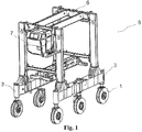
- Figure 1 shows a perspective view of a container carrier 8 such as a straddle carrier.
- a container carrier 8 as shown has a left side that comprises a front wheel close to a first end of the apparatus' frame and a rear wheel close to a second end of the apparatus' frame, and opposite to the left side a right side that has a front wheel opposite to the front wheel of the left side and a rear wheel opposite to the rear wheel of the left side.
- the wheels 1 of the container carrier 8 which usually have rubber tires are attached from their axis to the beam 3 that connects them in a way that they can be rotated in respect to a longitudinal direction, which is the direction of the line connecting a front wheel and a rear wheel.
- the carrier 8 has three wheels on each side.
- the crane or carrier 8 then comprises one vertical bar on each side that connects the horizontal bar connecting the wheels with a horizontal bar or horizontal bars 6 on top of the carrier or crane 8.
- a lifting apparatus is connected to this at least one horizontal bar 6 on top of the carrier or crane 8, which lifting apparatus is able to lift at least one container off the ground.
- a container carrier 8 usually comprises a cabin 7 for the driver.
- the illustrated container carrier 8 is a straddle carrier.
- a container carrier according to the invention can also be a shuttle carrier, sprinter carrier or transporting carrier.
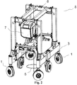
- FIG 2 is depicted a perspective view of the straddle carrier 8 of figure 1 with the wheels 1 oriented in a way to enable a carousel maneuver of the carrier 8 around its center axis.
- a vertical the center axis 5 is depicted.
- the axis 5 is the center axis of the entire carrier 8.
- the coordinate of the center axis of the crane or carrier 5 in a longitudinal direction that is usually aligned with the side beams is the middle point between the front wheel and the rear wheel. Often, the midpoint in the longitudinal direction lies between two center wheels of the vehicle. In a transverse direction, the center point is situated in the middle between the left and right side of the carrier or crane 8. In order to achieve a rotating radius that is as small as possible, the carrier 8 needs to rotate around the mentioned center axis.
- FIG 3 a schematic top view of a carousel turning movement of a carrier according to the invention is shown.
- the carrier has six wheels 1.
- the wheels are attached to the side beams 3 of the carrier.
- the front wheels and the back wheels define the smallest possible turning radius 4. It is, however, possible that the carrier structure has parts protruding outwards further than the wheels. In this case, the carrier will need more space for turning than the turning radius defined by the wheels.
- the direction of the turning motion 2 can be clockwise or counterclockwise.
- each wheel 1 of the carrier turns to a direction such that it forms a tangent to the center axis 5 of the carrier.
- the driving direction of the left side front and rear wheels is reversed while the right side front and rear wheels remain going forward.
- the left side front and rear wheels spin forward while the motion of the right side front and rear wheels is reversed.
- the operator or the control system stops the rotational motion when the container carrier has achieved the desired position.
- the rotation axis in a carousel maneuver is different from the center axis of the carrier.
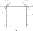
- figure 4 is shown an example where a carrier having four wheels rotates around one of its back wheels.
- both the left and the right back wheel are in a position aligned with the longitudinal axis of the carrier.
- the left front wheel is turned in a way that it forms a tangent to the center axis.
- the right wheel is turned at an angle of approximately 90 degrees.
- the carrier turns around the left back wheel.
- the positions of the front wheels are marked in dashed lines.
- the right front wheel is turned at an angle in a way that it forms a tangent to the center axis.
- the left front wheel is turned at an angle of approximately 90 degrees.
- the carrier rotates around the right back wheel.
- the carrier can rotate around the left front wheel or around the right front wheel when the wheels have been turned to respective positions.
- a skew maneuver of a carrier is shown.
- all wheels turn at the same angle to enable a motion of the carrier to the side or to a diagonal direction.
- the wheels are turned at an angle of approximately 70 degrees on the left side; consequently, the carrier will move in a direction indicated by an arrow 9.
- the wheels are turned at an angle of approximately 70 degrees on the right. Consequently, the carrier moves in a direction indicated by a dashed arrow 10.
- the wheels can be turned at any other angle supported by the turning mechanics. According to one embodiment, the wheels are turned at an angle larger than 45 degrees.
- a carrier can also have more wheels, for example up to 32.
- An apparatus includes a control system for the controlling of movement of the carrier.
- the control system comprises wheel position sensors for determining the position angles of the wheels.
- the control system includes a computer, which means a device having a processor and memory, such as a programmable logic (PLC). Inputs from the sensors are communicated to the computer, which executes a computer program based on the inputs and steers actuators such as a motor, pump or cylinder.
- PLC programmable logic
- the movement of the container carrier in the port can then be steered by a port automation system or by a user through a user interface.
- a user interface is included usually in the cabin for the operator to control the movement of the carrier.
- the user interface comprises a steering wheel and pedals; in another example, the user interfaces comprises a joystick.
- the user interface comprises a button situated inside the operator's cabin or, in case of an automated vehicle, also in another building or cabin.
- the user interface can comprise an operating panel for the user, such as a touch screen or a computer screen. This operating panel can, according to one example, have a Linux-based operating system.
- the carrier identifies a container to be transported using sensors for example by reading a bar code attached to the container.
- the automation system compares the data of the container with container location data in the system in order to determine the destination location and orientation for the container in the port area. Based on the initial location and orientation of the container and the destination location and orientation, the system calculates the path to drive and the movements of the container carrier, always taking into account obstacles and other vehicles within the port area.
- the calculated route is transmitted to the vehicle's control system in order for the route to be executed.
- the route will also include necessary turning maneuvers such as carousel maneuvers.
- the control system comprises controlling the wheel turning.
- the wheels of a carrier are turned by hydraulic cylinders.
- the control system takes in the input about the turning angle, for example given by turning a steering wheel or by a number value given, and translates it into movement of the cylinders to achieve the desired angle.
- the translation of the movement can be implemented in different ways.
- the motion of valves is controlled, which control fluid supply to the cylinders, thus resulting in motion of the cylinders.
- the steering input is measured by a sensor, and the measured value is sent to an engine control unit that controls a motor affecting a pump. The pump then is supplying fluid to the cylinder, resulting in the motion.
- the different parts of the user interface such as pedals, steering wheel and touch screen, the measurement devices, steering of the valves and the PLC are connected by a bus, such as a CAN- or DeviceNet-bus.
- the rotating or carousel maneuver according to the invention can be started. Also, a function to stop the rotating maneuver and turn the wheels back to a straight position is included. This function then, according to one example, sends signals to the valves to make the cylinders turn the wheels at the desired angle, the angle being measured by a sensor.
- the embodiments of the present invention may be implemented in software, hardware, application logic or a combination of software, hardware and application logic.
- the application logic, software or instruction set is maintained on any one of various conventional computer-readable media.
- a "computer-readable medium" may be any media or means that can contain, store, communicate, propagate or transport the instructions for use by or in connection with an instruction execution system, apparatus, or device, such as a computer.
- a computer-readable medium may comprise a computer-readable storage medium that may be any media or means that can contain or store the instructions for use by or in connection with an instruction execution system, apparatus, or device, such as a computer.
- the exemplary embodiments can store information relating to various processes described herein.
- This information can be stored in one or more memories, such as a hard disk, optical disk, magneto-optical disk, RAM, and the like.
- One or more databases can store the information used to implement the exemplary embodiments of the present inventions.
- the databases can be organized using data structures (e.g., records, tables, arrays, fields, graphs, trees, lists, and the like) included in one or more memories or storage devices listed herein.
- the processes described with respect to the exemplary embodiments can include appropriate data structures for storing data collected and/or generated by the processes of the devices and subsystems of the exemplary embodiments in one or more databases.
- All or a portion of the exemplary embodiments can be conveniently implemented using one or more general purpose processors, microprocessors, digital signal processors, micro-controllers, and the like, programmed according to the teachings of the exemplary embodiments of the present inventions, as will be appreciated by those skilled in the computer and/or software art(s).
- Appropriate software can be readily prepared by programmers of ordinary skill based on the teachings of the exemplary embodiments, as will be appreciated by those skilled in the software art.
- the exemplary embodiments can be implemented by the preparation of application-specific integrated circuits or by interconnecting an appropriate network of conventional component circuits, as will be appreciated by those skilled in the electrical art(s).
- the exemplary embodiments are not limited to any specific combination of hardware and/or software.
Landscapes
- Engineering & Computer Science (AREA)
- Mechanical Engineering (AREA)
- Steering-Linkage Mechanisms And Four-Wheel Steering (AREA)
Claims (15)
- Verfahren zum Bewegen eines Behälterträgers (8), dadurch gekennzeichnet, dass das Verfahren die folgenden Schritte umfasst:Absenken des Behälters, Bewirken, dass sich das Gewicht des Behälters und des Spreaders von den Rädern (1) löst,Drehen der Räder (1) in eine Orientierung, die für ein Rundlauf (2)- oder Verdreh (9, 10)-Manöver geeignet ist,Anheben des Behälters, undStarten eines Rundlauf (2)- oder Verdreh (9, 10)-Manövers.
- Verfahren gemäß Anspruch 1, gekennzeichnet durch Stoppen des Rundlauf (2)- oder Verdreh (9, 10)-Manövers, wenn der Behälter eine vorbestimmte Position erreicht hat.
- Verfahren gemäß Anspruch 2, gekennzeichnet durch Absenken des Behälters, Bewirken, dass sich das Gewicht des Behälters von den Rädern (1) löst, und Drehen der Räder (1) in eine entlang der Längsachse des Trägers (8) ausgerichtete Orientierung und anschließendes Anheben des Behälters.
- Verfahren gemäß Anspruch 1, gekennzeichnet durch Empfangen eines Befehls, das Rundlauf (2)- oder Verdreh (9, 10)-Manöver zu starten.
- Verfahren gemäß einem der vorangehenden Ansprüche 1-4, gekennzeichnet durch Empfangen eines Befehls zum Stoppen des Rundlauf (2)- oder Verdreh (9, 10)-Manövers und zum Drehen der Räder (1) in eine entlang der Längsachse des Trägers (8) ausgerichtete Orientierung.
- Vorrichtung zum Bewegen eines Behälterträgers (8), wobei die Bewegung des Behälterträgers (8) durch ein Port-Automatisierungssystem gesteuert wird, gekennzeichnet durch Mittel zur Durchführung von:Absenken des Behälters, Bewirken, dass sich das Gewicht des Behälters und des Spreaders von den Rädern (1) löst,Drehen der Räder (1) in eine Orientierung, die für ein Rundlauf (2)- oder Verdreh (9, 10)-Manöver geeignet ist,Anheben des Behälters, undStarten eines Rundlauf (2)- oder Verdreh (9, 10)-Manövers.
- Vorrichtung gemäß Anspruch 6,
dadurch gekennzeichnet, dass die Vorrichtung dazu ausgebildet ist, das Stoppen des Rundlauf (2)- oder Verdreh (9, 10)-Manövers durchzuführen, wenn der Behälter eine vorbestimmte Position erreicht hat. - Vorrichtung gemäß Anspruch 7, dadurch gekennzeichnet, dass die Vorrichtung dazu ausgebildet ist, das Absenken des Behälters durchzuführen und zu bewirken, dass sich das Gewicht des Behälters von den Rädern (1) löst, zum Drehen der Räder (1) in eine mit der Längsachse des Trägers (8) ausgerichtete Orientierung und anschließendes Anheben des Behälters durchzuführen.
- Vorrichtung gemäß Anspruch 6,
dadurch gekennzeichnet, dass die Vorrichtung dazu ausgebildet ist, das Empfangen eines Befehls, das Rundlauf (2)- oder Verdreh (9, 10)-Manöver zu beginnen, durchzuführen. - Vorrichtung gemäß den Ansprüchen 6-9, dadurch gekennzeichnet, dass die Vorrichtung dazu ausgebildet ist, das Empfangen eines Befehls, das Rundlauf (2)- oder Verdreh (9, 10)-Manöver zu stoppen, durchzuführen und die Räder (1) in eine mit der Längsachse des Trägers (8) ausgerichtete Orientierung zu drehen.
- Computerprogrammprodukt zum Bewegen eines Behälterträgers (8), umfassend ein Computer-lesbares Medium, das Computerprogrammcode trägt, dadurch gekennzeichnet, dass der Computerprogrammcode Folgendes umfasst: Code zum Absenken des Behälters, Bewirken, dass sich das Gewicht des Behälters und des Spreaders von den Rädern (1) löst,Code zum Drehen der Räder (1) in eine Orientierung, die für ein Rundlauf (2)- oder Verdreh (9, 10)-Manöver geeignet ist,Code zum Anheben des Behälters,Code zum Starten eines Rundlauf (2)- oder Verdreh (9, 10)-Manövers.
- Computerprogrammprodukt gemäß Anspruch 11, dadurch gekennzeichnet, dass es Code zum Stoppen des Rundlauf (2)- oder Verdreh (9, 10)-Manövers, wenn der Behälter die gewünschte Position erreicht hat, umfasst.
- Computerprogrammprodukt gemäß Anspruch 11, dadurch gekennzeichnet, dass es Code zum Absenken des Behälters, Bewirken, dass sich das Gewicht des Behälters von den Rädern (1) löst, und zum Drehen der Räder (1) und anschließenden Anheben des Behälters umfasst.
- Computerprogrammprodukt gemäß Anspruch 11, dadurch gekennzeichnet, dass es Code zum Empfangen eines Befehls, das Rundlauf (2)- oder Verdreh (9, 10)-Manöver zu beginnen, umfasst.
- Computerprogrammprodukt gemäß den Ansprüchen 11-14, dadurch gekennzeichnet, dass es Code zum Empfangen eines Befehls, das Rundlauf (2)- oder Verdreh (9, 10)-Manöver zu stoppen und die Räder (1) in eine mit der Längsachse des Trägers (8) ausgerichtete Orientierung zu drehen, umfasst.
Applications Claiming Priority (1)
| Application Number | Priority Date | Filing Date | Title |
|---|---|---|---|
| PCT/FI2012/051224 WO2014091057A1 (en) | 2012-12-11 | 2012-12-11 | Method, apparatus and computer program for moving a container carrier |
Publications (3)
| Publication Number | Publication Date |
|---|---|
| EP2931647A1 EP2931647A1 (de) | 2015-10-21 |
| EP2931647A4 EP2931647A4 (de) | 2016-08-03 |
| EP2931647B1 true EP2931647B1 (de) | 2018-08-01 |
Family
ID=50933794
Family Applications (1)
| Application Number | Title | Priority Date | Filing Date |
|---|---|---|---|
| EP12889943.2A Active EP2931647B1 (de) | 2012-12-11 | 2012-12-11 | Verfahren, vorrichtung und computerprogramm zum bewegen eines behälterträgers |
Country Status (3)
| Country | Link |
|---|---|
| US (1) | US9701518B2 (de) |
| EP (1) | EP2931647B1 (de) |
| WO (1) | WO2014091057A1 (de) |
Families Citing this family (16)
| Publication number | Priority date | Publication date | Assignee | Title |
|---|---|---|---|---|
| CA167756S (en) * | 2015-10-07 | 2018-01-02 | Starship Tech Oü | Delivery robot |
| DE102015118535A1 (de) | 2015-10-29 | 2017-05-04 | Terex MHPS IP Management GmbH | Schwerlaststapler |
| DE102015119193A1 (de) * | 2015-11-07 | 2017-05-11 | Terex MHPS IP Management GmbH | Batteriemodul für einen Fahrantrieb und Transportfahrzeug hiermit |
| DE102015121846B4 (de) | 2015-12-15 | 2017-07-27 | Terex Mhps Gmbh | Transportfahrzeug für Container |
| DE102015121804B4 (de) | 2015-12-15 | 2017-07-27 | Terex Mhps Gmbh | Transportfahrzeug für Container |
| WO2018037429A1 (en) * | 2016-08-26 | 2018-03-01 | Cimolai Technology Spa | Method and system for steering a gantry crane |
| US12337875B2 (en) * | 2017-03-19 | 2025-06-24 | Gal Zuckerman | Systems and methods for autonomously delivering packages using a plurality of package containers |
| US11599845B2 (en) * | 2017-03-19 | 2023-03-07 | Gal Zuckerman | Systems and methods for autonomously delivering consumer items in disposable packages |
| US10384871B2 (en) * | 2017-03-19 | 2019-08-20 | Gal Zuckerman | Next generation on-road vehicles and related methods of usage |
| US11046230B2 (en) * | 2017-03-19 | 2021-06-29 | Gal Zuckerman | Systems and methods for autonomously altering shape and functionality of on-road vehicles |
| USD821265S1 (en) | 2017-03-23 | 2018-06-26 | Starship Technologies Oü | Vehicle |
| WO2018215581A1 (en) | 2017-05-26 | 2018-11-29 | Starship Technologies Oü | A battery and a system for swapping and/or charging a battery of a mobile robot |
| EP3659104B1 (de) | 2017-07-28 | 2024-01-17 | Starship Technologies OÜ | Vorrichtung und system zur sicheren paketbereitstellung durch einen mobilen roboter |
| AT520763B1 (de) * | 2017-12-21 | 2022-09-15 | Hans Kuenz Gmbh | Kransteuerung |
| FI127956B (en) * | 2018-01-17 | 2019-06-14 | Cargotec Finland Oy | Service platform, boundary truck and procedure |
| GB201916858D0 (en) | 2019-11-19 | 2020-01-01 | Belanger Marco | Lifting rig for moving heavy objects on rooftops |
Citations (1)
| Publication number | Priority date | Publication date | Assignee | Title |
|---|---|---|---|---|
| US7350840B2 (en) * | 2002-09-13 | 2008-04-01 | Gottwald Port Technology Gmbh | Lifting device for containers |
Family Cites Families (10)
| Publication number | Priority date | Publication date | Assignee | Title |
|---|---|---|---|---|
| US5180070A (en) * | 1991-05-30 | 1993-01-19 | Shuttelift, Inc. | Directional control system for a gantry type crane |
| FI101957B (fi) * | 1994-07-15 | 1998-09-30 | Kci Kone Cranes Internat Oy | Nosturi |
| US6206127B1 (en) * | 1998-02-27 | 2001-03-27 | Mi-Jack Products | Lead wheel steering system for a gantry crane |
| JPH11310386A (ja) | 1998-04-27 | 1999-11-09 | Kitagawa Iron Works Co Ltd | 橋形クレーンの走行方向転換装置 |
| CN2517723Y (zh) | 2001-12-26 | 2002-10-23 | 上海振华港口机械股份有限公司 | 轮胎式龙门集装箱起重机大车行走车轮液压顶升转向机构 |
| US7252299B2 (en) * | 2005-02-15 | 2007-08-07 | Marine Travelift, Inc. | Steering system for crane |
| ITBO20050487A1 (it) * | 2005-07-20 | 2007-01-21 | C V S S P A | Apparecchiatura per il trasporto di un carico |
| CN1872653A (zh) | 2006-06-29 | 2006-12-06 | 上海振华港口机械(集团)股份有限公司 | 轮胎式集装箱龙门起重机的顶升转向装置 |
| IT1392130B1 (it) * | 2008-11-03 | 2012-02-22 | Eden Technology Srl | Dispositivo di sterzatura automatica per carrelli semoventi di sollevamento e trasporto manufatti. |
| CN102229402B (zh) | 2011-05-23 | 2013-06-19 | 三一集团有限公司 | 一种轮胎式集装箱门式起重机及其转向装置 |
-
2012
- 2012-12-11 EP EP12889943.2A patent/EP2931647B1/de active Active
- 2012-12-11 WO PCT/FI2012/051224 patent/WO2014091057A1/en not_active Ceased
- 2012-12-11 US US14/647,182 patent/US9701518B2/en active Active
Patent Citations (1)
| Publication number | Priority date | Publication date | Assignee | Title |
|---|---|---|---|---|
| US7350840B2 (en) * | 2002-09-13 | 2008-04-01 | Gottwald Port Technology Gmbh | Lifting device for containers |
Also Published As
| Publication number | Publication date |
|---|---|
| EP2931647A1 (de) | 2015-10-21 |
| EP2931647A4 (de) | 2016-08-03 |
| WO2014091057A1 (en) | 2014-06-19 |
| US9701518B2 (en) | 2017-07-11 |
| US20150307329A1 (en) | 2015-10-29 |
Similar Documents
| Publication | Publication Date | Title |
|---|---|---|
| EP2931647B1 (de) | Verfahren, vorrichtung und computerprogramm zum bewegen eines behälterträgers | |
| CN104428192B (zh) | 用于车辆的转向系统以及车辆的转向方法 | |
| US9393996B2 (en) | Reverse drive assist for long wheelbase dual axle trailers | |
| US6206127B1 (en) | Lead wheel steering system for a gantry crane | |
| CN103803457B (zh) | 用于四轮平衡重式叉车平衡控制系统的电控系统 | |
| WO2013038998A1 (ja) | 自走ロボットおよび自走台車 | |
| CN103863390A (zh) | 四轮平衡重式叉车平衡控制系统 | |
| KR20240010492A (ko) | 객체를 운반하는 모듈형 로봇 시스템 및 방법 | |
| JP2001347975A (ja) | 走行装置及び該走行装置を備えたクレーン | |
| JPH0775988B2 (ja) | 走行車両のステアリング装置 | |
| JPH05116643A (ja) | リーチ型フオークリフト | |
| JP5403968B2 (ja) | 編成搬送台車設備 | |
| JP7439724B2 (ja) | 無人産業車両 | |
| EP3875420B1 (de) | Transportroboter | |
| JPH0592769A (ja) | リーチ型フオークリフトの走行操作方法 | |
| JP5403967B2 (ja) | 編成搬送台車設備 | |
| JP2003034262A (ja) | 走行台車 | |
| US20050154504A1 (en) | Vehicles and control systems thereof with adjustable steering axes | |
| JP2000185893A (ja) | 相互連携車両の走行制御装置 | |
| CN112209297A (zh) | 一种四向行驶的步行式侧面堆垛车 | |
| JP7774532B2 (ja) | 移動制御装置、移動制御システム、移動制御方法、及びプログラム | |
| EP4159592A1 (de) | Lenkungssteuerungsvorrichtung für arbeitsfahrzeug | |
| US20200001918A1 (en) | Method and system for steering wheel assemblies for cranes | |
| JPH05178232A (ja) | リーチ型フォークリフトの制御方法 | |
| JP5312226B2 (ja) | 編成搬送台車設備 |
Legal Events
| Date | Code | Title | Description |
|---|---|---|---|
| PUAI | Public reference made under article 153(3) epc to a published international application that has entered the european phase |
Free format text: ORIGINAL CODE: 0009012 |
|
| 17P | Request for examination filed |
Effective date: 20150708 |
|
| AK | Designated contracting states |
Kind code of ref document: A1 Designated state(s): AL AT BE BG CH CY CZ DE DK EE ES FI FR GB GR HR HU IE IS IT LI LT LU LV MC MK MT NL NO PL PT RO RS SE SI SK SM TR |
|
| AX | Request for extension of the european patent |
Extension state: BA ME |
|
| DAX | Request for extension of the european patent (deleted) | ||
| REG | Reference to a national code |
Ref country code: DE Ref legal event code: R079 Ref document number: 602012049298 Country of ref document: DE Free format text: PREVIOUS MAIN CLASS: B66C0009000000 Ipc: B66C0019000000 |
|
| A4 | Supplementary search report drawn up and despatched |
Effective date: 20160705 |
|
| RIC1 | Information provided on ipc code assigned before grant |
Ipc: B66C 19/00 20060101AFI20160628BHEP Ipc: B66C 9/04 20060101ALI20160628BHEP |
|
| 17Q | First examination report despatched |
Effective date: 20170530 |
|
| GRAP | Despatch of communication of intention to grant a patent |
Free format text: ORIGINAL CODE: EPIDOSNIGR1 |
|
| INTG | Intention to grant announced |
Effective date: 20180321 |
|
| GRAS | Grant fee paid |
Free format text: ORIGINAL CODE: EPIDOSNIGR3 |
|
| GRAA | (expected) grant |
Free format text: ORIGINAL CODE: 0009210 |
|
| AK | Designated contracting states |
Kind code of ref document: B1 Designated state(s): AL AT BE BG CH CY CZ DE DK EE ES FI FR GB GR HR HU IE IS IT LI LT LU LV MC MK MT NL NO PL PT RO RS SE SI SK SM TR |
|
| REG | Reference to a national code |
Ref country code: GB Ref legal event code: FG4D |
|
| REG | Reference to a national code |
Ref country code: CH Ref legal event code: EP Ref country code: AT Ref legal event code: REF Ref document number: 1024043 Country of ref document: AT Kind code of ref document: T Effective date: 20180815 |
|
| REG | Reference to a national code |
Ref country code: IE Ref legal event code: FG4D |
|
| REG | Reference to a national code |
Ref country code: DE Ref legal event code: R096 Ref document number: 602012049298 Country of ref document: DE |
|
| REG | Reference to a national code |
Ref country code: NL Ref legal event code: MP Effective date: 20180801 |
|
| REG | Reference to a national code |
Ref country code: LT Ref legal event code: MG4D |
|
| REG | Reference to a national code |
Ref country code: AT Ref legal event code: MK05 Ref document number: 1024043 Country of ref document: AT Kind code of ref document: T Effective date: 20180801 |
|
| PG25 | Lapsed in a contracting state [announced via postgrant information from national office to epo] |
Ref country code: PL Free format text: LAPSE BECAUSE OF FAILURE TO SUBMIT A TRANSLATION OF THE DESCRIPTION OR TO PAY THE FEE WITHIN THE PRESCRIBED TIME-LIMIT Effective date: 20180801 Ref country code: RS Free format text: LAPSE BECAUSE OF FAILURE TO SUBMIT A TRANSLATION OF THE DESCRIPTION OR TO PAY THE FEE WITHIN THE PRESCRIBED TIME-LIMIT Effective date: 20180801 Ref country code: LT Free format text: LAPSE BECAUSE OF FAILURE TO SUBMIT A TRANSLATION OF THE DESCRIPTION OR TO PAY THE FEE WITHIN THE PRESCRIBED TIME-LIMIT Effective date: 20180801 Ref country code: AT Free format text: LAPSE BECAUSE OF FAILURE TO SUBMIT A TRANSLATION OF THE DESCRIPTION OR TO PAY THE FEE WITHIN THE PRESCRIBED TIME-LIMIT Effective date: 20180801 Ref country code: IS Free format text: LAPSE BECAUSE OF FAILURE TO SUBMIT A TRANSLATION OF THE DESCRIPTION OR TO PAY THE FEE WITHIN THE PRESCRIBED TIME-LIMIT Effective date: 20181201 Ref country code: NL Free format text: LAPSE BECAUSE OF FAILURE TO SUBMIT A TRANSLATION OF THE DESCRIPTION OR TO PAY THE FEE WITHIN THE PRESCRIBED TIME-LIMIT Effective date: 20180801 Ref country code: BG Free format text: LAPSE BECAUSE OF FAILURE TO SUBMIT A TRANSLATION OF THE DESCRIPTION OR TO PAY THE FEE WITHIN THE PRESCRIBED TIME-LIMIT Effective date: 20181101 Ref country code: NO Free format text: LAPSE BECAUSE OF FAILURE TO SUBMIT A TRANSLATION OF THE DESCRIPTION OR TO PAY THE FEE WITHIN THE PRESCRIBED TIME-LIMIT Effective date: 20181101 Ref country code: GR Free format text: LAPSE BECAUSE OF FAILURE TO SUBMIT A TRANSLATION OF THE DESCRIPTION OR TO PAY THE FEE WITHIN THE PRESCRIBED TIME-LIMIT Effective date: 20181102 Ref country code: FI Free format text: LAPSE BECAUSE OF FAILURE TO SUBMIT A TRANSLATION OF THE DESCRIPTION OR TO PAY THE FEE WITHIN THE PRESCRIBED TIME-LIMIT Effective date: 20180801 Ref country code: SE Free format text: LAPSE BECAUSE OF FAILURE TO SUBMIT A TRANSLATION OF THE DESCRIPTION OR TO PAY THE FEE WITHIN THE PRESCRIBED TIME-LIMIT Effective date: 20180801 |
|
| PG25 | Lapsed in a contracting state [announced via postgrant information from national office to epo] |
Ref country code: AL Free format text: LAPSE BECAUSE OF FAILURE TO SUBMIT A TRANSLATION OF THE DESCRIPTION OR TO PAY THE FEE WITHIN THE PRESCRIBED TIME-LIMIT Effective date: 20180801 Ref country code: LV Free format text: LAPSE BECAUSE OF FAILURE TO SUBMIT A TRANSLATION OF THE DESCRIPTION OR TO PAY THE FEE WITHIN THE PRESCRIBED TIME-LIMIT Effective date: 20180801 Ref country code: HR Free format text: LAPSE BECAUSE OF FAILURE TO SUBMIT A TRANSLATION OF THE DESCRIPTION OR TO PAY THE FEE WITHIN THE PRESCRIBED TIME-LIMIT Effective date: 20180801 |
|
| PG25 | Lapsed in a contracting state [announced via postgrant information from national office to epo] |
Ref country code: IT Free format text: LAPSE BECAUSE OF FAILURE TO SUBMIT A TRANSLATION OF THE DESCRIPTION OR TO PAY THE FEE WITHIN THE PRESCRIBED TIME-LIMIT Effective date: 20180801 Ref country code: EE Free format text: LAPSE BECAUSE OF FAILURE TO SUBMIT A TRANSLATION OF THE DESCRIPTION OR TO PAY THE FEE WITHIN THE PRESCRIBED TIME-LIMIT Effective date: 20180801 Ref country code: ES Free format text: LAPSE BECAUSE OF FAILURE TO SUBMIT A TRANSLATION OF THE DESCRIPTION OR TO PAY THE FEE WITHIN THE PRESCRIBED TIME-LIMIT Effective date: 20180801 Ref country code: RO Free format text: LAPSE BECAUSE OF FAILURE TO SUBMIT A TRANSLATION OF THE DESCRIPTION OR TO PAY THE FEE WITHIN THE PRESCRIBED TIME-LIMIT Effective date: 20180801 Ref country code: CZ Free format text: LAPSE BECAUSE OF FAILURE TO SUBMIT A TRANSLATION OF THE DESCRIPTION OR TO PAY THE FEE WITHIN THE PRESCRIBED TIME-LIMIT Effective date: 20180801 |
|
| REG | Reference to a national code |
Ref country code: DE Ref legal event code: R097 Ref document number: 602012049298 Country of ref document: DE |
|
| PG25 | Lapsed in a contracting state [announced via postgrant information from national office to epo] |
Ref country code: SM Free format text: LAPSE BECAUSE OF FAILURE TO SUBMIT A TRANSLATION OF THE DESCRIPTION OR TO PAY THE FEE WITHIN THE PRESCRIBED TIME-LIMIT Effective date: 20180801 Ref country code: DK Free format text: LAPSE BECAUSE OF FAILURE TO SUBMIT A TRANSLATION OF THE DESCRIPTION OR TO PAY THE FEE WITHIN THE PRESCRIBED TIME-LIMIT Effective date: 20180801 Ref country code: SK Free format text: LAPSE BECAUSE OF FAILURE TO SUBMIT A TRANSLATION OF THE DESCRIPTION OR TO PAY THE FEE WITHIN THE PRESCRIBED TIME-LIMIT Effective date: 20180801 |
|
| PLBE | No opposition filed within time limit |
Free format text: ORIGINAL CODE: 0009261 |
|
| STAA | Information on the status of an ep patent application or granted ep patent |
Free format text: STATUS: NO OPPOSITION FILED WITHIN TIME LIMIT |
|
| 26N | No opposition filed |
Effective date: 20190503 |
|
| REG | Reference to a national code |
Ref country code: CH Ref legal event code: PL |
|
| PG25 | Lapsed in a contracting state [announced via postgrant information from national office to epo] |
Ref country code: LU Free format text: LAPSE BECAUSE OF NON-PAYMENT OF DUE FEES Effective date: 20181211 Ref country code: MC Free format text: LAPSE BECAUSE OF FAILURE TO SUBMIT A TRANSLATION OF THE DESCRIPTION OR TO PAY THE FEE WITHIN THE PRESCRIBED TIME-LIMIT Effective date: 20180801 Ref country code: SI Free format text: LAPSE BECAUSE OF FAILURE TO SUBMIT A TRANSLATION OF THE DESCRIPTION OR TO PAY THE FEE WITHIN THE PRESCRIBED TIME-LIMIT Effective date: 20180801 |
|
| REG | Reference to a national code |
Ref country code: IE Ref legal event code: MM4A |
|
| PG25 | Lapsed in a contracting state [announced via postgrant information from national office to epo] |
Ref country code: FR Free format text: LAPSE BECAUSE OF NON-PAYMENT OF DUE FEES Effective date: 20181231 Ref country code: IE Free format text: LAPSE BECAUSE OF NON-PAYMENT OF DUE FEES Effective date: 20181211 |
|
| PG25 | Lapsed in a contracting state [announced via postgrant information from national office to epo] |
Ref country code: LI Free format text: LAPSE BECAUSE OF NON-PAYMENT OF DUE FEES Effective date: 20181231 Ref country code: CH Free format text: LAPSE BECAUSE OF NON-PAYMENT OF DUE FEES Effective date: 20181231 |
|
| PG25 | Lapsed in a contracting state [announced via postgrant information from national office to epo] |
Ref country code: MT Free format text: LAPSE BECAUSE OF NON-PAYMENT OF DUE FEES Effective date: 20181211 |
|
| PG25 | Lapsed in a contracting state [announced via postgrant information from national office to epo] |
Ref country code: TR Free format text: LAPSE BECAUSE OF FAILURE TO SUBMIT A TRANSLATION OF THE DESCRIPTION OR TO PAY THE FEE WITHIN THE PRESCRIBED TIME-LIMIT Effective date: 20180801 |
|
| PG25 | Lapsed in a contracting state [announced via postgrant information from national office to epo] |
Ref country code: PT Free format text: LAPSE BECAUSE OF FAILURE TO SUBMIT A TRANSLATION OF THE DESCRIPTION OR TO PAY THE FEE WITHIN THE PRESCRIBED TIME-LIMIT Effective date: 20180801 |
|
| PG25 | Lapsed in a contracting state [announced via postgrant information from national office to epo] |
Ref country code: HU Free format text: LAPSE BECAUSE OF FAILURE TO SUBMIT A TRANSLATION OF THE DESCRIPTION OR TO PAY THE FEE WITHIN THE PRESCRIBED TIME-LIMIT; INVALID AB INITIO Effective date: 20121211 Ref country code: CY Free format text: LAPSE BECAUSE OF FAILURE TO SUBMIT A TRANSLATION OF THE DESCRIPTION OR TO PAY THE FEE WITHIN THE PRESCRIBED TIME-LIMIT Effective date: 20180801 Ref country code: MK Free format text: LAPSE BECAUSE OF NON-PAYMENT OF DUE FEES Effective date: 20180801 |
|
| REG | Reference to a national code |
Ref country code: DE Ref legal event code: R081 Ref document number: 602012049298 Country of ref document: DE Owner name: KALMAR FINLAND OY, FI Free format text: FORMER OWNER: CARGOTEC FINLAND OY,, TAMPERE, FI |
|
| PGFP | Annual fee paid to national office [announced via postgrant information from national office to epo] |
Ref country code: GB Payment date: 20251219 Year of fee payment: 14 |
|
| PGFP | Annual fee paid to national office [announced via postgrant information from national office to epo] |
Ref country code: BE Payment date: 20251219 Year of fee payment: 14 |
|
| PGFP | Annual fee paid to national office [announced via postgrant information from national office to epo] |
Ref country code: DE Payment date: 20251230 Year of fee payment: 14 |