EP2931647B1 - Method, apparatus and computer program for moving a container carrier - Google Patents
Method, apparatus and computer program for moving a container carrier Download PDFInfo
- Publication number
- EP2931647B1 EP2931647B1 EP12889943.2A EP12889943A EP2931647B1 EP 2931647 B1 EP2931647 B1 EP 2931647B1 EP 12889943 A EP12889943 A EP 12889943A EP 2931647 B1 EP2931647 B1 EP 2931647B1
- Authority
- EP
- European Patent Office
- Prior art keywords
- container
- wheels
- carrier
- maneuver
- carousel
- Prior art date
- Legal status (The legal status is an assumption and is not a legal conclusion. Google has not performed a legal analysis and makes no representation as to the accuracy of the status listed.)
- Active
Links
- 238000000034 method Methods 0.000 title claims description 24
- 238000004590 computer program Methods 0.000 title claims description 21
- 239000000969 carrier Substances 0.000 description 13
- 230000008569 process Effects 0.000 description 6
- 230000006870 function Effects 0.000 description 4
- 230000015654 memory Effects 0.000 description 3
- 239000012530 fluid Substances 0.000 description 2
- 230000009471 action Effects 0.000 description 1
- 238000003491 array Methods 0.000 description 1
- 239000010426 asphalt Substances 0.000 description 1
- 230000008859 change Effects 0.000 description 1
- 230000001419 dependent effect Effects 0.000 description 1
- 238000005516 engineering process Methods 0.000 description 1
- 239000000463 material Substances 0.000 description 1
- 238000005259 measurement Methods 0.000 description 1
- 230000007246 mechanism Effects 0.000 description 1
- 230000003287 optical effect Effects 0.000 description 1
- 230000004044 response Effects 0.000 description 1
Images


Classifications
-
- B—PERFORMING OPERATIONS; TRANSPORTING
- B66—HOISTING; LIFTING; HAULING
- B66C—CRANES; LOAD-ENGAGING ELEMENTS OR DEVICES FOR CRANES, CAPSTANS, WINCHES, OR TACKLES
- B66C9/00—Travelling gear incorporated in or fitted to trolleys or cranes
- B66C9/04—Travelling gear incorporated in or fitted to trolleys or cranes to facilitate negotiation of curves
-
- B—PERFORMING OPERATIONS; TRANSPORTING
- B66—HOISTING; LIFTING; HAULING
- B66C—CRANES; LOAD-ENGAGING ELEMENTS OR DEVICES FOR CRANES, CAPSTANS, WINCHES, OR TACKLES
- B66C19/00—Cranes comprising trolleys or crabs running on fixed or movable bridges or gantries
- B66C19/005—Straddle carriers
-
- B—PERFORMING OPERATIONS; TRANSPORTING
- B66—HOISTING; LIFTING; HAULING
- B66C—CRANES; LOAD-ENGAGING ELEMENTS OR DEVICES FOR CRANES, CAPSTANS, WINCHES, OR TACKLES
- B66C19/00—Cranes comprising trolleys or crabs running on fixed or movable bridges or gantries
- B66C19/007—Cranes comprising trolleys or crabs running on fixed or movable bridges or gantries for containers
Definitions
- the invention relates to container carriers in ports and terminals. More specifically, the invention relates to a method, apparatus and computer program for moving a rubber-tired container carrier.
- Shuttle carriers, straddle carriers, sprinter carriers, runner carriers and transporting carriers are used in ports for moving containers between port cranes and a storage area.
- Carriers move freely while carrying the container in the cargo area; thus, they need to be able to move flexibly also in areas of little space. Carriers can move in a rotational movement around a rotation axis or in a skew movement in a diagonal or straight direction.
- a method of turning a carrier such as a straddle carrier or transporting carrier around its own center point has been introduced.
- This method a so-called carousel maneuver
- the container can be turned at a desired angle.
- One idea of the method is to turn the front wheels and the rear wheels at an angle enabling a turn around the center axis of the vehicle.
- the driving direction of the left side front and rear wheels is reversed while the right side front and rear wheels remain going forward.
- the left side front and rear wheels spin forward while the motion of the right side front and rear wheels is reversed.
- the carousel maneuver is for example mentioned in US20110108347 .
- a loaded container can weigh between 20 and 40 tons. This puts an enormous stress on the turning mechanism of the wheels of the carrier and makes the turning of the wheels more difficult. A great force is needed to turn the wheels while the carrier is carrying the container. Turning the wheels while the container is being carried also increases wear of the tires resulting in the frequent need to change the tires. Additionally, carrier's wheels are often turned on the same spot of the cargo area, resulting in wear of the ground surface on the spot.
- EP1873112 a specialized equipment called a rubber-tyred gantry crane is disclosed having means such as hydraulic jacks for lifting the crane of the ground and then turning the wheels in the air to arrive at a desired orientation without increasing the wear of the tires.
- a similar technique is used for a similar crane in JPH11310386 .
- a gantry crane able to perform crab and carousel steering maneuvers is disclosed.
- US7350840 a lifting device for containers is disclosed.
- the container handling equipment is used for transport of containers within the container yard and container port, the container being lifted during the transport.
- the aim of this invention is to facilitate the process of maneuvering a container carrier, thus resulting in less wear of the carrier's components and the ground surface.
- a purpose of the invention is to facilitate the moving of a container carrying apparatus, such as a carrier.
- a method for moving a container carrier comprising: lowering the container, causing to disengage the weight of the container off the wheels, turning the wheels to an orientation suitable for a carousel or skew maneuver, lifting the container, and starting a carousel or skew maneuver.
- the weight of the spreader carrying the container disengages off the wheels. This again reduces the strain on the wheels, steering mechanics and the ground.
- the method comprises stopping the carousel or skew maneuver when the container has been turned at a predetermined angle.
- a predetermined angle is an angle that has been determined beforehand, for example by a user through a user interface, by turning a steering wheel or by entering a value, or that has been calculated by the port or crane automation system.
- the method comprises lowering the container, causing to disengage the weight of the container off the wheels, and turning the wheels to an orientation aligned with the longitudinal axis of the carrier and subsequently lifting the container again so that the carrier is ready to continue movement.
- the method comprises receiving a command to begin the carousel or skew maneuver.
- the command to initiate the maneuver can be sent from a user interface in response to the user action or it may be sent from the crane or port automation system.
- the method comprises receiving a command to stop the carousel or skew maneuver and to turn the wheels to an orientation aligned with the longitudinal axis of the carrier.
- the angle can deviate from the longitudinal axis to some extent. It is, however, important that all wheels deviate in the same direction.
- independent claim 6 there is disclosed an apparatus for moving a container carrier, wherein the movement of the container carrier is steered by a port automation system, the apparatus being arranged to perform at least: lowering the container, causing to disengage the weight of the container off the wheels, turning the wheels to an orientation suitable for a carousel or skew maneuver, lifting the container, starting a carousel or skew maneuver.
- One embodiment of the invention discloses an apparatus for moving a container carrier, wherein the movement of the container carrier is steered by a port automation system,, characterized by means for performing: lowering the container, causing to disengage the weight of the container off the wheels, turning the wheels to an orientation suitable for a carousel or skew maneuver, lifting the container, starting a carousel or skew maneuver.
- the apparatus is arranged to perform: stopping the carousel or skew maneuver when the container has been turned at a predetermined angle.
- the apparatus is arranged to perform: lowering the container, causing to disengage the weight of the container off the wheels, and turning the wheels to an orientation aligned with the longitudinal axis of the carrier and subsequently lifting the container again so that the carrier is ready to continue movement.
- the apparatus is arranged to perform: receiving a command to begin the carousel or skew maneuver.
- the apparatus is arranged to perform: receiving a command to stop the carousel or skew maneuver and to turn the wheels to an orientation aligned with the longitudinal axis of the carrier.
- a computer program product for turning a container carrier comprising a computer-readable medium bearing computer program code, the computer program code comprising: code for lowering the container, causing to disengage the weight of the container off the wheels, code for turning the wheels to an orientation suitable for a carousel or skew maneuver, code for lifting the container, code for starting a carousel or skew maneuver.
- the computer program product comprises code for stopping the carousel or skew maneuver when the container has been turned at a predetermined angle.
- the computer program product comprises code for lowering the container, causing to disengage the weight of the container off the wheels, and for turning the wheels and subsequently lifting the container again so that the carrier is ready to continue movement.
- the computer program product comprises code for receiving a command to begin the carousel or skew maneuver.
- the computer program product comprises code for receiving a command to stop the carousel or skew maneuver and to turn the wheels to an orientation aligned with the longitudinal axis of the carrier.
- the invention improves the problems of the container carrier moving process. Because the weight of the container does not rest on the wheels in the wheel turning process, it is easier to turn the wheels. This results in less stress on the wheel turning mechanics, less wear of the tires and less wear of the ground material, for example asphalt surface.
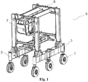
- Figure 1 shows a perspective view of a container carrier 8 such as a straddle carrier.
- a container carrier 8 as shown has a left side that comprises a front wheel close to a first end of the apparatus' frame and a rear wheel close to a second end of the apparatus' frame, and opposite to the left side a right side that has a front wheel opposite to the front wheel of the left side and a rear wheel opposite to the rear wheel of the left side.
- the wheels 1 of the container carrier 8 which usually have rubber tires are attached from their axis to the beam 3 that connects them in a way that they can be rotated in respect to a longitudinal direction, which is the direction of the line connecting a front wheel and a rear wheel.
- the carrier 8 has three wheels on each side.
- the crane or carrier 8 then comprises one vertical bar on each side that connects the horizontal bar connecting the wheels with a horizontal bar or horizontal bars 6 on top of the carrier or crane 8.
- a lifting apparatus is connected to this at least one horizontal bar 6 on top of the carrier or crane 8, which lifting apparatus is able to lift at least one container off the ground.
- a container carrier 8 usually comprises a cabin 7 for the driver.
- the illustrated container carrier 8 is a straddle carrier.
- a container carrier according to the invention can also be a shuttle carrier, sprinter carrier or transporting carrier.
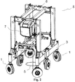
- FIG 2 is depicted a perspective view of the straddle carrier 8 of figure 1 with the wheels 1 oriented in a way to enable a carousel maneuver of the carrier 8 around its center axis.
- a vertical the center axis 5 is depicted.
- the axis 5 is the center axis of the entire carrier 8.
- the coordinate of the center axis of the crane or carrier 5 in a longitudinal direction that is usually aligned with the side beams is the middle point between the front wheel and the rear wheel. Often, the midpoint in the longitudinal direction lies between two center wheels of the vehicle. In a transverse direction, the center point is situated in the middle between the left and right side of the carrier or crane 8. In order to achieve a rotating radius that is as small as possible, the carrier 8 needs to rotate around the mentioned center axis.
- FIG 3 a schematic top view of a carousel turning movement of a carrier according to the invention is shown.
- the carrier has six wheels 1.
- the wheels are attached to the side beams 3 of the carrier.
- the front wheels and the back wheels define the smallest possible turning radius 4. It is, however, possible that the carrier structure has parts protruding outwards further than the wheels. In this case, the carrier will need more space for turning than the turning radius defined by the wheels.
- the direction of the turning motion 2 can be clockwise or counterclockwise.
- each wheel 1 of the carrier turns to a direction such that it forms a tangent to the center axis 5 of the carrier.
- the driving direction of the left side front and rear wheels is reversed while the right side front and rear wheels remain going forward.
- the left side front and rear wheels spin forward while the motion of the right side front and rear wheels is reversed.
- the operator or the control system stops the rotational motion when the container carrier has achieved the desired position.
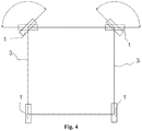
- the rotation axis in a carousel maneuver is different from the center axis of the carrier.
- figure 4 is shown an example where a carrier having four wheels rotates around one of its back wheels.
- both the left and the right back wheel are in a position aligned with the longitudinal axis of the carrier.
- the left front wheel is turned in a way that it forms a tangent to the center axis.
- the right wheel is turned at an angle of approximately 90 degrees.
- the carrier turns around the left back wheel.
- the positions of the front wheels are marked in dashed lines.
- the right front wheel is turned at an angle in a way that it forms a tangent to the center axis.
- the left front wheel is turned at an angle of approximately 90 degrees.
- the carrier rotates around the right back wheel.
- the carrier can rotate around the left front wheel or around the right front wheel when the wheels have been turned to respective positions.
- a skew maneuver of a carrier is shown.
- all wheels turn at the same angle to enable a motion of the carrier to the side or to a diagonal direction.
- the wheels are turned at an angle of approximately 70 degrees on the left side; consequently, the carrier will move in a direction indicated by an arrow 9.
- the wheels are turned at an angle of approximately 70 degrees on the right. Consequently, the carrier moves in a direction indicated by a dashed arrow 10.
- the wheels can be turned at any other angle supported by the turning mechanics. According to one embodiment, the wheels are turned at an angle larger than 45 degrees.
- a carrier can also have more wheels, for example up to 32.
- An apparatus includes a control system for the controlling of movement of the carrier.
- the control system comprises wheel position sensors for determining the position angles of the wheels.
- the control system includes a computer, which means a device having a processor and memory, such as a programmable logic (PLC). Inputs from the sensors are communicated to the computer, which executes a computer program based on the inputs and steers actuators such as a motor, pump or cylinder.
- PLC programmable logic
- the movement of the container carrier in the port can then be steered by a port automation system or by a user through a user interface.
- a user interface is included usually in the cabin for the operator to control the movement of the carrier.
- the user interface comprises a steering wheel and pedals; in another example, the user interfaces comprises a joystick.
- the user interface comprises a button situated inside the operator's cabin or, in case of an automated vehicle, also in another building or cabin.
- the user interface can comprise an operating panel for the user, such as a touch screen or a computer screen. This operating panel can, according to one example, have a Linux-based operating system.
- the carrier identifies a container to be transported using sensors for example by reading a bar code attached to the container.
- the automation system compares the data of the container with container location data in the system in order to determine the destination location and orientation for the container in the port area. Based on the initial location and orientation of the container and the destination location and orientation, the system calculates the path to drive and the movements of the container carrier, always taking into account obstacles and other vehicles within the port area.
- the calculated route is transmitted to the vehicle's control system in order for the route to be executed.
- the route will also include necessary turning maneuvers such as carousel maneuvers.
- the control system comprises controlling the wheel turning.
- the wheels of a carrier are turned by hydraulic cylinders.
- the control system takes in the input about the turning angle, for example given by turning a steering wheel or by a number value given, and translates it into movement of the cylinders to achieve the desired angle.
- the translation of the movement can be implemented in different ways.
- the motion of valves is controlled, which control fluid supply to the cylinders, thus resulting in motion of the cylinders.
- the steering input is measured by a sensor, and the measured value is sent to an engine control unit that controls a motor affecting a pump. The pump then is supplying fluid to the cylinder, resulting in the motion.
- the different parts of the user interface such as pedals, steering wheel and touch screen, the measurement devices, steering of the valves and the PLC are connected by a bus, such as a CAN- or DeviceNet-bus.
- the rotating or carousel maneuver according to the invention can be started. Also, a function to stop the rotating maneuver and turn the wheels back to a straight position is included. This function then, according to one example, sends signals to the valves to make the cylinders turn the wheels at the desired angle, the angle being measured by a sensor.
- the embodiments of the present invention may be implemented in software, hardware, application logic or a combination of software, hardware and application logic.
- the application logic, software or instruction set is maintained on any one of various conventional computer-readable media.
- a "computer-readable medium" may be any media or means that can contain, store, communicate, propagate or transport the instructions for use by or in connection with an instruction execution system, apparatus, or device, such as a computer.
- a computer-readable medium may comprise a computer-readable storage medium that may be any media or means that can contain or store the instructions for use by or in connection with an instruction execution system, apparatus, or device, such as a computer.
- the exemplary embodiments can store information relating to various processes described herein.
- This information can be stored in one or more memories, such as a hard disk, optical disk, magneto-optical disk, RAM, and the like.
- One or more databases can store the information used to implement the exemplary embodiments of the present inventions.
- the databases can be organized using data structures (e.g., records, tables, arrays, fields, graphs, trees, lists, and the like) included in one or more memories or storage devices listed herein.
- the processes described with respect to the exemplary embodiments can include appropriate data structures for storing data collected and/or generated by the processes of the devices and subsystems of the exemplary embodiments in one or more databases.
- All or a portion of the exemplary embodiments can be conveniently implemented using one or more general purpose processors, microprocessors, digital signal processors, micro-controllers, and the like, programmed according to the teachings of the exemplary embodiments of the present inventions, as will be appreciated by those skilled in the computer and/or software art(s).
- Appropriate software can be readily prepared by programmers of ordinary skill based on the teachings of the exemplary embodiments, as will be appreciated by those skilled in the software art.
- the exemplary embodiments can be implemented by the preparation of application-specific integrated circuits or by interconnecting an appropriate network of conventional component circuits, as will be appreciated by those skilled in the electrical art(s).
- the exemplary embodiments are not limited to any specific combination of hardware and/or software.
Description
- The invention relates to container carriers in ports and terminals. More specifically, the invention relates to a method, apparatus and computer program for moving a rubber-tired container carrier.
- Shuttle carriers, straddle carriers, sprinter carriers, runner carriers and transporting carriers are used in ports for moving containers between port cranes and a storage area.
- Those container carriers move freely while carrying the container in the cargo area; thus, they need to be able to move flexibly also in areas of little space. Carriers can move in a rotational movement around a rotation axis or in a skew movement in a diagonal or straight direction.
- The turning of the carriers can be challenging. Carriers often have to drive a U-shaped path to be able to turn a container for 180 degrees. A problem of conventional container handling vehicles is thus the difficulty of maneuvering in tight places and achieving exactly the desired position and orientation. It is important to position a container in the right way, amongst others to ensure the accessibility of the door at the end of the container.
- To solve the problem of turning of containers in tight places, a method of turning a carrier such as a straddle carrier or transporting carrier around its own center point has been introduced. This method, a so-called carousel maneuver, has been introduced. With the method, the container can be turned at a desired angle. One idea of the method is to turn the front wheels and the rear wheels at an angle enabling a turn around the center axis of the vehicle. In order to rotate counterclockwise about the center axis of the carrier, the driving direction of the left side front and rear wheels is reversed while the right side front and rear wheels remain going forward. For clockwise rotation, consequently, the left side front and rear wheels spin forward while the motion of the right side front and rear wheels is reversed. The carousel maneuver is for example mentioned in
US20110108347 . - There are, however, some challenges in the implementation of turning a container carrier's wheels to begin a turning or skew movement. A loaded container can weigh between 20 and 40 tons. This puts an enormous stress on the turning mechanism of the wheels of the carrier and makes the turning of the wheels more difficult. A great force is needed to turn the wheels while the carrier is carrying the container. Turning the wheels while the container is being carried also increases wear of the tires resulting in the frequent need to change the tires. Additionally, carrier's wheels are often turned on the same spot of the cargo area, resulting in wear of the ground surface on the spot.
- In
CN102229402 ,CN2517723 ,EP1873112 a specialized equipment called a rubber-tyred gantry crane is disclosed having means such as hydraulic jacks for lifting the crane of the ground and then turning the wheels in the air to arrive at a desired orientation without increasing the wear of the tires. A similar technique is used for a similar crane inJPH11310386 US2006/180375 , a gantry crane able to perform crab and carousel steering maneuvers is disclosed. - In
US7350840 , a lifting device for containers is disclosed. The container handling equipment is used for transport of containers within the container yard and container port, the container being lifted during the transport. - The aim of this invention is to facilitate the process of maneuvering a container carrier, thus resulting in less wear of the carrier's components and the ground surface.
- A purpose of the invention is to facilitate the moving of a container carrying apparatus, such as a carrier. According to
independent claim 1, there is disclosed a method for moving a container carrier comprising: lowering the container, causing to disengage the weight of the container off the wheels, turning the wheels to an orientation suitable for a carousel or skew maneuver, lifting the container, and starting a carousel or skew maneuver. When the container is lowered and its weight disengages off the wheels, also the weight of the spreader carrying the container disengages off the wheels. This again reduces the strain on the wheels, steering mechanics and the ground. - In one embodiment, the method comprises stopping the carousel or skew maneuver when the container has been turned at a predetermined angle. A predetermined angle is an angle that has been determined beforehand, for example by a user through a user interface, by turning a steering wheel or by entering a value, or that has been calculated by the port or crane automation system.
- In one embodiment, the method comprises lowering the container, causing to disengage the weight of the container off the wheels, and turning the wheels to an orientation aligned with the longitudinal axis of the carrier and subsequently lifting the container again so that the carrier is ready to continue movement.
- In one embodiment, the method comprises receiving a command to begin the carousel or skew maneuver. The command to initiate the maneuver can be sent from a user interface in response to the user action or it may be sent from the crane or port automation system.
- In one embodiment, the method comprises receiving a command to stop the carousel or skew maneuver and to turn the wheels to an orientation aligned with the longitudinal axis of the carrier. The angle can deviate from the longitudinal axis to some extent. It is, however, important that all wheels deviate in the same direction. According to
independent claim 6, there is disclosed an apparatus for moving a container carrier, wherein the movement of the container carrier is steered by a port automation system, the apparatus being arranged to perform at least: lowering the container, causing to disengage the weight of the container off the wheels, turning the wheels to an orientation suitable for a carousel or skew maneuver, lifting the container, starting a carousel or skew maneuver. - One embodiment of the invention discloses an apparatus for moving a container carrier, wherein the movement of the container carrier is steered by a port automation system,, characterized by means for performing: lowering the container, causing to disengage the weight of the container off the wheels, turning the wheels to an orientation suitable for a carousel or skew maneuver, lifting the container, starting a carousel or skew maneuver.
- In one embodiment, the apparatus is arranged to perform: stopping the carousel or skew maneuver when the container has been turned at a predetermined angle.
- In one embodiment, the apparatus is arranged to perform: lowering the container, causing to disengage the weight of the container off the wheels, and turning the wheels to an orientation aligned with the longitudinal axis of the carrier and subsequently lifting the container again so that the carrier is ready to continue movement.
- In one embodiment, the apparatus is arranged to perform: receiving a command to begin the carousel or skew maneuver.
- In one embodiment, the apparatus is arranged to perform: receiving a command to stop the carousel or skew maneuver and to turn the wheels to an orientation aligned with the longitudinal axis of the carrier. According to independent claim 11, there is disclosed a computer program product for turning a container carrier comprising a computer-readable medium bearing computer program code, the computer program code comprising: code for lowering the container, causing to disengage the weight of the container off the wheels, code for turning the wheels to an orientation suitable for a carousel or skew maneuver, code for lifting the container, code for starting a carousel or skew maneuver.
- In one embodiment of the computer program product, the computer program product comprises code for stopping the carousel or skew maneuver when the container has been turned at a predetermined angle.
- In one embodiment of the computer program product, the computer program product comprises code for lowering the container, causing to disengage the weight of the container off the wheels, and for turning the wheels and subsequently lifting the container again so that the carrier is ready to continue movement.
- In one embodiment of the computer program product, the computer program product comprises code for receiving a command to begin the carousel or skew maneuver.
- In one embodiment of the computer program product, the computer program product comprises code for receiving a command to stop the carousel or skew maneuver and to turn the wheels to an orientation aligned with the longitudinal axis of the carrier.
- The invention improves the problems of the container carrier moving process. Because the weight of the container does not rest on the wheels in the wheel turning process, it is easier to turn the wheels. This results in less stress on the wheel turning mechanics, less wear of the tires and less wear of the ground material, for example asphalt surface.
- By reducing the turning radius of a container carrier, it is easier for a carrier to maneuver in a port area with obstacles and other vehicles. This simplifies the control of an automated port and routing of the container carriers. The possibility of collisions is significantly reduced as container carriers may choose the optimal path to destination.
- The accompanying drawings, which are included to provide a further understanding of the invention and constitute a part of this specification, illustrate embodiments of the invention. In the drawings:
-
Figure 1 is a perspective view of a container carrier according to the invention. -
Figure 2 is a perspective view of a container carrier according to the invention with the wheels turned at an angle suitable for the carousel maneuver. -
Figure 3 is a schematic top view of a carousel turning movement of a carrier. -
Figure 1 shows a perspective view of acontainer carrier 8 such as a straddle carrier. Acontainer carrier 8 as shown has a left side that comprises a front wheel close to a first end of the apparatus' frame and a rear wheel close to a second end of the apparatus' frame, and opposite to the left side a right side that has a front wheel opposite to the front wheel of the left side and a rear wheel opposite to the rear wheel of the left side. Thewheels 1 of thecontainer carrier 8 which usually have rubber tires are attached from their axis to thebeam 3 that connects them in a way that they can be rotated in respect to a longitudinal direction, which is the direction of the line connecting a front wheel and a rear wheel. In this case, thecarrier 8 has three wheels on each side. Infigure 1 , there can also be seentop beams 6 of thecontainer carrier 8 and acabin 7. - The crane or
carrier 8 then comprises one vertical bar on each side that connects the horizontal bar connecting the wheels with a horizontal bar orhorizontal bars 6 on top of the carrier orcrane 8. - A lifting apparatus is connected to this at least one
horizontal bar 6 on top of the carrier orcrane 8, which lifting apparatus is able to lift at least one container off the ground. - Additionally, a
container carrier 8 usually comprises acabin 7 for the driver. - The illustrated
container carrier 8 is a straddle carrier. However, a container carrier according to the invention can also be a shuttle carrier, sprinter carrier or transporting carrier. - In
figure 2 is depicted a perspective view of thestraddle carrier 8 offigure 1 with thewheels 1 oriented in a way to enable a carousel maneuver of thecarrier 8 around its center axis. In the figure, a vertical thecenter axis 5 is depicted. Theaxis 5 is the center axis of theentire carrier 8. The coordinate of the center axis of the crane orcarrier 5 in a longitudinal direction that is usually aligned with the side beams is the middle point between the front wheel and the rear wheel. Often, the midpoint in the longitudinal direction lies between two center wheels of the vehicle. In a transverse direction, the center point is situated in the middle between the left and right side of the carrier orcrane 8. In order to achieve a rotating radius that is as small as possible, thecarrier 8 needs to rotate around the mentioned center axis. - In the figure, a small deviation of the rotation axis from the center axis is depicted by a circle around the axis.
- In
figure 3 , a schematic top view of a carousel turning movement of a carrier according to the invention is shown. In this embodiment, the carrier has sixwheels 1. The wheels are attached to the side beams 3 of the carrier. The front wheels and the back wheels define the smallestpossible turning radius 4. It is, however, possible that the carrier structure has parts protruding outwards further than the wheels. In this case, the carrier will need more space for turning than the turning radius defined by the wheels. The direction of theturning motion 2 can be clockwise or counterclockwise. - At the beginning of this embodiment of a carousel maneuver, each
wheel 1 of the carrier turns to a direction such that it forms a tangent to thecenter axis 5 of the carrier. In order to now turn around thecenter axis 5 without driving forward or backward, the driving direction of the left side front and rear wheels is reversed while the right side front and rear wheels remain going forward. For clockwise rotation, the left side front and rear wheels spin forward while the motion of the right side front and rear wheels is reversed. The operator or the control system stops the rotational motion when the container carrier has achieved the desired position. - According to one embodiment, the rotation axis in a carousel maneuver is different from the center axis of the carrier. In
figure 4 is shown an example where a carrier having four wheels rotates around one of its back wheels. In the example, both the left and the right back wheel are in a position aligned with the longitudinal axis of the carrier. In the first example, the left front wheel is turned in a way that it forms a tangent to the center axis. The right wheel is turned at an angle of approximately 90 degrees. This way, the carrier turns around the left back wheel. For the second example, the positions of the front wheels are marked in dashed lines. In the second example, the right front wheel is turned at an angle in a way that it forms a tangent to the center axis. The left front wheel is turned at an angle of approximately 90 degrees. This way, the carrier rotates around the right back wheel. Similarly, the carrier can rotate around the left front wheel or around the right front wheel when the wheels have been turned to respective positions. - In
figure 5 , a skew maneuver of a carrier is shown. For a skew maneuver, all wheels turn at the same angle to enable a motion of the carrier to the side or to a diagonal direction. In one example, the wheels are turned at an angle of approximately 70 degrees on the left side; consequently, the carrier will move in a direction indicated by an arrow 9. In a second example, drawn with dashed lines, the wheels are turned at an angle of approximately 70 degrees on the right. Consequently, the carrier moves in a direction indicated by a dashedarrow 10. The wheels can be turned at any other angle supported by the turning mechanics. According to one embodiment, the wheels are turned at an angle larger than 45 degrees. - Although carriers having four and six wheels have been depicted here, a carrier can also have more wheels, for example up to 32.
- An apparatus according to the invention includes a control system for the controlling of movement of the carrier. In one example, the control system comprises wheel position sensors for determining the position angles of the wheels. The control system includes a computer, which means a device having a processor and memory, such as a programmable logic (PLC). Inputs from the sensors are communicated to the computer, which executes a computer program based on the inputs and steers actuators such as a motor, pump or cylinder.
- The movement of the container carrier in the port can then be steered by a port automation system or by a user through a user interface.
- In an only partially automated port, a user interface is included usually in the cabin for the operator to control the movement of the carrier. In an example, the user interface comprises a steering wheel and pedals; in another example, the user interfaces comprises a joystick. According to another implementation, the user interface comprises a button situated inside the operator's cabin or, in case of an automated vehicle, also in another building or cabin. According to another example, the user interface can comprise an operating panel for the user, such as a touch screen or a computer screen. This operating panel can, according to one example, have a Linux-based operating system.
- In a fully automated port, the carrier identifies a container to be transported using sensors for example by reading a bar code attached to the container. The automation system then compares the data of the container with container location data in the system in order to determine the destination location and orientation for the container in the port area. Based on the initial location and orientation of the container and the destination location and orientation, the system calculates the path to drive and the movements of the container carrier, always taking into account obstacles and other vehicles within the port area. The calculated route is transmitted to the vehicle's control system in order for the route to be executed. The route will also include necessary turning maneuvers such as carousel maneuvers.
- According to one example, the control system comprises controlling the wheel turning. According to one example, the wheels of a carrier are turned by hydraulic cylinders. The control system takes in the input about the turning angle, for example given by turning a steering wheel or by a number value given, and translates it into movement of the cylinders to achieve the desired angle. The translation of the movement can be implemented in different ways. According to one example, the motion of valves is controlled, which control fluid supply to the cylinders, thus resulting in motion of the cylinders. According to another example, the steering input is measured by a sensor, and the measured value is sent to an engine control unit that controls a motor affecting a pump. The pump then is supplying fluid to the cylinder, resulting in the motion.
- The different parts of the user interface, such as pedals, steering wheel and touch screen, the measurement devices, steering of the valves and the PLC are connected by a bus, such as a CAN- or DeviceNet-bus.
- From the user interface or the automation system, the rotating or carousel maneuver according to the invention can be started. Also, a function to stop the rotating maneuver and turn the wheels back to a straight position is included. This function then, according to one example, sends signals to the valves to make the cylinders turn the wheels at the desired angle, the angle being measured by a sensor.
- The embodiments of the present invention may be implemented in software, hardware, application logic or a combination of software, hardware and application logic. In an example embodiment, the application logic, software or instruction set is maintained on any one of various conventional computer-readable media. In the context of this document, a "computer-readable medium" may be any media or means that can contain, store, communicate, propagate or transport the instructions for use by or in connection with an instruction execution system, apparatus, or device, such as a computer. A computer-readable medium may comprise a computer-readable storage medium that may be any media or means that can contain or store the instructions for use by or in connection with an instruction execution system, apparatus, or device, such as a computer. The exemplary embodiments can store information relating to various processes described herein. This information can be stored in one or more memories, such as a hard disk, optical disk, magneto-optical disk, RAM, and the like. One or more databases can store the information used to implement the exemplary embodiments of the present inventions. The databases can be organized using data structures (e.g., records, tables, arrays, fields, graphs, trees, lists, and the like) included in one or more memories or storage devices listed herein. The processes described with respect to the exemplary embodiments can include appropriate data structures for storing data collected and/or generated by the processes of the devices and subsystems of the exemplary embodiments in one or more databases.
- All or a portion of the exemplary embodiments can be conveniently implemented using one or more general purpose processors, microprocessors, digital signal processors, micro-controllers, and the like, programmed according to the teachings of the exemplary embodiments of the present inventions, as will be appreciated by those skilled in the computer and/or software art(s). Appropriate software can be readily prepared by programmers of ordinary skill based on the teachings of the exemplary embodiments, as will be appreciated by those skilled in the software art. In addition, the exemplary embodiments can be implemented by the preparation of application-specific integrated circuits or by interconnecting an appropriate network of conventional component circuits, as will be appreciated by those skilled in the electrical art(s). Thus, the exemplary embodiments are not limited to any specific combination of hardware and/or software.
- If desired, the different functions discussed herein may be performed in a different order and/or concurrently with each other.
- Furthermore, if desired, one or more of the above-described functions may be optional or may be combined. Although various aspects of the invention are set out in the independent claims, other aspects of the invention comprise other combinations of features from the described embodiments and/or the dependent claims with the features of the independent claims, and not solely the combinations explicitly set out in the claims.
- It is obvious to a person skilled in the art that with the advancement of technology, the basic idea of the invention may be implemented in various ways. The invention and its embodiments are thus not limited to the examples described above; instead they may vary within the scope of the claims.
Claims (15)
- A method for moving a container carrier (8), characterized by the method comprising the steps of:lowering the container, causing to disengage the weight of the container and the spreader off the wheels (1),turning the wheels (1) to an orientation suitable for a carousel (2) or skew (9, 10) maneuver,lifting the container, andstarting a carousel (2) or skew (9, 10) maneuver.
- A method according to claim 1, charac-terized by stopping the carousel (2) or skew (9, 10) maneuver when the container has achieved a predetermined position.
- A method according to claim 2, characterized by lowering the container, causing to disengage the weight of the container off the wheels (1), and turning the wheels (1) to an orientation aligned with the longitudinal axis of the carrier (8) and subsequently lifting the container.
- A method according to claim 1, characterized by receiving a command to begin the carousel (2) or skew (9, 10) maneuver.
- A method according to any of the preceding claims 1-4, characterized by receiving a command to stop the carousel (2) or skew (9, 10) maneuver and to turn the wheels (1) to an orientation aligned with the longitudinal axis of the carrier (8).
- An apparatus for moving a container carrier (8), wherein the movement of the container carrier (8) is steered by a port automation system, characterized by means for performing:lowering the container, causing to disengage the weight of the container and the spreader off the wheels (1),turning the wheels (1) to an orientation suitable for a carousel (2) or skew (9, 10) maneuver,lifting the container, andstarting a carousel (2) or skew (9, 10) maneuver.
- The apparatus according to claim 6, characterized in that the apparatus is arranged to perform stopping the carousel (2) or skew (9, 10) maneuver when the container has achieved a predetermined position.
- The apparatus according to claim 7, characterized in that the apparatus is arranged to perform lowering the container, causing to disengage the weight of the container off the wheels (1), and turning the wheels (1) to an orientation aligned with the longitudinal axis of the carrier (8) and subsequently lifting the container.
- The apparatus according to claim 6, characterized in that the apparatus is arranged to perform receiving a command to begin the carousel (2) or skew (9, 10) maneuver.
- The apparatus according to claims 6-9, characterized in that the apparatus is arranged to perform receiving a command to stop the carousel (2) or skew (9, 10) maneuver and to turn the wheels (1) to an orientation aligned with the longitudinal axis of the carrier (8).
- A computer program product for moving a container carrier (8) comprising a computer-readable medium bearing computer program code, characterized by the computer program code comprising:code for lowering the container, causing to disengage the weight of the container and the spreader off the wheels (1),code for turning the wheels (1) to an orientation suitable for a carousel (2) or skew (9, 10) maneuver,code for lifting the container,code for starting a carousel (2) or skew (9, 10) maneuver.
- The computer program product according to claim 11, characterized by comprising code for stopping the carousel (2) or skew (9, 10) maneuver when the container has achieved the desired position.
- The computer program product according to claim 11, characterized by comprising code for lowering the container, causing to disengage the weight of the container off the wheels (1), and for turning the wheels (1) and subsequently lifting the container.
- The computer program product according to claim 11, characterized by comprising code for receiving a command to begin the carousel (2) or skew (9, 10) maneuver.
- The computer program product according to claims 11-14, characterized by comprising code for receiving a command to stop the carousel (2) or skew (9, 10) maneuver and to turn the wheels (1) to an orientation aligned with the longitudinal axis of the carrier (8).
Applications Claiming Priority (1)
| Application Number | Priority Date | Filing Date | Title |
|---|---|---|---|
| PCT/FI2012/051224 WO2014091057A1 (en) | 2012-12-11 | 2012-12-11 | Method, apparatus and computer program for moving a container carrier |
Publications (3)
| Publication Number | Publication Date |
|---|---|
| EP2931647A1 EP2931647A1 (en) | 2015-10-21 |
| EP2931647A4 EP2931647A4 (en) | 2016-08-03 |
| EP2931647B1 true EP2931647B1 (en) | 2018-08-01 |
Family
ID=50933794
Family Applications (1)
| Application Number | Title | Priority Date | Filing Date |
|---|---|---|---|
| EP12889943.2A Active EP2931647B1 (en) | 2012-12-11 | 2012-12-11 | Method, apparatus and computer program for moving a container carrier |
Country Status (3)
| Country | Link |
|---|---|
| US (1) | US9701518B2 (en) |
| EP (1) | EP2931647B1 (en) |
| WO (1) | WO2014091057A1 (en) |
Families Citing this family (14)
| Publication number | Priority date | Publication date | Assignee | Title |
|---|---|---|---|---|
| CA167756S (en) * | 2015-10-07 | 2018-01-02 | Starship Tech Oü | Delivery robot |
| DE102015118535A1 (en) | 2015-10-29 | 2017-05-04 | Terex MHPS IP Management GmbH | Heavy Forklift |
| DE102015119193A1 (en) * | 2015-11-07 | 2017-05-11 | Terex MHPS IP Management GmbH | Battery module for a traction drive and transport vehicle hereby |
| DE102015121846B4 (en) | 2015-12-15 | 2017-07-27 | Terex Mhps Gmbh | Transport vehicle for containers |
| DE102015121804B4 (en) | 2015-12-15 | 2017-07-27 | Terex Mhps Gmbh | Transport vehicle for containers |
| WO2018037429A1 (en) * | 2016-08-26 | 2018-03-01 | Cimolai Technology Spa | Method and system for steering a gantry crane |
| US11046230B2 (en) * | 2017-03-19 | 2021-06-29 | Gal Zuckerman | Systems and methods for autonomously altering shape and functionality of on-road vehicles |
| US11599845B2 (en) * | 2017-03-19 | 2023-03-07 | Gal Zuckerman | Systems and methods for autonomously delivering consumer items in disposable packages |
| US10384871B2 (en) * | 2017-03-19 | 2019-08-20 | Gal Zuckerman | Next generation on-road vehicles and related methods of usage |
| USD821265S1 (en) | 2017-03-23 | 2018-06-26 | Starship Technologies Oü | Vehicle |
| WO2018215581A1 (en) | 2017-05-26 | 2018-11-29 | Starship Technologies Oü | A battery and a system for swapping and/or charging a battery of a mobile robot |
| EP3659104B1 (en) | 2017-07-28 | 2024-01-17 | Starship Technologies OÜ | Device and system for secure package delivery by a mobile robot |
| AT520763B1 (en) * | 2017-12-21 | 2022-09-15 | Hans Kuenz Gmbh | crane control |
| FI127956B (en) * | 2018-01-17 | 2019-06-14 | Cargotec Finland Oy | Service platform, container handling carrier and method |
Citations (1)
| Publication number | Priority date | Publication date | Assignee | Title |
|---|---|---|---|---|
| US7350840B2 (en) * | 2002-09-13 | 2008-04-01 | Gottwald Port Technology Gmbh | Lifting device for containers |
Family Cites Families (10)
| Publication number | Priority date | Publication date | Assignee | Title |
|---|---|---|---|---|
| US5180070A (en) * | 1991-05-30 | 1993-01-19 | Shuttelift, Inc. | Directional control system for a gantry type crane |
| FI101957B (en) * | 1994-07-15 | 1998-09-30 | Kci Kone Cranes Internat Oy | Crane |
| US6206127B1 (en) * | 1998-02-27 | 2001-03-27 | Mi-Jack Products | Lead wheel steering system for a gantry crane |
| JPH11310386A (en) * | 1998-04-27 | 1999-11-09 | Kitagawa Iron Works Co Ltd | Traveling direction changing device for bridge crane |
| CN2517723Y (en) | 2001-12-26 | 2002-10-23 | 上海振华港口机械股份有限公司 | Large running wheel hydraulic lifting steering mechanism of tyre type container gantry crane |
| US7252299B2 (en) | 2005-02-15 | 2007-08-07 | Marine Travelift, Inc. | Steering system for crane |
| ITBO20050487A1 (en) * | 2005-07-20 | 2007-01-21 | C V S S P A | EQUIPMENT FOR TRANSPORTATION OF A LOAD |
| CN1872653A (en) | 2006-06-29 | 2006-12-06 | 上海振华港口机械(集团)股份有限公司 | Up rising and steering gear of portal crane for container in tire type |
| IT1392130B1 (en) * | 2008-11-03 | 2012-02-22 | Eden Technology Srl | AUTOMATIC STEERING DEVICE FOR LIFTING TRUCKS AND MANUFACTURED TRANSPORT TRUCKS. |
| CN102229402B (en) | 2011-05-23 | 2013-06-19 | 三一集团有限公司 | Rubber-tired container gantry crane and steering device thereof |
-
2012
- 2012-12-11 WO PCT/FI2012/051224 patent/WO2014091057A1/en active Application Filing
- 2012-12-11 EP EP12889943.2A patent/EP2931647B1/en active Active
- 2012-12-11 US US14/647,182 patent/US9701518B2/en active Active
Patent Citations (1)
| Publication number | Priority date | Publication date | Assignee | Title |
|---|---|---|---|---|
| US7350840B2 (en) * | 2002-09-13 | 2008-04-01 | Gottwald Port Technology Gmbh | Lifting device for containers |
Also Published As
| Publication number | Publication date |
|---|---|
| US20150307329A1 (en) | 2015-10-29 |
| US9701518B2 (en) | 2017-07-11 |
| WO2014091057A1 (en) | 2014-06-19 |
| EP2931647A4 (en) | 2016-08-03 |
| EP2931647A1 (en) | 2015-10-21 |
Similar Documents
| Publication | Publication Date | Title |
|---|---|---|
| EP2931647B1 (en) | Method, apparatus and computer program for moving a container carrier | |
| US6206127B1 (en) | Lead wheel steering system for a gantry crane | |
| US20130179038A1 (en) | Reverse Drive Assist for Long Wheelbase Dual Axle Trailers | |
| US10160488B2 (en) | Steering system for a vehicle and steering method for a vehicle | |
| CN103803457A (en) | Electronic control system for balance control system of four-wheel counter balanced fork lift truck | |
| CN104854018A (en) | A motorised truck with tiller | |
| WO2013038998A1 (en) | Self-propelled robot and self-propelled truck | |
| JPH0775988B2 (en) | Steering device for traveling vehicle | |
| JP2001347975A (en) | Traveling device and crane with the traveling device | |
| JP2939569B2 (en) | Reach type forklift | |
| JP5403968B2 (en) | Knitting transportation cart equipment | |
| CA2586578A1 (en) | Vehicles and control systems thereof with adjustable steering axes | |
| JP5403967B2 (en) | Knitting transportation cart equipment | |
| JPH0592769A (en) | Running operation of reach-type forklift | |
| JP7439724B2 (en) | unmanned industrial vehicle | |
| JP6053470B2 (en) | Carriage cart steering device | |
| EP4159592A1 (en) | Work vehicle steering control apparatus | |
| JP2003034262A (en) | Traveling wagon | |
| EP3875420A1 (en) | Transport robot | |
| JP2000185893A (en) | Running control device for vehicles in mutual cooperation | |
| JP5312226B2 (en) | Knitting transportation cart equipment | |
| KR20240010492A (en) | Modular robot system and method for transporting objects | |
| JP4152347B2 (en) | Traveling cart | |
| JP2619583B2 (en) | Reach type forklift | |
| JPH11105731A (en) | Reach type fork-lift truck |
Legal Events
| Date | Code | Title | Description |
|---|---|---|---|
| PUAI | Public reference made under article 153(3) epc to a published international application that has entered the european phase |
Free format text: ORIGINAL CODE: 0009012 |
|
| 17P | Request for examination filed |
Effective date: 20150708 |
|
| AK | Designated contracting states |
Kind code of ref document: A1 Designated state(s): AL AT BE BG CH CY CZ DE DK EE ES FI FR GB GR HR HU IE IS IT LI LT LU LV MC MK MT NL NO PL PT RO RS SE SI SK SM TR |
|
| AX | Request for extension of the european patent |
Extension state: BA ME |
|
| DAX | Request for extension of the european patent (deleted) | ||
| REG | Reference to a national code |
Ref country code: DE Ref legal event code: R079 Ref document number: 602012049298 Country of ref document: DE Free format text: PREVIOUS MAIN CLASS: B66C0009000000 Ipc: B66C0019000000 |
|
| A4 | Supplementary search report drawn up and despatched |
Effective date: 20160705 |
|
| RIC1 | Information provided on ipc code assigned before grant |
Ipc: B66C 19/00 20060101AFI20160628BHEP Ipc: B66C 9/04 20060101ALI20160628BHEP |
|
| 17Q | First examination report despatched |
Effective date: 20170530 |
|
| GRAP | Despatch of communication of intention to grant a patent |
Free format text: ORIGINAL CODE: EPIDOSNIGR1 |
|
| INTG | Intention to grant announced |
Effective date: 20180321 |
|
| GRAS | Grant fee paid |
Free format text: ORIGINAL CODE: EPIDOSNIGR3 |
|
| GRAA | (expected) grant |
Free format text: ORIGINAL CODE: 0009210 |
|
| AK | Designated contracting states |
Kind code of ref document: B1 Designated state(s): AL AT BE BG CH CY CZ DE DK EE ES FI FR GB GR HR HU IE IS IT LI LT LU LV MC MK MT NL NO PL PT RO RS SE SI SK SM TR |
|
| REG | Reference to a national code |
Ref country code: GB Ref legal event code: FG4D |
|
| REG | Reference to a national code |
Ref country code: CH Ref legal event code: EP Ref country code: AT Ref legal event code: REF Ref document number: 1024043 Country of ref document: AT Kind code of ref document: T Effective date: 20180815 |
|
| REG | Reference to a national code |
Ref country code: IE Ref legal event code: FG4D |
|
| REG | Reference to a national code |
Ref country code: DE Ref legal event code: R096 Ref document number: 602012049298 Country of ref document: DE |
|
| REG | Reference to a national code |
Ref country code: NL Ref legal event code: MP Effective date: 20180801 |
|
| REG | Reference to a national code |
Ref country code: LT Ref legal event code: MG4D |
|
| REG | Reference to a national code |
Ref country code: AT Ref legal event code: MK05 Ref document number: 1024043 Country of ref document: AT Kind code of ref document: T Effective date: 20180801 |
|
| PG25 | Lapsed in a contracting state [announced via postgrant information from national office to epo] |
Ref country code: PL Free format text: LAPSE BECAUSE OF FAILURE TO SUBMIT A TRANSLATION OF THE DESCRIPTION OR TO PAY THE FEE WITHIN THE PRESCRIBED TIME-LIMIT Effective date: 20180801 Ref country code: RS Free format text: LAPSE BECAUSE OF FAILURE TO SUBMIT A TRANSLATION OF THE DESCRIPTION OR TO PAY THE FEE WITHIN THE PRESCRIBED TIME-LIMIT Effective date: 20180801 Ref country code: LT Free format text: LAPSE BECAUSE OF FAILURE TO SUBMIT A TRANSLATION OF THE DESCRIPTION OR TO PAY THE FEE WITHIN THE PRESCRIBED TIME-LIMIT Effective date: 20180801 Ref country code: AT Free format text: LAPSE BECAUSE OF FAILURE TO SUBMIT A TRANSLATION OF THE DESCRIPTION OR TO PAY THE FEE WITHIN THE PRESCRIBED TIME-LIMIT Effective date: 20180801 Ref country code: IS Free format text: LAPSE BECAUSE OF FAILURE TO SUBMIT A TRANSLATION OF THE DESCRIPTION OR TO PAY THE FEE WITHIN THE PRESCRIBED TIME-LIMIT Effective date: 20181201 Ref country code: NL Free format text: LAPSE BECAUSE OF FAILURE TO SUBMIT A TRANSLATION OF THE DESCRIPTION OR TO PAY THE FEE WITHIN THE PRESCRIBED TIME-LIMIT Effective date: 20180801 Ref country code: BG Free format text: LAPSE BECAUSE OF FAILURE TO SUBMIT A TRANSLATION OF THE DESCRIPTION OR TO PAY THE FEE WITHIN THE PRESCRIBED TIME-LIMIT Effective date: 20181101 Ref country code: NO Free format text: LAPSE BECAUSE OF FAILURE TO SUBMIT A TRANSLATION OF THE DESCRIPTION OR TO PAY THE FEE WITHIN THE PRESCRIBED TIME-LIMIT Effective date: 20181101 Ref country code: GR Free format text: LAPSE BECAUSE OF FAILURE TO SUBMIT A TRANSLATION OF THE DESCRIPTION OR TO PAY THE FEE WITHIN THE PRESCRIBED TIME-LIMIT Effective date: 20181102 Ref country code: FI Free format text: LAPSE BECAUSE OF FAILURE TO SUBMIT A TRANSLATION OF THE DESCRIPTION OR TO PAY THE FEE WITHIN THE PRESCRIBED TIME-LIMIT Effective date: 20180801 Ref country code: SE Free format text: LAPSE BECAUSE OF FAILURE TO SUBMIT A TRANSLATION OF THE DESCRIPTION OR TO PAY THE FEE WITHIN THE PRESCRIBED TIME-LIMIT Effective date: 20180801 |
|
| PG25 | Lapsed in a contracting state [announced via postgrant information from national office to epo] |
Ref country code: AL Free format text: LAPSE BECAUSE OF FAILURE TO SUBMIT A TRANSLATION OF THE DESCRIPTION OR TO PAY THE FEE WITHIN THE PRESCRIBED TIME-LIMIT Effective date: 20180801 Ref country code: LV Free format text: LAPSE BECAUSE OF FAILURE TO SUBMIT A TRANSLATION OF THE DESCRIPTION OR TO PAY THE FEE WITHIN THE PRESCRIBED TIME-LIMIT Effective date: 20180801 Ref country code: HR Free format text: LAPSE BECAUSE OF FAILURE TO SUBMIT A TRANSLATION OF THE DESCRIPTION OR TO PAY THE FEE WITHIN THE PRESCRIBED TIME-LIMIT Effective date: 20180801 |
|
| PG25 | Lapsed in a contracting state [announced via postgrant information from national office to epo] |
Ref country code: IT Free format text: LAPSE BECAUSE OF FAILURE TO SUBMIT A TRANSLATION OF THE DESCRIPTION OR TO PAY THE FEE WITHIN THE PRESCRIBED TIME-LIMIT Effective date: 20180801 Ref country code: EE Free format text: LAPSE BECAUSE OF FAILURE TO SUBMIT A TRANSLATION OF THE DESCRIPTION OR TO PAY THE FEE WITHIN THE PRESCRIBED TIME-LIMIT Effective date: 20180801 Ref country code: ES Free format text: LAPSE BECAUSE OF FAILURE TO SUBMIT A TRANSLATION OF THE DESCRIPTION OR TO PAY THE FEE WITHIN THE PRESCRIBED TIME-LIMIT Effective date: 20180801 Ref country code: RO Free format text: LAPSE BECAUSE OF FAILURE TO SUBMIT A TRANSLATION OF THE DESCRIPTION OR TO PAY THE FEE WITHIN THE PRESCRIBED TIME-LIMIT Effective date: 20180801 Ref country code: CZ Free format text: LAPSE BECAUSE OF FAILURE TO SUBMIT A TRANSLATION OF THE DESCRIPTION OR TO PAY THE FEE WITHIN THE PRESCRIBED TIME-LIMIT Effective date: 20180801 |
|
| REG | Reference to a national code |
Ref country code: DE Ref legal event code: R097 Ref document number: 602012049298 Country of ref document: DE |
|
| PG25 | Lapsed in a contracting state [announced via postgrant information from national office to epo] |
Ref country code: SM Free format text: LAPSE BECAUSE OF FAILURE TO SUBMIT A TRANSLATION OF THE DESCRIPTION OR TO PAY THE FEE WITHIN THE PRESCRIBED TIME-LIMIT Effective date: 20180801 Ref country code: DK Free format text: LAPSE BECAUSE OF FAILURE TO SUBMIT A TRANSLATION OF THE DESCRIPTION OR TO PAY THE FEE WITHIN THE PRESCRIBED TIME-LIMIT Effective date: 20180801 Ref country code: SK Free format text: LAPSE BECAUSE OF FAILURE TO SUBMIT A TRANSLATION OF THE DESCRIPTION OR TO PAY THE FEE WITHIN THE PRESCRIBED TIME-LIMIT Effective date: 20180801 |
|
| PLBE | No opposition filed within time limit |
Free format text: ORIGINAL CODE: 0009261 |
|
| STAA | Information on the status of an ep patent application or granted ep patent |
Free format text: STATUS: NO OPPOSITION FILED WITHIN TIME LIMIT |
|
| 26N | No opposition filed |
Effective date: 20190503 |
|
| REG | Reference to a national code |
Ref country code: CH Ref legal event code: PL |
|
| PG25 | Lapsed in a contracting state [announced via postgrant information from national office to epo] |
Ref country code: LU Free format text: LAPSE BECAUSE OF NON-PAYMENT OF DUE FEES Effective date: 20181211 Ref country code: MC Free format text: LAPSE BECAUSE OF FAILURE TO SUBMIT A TRANSLATION OF THE DESCRIPTION OR TO PAY THE FEE WITHIN THE PRESCRIBED TIME-LIMIT Effective date: 20180801 Ref country code: SI Free format text: LAPSE BECAUSE OF FAILURE TO SUBMIT A TRANSLATION OF THE DESCRIPTION OR TO PAY THE FEE WITHIN THE PRESCRIBED TIME-LIMIT Effective date: 20180801 |
|
| REG | Reference to a national code |
Ref country code: IE Ref legal event code: MM4A |
|
| PG25 | Lapsed in a contracting state [announced via postgrant information from national office to epo] |
Ref country code: FR Free format text: LAPSE BECAUSE OF NON-PAYMENT OF DUE FEES Effective date: 20181231 Ref country code: IE Free format text: LAPSE BECAUSE OF NON-PAYMENT OF DUE FEES Effective date: 20181211 |
|
| PG25 | Lapsed in a contracting state [announced via postgrant information from national office to epo] |
Ref country code: LI Free format text: LAPSE BECAUSE OF NON-PAYMENT OF DUE FEES Effective date: 20181231 Ref country code: CH Free format text: LAPSE BECAUSE OF NON-PAYMENT OF DUE FEES Effective date: 20181231 |
|
| PG25 | Lapsed in a contracting state [announced via postgrant information from national office to epo] |
Ref country code: MT Free format text: LAPSE BECAUSE OF NON-PAYMENT OF DUE FEES Effective date: 20181211 |
|
| PG25 | Lapsed in a contracting state [announced via postgrant information from national office to epo] |
Ref country code: TR Free format text: LAPSE BECAUSE OF FAILURE TO SUBMIT A TRANSLATION OF THE DESCRIPTION OR TO PAY THE FEE WITHIN THE PRESCRIBED TIME-LIMIT Effective date: 20180801 |
|
| PG25 | Lapsed in a contracting state [announced via postgrant information from national office to epo] |
Ref country code: PT Free format text: LAPSE BECAUSE OF FAILURE TO SUBMIT A TRANSLATION OF THE DESCRIPTION OR TO PAY THE FEE WITHIN THE PRESCRIBED TIME-LIMIT Effective date: 20180801 |
|
| PG25 | Lapsed in a contracting state [announced via postgrant information from national office to epo] |
Ref country code: HU Free format text: LAPSE BECAUSE OF FAILURE TO SUBMIT A TRANSLATION OF THE DESCRIPTION OR TO PAY THE FEE WITHIN THE PRESCRIBED TIME-LIMIT; INVALID AB INITIO Effective date: 20121211 Ref country code: CY Free format text: LAPSE BECAUSE OF FAILURE TO SUBMIT A TRANSLATION OF THE DESCRIPTION OR TO PAY THE FEE WITHIN THE PRESCRIBED TIME-LIMIT Effective date: 20180801 Ref country code: MK Free format text: LAPSE BECAUSE OF NON-PAYMENT OF DUE FEES Effective date: 20180801 |
|
| PGFP | Annual fee paid to national office [announced via postgrant information from national office to epo] |
Ref country code: BE Payment date: 20221213 Year of fee payment: 11 |
|
| PGFP | Annual fee paid to national office [announced via postgrant information from national office to epo] |
Ref country code: GB Payment date: 20231215 Year of fee payment: 12 |
|
| PGFP | Annual fee paid to national office [announced via postgrant information from national office to epo] |
Ref country code: DE Payment date: 20231218 Year of fee payment: 12 |
|
| PGFP | Annual fee paid to national office [announced via postgrant information from national office to epo] |
Ref country code: BE Payment date: 20231218 Year of fee payment: 12 |