EP4159592A1 - Work vehicle steering control apparatus - Google Patents
Work vehicle steering control apparatus Download PDFInfo
- Publication number
- EP4159592A1 EP4159592A1 EP22198152.5A EP22198152A EP4159592A1 EP 4159592 A1 EP4159592 A1 EP 4159592A1 EP 22198152 A EP22198152 A EP 22198152A EP 4159592 A1 EP4159592 A1 EP 4159592A1
- Authority
- EP
- European Patent Office
- Prior art keywords
- steering
- wheels
- wheel
- rear wheels
- controller
- Prior art date
- Legal status (The legal status is an assumption and is not a legal conclusion. Google has not performed a legal analysis and makes no representation as to the accuracy of the status listed.)
- Pending
Links
- 230000004044 response Effects 0.000 claims abstract description 14
- 230000007935 neutral effect Effects 0.000 claims description 46
- 238000001514 detection method Methods 0.000 claims description 13
- 230000000717 retained effect Effects 0.000 description 17
- 230000008859 change Effects 0.000 description 13
- 230000007246 mechanism Effects 0.000 description 13
- 239000012530 fluid Substances 0.000 description 12
- 238000010586 diagram Methods 0.000 description 7
- 238000009412 basement excavation Methods 0.000 description 2
- 238000010276 construction Methods 0.000 description 1
- 230000008602 contraction Effects 0.000 description 1
- 230000000694 effects Effects 0.000 description 1
- 230000006872 improvement Effects 0.000 description 1
- 238000000034 method Methods 0.000 description 1
- 230000004048 modification Effects 0.000 description 1
- 238000012986 modification Methods 0.000 description 1
- 230000008569 process Effects 0.000 description 1
- 230000009467 reduction Effects 0.000 description 1
Images


Classifications
-
- B—PERFORMING OPERATIONS; TRANSPORTING
- B62—LAND VEHICLES FOR TRAVELLING OTHERWISE THAN ON RAILS
- B62D—MOTOR VEHICLES; TRAILERS
- B62D7/00—Steering linkage; Stub axles or their mountings
- B62D7/06—Steering linkage; Stub axles or their mountings for individually-pivoted wheels, e.g. on king-pins
- B62D7/14—Steering linkage; Stub axles or their mountings for individually-pivoted wheels, e.g. on king-pins the pivotal axes being situated in more than one plane transverse to the longitudinal centre line of the vehicle, e.g. all-wheel steering
- B62D7/15—Steering linkage; Stub axles or their mountings for individually-pivoted wheels, e.g. on king-pins the pivotal axes being situated in more than one plane transverse to the longitudinal centre line of the vehicle, e.g. all-wheel steering characterised by means varying the ratio between the steering angles of the steered wheels
- B62D7/1509—Steering linkage; Stub axles or their mountings for individually-pivoted wheels, e.g. on king-pins the pivotal axes being situated in more than one plane transverse to the longitudinal centre line of the vehicle, e.g. all-wheel steering characterised by means varying the ratio between the steering angles of the steered wheels with different steering modes, e.g. crab-steering, or steering specially adapted for reversing of the vehicle
-
- B—PERFORMING OPERATIONS; TRANSPORTING
- B62—LAND VEHICLES FOR TRAVELLING OTHERWISE THAN ON RAILS
- B62D—MOTOR VEHICLES; TRAILERS
- B62D7/00—Steering linkage; Stub axles or their mountings
- B62D7/06—Steering linkage; Stub axles or their mountings for individually-pivoted wheels, e.g. on king-pins
- B62D7/14—Steering linkage; Stub axles or their mountings for individually-pivoted wheels, e.g. on king-pins the pivotal axes being situated in more than one plane transverse to the longitudinal centre line of the vehicle, e.g. all-wheel steering
- B62D7/15—Steering linkage; Stub axles or their mountings for individually-pivoted wheels, e.g. on king-pins the pivotal axes being situated in more than one plane transverse to the longitudinal centre line of the vehicle, e.g. all-wheel steering characterised by means varying the ratio between the steering angles of the steered wheels
- B62D7/159—Steering linkage; Stub axles or their mountings for individually-pivoted wheels, e.g. on king-pins the pivotal axes being situated in more than one plane transverse to the longitudinal centre line of the vehicle, e.g. all-wheel steering characterised by means varying the ratio between the steering angles of the steered wheels characterised by computing methods or stabilisation processes or systems, e.g. responding to yaw rate, lateral wind, load, road condition
-
- B—PERFORMING OPERATIONS; TRANSPORTING
- B62—LAND VEHICLES FOR TRAVELLING OTHERWISE THAN ON RAILS
- B62D—MOTOR VEHICLES; TRAILERS
- B62D7/00—Steering linkage; Stub axles or their mountings
- B62D7/06—Steering linkage; Stub axles or their mountings for individually-pivoted wheels, e.g. on king-pins
- B62D7/14—Steering linkage; Stub axles or their mountings for individually-pivoted wheels, e.g. on king-pins the pivotal axes being situated in more than one plane transverse to the longitudinal centre line of the vehicle, e.g. all-wheel steering
- B62D7/15—Steering linkage; Stub axles or their mountings for individually-pivoted wheels, e.g. on king-pins the pivotal axes being situated in more than one plane transverse to the longitudinal centre line of the vehicle, e.g. all-wheel steering characterised by means varying the ratio between the steering angles of the steered wheels
- B62D7/1581—Steering linkage; Stub axles or their mountings for individually-pivoted wheels, e.g. on king-pins the pivotal axes being situated in more than one plane transverse to the longitudinal centre line of the vehicle, e.g. all-wheel steering characterised by means varying the ratio between the steering angles of the steered wheels characterised by comprising an electrical interconnecting system between the steering control means of the different axles
-
- B—PERFORMING OPERATIONS; TRANSPORTING
- B62—LAND VEHICLES FOR TRAVELLING OTHERWISE THAN ON RAILS
- B62D—MOTOR VEHICLES; TRAILERS
- B62D6/00—Arrangements for automatically controlling steering depending on driving conditions sensed and responded to, e.g. control circuits
- B62D6/002—Arrangements for automatically controlling steering depending on driving conditions sensed and responded to, e.g. control circuits computing target steering angles for front or rear wheels
-
- B—PERFORMING OPERATIONS; TRANSPORTING
- B62—LAND VEHICLES FOR TRAVELLING OTHERWISE THAN ON RAILS
- B62D—MOTOR VEHICLES; TRAILERS
- B62D7/00—Steering linkage; Stub axles or their mountings
- B62D7/06—Steering linkage; Stub axles or their mountings for individually-pivoted wheels, e.g. on king-pins
- B62D7/14—Steering linkage; Stub axles or their mountings for individually-pivoted wheels, e.g. on king-pins the pivotal axes being situated in more than one plane transverse to the longitudinal centre line of the vehicle, e.g. all-wheel steering
- B62D7/142—Steering linkage; Stub axles or their mountings for individually-pivoted wheels, e.g. on king-pins the pivotal axes being situated in more than one plane transverse to the longitudinal centre line of the vehicle, e.g. all-wheel steering specially adapted for particular vehicles, e.g. tractors, carts, earth-moving vehicles, trucks
Definitions
- the present invention relates to a steering control apparatus for a work vehicle that can change a traveling direction by steering front wheels and rear wheels.
- a so-called self-propelled vehicle with an aerial work platform and a self-propelled excavation vehicle and the like are known. They are widely used for civil engineering and construction work, shipbuilding work, and the like.
- the self-propelled vehicle is provided with a boom or scissors-link type lifting apparatus and a work platform supported and moved up and down by the lifting apparatus on a vehicle body.
- the self-propelled excavation vehicle is provided with an excavating apparatus on a vehicle body.
- Such work vehicles are configured to automatically apply a brake for restricting the wheels from rotating when the vehicle is stationary so that work at heights and the like can be performed safely.
- the vehicles are configured to release the brake actuation when a traveling operation is performed, and also to drive the wheels into rotation on the basis of the traveling operation so that the vehicles can travel and move.
- Such work vehicles as mentioned above include a two-wheel steering work vehicle that actuates either the front wheels or the rear wheels provided on the front, rear, left, and right of the vehicle body to turn to change a traveling direction, and a four-wheel steering work vehicle that actuates both the front wheels and the rear wheels to turn to change a traveling direction.
- some four-wheel steering work vehicles are known as a work vehicle configured to be switchable between a two-wheel steering mode and a four-wheel steering mode (for example, see Japanese Laid-Open Patent Publication No. 2020-6905(A )).
- the four-wheel steering modes include a steering mode in which the front wheels and the rear wheels turn in opposite lateral directions (also referred to as “counter-phase four-wheel steering mode”), and a steering mode in which the front wheels and the rear wheels turn in the same lateral direction (also referred to as “in-phase four-wheel steering mode").
- the counter-phase four-wheel steering mode is selected mainly when it is desired to reduce a turning radius of the vehicle, whereas the two-wheel steering mode is selected in a normal case where such a necessity does not arise.
- switching between the two-wheel steering mode and the counter-phase four-wheel steering mode is performed by an operator operating a selector switch or the like.
- the present invention has been made in view of these circumstances, and an object thereof is to provide a work vehicle steering control apparatus that enables improvement in operability during steering of a work vehicle having steerable front and rear wheels.
- a work vehicle steering control apparatus comprises a vehicle body (for example, a traveling body frame 11 in an embodiment), front wheels rotatably provided at left and right sides of front part of the vehicle body and rear wheels rotatably provided at left and right sides of rear part of the vehicle body, the front wheels and the rear wheels being able to be steered respectively; a steering actuator (for example, a front-wheel steering cylinder 92 and a rear-wheel steering cylinder 94 in the embodiment) for steering the front wheels and/or the rear wheels to turn the work vehicle; a steering operation device (for example, a steering dial 72 in the embodiment) for performing a steering operation of the front wheels and the rear wheels; a steering actuation control device (for example, a controller 50 in the embodiment) for controlling actuation of the steering actuator on the basis of the steering operation performed by the steering operation device; and a steering angle detector for detecting steering angles of the front wheels and the rear wheels.
- a steering actuator for example, a front-wheel steering cylinder 92 and a rear-wheel
- the steering actuation control device is configured in a manner such that when a directional-change steering operation for changing a vehicle traveling direction is performed by the steering operation device, on the basis of a detection result from the steering angle detector, when the steering angles of one set of wheels of either the front wheels and the rear wheels are less than a predetermined angle (for example, ⁇ 1 in the embodiment), the steering actuation control device controls the steering actuator to steer only the one set of wheels of the front wheels and the rear wheels to turn the work vehicle in response to the directional-change steering operation, and when the steering angles of the one set of wheels are equal to or more than the predetermined angle, the steering actuation control device controls the steering actuator to steer the other set of wheels of the front wheels and the rear wheels in a direction opposite to steering direction of the one set of wheels in response to the directional-change steering operation.
- a predetermined angle for example, ⁇ 1 in the embodiment
- the predetermined angle is a maximum steering angle of the one set of wheels.
- a detection switch for detecting that the steering angles of the one set of wheels reach the maximum steering angle may be included instead of the steering angle detector.
- the steering actuation control device be configured in a manner such that when a return steering operation for turning the front wheels and the rear wheels toward a neutral position is performed by the steering operation device after the directional-change steering operation is performed by the steering operation device,
- the steering control apparatus when the directional change steering operation for changing the vehicle traveling direction is performed, and when the steering angles of one set of wheels of front wheels and rear wheels are less than a predetermined angle, only the one set of wheels are actuated to turn in response to the directional change steering operation, and when the steering angles of the one set of wheels are equal to or more than the predetermined angle, the other set of wheels of the front wheels and the rear wheels are actuated to turn in the direction opposite to the one set of wheels in response to the directional change steering operation.
- a steering mode in which only the one set of wheels are turned in response to the directional change steering operation and a steering mode in which the other set of wheels are also turned in response to the directional change steering operation can be smoothly switched by simply performing the directional change steering operation. Therefore, operability during the directional change steering operation can be improved.
- FIGS. 1 and 2 A self-propelled vehicle with an aerial work platform 1 is shown in FIGS. 1 and 2 as an example of a work vehicle provided with a steering control apparatus according to the present invention.
- the vehicle with an aerial work platform 1 includes a traveling body 10 configured to be travelable, a rotating body 20 provided horizontally rotatably on top of the traveling body 10, a boom 30 provided vertically swingably on top of the rotating body 20, and a work platform 40 provided at a distal end of the boom 30.
- the traveling body 10 has a pair of left and right front wheels 12 and a pair of left and right rear wheels 13 provided rotatably on a traveling body frame 11.
- the traveling body 10 has two front-wheel travel motors 16 (see FIG. 3 ) for driving the respective left and right front wheels 12 into rotation, and two rear-wheel travel motors 17 (see FIG. 3 ) for driving the respective left and right rear wheels 13 into rotation.
- the traveling body 10 is configured to be travelable and movable in a desired direction by the front-wheel and rear-wheel travel motors 16, 17 driving into rotation the left and right front wheels 12 and rear wheels 13, respectively, and simultaneously by steering these respective front wheels 12 and rear wheels 13.
- a rotation mechanism 15 is provided centrally on top of the traveling body frame 11.
- the rotation mechanism 15 has an outer ring fixed to the traveling body frame 11, an inner ring fixed to the rotating body 20 and engaged with the outer ring, a rotation motor 26 (see FIG. 3 ) provided on the rotating body 20, and a rotary center joint for supplying a hydraulic fluid from a hydraulic pump P (see FIG. 3 ) provided on the rotating body 20 to the front-wheel and rear-wheel travel motors 16, 17 and the like provided on the traveling body 10.
- the rotating body 20 is horizontally rotatably mounted to the traveling body frame 11 via the rotation mechanism 15, and configured to be rotatable leftward and rightward relative to the traveling body 10 by actuating the rotation motor 26 to rotate forward or in reverse.
- the boom 30 is vertically swingably provided on top of the rotating body 20 via a pivotally-connecting pin 34.
- the boom 30 can be actuated to vertically swing relative to the rotating body 20 by a boom vertical swing cylinder 35 (see FIG. 3 ) provided in a bridging manner between the rotating body 20 and the boom 30.
- the boom 30 has a base boom 31 connected pivotally to the rotating body 20, and an intermediate boom 32 and a top boom 33 combined with the base boom 31 in a telescopic form, and is configurated to be axially extendable.
- the boom 30 can be actuated to axially extend and contract by a boom axial extension cylinder 36 (see FIG. 3 ) provided in the boom 30.
- a vertical post 37 is vertically swingably provided at a distal end of the top boom 33 via a pivotally-connecting pin.
- the work platform 40 is provided so as to be rotatable leftward and rightward (horizontally swingable) on top of the vertical post 37.
- An upper leveling cylinder (not shown) is provided in a bridging manner between the distal end of the top boom 33 and the vertical post 37.
- a hydraulic hose forms a closed circuit between this upper leveling cylinder and a lower leveling cylinder (not shown) provided in a bridging manner between the base boom 31 and the rotating body 20, and the upper leveling cylinder is configured to be actuated to axially extend and contract in response to axial extension and contraction of the lower leveling cylinder, thereby swinging the vertical post 37 vertically relative to the top boom 33 to keep a floor surface of the work platform 40 horizontal at all times regardless of a vertical swing angle of the boom 30.
- the work platform 40 is configured to be actuatable to rotate leftward and rightward (horizontally swing) relative to the vertical post 37 by a swing motor 46 (see FIG. 3 ) provided on the work platform 40.
- the work platform 40 has a substantially rectangular working floor 41 a worker can get onto, and a handrail 42 erected around the work platform 41.
- the operation device 70 has a traveling operation lever 71 for switching between start and stop and between forward movement and reverse movement of the traveling body 10, and the like, a steering dial 72 for performing a steering operation of the traveling body 10 (steering of the front wheels 12 and the rear wheels 13), a rotation operation lever 74 for performing a rotating operation of the rotating body 20, a boom operation lever 75 for performing vertical swing and axial extension operations of the boom 30, and a horizontal swing operation lever 76 for performing a swing operation (rotation operation) of the work platform 40.
- Each of the operation levers of the operation device 70 is situated in a neutral position where the operation levers are in a vertical attitude when the lever is not operated, and is configured to be operable to tilt in each direction relative to this neutral position.
- the vehicle with an aerial work platform 1 is configured in a manner such that a worker can get onto the work platform 40 and can operate the traveling operation lever 71, the steering dial 72, and the like, thereby causing the vehicle with an aerial work platform 1 to travel and move to a desired working position, and can also operate the rotation operation lever 74, the boom operation lever 75, and the like, thereby moving the work platform 40 up and down to a desired height position.
- the left and right front wheels 12 and rear wheels 13 and the steering dial 72 are interlockingly connected to each other via a steering device 90.
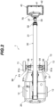
- the steering device 90 as shown in FIGS. 2 and 3 , has a front-wheel turning mechanism 93 connected to the left and right front wheels 12, a front-wheel steering cylinder 92 for driving the front-wheel turning mechanism 93 to change steering angles of the left and right front wheels 12 (a deflection angle of the front wheel 12 relative to a longitudinal central axis of the traveling body 10), a rear-wheel turning mechanism 91 connected to the left and right rear wheels 13, a rear-wheel steering cylinder 94 for driving the rear-wheel turning mechanism 91 to change steering angles of the left and right rear wheels 13 (a deflection angle of the rear wheel 13 relative to the longitudinal central axis of the traveling body 10), a front-wheel steering angle detector 96 for detecting the steering angles of the left and right front wheels 12, and a rear-wheel steering angle detector 97 for detecting the steering angles of the left and right rear wheels 13.
- the rear-wheel turning mechanism 91 has a pair of left and right rear-wheel knuckle arms 91a supporting the left and right rear wheels 13 swingably around respective rear-wheel kingpin pivots 95, and a rear-wheel tie rod 91b connecting the left or right rear-wheel knuckle arms 91a via respective connecting pins P1.
- the rear-wheel steering cylinder 94 has one end connected to the right rear-wheel knuckle arm 91a via a connecting pin P2, and has the other end connected to a cylinder connecting portion (not shown) of the traveling body frame 11 via a connecting pin.
- the steering device 90 is configured to actuate the rear-wheel steering cylinder 94 to extend and contract axially, thereby swinging the right rear wheel 13 around the rear-wheel kingpin pivot 95, and swinging the left rear wheel 13 via the rear tie rod 91b at the same time and in the same direction as the right rear wheel 13 so that the steering angles of the left and right rear wheels 13 can be changed.
- the front-wheel turning mechanism 93 is configured similarly to the rear-wheel turning mechanism 91 described above. Though not shown, the front-wheel turning mechanism 93 has a pair of left and right front-wheel knuckle arms supporting the left and right front wheels 12 swingably around a front-wheel kingpin pivot, and a front-wheel tie rod connecting the left and right front-wheel knuckle arms via a connecting pin.
- the front-wheel steering cylinder 92 has one end connected to the right front-wheel knuckle arm via a connecting pin, and has the other end connected to a cylinder connecting portion of the traveling body frame 11 via a connecting pin.
- the steering device 90 is configured to actuate the front-wheel steering cylinder 92 to extend and contract axially, thereby swinging the right front wheel 12 around the front-wheel kingpin pivot, and swinging the left front wheel 12 via the front tie rod at the same time and in the same direction as the right front wheel 12 so that the steering angles of the left and right front wheels 12 can be changed.
- the traveling body 10 is provided with two front-wheel brake cylinders 18 for braking respective rotations of the left and right front wheels 12, and two rear-wheel brake cylinders 19 for braking respective rotations of the left and right rear wheels 13.
- the front-wheel brake cylinders 18 are negative brakes (also see FIG. 4 ) that brake and lock rotations of motor shafts of the front-wheel travel motors 16 by forces of springs contained therein, thereby braking the rotations of the front wheels 12 when the front-wheel brake cylinders 18 are not supplied with the hydraulic fluid.
- the rear-wheel brake cylinders 19, similarly to the front-wheel braking cylinders 18, are negative brakes that brake and lock rotations of motor shafts of the rear-wheel travel motors 17 by forces of springs contained therein, thereby braking the rotations of the rear wheels 13 when the rear-wheel brake cylinders 19 are not supplied with the hydraulic fluid.
- the rotating body 20 is provided with a hydraulic unit 80 for serving as a driving source for the left and right front-wheel travel motors 16, the left and right rear-wheel travel motors 17, the left and right front-wheel brake cylinders 18, the left and right rear-wheel brake cylinders 19, the front-wheel steering cylinder 92, the rear-wheel steering cylinder 94, the rotation motor 26, the boom vertical swing cylinder 35, the boom axial extension cylinder 36, the swing motor 46, and the like, and supplying these hydraulic actuators with the hydraulic fluid.
- the hydraulic unit 80 has an engine E, the hydraulic pump P driven by the engine E, a hydraulic fluid tank T, and a control valve unit 85 for controlling a supplying direction and a supply amount of the hydraulic fluid supplied from the hydraulic pump P to each of the hydraulic actuators.
- the control valve unit 85 has a plurality of control valves V1 to V10 provided so as to correspond to the respective oil hydraulic actuators.
- the rotating body 20 is provided with a controller 50 into which an operation signal is inputted from the operation device 70 provided on the work platform 40.
- the controller 50 receives an operation signal from the operation device 70, the controller 50 outputs a command signal corresponding to the operation signal to the control valve unit 85 of the hydraulic unit 80.
- the controller 50 outputs a command signal corresponding to a tilting operation direction and an operation amount of the rotation operation lever 74 of the rotation operation lever 74 to the rotation control valve V7 of the control valve unit 85 to control a spool moving direction and a valve opening position of the rotation control valve V7, thereby driving the rotation motor 26 to actuate the rotating body 20 to rotate relative to the traveling body 10.
- the controller 50 When an operation signal is inputted from the boom operation lever 75 into the controller 50, the controller 50 outputs a command signal corresponding to a tilting operation direction and an operation amount of the boom operation lever 75 into the vertical swing and axial extension control valves V8, V9 of the control valve unit 85 to control a spool moving direction and a valve opening position of the vertical swing and axial extension control valves V8, V9, thereby driving the boom vertical swing cylinder 35 and the boom axial extension cylinder 36 to actuate the boom 30 to swing vertically and to extend and contract axially.
- the controller 50 when an operation signal is inputted from the horizontal swing operation lever 76 into the controller 50, the controller 50 outputs a command signal corresponding to a tilting operation direction and an operation amount of the rotation operation lever 74 to the swing control valve V10 of the control valve unit 85 to control a spool moving direction and a valve opening position of the swing control valve V10, thereby driving the swing motor 46 to actuate the work platform 40 to swing horizontally relative to the vertical post 37.
- the vehicle with an aerial work platform 1 has a rotation angle detector 61 for detecting a rotation angle of the rotating body 20 relative to the traveling body 10, a boom vertical swing angle detector 62 for detecting the vertical swing angle of the boom 30 relative to the rotating body 20, a boom extension amount detector 63 for detecting an extension amount of the boom 30, a horizontal swing angle detector 64 for detecting a horizontal swing angle (rotation angle) of the work platform 40 relative to the boom 30 (vertical post 37), and an inclination angle detector 65 for detecting an inclination angle of the traveling body frame 11 relative to a horizontal plane, and a detection signal from each of these detectors is inputted into the controller 50.
- the controller 50 constantly calculates and stores the moving position of the work platform 40 relative to the traveling body 10 on the basis of the detection signals from these respective detectors.
- the traveling operation lever 71 is configured to be operable to tilt both frontward and rearward from the neutral position extending vertically, and outputs to the controller 50 an operation signal for setting a traveling direction and a target speed of the traveling body 10 according to a tilting operation direction and an operation amount from the neutral position.
- a frontward tilting operation of the traveling operation lever 71 is equivalent to a forward traveling signal of the traveling body 10
- a rearward tilting operation thereof is equivalent to a reverse traveling signal of the traveling body 10
- a returning operation to the neutral position is equivalent to a stop signal of the traveling body 10.
- the controller 50 When an operation signal from the traveling operation lever 71 is inputted into the controller 50, the controller 50 outputs command signals corresponding to the operation signal to the front-wheel traveling control valve V1, the rear-wheel traveling control valve V2, the front-wheel brake control valve V5, and the rear-wheel brake control valve V6 of the traveling control valve unit 85 to control rotation actuation of the front-wheel travel motors 16, 16 and the rear-wheel travel motors 17, 17, namely driving of the front wheels 12, 12 and the rear wheels 13, 13.
- the controller 50 stops outputting the command signals to the front-wheel traveling control valve V1 and the rear-wheel traveling control valve V2, thereby stopping the supply of the hydraulic fluid to the front-wheel travel motors 16, 16 and the rear-wheel travel motors 17, 17. Furthermore, when no operation signal is outputted, the controller 50, except during steering restriction, in principle, stops outputting the command signals to the front-wheel brake control valve V5 and the rear-wheel control valve V6.
- the front-wheel and rear-wheel brake control valves V5, V6 are each a three-port two-position solenoid operated directional control valve, and they shut off the supply of the hydraulic fluid from the hydraulic pump P to the front-wheel brake cylinders 18, 18 and the rear-wheel brake cylinders 19, 19 when outputting of the command signals from the controller 50 is stopped and the solenoids are put into a non-energized state.
- the left and right front-wheel and rear-wheel brake cylinders 18, 19 are each a negative brake, as mentioned above, and they brake and lock the rotations of the motor shafts of the front-wheel travel motors 16, 16 and the rear-wheel travel motors 17, 17 when the supply of the hydraulic fluid is stopped, thereby braking the rotations of the front wheels 12, 12 and the rear wheels 13, 13.
- the controller 50 When the traveling operation lever 71 is operated to tilt frontward or rearward from the neutral position and a forward or reverse traveling signal is inputted into the controller 50, the controller 50 outputs command signals to the front-wheel brake control valve V5 and the rear-wheel brake control valve V6.
- the front-wheel and rear-wheel brake control valves V5, V6 supply the hydraulic fluid from the hydraulic pump P to the front-wheel brake cylinders 18, 18 and the rear-wheel brake cylinders 19, 19, respectively.
- the left and right front-wheel and rear-wheel brake cylinders 18, 19 respectively allow the rotations of the motor shafts of the front-wheel travel motors 16, 16 and the rear-wheel travel motors 17, 17, namely the rotations of the front wheels 12, 12 and the rear wheels 13, 13.
- the controller 50 outputs command signals corresponding to the forward or reverse traveling signal to the front-wheel traveling control valve V1 and the rear-wheel traveling control valve V2 to supply the hydraulic fluid to the front-wheel travel motors 16, 16 and the rear-wheel travel motors 17, 17, thereby driving the front-wheel travel motors 16, 16 and the rear-wheel travel motors 17, 17 into rotation in a rotating direction and at a rotation speed corresponding to the forward or reverse traveling signal to cause the traveling body 10 to travel forward or in reverse.
- the steering dial 72 is provided with a rotatable circular dial base portion 72a and a stick-like rotational position pointing portion 72b provided in an outward projecting manner at a position on an outer edge of the dial base portion 72a.
- This steering dial 72 is configured to be operable to twist by about 90 degrees both right-handedly (clockwise) and left-handedly (counterclockwise) relative to the neutral position in which the rotational position pointing portion 72b is oriented to a predetermined reference position P 0 , and outputs to the controller 50 an operation signal for setting target steering angles of the front wheels 12, 12 and the rear wheels 13, 13 according to a twisting operation direction and an operation amount from the reference position P 0 .
- a right-handed twisting operation of the steering dial 72 is equivalent to a steering signal for changing the traveling direction of the traveling body 10 to a rightward direction
- a left-handed twisting operation thereof is equivalent to a steering signal for changing the traveling direction of the traveling body 10 to a leftward direction
- a returning operation to the neutral position thereof is equivalent to a steering signal for changing the traveling direction of the traveling body 10 to a straightforward direction (for reducing the steering angles of the front wheels 12, 12 and the rear wheels 13, 13 to zero).
- a steering signal for setting a target steering angle for turning only the front wheels 12, 12 rightward according to the operation amount is outputted to the controller 50.
- a steering signal for setting a target steering angle for maximizing rightward steering angles of the front wheels 12, 12 is outputted to the controller 50.
- a steering signal for setting a target steering angle for turning only the rear wheels 13, 13 leftward (in a direction opposite to the rightward direction in which the front wheels 12, 12 are turned) according to the operation amount is outputted to the controller 50.
- a steering signal for setting a target steering angle for maximizing leftward steering angles of the rear wheels 13, 13 is outputted to the controller 50.
- a steering signal for setting a target steering angle for turning only the front wheels 12, 12 leftward according to the operation amount is outputted to the controller 50.
- a steering signal for setting a target steering angle for maximizing leftward steering angles of the front wheels 12, 12 is outputted to the controller 50.
- a steering signal for setting a target steering angle for turning only the rear wheels 13, 13 rightward (in a direction opposite to the leftward direction in which the front wheels 12, 12 are turned) according to the operation amount is outputted to the controller 50.
- a steering signal for setting a target steering angle for maximizing rightward steering angles of the rear wheels 13, 13 is outputted to the controller 50.
- the controller 50 allows actuation of the steering device 90, and outputs command signals corresponding to the steering signal to the front-wheel steering control valve V3 and the rear-wheel steering control valve V4 to actuate the front-wheel steering cylinder 92 and the rear-wheel steering cylinder 94 to actuate the front wheels 12, 12 and the rear wheels 13, 13 to turn so that the steering angles detected by the front-wheel and rear-wheel steering angle detectors 96, 97 will be target steering angles corresponding to the steering signal.
- FIG. 6 shows the steering dial 72 operated to the reference position P 0 and the front wheels 12, 12 and the rear wheels 13, 13 thus situated in the neutral position (a position where the steering angle is zero).
- FIG. 7 shows the steering dial 72 operated to the right middle twisted position P R1 . If the steering dial 72 is operated to twist right-handedly from the reference position P 0 toward the right middle twisted position P R1 , a steering signal for setting a target steering angle (an angle less than a maximum steering angle ⁇ 1 described later) for turning only the front wheels 12, 12 rightward according to the operation amount is outputted to the controller 50.
- a target steering angle an angle less than a maximum steering angle ⁇ 1 described later
- the controller 50 outputs a command signal corresponding to this steering signal to the front-wheel steering control valve V3 to actuate the front-wheel steering cylinder 92 to actuate the front wheels 12, 12 to turn rightward so that the steering angles of the front wheels 12, 12 detected by the front-wheel steering angle detector 96 will be the target steering angle corresponding to the operation amount of the steering dial 72.
- a steering signal for steering the rear wheels 13, 13 is not outputted from the steering dial 72 to the controller 50, and therefore the rear-wheel steering cylinder 94 is not actuated, so that the rear wheels 13, 13 are retained in the neutral position.
- a steering signal for setting a target steering angle (an angle equal to the maximum steering angle ⁇ 1 described later) for turning only the front wheels 12, 12 rightward to a maximum degree is outputted to the controller 50.
- a steering signal for steering the rear wheels 13, 13 is not outputted from the steering dial 72 to the controller 50, and therefore the rear-wheel steering cylinder 94 is not actuated, so that the rear wheels 13, 13 are retained in the neutral position.
- FIG. 8 shows the steering dial 72 operated to the maximum right twisted position P R2 . If the steering dial 72 is further operated to twist right-handedly from the right middle twisted position P R1 toward the maximum right twisted position P R2 , a steering signal for setting a target steering angle (an angle less than maximum steering angle ⁇ 2 described later) for turning only the rear wheels 13, 13 leftward according to the operation amount is outputted to the controller 50. Once this steering signal is inputted into the controller 50, the controller 50 determines whether the steering angles of the front wheels 12, 12 detected by the front-wheel steering angle detector 96 are the maximum steering angle ⁇ 1 or not.
- a target steering angle an angle less than maximum steering angle ⁇ 2 described later
- the controller 50 outputs a command signal corresponding to this steering signal to the rear-wheel steering control valve V4 to actuate the rear-wheel steering cylinder 94 to actuate the rear wheels 13, 13 to turn leftward so that the steering angles detected by the rear-wheel steering angle detector 97 will be the target steering angle corresponding to the operation amount of the steering dial 72.
- a steering signal of the front wheels 12, 12 is not outputted from the steering dial 72 to the controller 50, so that the front-wheel steering control valve V3 is retained in neutral. Therefore, the front-wheel steering cylinder 92 is not actuated, so that the front wheels 12, 12 are retained in a rightward maximum steering angle position.
- a steering signal for setting a target steering angle (an angle equal to the maximum steering angle ⁇ 2 described later) for turning only the rear wheels 13, 13 leftward to a maximum degree is outputted to the controller 50.
- a steering signal for setting a target steering angle for turning only the rear wheels 13, 13 rightward toward the neutral position according to the operation amount (operation position) is outputted to the controller 50.
- the controller 50 outputs a command signal corresponding to this steering signal to the rear-wheel steering control valve V4 to actuate the rear-wheel steering cylinder 94 to actuate the rear wheels 13, 13 to turn rightward so that the leftward steering angles of the rear wheels 13, 13 detected by the rear-wheel steering angle detector 97 will be the target steering angle corresponding to the operation amount of the steering dial 72.
- a steering signal of the front wheels 12, 12 is not outputted, from the steering dial 72 to the controller 50, so that the front-wheel steering control valve V3 is retained in neutral. Therefore, the front-wheel steering cylinder 92 is not actuated, so that the front wheels 12, 12 are retained in the rightward maximum steering angle position.
- a steering signal for setting a target steering angle for turning only the rear wheels 13, 13 to the neutral position is outputted to the controller 50.
- the controller 50 outputs a command signal corresponding to this steering signal to the rear-wheel steering control valve V4 to actuate the rear-wheel steering cylinder 94 to actuate the rear wheels 13, 13 to turn to the neutral position so that the steering angles of the rear wheels 13, 13 detected by the rear-wheel steering angle detector 97 will be ⁇ 0 .
- a steering signal for setting a target steering angle for turning only the front wheels 12, 12 leftward toward the neutral position according to the operation amount is outputted to the controller 50.
- the controller 50 determines whether the steering angles of the rear wheels 13, 13 detected by the rear-wheel steering angle detector 97 is zero ( ⁇ 0 ) or not.
- the controller 50 outputs a command signal corresponding to this steering signal to the front-wheel steering control valve V3 to actuate the front-wheel steering cylinder 92 to actuate the front wheels 12, 12 to turn leftward so that the steering angles of the front wheels 12, 12 detected by the front-wheel steering angle detector 96 will be the target steering angle corresponding to the operation amount of the steering dial 72.
- a steering signal of the rear wheels 13, 13 is not outputted from the steering dial 72 to the controller 50, so that the rear-wheel steering control valve V4 is retained in neutral. Therefore, the rear-wheel steering cylinder 94 is not actuated, so that the rear wheels 13, 13 are retained in the neutral position.
- a steering signal for setting the target steering angles of the front wheels 12, 12 to zero is outputted to the controller 50.
- the controller 50 outputs a command signal corresponding to this steering signal to the front-wheel steering control valve V3 to actuate the front-wheel steering cylinder 92 to turn the front wheels 12, 12 to the neutral position so that the respective steering angles detected by the front-wheel steering angle detector 96 will be zero ( ⁇ 0 ).
- steering signal of the rear wheels 13, 13 is not outputted, to the controller 50, so that the rear-wheel steering control valve V4 is retained in neutral. Therefore, the rear-wheel steering cylinder 94 is not actuated, so that the rear wheels 13, 13 are retained in the neutral position.
- Steering control of the front wheels 12, 12 and the rear wheels 13, 13 in the case where the steering dial 72 is operated to twist left-handedly from the reference position P 0 to the maximum left twisted position P L2 and in the case where the steering dial 72 is operated to return right-handedly from the maximum left twisted position P L2 to the reference position P 0 has the same basic content as the steering control described above except that the steering directions of the front wheels 12, 12 and the rear wheels 13, 13 are laterally reversed.
- the steering mode where only the front wheels 12, 12 are turned between the neutral position and the maximum steering angle position with the rear wheels 13, 13 retained in the neutral position and the steering mode where only the rear wheels 13, 13 are turned between the neutral position and the maximum steering angle position with the front wheels 12, 12 retained in the maximum steering angle position can be switched by only operating the steering dial 72 according to an operation amount thereof.
- This also enables the turning radius of the vehicle with an aerial work platform 1 (traveling body 10) during traveling to be continuously varied from a maximum turning radius to a minimum turning radius by only operating the steering dial 72. Therefore, the vehicle with an aerial work platform 1 has much better operability during steering than a vehicle with an aerial work platform configured to switch between the two-wheel steering mode and the four-wheel steering mode selectively by a selector switch or the like.
- a preferred embodiment according to the present invention has been described above, but the scope of the present invention is not limited to a scope shown in the embodiment described above.
- the front wheels 12, 12 and the rear wheels 13, 13 are actuated to turn from the neutral position, only the front wheels 12, 12 are actuated to turn if the steering angles of the front wheels 12, 12 are less than the maximum steering angle ⁇ 1 , and only the rear wheels 13, 13 are actuated to turn if the steering angles of the front wheels 12, 12 are the maximum steering angle ⁇ 1 , but the scope of the present invention is not limited thereto.
- the present invention may be configured in a manner such that when the front wheels 12, 12 and the rear wheels 13, 13 are actuated to turn from the neutral position, only the front wheels 12, 12 are actuated to turn if the steering angles of the front wheels 12, 12 are less than a predetermined angle ⁇ 3 ( ⁇ 0 ⁇ ⁇ 3 ⁇ ⁇ 1 ), the rear wheels 13, 13 are also actuated to turn in addition to the front wheels 12, 12 but in the opposite direction to the front wheels 12, 12 if the steering angles of the front wheels 12, 12 lie within an angular range from equal to or more than ⁇ 3 to less than ⁇ 1 , and only the rear wheels 13, 13 are actuated to turn if the steering angles of the front wheels 12, 12 reach the maximum steering angle ⁇ 1 .
- the present invention may be configured in a manner such that when the front wheels 12, 12 and the rear wheels 13, 13 are actuated to turn back from the maximum steering angle position to the neutral position, only the rear wheels 13, 13 are actuated to turn if the steering angles of the rear wheels 13, 13 are equal to or more than a predetermined angle ⁇ 4 ( ⁇ 0 ⁇ ⁇ 4 ⁇ ⁇ 2 ), the front wheels 12, 12 are also actuated to turn in addition to the rear wheels 13, 13 but in the opposite direction to the rear wheels 13, 13 if the steering angles of the rear wheels 13, 13 are less than ⁇ 4 and larger than ⁇ 0 , and only the front wheels 12, 12 are actuated to turn if the steering angles of the rear wheels 13, 13 reach ⁇ 0 .
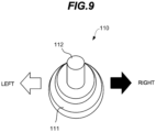
- the above embodiment has been described as being configured to be provided with the steering dial 72 as a steering operating means, but the present invention may be configured to be provided with a steering switch lever 110 such as shown in FIG. 9 instead of the steering dial 72.
- This steering switch lever 110 includes a base portion 111 and a stick-like operating portion 112 provided in an upward projecting manner on the base portion 111.
- the operating portion 112 is configured to be tiltable leftward and rightward, and a steering signal for changing the traveling direction of the vehicle to the leftward direction is outputted if the operating portion 112 is tilted leftward, whereas a steering signal for changing the traveling direction of the vehicle to the rightward direction is outputted if the operating portion 112 is tilted rightward.
- the steering switch lever 110 is different from the steering dial 72 in that a steering signal for returning the wheels to the neutral position is not outputted when the operating portion 112 is returned to the neutral position.
- the steering angles of the front wheels 12, 12 are directly detected by the front-wheel steering angle detector 96 in the embodiment described above, but the steering angles of the front wheels 12, 12 may be indirectly detected on the basis of a detection result of a stroke of the front-wheel steering cylinder 92 detected by a limit switch, a sensor, or the like.
- the steering angles of the rear wheels 13, 13 are directly detected by the rear-wheel steering angle detector 97 in the embodiment described above, but the steering angles of the rear wheels 13, 13 may be indirectly detected on the basis of a detection result of a stroke of the rear-wheel steering cylinder 94 detected by a limit switch, a sensor, or the like.
- a limit switch for front wheels for detecting that (whether or not) the steering angles of the front wheels 12, 12 reach the maximum steering angle may be provided in the front-wheel turning mechanism 93 instead of the front-wheel steering angle detector 96.
- the front wheels 12, 12 and the rear wheels 13, 13 are actuated to turn from the neutral position, on the basis of a detection result from the limit switch for front wheels, only the front wheels 12, 12 may be actuated to turn if the steering angles of the front wheels 12, 12 are less than the maximum steering angle ⁇ 1 (does not reach ⁇ 1 ), and only the rear wheels 13, 13 may be actuated to turn if (after) the steering angles of the front wheels 12, 12 reach the maximum steering angle ⁇ 1 .
- a limit switch for rear wheels (not shown) for detecting that the steering angles of the rear wheels 13, 13 reach (return to) zero ( ⁇ 0 ) may be provided in the rear-wheel turning mechanism 91 instead of the rear-wheel steering angle detector 97.
- a four-wheel driving configuration having the front-wheel travel motors 16, 16 and the rear-wheel travel motors 17, 17 has been employed in the embodiment described above, but a two-wheel driving configuration where either the front wheels 12, 12 or the rear wheels 13, 13 are driven may be employed.
Abstract
Description
- The present invention relates to a steering control apparatus for a work vehicle that can change a traveling direction by steering front wheels and rear wheels.
- As examples of work vehicles having a steering control apparatus that can change a traveling direction by steering front wheels and rear wheels, a so-called self-propelled vehicle with an aerial work platform and a self-propelled excavation vehicle and the like are known. They are widely used for civil engineering and construction work, shipbuilding work, and the like. The self-propelled vehicle is provided with a boom or scissors-link type lifting apparatus and a work platform supported and moved up and down by the lifting apparatus on a vehicle body. The self-propelled excavation vehicle is provided with an excavating apparatus on a vehicle body. Such work vehicles are configured to automatically apply a brake for restricting the wheels from rotating when the vehicle is stationary so that work at heights and the like can be performed safely. Moreover, the vehicles are configured to release the brake actuation when a traveling operation is performed, and also to drive the wheels into rotation on the basis of the traveling operation so that the vehicles can travel and move.
- Such work vehicles as mentioned above include a two-wheel steering work vehicle that actuates either the front wheels or the rear wheels provided on the front, rear, left, and right of the vehicle body to turn to change a traveling direction, and a four-wheel steering work vehicle that actuates both the front wheels and the rear wheels to turn to change a traveling direction. In addition, some four-wheel steering work vehicles are known as a work vehicle configured to be switchable between a two-wheel steering mode and a four-wheel steering mode (for example, see
Japanese Laid-Open Patent Publication No. 2020-6905(A - In the work vehicle configured to be switchable between the two-wheel steering mode and the counter-phase four-wheel steering mode, the counter-phase four-wheel steering mode is selected mainly when it is desired to reduce a turning radius of the vehicle, whereas the two-wheel steering mode is selected in a normal case where such a necessity does not arise. In conventional work vehicles, switching between the two-wheel steering mode and the counter-phase four-wheel steering mode is performed by an operator operating a selector switch or the like. Therefore, in such a case where the operator selects the two-wheel steering mode and steers, and simultaneously starts rotational travel of the vehicle, but in the process the operator desires to reduce the turning radius of the vehicle, the operator is required to interrupt steering and the like and operate the selector switch or the like to switch from the two-wheel steering mode to the counter-phase four-wheel steering mode, and accordingly a reduction in operability during steering is problematic.
- The present invention has been made in view of these circumstances, and an object thereof is to provide a work vehicle steering control apparatus that enables improvement in operability during steering of a work vehicle having steerable front and rear wheels.
- In order to solve the problem described above, in accordance with an embodiment of the present invention, a work vehicle steering control apparatus comprises a vehicle body (for example, a traveling
body frame 11 in an embodiment), front wheels rotatably provided at left and right sides of front part of the vehicle body and rear wheels rotatably provided at left and right sides of rear part of the vehicle body, the front wheels and the rear wheels being able to be steered respectively; a steering actuator (for example, a front-wheel steering cylinder 92 and a rear-wheel steering cylinder 94 in the embodiment) for steering the front wheels and/or the rear wheels to turn the work vehicle; a steering operation device (for example, asteering dial 72 in the embodiment) for performing a steering operation of the front wheels and the rear wheels; a steering actuation control device (for example, acontroller 50 in the embodiment) for controlling actuation of the steering actuator on the basis of the steering operation performed by the steering operation device; and a steering angle detector for detecting steering angles of the front wheels and the rear wheels. The steering actuation control device is configured in a manner such that when a directional-change steering operation for changing a vehicle traveling direction is performed by the steering operation device, on the basis of a detection result from the steering angle detector, when the steering angles of one set of wheels of either the front wheels and the rear wheels are less than a predetermined angle (for example, θ1 in the embodiment), the steering actuation control device controls the steering actuator to steer only the one set of wheels of the front wheels and the rear wheels to turn the work vehicle in response to the directional-change steering operation, and when the steering angles of the one set of wheels are equal to or more than the predetermined angle, the steering actuation control device controls the steering actuator to steer the other set of wheels of the front wheels and the rear wheels in a direction opposite to steering direction of the one set of wheels in response to the directional-change steering operation. - In the steering control apparatus thus configured, it is preferred that the predetermined angle is a maximum steering angle of the one set of wheels.
- In the steering control apparatus thus configured, a detection switch for detecting that the steering angles of the one set of wheels reach the maximum steering angle may be included instead of the steering angle detector.
- In the steering control apparatus thus configured, it is preferred that the steering actuation control device be configured in a manner such that when a return steering operation for turning the front wheels and the rear wheels toward a neutral position is performed by the steering operation device after the directional-change steering operation is performed by the steering operation device,
- on the basis of a detection result from the steering angle detector,
- when the steering angles of the other set of wheels do not reach a steering angle in the neutral position, the steering actuation control device controls the steering actuator to actuate only the other set of wheels to turn in response to the return steering operation, and
- when the steering angles of the other set of wheels reach the steering angle in the neutral position, the steering actuation control device controls the steering actuator to actuate only the one set of wheels to turn in a direction opposite to the other set of wheels while retaining the other set of wheels in the neutral position in response to the return steering operation.
- In accordance with the steering control apparatus according to the present invention, when the directional change steering operation for changing the vehicle traveling direction is performed, and when the steering angles of one set of wheels of front wheels and rear wheels are less than a predetermined angle, only the one set of wheels are actuated to turn in response to the directional change steering operation, and when the steering angles of the one set of wheels are equal to or more than the predetermined angle, the other set of wheels of the front wheels and the rear wheels are actuated to turn in the direction opposite to the one set of wheels in response to the directional change steering operation. Accordingly, a steering mode in which only the one set of wheels are turned in response to the directional change steering operation and a steering mode in which the other set of wheels are also turned in response to the directional change steering operation can be smoothly switched by simply performing the directional change steering operation. Therefore, operability during the directional change steering operation can be improved.
- Further scope of applicability of the present invention will become apparent from the detailed description given hereinafter. However, it should be understood that the detailed description and specific examples, while indicating preferred embodiments of the invention, are given by way of illustration only, since various changes and modifications within the spirit and scope of the invention will become apparent to those skilled in the art from this detailed description.
- The present invention will become more fully understood from the detailed description given herein below and the accompanying drawings which are given by way of illustration only and thus are not limitative of the present invention.
-
FIG. 1 is a side view of a self-propelled vehicle with an aerial work platform as an example of a work vehicle provided with a steering control apparatus according to the present invention; -
FIG. 2 is a top view of the vehicle with an aerial work platform; -
FIG. 3 is a block diagram illustrating an actuation control configuration of the vehicle with an aerial work platform; -
FIG. 4 is a hydraulic circuit diagram illustrating a part of a traveling control configuration of the vehicle with an aerial work platform; -
FIG. 5 is a schematic diagram illustrating a steering dial configuration of the vehicle with an aerial work platform; -
FIG. 6 is a schematic diagram illustrating a steering control example with the steering dial operated to a reference position; -
FIG. 7 is a schematic diagram illustrating a steering control example with the steering dial operated to a right middle twisted position; -
FIG. 8 is a schematic diagram illustrating a steering control example with the steering dial operated to a maximum right twisted position; and -
FIG. 9 is a schematic diagram illustrating a steering switch lever configuration usable as an alternative to the steering dial. - An embodiment of the present invention will be described below with reference to the drawings. A self-propelled vehicle with an aerial work platform 1 is shown in
FIGS. 1 and2 as an example of a work vehicle provided with a steering control apparatus according to the present invention. The vehicle with an aerial work platform 1 includes a travelingbody 10 configured to be travelable, a rotatingbody 20 provided horizontally rotatably on top of the travelingbody 10, aboom 30 provided vertically swingably on top of the rotatingbody 20, and awork platform 40 provided at a distal end of theboom 30. - The traveling
body 10 has a pair of left and rightfront wheels 12 and a pair of left and rightrear wheels 13 provided rotatably on a travelingbody frame 11. Thetraveling body 10 has two front-wheel travel motors 16 (seeFIG. 3 ) for driving the respective left and rightfront wheels 12 into rotation, and two rear-wheel travel motors 17 (seeFIG. 3 ) for driving the respective left and rightrear wheels 13 into rotation. The travelingbody 10 is configured to be travelable and movable in a desired direction by the front-wheel and rear-wheel travel motors 16, 17 driving into rotation the left and rightfront wheels 12 andrear wheels 13, respectively, and simultaneously by steering these respectivefront wheels 12 andrear wheels 13. - A
rotation mechanism 15 is provided centrally on top of thetraveling body frame 11. Therotation mechanism 15 has an outer ring fixed to thetraveling body frame 11, an inner ring fixed to the rotatingbody 20 and engaged with the outer ring, a rotation motor 26 (seeFIG. 3 ) provided on the rotatingbody 20, and a rotary center joint for supplying a hydraulic fluid from a hydraulic pump P (seeFIG. 3 ) provided on the rotatingbody 20 to the front-wheel and rear-wheel travel motors 16, 17 and the like provided on thetraveling body 10. The rotatingbody 20 is horizontally rotatably mounted to the travelingbody frame 11 via therotation mechanism 15, and configured to be rotatable leftward and rightward relative to thetraveling body 10 by actuating therotation motor 26 to rotate forward or in reverse. - The
boom 30 is vertically swingably provided on top of the rotatingbody 20 via a pivotally-connectingpin 34. Theboom 30 can be actuated to vertically swing relative to the rotatingbody 20 by a boom vertical swing cylinder 35 (seeFIG. 3 ) provided in a bridging manner between the rotatingbody 20 and theboom 30. Theboom 30 has abase boom 31 connected pivotally to the rotatingbody 20, and anintermediate boom 32 and atop boom 33 combined with thebase boom 31 in a telescopic form, and is configurated to be axially extendable. Theboom 30 can be actuated to axially extend and contract by a boom axial extension cylinder 36 (seeFIG. 3 ) provided in theboom 30. - A
vertical post 37 is vertically swingably provided at a distal end of thetop boom 33 via a pivotally-connecting pin. Thework platform 40 is provided so as to be rotatable leftward and rightward (horizontally swingable) on top of thevertical post 37. An upper leveling cylinder (not shown) is provided in a bridging manner between the distal end of thetop boom 33 and thevertical post 37. A hydraulic hose forms a closed circuit between this upper leveling cylinder and a lower leveling cylinder (not shown) provided in a bridging manner between thebase boom 31 and therotating body 20, and the upper leveling cylinder is configured to be actuated to axially extend and contract in response to axial extension and contraction of the lower leveling cylinder, thereby swinging thevertical post 37 vertically relative to thetop boom 33 to keep a floor surface of thework platform 40 horizontal at all times regardless of a vertical swing angle of theboom 30. - The
work platform 40 is configured to be actuatable to rotate leftward and rightward (horizontally swing) relative to thevertical post 37 by a swing motor 46 (seeFIG. 3 ) provided on thework platform 40. Thework platform 40 has a substantially rectangular working floor 41 a worker can get onto, and ahandrail 42 erected around thework platform 41. Anoperation device 70 for performing a traveling operation of thetraveling body 10, an actuation operation of theboom 30, and the like provided on thework platform 40. - The
operation device 70, as shown inFIG. 3 , has atraveling operation lever 71 for switching between start and stop and between forward movement and reverse movement of the travelingbody 10, and the like, asteering dial 72 for performing a steering operation of the traveling body 10 (steering of thefront wheels 12 and the rear wheels 13), arotation operation lever 74 for performing a rotating operation of the rotatingbody 20, a boom operation lever 75 for performing vertical swing and axial extension operations of theboom 30, and a horizontal swing operation lever 76 for performing a swing operation (rotation operation) of thework platform 40. Each of the operation levers of theoperation device 70 is situated in a neutral position where the operation levers are in a vertical attitude when the lever is not operated, and is configured to be operable to tilt in each direction relative to this neutral position. The vehicle with an aerial work platform 1 is configured in a manner such that a worker can get onto thework platform 40 and can operate the travelingoperation lever 71, thesteering dial 72, and the like, thereby causing the vehicle with an aerial work platform 1 to travel and move to a desired working position, and can also operate therotation operation lever 74, theboom operation lever 75, and the like, thereby moving thework platform 40 up and down to a desired height position. - The left and right
front wheels 12 andrear wheels 13 and thesteering dial 72 are interlockingly connected to each other via asteering device 90. Thesteering device 90, as shown inFIGS. 2 and3 , has a front-wheel turning mechanism 93 connected to the left and rightfront wheels 12, a front-wheel steering cylinder 92 for driving the front-wheel turning mechanism 93 to change steering angles of the left and right front wheels 12 (a deflection angle of thefront wheel 12 relative to a longitudinal central axis of the traveling body 10), a rear-wheel turning mechanism 91 connected to the left and rightrear wheels 13, a rear-wheel steering cylinder 94 for driving the rear-wheel turning mechanism 91 to change steering angles of the left and right rear wheels 13 (a deflection angle of therear wheel 13 relative to the longitudinal central axis of the traveling body 10), a front-wheelsteering angle detector 96 for detecting the steering angles of the left and rightfront wheels 12, and a rear-wheelsteering angle detector 97 for detecting the steering angles of the left and rightrear wheels 13. - The rear-
wheel turning mechanism 91 has a pair of left and right rear-wheel knuckle arms 91a supporting the left and rightrear wheels 13 swingably around respective rear-wheel kingpin pivots 95, and a rear-wheel tie rod 91b connecting the left or right rear-wheel knuckle arms 91a via respective connecting pins P1. The rear-wheel steering cylinder 94 has one end connected to the right rear-wheel knuckle arm 91a via a connecting pin P2, and has the other end connected to a cylinder connecting portion (not shown) of the travelingbody frame 11 via a connecting pin. Thesteering device 90 is configured to actuate the rear-wheel steering cylinder 94 to extend and contract axially, thereby swinging the rightrear wheel 13 around the rear-wheel kingpin pivot 95, and swinging the leftrear wheel 13 via therear tie rod 91b at the same time and in the same direction as the rightrear wheel 13 so that the steering angles of the left and rightrear wheels 13 can be changed. - The front-
wheel turning mechanism 93 is configured similarly to the rear-wheel turning mechanism 91 described above. Though not shown, the front-wheel turning mechanism 93 has a pair of left and right front-wheel knuckle arms supporting the left and rightfront wheels 12 swingably around a front-wheel kingpin pivot, and a front-wheel tie rod connecting the left and right front-wheel knuckle arms via a connecting pin. The front-wheel steering cylinder 92 has one end connected to the right front-wheel knuckle arm via a connecting pin, and has the other end connected to a cylinder connecting portion of the travelingbody frame 11 via a connecting pin. Thesteering device 90 is configured to actuate the front-wheel steering cylinder 92 to extend and contract axially, thereby swinging theright front wheel 12 around the front-wheel kingpin pivot, and swinging theleft front wheel 12 via the front tie rod at the same time and in the same direction as theright front wheel 12 so that the steering angles of the left and rightfront wheels 12 can be changed. - The traveling
body 10 is provided with two front-wheel brake cylinders 18 for braking respective rotations of the left and rightfront wheels 12, and two rear-wheel brake cylinders 19 for braking respective rotations of the left and rightrear wheels 13. The front-wheel brake cylinders 18 are negative brakes (also seeFIG. 4 ) that brake and lock rotations of motor shafts of the front-wheel travel motors 16 by forces of springs contained therein, thereby braking the rotations of thefront wheels 12 when the front-wheel brake cylinders 18 are not supplied with the hydraulic fluid. The rear-wheel brake cylinders 19, similarly to the front-wheel braking cylinders 18, are negative brakes that brake and lock rotations of motor shafts of the rear-wheel travel motors 17 by forces of springs contained therein, thereby braking the rotations of therear wheels 13 when the rear-wheel brake cylinders 19 are not supplied with the hydraulic fluid. - The rotating
body 20 is provided with ahydraulic unit 80 for serving as a driving source for the left and right front-wheel travel motors 16, the left and right rear-wheel travel motors 17, the left and right front-wheel brake cylinders 18, the left and right rear-wheel brake cylinders 19, the front-wheel steering cylinder 92, the rear-wheel steering cylinder 94, therotation motor 26, the boomvertical swing cylinder 35, the boomaxial extension cylinder 36, theswing motor 46, and the like, and supplying these hydraulic actuators with the hydraulic fluid. Thehydraulic unit 80 has an engine E, the hydraulic pump P driven by the engine E, a hydraulic fluid tank T, and acontrol valve unit 85 for controlling a supplying direction and a supply amount of the hydraulic fluid supplied from the hydraulic pump P to each of the hydraulic actuators. Thecontrol valve unit 85 has a plurality of control valves V1 to V10 provided so as to correspond to the respective oil hydraulic actuators. - The rotating
body 20 is provided with acontroller 50 into which an operation signal is inputted from theoperation device 70 provided on thework platform 40. When thecontroller 50 receives an operation signal from theoperation device 70, thecontroller 50 outputs a command signal corresponding to the operation signal to thecontrol valve unit 85 of thehydraulic unit 80. For example, if an operation signal is inputted from therotation operation lever 74 of theoperation device 70 into thecontroller 50, thecontroller 50 outputs a command signal corresponding to a tilting operation direction and an operation amount of therotation operation lever 74 of therotation operation lever 74 to the rotation control valve V7 of thecontrol valve unit 85 to control a spool moving direction and a valve opening position of the rotation control valve V7, thereby driving therotation motor 26 to actuate therotating body 20 to rotate relative to the travelingbody 10. - When an operation signal is inputted from the
boom operation lever 75 into thecontroller 50, thecontroller 50 outputs a command signal corresponding to a tilting operation direction and an operation amount of theboom operation lever 75 into the vertical swing and axial extension control valves V8, V9 of thecontrol valve unit 85 to control a spool moving direction and a valve opening position of the vertical swing and axial extension control valves V8, V9, thereby driving the boomvertical swing cylinder 35 and the boomaxial extension cylinder 36 to actuate theboom 30 to swing vertically and to extend and contract axially. In addition, when an operation signal is inputted from the horizontalswing operation lever 76 into thecontroller 50, thecontroller 50 outputs a command signal corresponding to a tilting operation direction and an operation amount of therotation operation lever 74 to the swing control valve V10 of thecontrol valve unit 85 to control a spool moving direction and a valve opening position of the swing control valve V10, thereby driving theswing motor 46 to actuate thework platform 40 to swing horizontally relative to thevertical post 37. - In order to perform actuation control of the
rotating body 20, theboom 30, and thework platform 40 in this manner, the vehicle with an aerial work platform 1 has arotation angle detector 61 for detecting a rotation angle of therotating body 20 relative to the travelingbody 10, a boom verticalswing angle detector 62 for detecting the vertical swing angle of theboom 30 relative to therotating body 20, a boomextension amount detector 63 for detecting an extension amount of theboom 30, a horizontalswing angle detector 64 for detecting a horizontal swing angle (rotation angle) of thework platform 40 relative to the boom 30 (vertical post 37), and aninclination angle detector 65 for detecting an inclination angle of the travelingbody frame 11 relative to a horizontal plane, and a detection signal from each of these detectors is inputted into thecontroller 50. Thecontroller 50 constantly calculates and stores the moving position of thework platform 40 relative to the travelingbody 10 on the basis of the detection signals from these respective detectors. - Next, traveling control and steering control of the vehicle with an aerial work platform 1 (traveling body 10) will be described with additional reference to
FIGS. 3 to 5 . The travelingoperation lever 71 is configured to be operable to tilt both frontward and rearward from the neutral position extending vertically, and outputs to thecontroller 50 an operation signal for setting a traveling direction and a target speed of the travelingbody 10 according to a tilting operation direction and an operation amount from the neutral position. A frontward tilting operation of the travelingoperation lever 71 is equivalent to a forward traveling signal of the travelingbody 10, a rearward tilting operation thereof is equivalent to a reverse traveling signal of the travelingbody 10, and a returning operation to the neutral position is equivalent to a stop signal of the travelingbody 10. When an operation signal from the travelingoperation lever 71 is inputted into thecontroller 50, thecontroller 50 outputs command signals corresponding to the operation signal to the front-wheel traveling control valve V1, the rear-wheel traveling control valve V2, the front-wheel brake control valve V5, and the rear-wheel brake control valve V6 of the travelingcontrol valve unit 85 to control rotation actuation of the front-wheel travel motors 16, 16 and the rear-wheel travel motors 17, 17, namely driving of thefront wheels rear wheels - When the traveling
operation lever 71 is in the neutral position or operated to return from an operated-to-tilt state to the neutral position, and stops outputting the operation signal, thecontroller 50 stops outputting the command signals to the front-wheel traveling control valve V1 and the rear-wheel traveling control valve V2, thereby stopping the supply of the hydraulic fluid to the front-wheel travel motors 16, 16 and the rear-wheel travel motors 17, 17. Furthermore, when no operation signal is outputted, thecontroller 50, except during steering restriction, in principle, stops outputting the command signals to the front-wheel brake control valve V5 and the rear-wheel control valve V6. The front-wheel and rear-wheel brake control valves V5, V6 are each a three-port two-position solenoid operated directional control valve, and they shut off the supply of the hydraulic fluid from the hydraulic pump P to the front-wheel brake cylinders wheel brake cylinders controller 50 is stopped and the solenoids are put into a non-energized state. The left and right front-wheel and rear-wheel brake cylinders front wheels rear wheels - When the traveling
operation lever 71 is operated to tilt frontward or rearward from the neutral position and a forward or reverse traveling signal is inputted into thecontroller 50, thecontroller 50 outputs command signals to the front-wheel brake control valve V5 and the rear-wheel brake control valve V6. When the solenoids are energized by the command signals from thecontroller 50, the front-wheel and rear-wheel brake control valves V5, V6 supply the hydraulic fluid from the hydraulic pump P to the front-wheel brake cylinders wheel brake cylinders wheel brake cylinders front wheels rear wheels controller 50 outputs command signals corresponding to the forward or reverse traveling signal to the front-wheel traveling control valve V1 and the rear-wheel traveling control valve V2 to supply the hydraulic fluid to the front-wheel travel motors 16, 16 and the rear-wheel travel motors 17, 17, thereby driving the front-wheel travel motors 16, 16 and the rear-wheel travel motors 17, 17 into rotation in a rotating direction and at a rotation speed corresponding to the forward or reverse traveling signal to cause the travelingbody 10 to travel forward or in reverse. - The
steering dial 72, as shown inFIG. 5 , is provided with a rotatable circulardial base portion 72a and a stick-like rotationalposition pointing portion 72b provided in an outward projecting manner at a position on an outer edge of thedial base portion 72a. Thissteering dial 72 is configured to be operable to twist by about 90 degrees both right-handedly (clockwise) and left-handedly (counterclockwise) relative to the neutral position in which the rotationalposition pointing portion 72b is oriented to a predetermined reference position P0, and outputs to thecontroller 50 an operation signal for setting target steering angles of thefront wheels rear wheels steering dial 72 is equivalent to a steering signal for changing the traveling direction of the travelingbody 10 to a rightward direction, a left-handed twisting operation thereof is equivalent to a steering signal for changing the traveling direction of the travelingbody 10 to a leftward direction, and a returning operation to the neutral position thereof is equivalent to a steering signal for changing the traveling direction of the travelingbody 10 to a straightforward direction (for reducing the steering angles of thefront wheels rear wheels - More specifically, if the
steering dial 72 is operated to twist right-handedly within an angular range α1 from the reference position P0 to a right middle twisted position PR1 (seeFIG. 5 ), a steering signal for setting a target steering angle for turning only thefront wheels controller 50. In particular, if thesteering dial 72 is operated to twist right-handedly until the rotationalposition pointing portion 72b of thesteering dial 72 is oriented to the right middle twisted position PR1, a steering signal for setting a target steering angle for maximizing rightward steering angles of thefront wheels controller 50. In addition, if thesteering dial 72 is operated to twist right-handedly within an angular range α2 from the right middle twisted position PR1 to a maximum right twisted position PR2, a steering signal for setting a target steering angle for turning only therear wheels front wheels controller 50. In particular, if thesteering dial 72 is operated to twist right-handedly until the rotationalposition pointing portion 72b of thesteering dial 72 is oriented to the maximum right twisted position PR2, a steering signal for setting a target steering angle for maximizing leftward steering angles of therear wheels controller 50. - Similarly, if the
steering dial 72 is operated to twist left-handedly within an angular range β1 from the reference position P0 to a left middle twisted position PL1, a steering signal for setting a target steering angle for turning only thefront wheels controller 50. In particular, if thesteering dial 72 is operated to twist left-handedly until the rotationalposition pointing portion 72b of thesteering dial 72 is oriented to the left middle twisted position PL1, a steering signal for setting a target steering angle for maximizing leftward steering angles of thefront wheels controller 50. In addition, if thesteering dial 72 is operated to twist left-handedly within an angular range β2 from the left middle twisted position PL1 to a maximum left twisted position PL2, a steering signal for setting a target steering angle for turning only therear wheels front wheels controller 50. In particular, if thesteering dial 72 is operated to twist left-handedly until the rotationalposition pointing portion 72b of thesteering dial 72 is oriented to the maximum left twisted position PL2, a steering signal for setting a target steering angle for maximizing rightward steering angles of therear wheels controller 50. - If a steering signal is inputted from the
steering dial 72 into thecontroller 50 under the condition that the forward or reverse traveling signal is inputted by a tilting operation of the travelingoperation lever 71 and therefore brake actuation by the front-wheel brake cylinders wheel brake cylinders controller 50 allows actuation of thesteering device 90, and outputs command signals corresponding to the steering signal to the front-wheel steering control valve V3 and the rear-wheel steering control valve V4 to actuate the front-wheel steering cylinder 92 and the rear-wheel steering cylinder 94 to actuate thefront wheels rear wheels steering angle detectors - Next, a specific example of steering control of the vehicle with an aerial work platform 1 (traveling body 10) will be described with additional reference to
FIGS. 6 to 8 . Steering control to cause the travelingbody 10 to travel right-handedly will be described here by way of example.FIG. 6 shows thesteering dial 72 operated to the reference position P0 and thefront wheels rear wheels front wheels rear wheels steering dial 72 to thecontroller 50, and therefore the front-wheel steering cylinder 92 and the rear-wheel steering cylinder 94 are not actuated, so that thefront wheels rear wheels steering angle detectors -
FIG. 7 shows thesteering dial 72 operated to the right middle twisted position PR1. If thesteering dial 72 is operated to twist right-handedly from the reference position P0 toward the right middle twisted position PR1, a steering signal for setting a target steering angle (an angle less than a maximum steering angle θ1 described later) for turning only thefront wheels controller 50. Once this steering signal is inputted into thecontroller 50, thecontroller 50 outputs a command signal corresponding to this steering signal to the front-wheel steering control valve V3 to actuate the front-wheel steering cylinder 92 to actuate thefront wheels front wheels steering angle detector 96 will be the target steering angle corresponding to the operation amount of thesteering dial 72. At this time, a steering signal for steering therear wheels steering dial 72 to thecontroller 50, and therefore the rear-wheel steering cylinder 94 is not actuated, so that therear wheels - As shown in
FIG. 7 , if thesteering dial 72 is operated to the right middle twisted position PR1, a steering signal for setting a target steering angle (an angle equal to the maximum steering angle θ1 described later) for turning only thefront wheels controller 50. Once this steering signal is inputted into thecontroller 50, thecontroller 50 outputs a command signal corresponding to this steering signal to the front-wheel steering control valve V3 to actuate the front-wheel steering cylinder 92 to actuate thefront wheels front wheels steering angle detector 96 will be the maximum steering angle (for example, θ1 = 30° ± 0.5°). At this time, similarly, a steering signal for steering therear wheels steering dial 72 to thecontroller 50, and therefore the rear-wheel steering cylinder 94 is not actuated, so that therear wheels -
FIG. 8 shows thesteering dial 72 operated to the maximum right twisted position PR2. If thesteering dial 72 is further operated to twist right-handedly from the right middle twisted position PR1 toward the maximum right twisted position PR2, a steering signal for setting a target steering angle (an angle less than maximum steering angle θ2 described later) for turning only therear wheels controller 50. Once this steering signal is inputted into thecontroller 50, thecontroller 50 determines whether the steering angles of thefront wheels steering angle detector 96 are the maximum steering angle θ1 or not. Then, if the steering angles of thefront wheels controller 50 outputs a command signal corresponding to this steering signal to the rear-wheel steering control valve V4 to actuate the rear-wheel steering cylinder 94 to actuate therear wheels steering angle detector 97 will be the target steering angle corresponding to the operation amount of thesteering dial 72. It should be noted that if the steering angles of thefront wheels front wheels steering dial 72 to thecontroller 50, so that the front-wheel steering control valve V3 is retained in neutral. Therefore, the front-wheel steering cylinder 92 is not actuated, so that thefront wheels - As shown in
FIG. 8 , if thesteering dial 72 is operated to the maximum right twisted position PR2, a steering signal for setting a target steering angle (an angle equal to the maximum steering angle θ2 described later) for turning only therear wheels controller 50. Once this steering signal is inputted into thecontroller 50, thecontroller 50 outputs a command signal corresponding to this steering signal to the rear-wheel steering control valve V4 to actuate the rear-wheel steering cylinder 94 to actuate therear wheels rear wheels steering angle detector 97 will be the maximum steering angle (for example, θ2 = 30° ± 0.5°). At this time, similarly, a steering signal of thefront wheels steering dial 72 to thecontroller 50, so that the front-wheel steering control valve V3 is retained in neutral. Therefore, the front-wheel steering cylinder 92 is not actuated, so that thefront wheels - If the
steering dial 72 operated to the maximum right twisted position PR2 is operated to return left-handedly from the maximum right twisted position PR2 toward the right middle twisted position PR1, a steering signal for setting a target steering angle for turning only therear wheels controller 50. Once this steering signal is inputted into thecontroller 50, thecontroller 50 outputs a command signal corresponding to this steering signal to the rear-wheel steering control valve V4 to actuate the rear-wheel steering cylinder 94 to actuate therear wheels rear wheels steering angle detector 97 will be the target steering angle corresponding to the operation amount of thesteering dial 72. At this time, similarly, a steering signal of thefront wheels steering dial 72 to thecontroller 50, so that the front-wheel steering control valve V3 is retained in neutral. Therefore, the front-wheel steering cylinder 92 is not actuated, so that thefront wheels - If the
steering dial 72 is further operated to return left-handedly to the right middle twisted position PR1, a steering signal for setting a target steering angle for turning only therear wheels controller 50. Once this steering signal is inputted into thecontroller 50, thecontroller 50 outputs a command signal corresponding to this steering signal to the rear-wheel steering control valve V4 to actuate the rear-wheel steering cylinder 94 to actuate therear wheels rear wheels steering angle detector 97 will be θ0. At this time, similarly, a steering signal of thefront wheels steering dial 72 to thecontroller 50, so that the front-wheel steering control valve V3 is retained in neutral. Therefore, the front-wheel steering cylinder 92 is not actuated, so that thefront wheels - If the
steering dial 72 is further operated to return left-handedly from the right middle twisted position PR1 toward the reference position P0, a steering signal for setting a target steering angle for turning only thefront wheels controller 50. Once this steering signal is inputted into thecontroller 50, thecontroller 50 determines whether the steering angles of therear wheels steering angle detector 97 is zero (θ0) or not. If the steering angles of therear wheels controller 50 outputs a command signal corresponding to this steering signal to the front-wheel steering control valve V3 to actuate the front-wheel steering cylinder 92 to actuate thefront wheels front wheels steering angle detector 96 will be the target steering angle corresponding to the operation amount of thesteering dial 72. It should be noted that if the steering angles of therear wheels rear wheels steering dial 72 to thecontroller 50, so that the rear-wheel steering control valve V4 is retained in neutral. Therefore, the rear-wheel steering cylinder 94 is not actuated, so that therear wheels - If the
steering dial 72 is further operated to return left-handedly to the reference position P0, a steering signal for setting the target steering angles of thefront wheels controller 50. Once this steering signal is inputted into thecontroller 50, thecontroller 50 outputs a command signal corresponding to this steering signal to the front-wheel steering control valve V3 to actuate the front-wheel steering cylinder 92 to turn thefront wheels steering angle detector 96 will be zero (θ0). At this time, similarly, steering signal of therear wheels controller 50, so that the rear-wheel steering control valve V4 is retained in neutral. Therefore, the rear-wheel steering cylinder 94 is not actuated, so that therear wheels - The steering control of the
front wheels rear wheels steering dial 72 is operated to twist right-handedly from the reference position P0 to the maximum right twisted position PR2 and where thesteering dial 72 is operated to return left-handedly from the maximum right twisted position PR2 to the reference position P0. Steering control of thefront wheels rear wheels steering dial 72 is operated to twist left-handedly from the reference position P0 to the maximum left twisted position PL2 and in the case where thesteering dial 72 is operated to return right-handedly from the maximum left twisted position PL2 to the reference position P0 has the same basic content as the steering control described above except that the steering directions of thefront wheels rear wheels - As described above, in accordance with the steering control apparatus of the vehicle with an aerial work platform 1, the steering mode where only the
front wheels rear wheels rear wheels front wheels steering dial 72 according to an operation amount thereof. This also enables the turning radius of the vehicle with an aerial work platform 1 (traveling body 10) during traveling to be continuously varied from a maximum turning radius to a minimum turning radius by only operating thesteering dial 72. Therefore, the vehicle with an aerial work platform 1 has much better operability during steering than a vehicle with an aerial work platform configured to switch between the two-wheel steering mode and the four-wheel steering mode selectively by a selector switch or the like. - A preferred embodiment according to the present invention has been described above, but the scope of the present invention is not limited to a scope shown in the embodiment described above. For example, in the embodiment described above, when the
front wheels rear wheels front wheels front wheels rear wheels front wheels front wheels rear wheels front wheels front wheels rear wheels front wheels front wheels front wheels rear wheels front wheels - In addition, in the embodiment described above, when the
front wheels rear wheels rear wheels rear wheels front wheels rear wheels front wheels rear wheels rear wheels rear wheels front wheels rear wheels rear wheels rear wheels front wheels rear wheels - In addition, the above embodiment has been described as being configured to be provided with the
steering dial 72 as a steering operating means, but the present invention may be configured to be provided with asteering switch lever 110 such as shown inFIG. 9 instead of thesteering dial 72. Thissteering switch lever 110 includes abase portion 111 and a stick-like operating portion 112 provided in an upward projecting manner on thebase portion 111. The operatingportion 112 is configured to be tiltable leftward and rightward, and a steering signal for changing the traveling direction of the vehicle to the leftward direction is outputted if the operatingportion 112 is tilted leftward, whereas a steering signal for changing the traveling direction of the vehicle to the rightward direction is outputted if the operatingportion 112 is tilted rightward. It should be noted that thesteering switch lever 110 is different from thesteering dial 72 in that a steering signal for returning the wheels to the neutral position is not outputted when the operatingportion 112 is returned to the neutral position. - In addition, the steering angles of the
front wheels steering angle detector 96 in the embodiment described above, but the steering angles of thefront wheels wheel steering cylinder 92 detected by a limit switch, a sensor, or the like. Similarly, the steering angles of therear wheels steering angle detector 97 in the embodiment described above, but the steering angles of therear wheels wheel steering cylinder 94 detected by a limit switch, a sensor, or the like. - In addition, a limit switch for front wheels (not shown) for detecting that (whether or not) the steering angles of the
front wheels wheel turning mechanism 93 instead of the front-wheelsteering angle detector 96. In this case, when thefront wheels rear wheels front wheels front wheels rear wheels front wheels rear wheels wheel turning mechanism 91 instead of the rear-wheelsteering angle detector 97. In this case, when thefront wheels rear wheels rear wheels rear wheels front wheels rear wheels front wheels rear wheels -
- 1
- Vehicle with aerial work platform
- 10
- Traveling body
- 11
- Traveling body frame
- 12
- Front wheel
- 13
- Rear wheel
- 16
- Front traveling motor
- 17
- Rear traveling motor
- 50
- Controller
- 72
- Steering dial
- 90
- Steering device
- 92
- Front-wheel steering cylinder
- 94
- Rear-wheel steering cylinder
- 96
- Front-wheel steering angle detector
- 97
- Rear-wheel steering angle detector
Claims (4)
- A work vehicle steering control apparatus comprising:a vehicle body;front wheels rotatably provided at left and right sides of front part of the vehicle body and rear wheels rotatably provided at left and right sides of rear part of the vehicle body, the front wheels and the rear wheels being able to be steered respectively ;a steering actuator for actuating the front wheels and/or the rear wheels to turn the work vehicle;a steering operation device for performing a steering operation of the front wheels and the rear wheels;a steering actuation control device for controlling actuation of the steering actuator on the basis of the steering operation performed by the steering operation device; anda steering angle detector for detecting steering angles of the front wheels and the rear wheels, whereinwhen a directional-change steering operation for changing a vehicle traveling direction is performed by the steering operation device,on the basis of a detection result from the steering angle detector,when the steering angles of one set of wheels of either the front wheels or the rear wheels are less than a predetermined angle, the steering actuation control device controls the steering actuator to steer only the one set of wheels to turn the work vehicle in response to the directional-change steering operation, andwhen the steering angles of the one set of wheels are equal to or more than the predetermined angle, the steering actuation control device controls the steering actuator to steer the other set of wheels in a direction opposite to steering direction of the one set of wheels in response to the directional-change steering operation.
- The work vehicle steering control apparatus according to claim 1, wherein the predetermined angle is a maximum steering angle of the one set of wheels.
- The work vehicle steering control apparatus according to claim 2, comprising, instead of the steering angle detector, a detection switch for detecting that the steering angles of the one set of wheels reach the maximum steering angle.
- The work vehicle steering control apparatus according to any one of claims 1 to 3, whereinwhen a return steering operation for turning the front wheels and the rear wheels toward a neutral position is performed by the steering operation device after the directional-change steering operation is performed by the steering operation device,on the basis of a detection result from the steering angle detector,when the steering angles of the other set of wheels do not reach a steering angle in the neutral position, the steering actuation control device controls the steering actuator to actuate only the other set of wheels to turn in response to the return steering operation, andwhen the steering angles of the other set of wheels reach the steering angle in the neutral position, the steering actuation control device controls the steering actuator to actuate only the one set of wheels to turn in a direction opposite to the other set of wheels while retaining the other set of wheels in the neutral position in response to the return steering operation.
Applications Claiming Priority (1)
| Application Number | Priority Date | Filing Date | Title |
|---|---|---|---|
| JP2021160393A JP2023050341A (en) | 2021-09-30 | 2021-09-30 | Steering control device of work vehicle |
Publications (1)
| Publication Number | Publication Date |
|---|---|
| EP4159592A1 true EP4159592A1 (en) | 2023-04-05 |
Family
ID=83506643
Family Applications (1)
| Application Number | Title | Priority Date | Filing Date |
|---|---|---|---|
| EP22198152.5A Pending EP4159592A1 (en) | 2021-09-30 | 2022-09-27 | Work vehicle steering control apparatus |
Country Status (3)
| Country | Link |
|---|---|
| US (1) | US20230101102A1 (en) |
| EP (1) | EP4159592A1 (en) |
| JP (1) | JP2023050341A (en) |
Citations (2)
| Publication number | Priority date | Publication date | Assignee | Title |
|---|---|---|---|---|
| JP2020006905A (en) | 2018-07-12 | 2020-01-16 | 株式会社アイチコーポレーション | Safety device for work vehicle |
| US10625770B2 (en) * | 2017-09-05 | 2020-04-21 | Cnh Industrial America Llc | Automatic steering with selective engagement of four-wheel steering |
-
2021
- 2021-09-30 JP JP2021160393A patent/JP2023050341A/en active Pending
-
2022
- 2022-09-22 US US17/934,529 patent/US20230101102A1/en active Pending
- 2022-09-27 EP EP22198152.5A patent/EP4159592A1/en active Pending
Patent Citations (2)
| Publication number | Priority date | Publication date | Assignee | Title |
|---|---|---|---|---|
| US10625770B2 (en) * | 2017-09-05 | 2020-04-21 | Cnh Industrial America Llc | Automatic steering with selective engagement of four-wheel steering |
| JP2020006905A (en) | 2018-07-12 | 2020-01-16 | 株式会社アイチコーポレーション | Safety device for work vehicle |
Also Published As
| Publication number | Publication date |
|---|---|
| US20230101102A1 (en) | 2023-03-30 |
| JP2023050341A (en) | 2023-04-11 |
Similar Documents
| Publication | Publication Date | Title |
|---|---|---|
| US6206127B1 (en) | Lead wheel steering system for a gantry crane | |
| KR20080012735A (en) | Travel control apparatus for a vehicle | |
| EP1256542A1 (en) | Working vehicle with traverse system | |
| JP6385910B2 (en) | Wheeled work vehicle | |
| US6732831B2 (en) | Fork lift with laterally travelling system | |
| JP2005200005A (en) | Industrial vehicle | |
| EP3868700A1 (en) | Travel control device for vehicle with an aerial work platform | |
| JP2017171091A (en) | Control method in motor grader and motor grader | |
| EP1327602A1 (en) | Working vehicle with transverse travel system | |
| US11180122B2 (en) | Safety device of working vehicle | |
| CN114981503B (en) | Motor grader and display control method | |
| EP4159592A1 (en) | Work vehicle steering control apparatus | |
| JP2020006905A (en) | Safety device for work vehicle | |
| CN114207223A (en) | Control system, control method for work vehicle, and work vehicle | |
| EP3875423A1 (en) | Safety device for vehicle with an aerial work platform | |
| CN114945722B (en) | Motor grader and control method of motor grader | |
| EP3896025B1 (en) | Boom type vehicle | |
| JP4300277B2 (en) | Steering system for articulated machines | |
| CN115003886B (en) | Motor grader and control method of motor grader | |
| JP7448459B2 (en) | Steering control device for work vehicles | |
| JP2007038778A (en) | Steering device for work vehicle | |
| JP7292922B2 (en) | work machine | |
| US20230050500A1 (en) | Work vehicle and control method | |
| KR200344901Y1 (en) | Industrial vehicle | |
| JP3121806B1 (en) | Forklift with traversing system |
Legal Events
| Date | Code | Title | Description |
|---|---|---|---|
| PUAI | Public reference made under article 153(3) epc to a published international application that has entered the european phase |
Free format text: ORIGINAL CODE: 0009012 |
|
| STAA | Information on the status of an ep patent application or granted ep patent |
Free format text: STATUS: THE APPLICATION HAS BEEN PUBLISHED |
|
| AK | Designated contracting states |
Kind code of ref document: A1 Designated state(s): AL AT BE BG CH CY CZ DE DK EE ES FI FR GB GR HR HU IE IS IT LI LT LU LV MC MK MT NL NO PL PT RO RS SE SI SK SM TR |
|
| STAA | Information on the status of an ep patent application or granted ep patent |
Free format text: STATUS: REQUEST FOR EXAMINATION WAS MADE |
|
| 17P | Request for examination filed |
Effective date: 20230706 |
|
| RBV | Designated contracting states (corrected) |
Designated state(s): AL AT BE BG CH CY CZ DE DK EE ES FI FR GB GR HR HU IE IS IT LI LT LU LV MC MK MT NL NO PL PT RO RS SE SI SK SM TR |
|
| STAA | Information on the status of an ep patent application or granted ep patent |
Free format text: STATUS: EXAMINATION IS IN PROGRESS |
|
| 17Q | First examination report despatched |
Effective date: 20231130 |