EP2931099B1 - Vorrichtung zu befestigen eines liners an einem becken zum washen eines patienten - Google Patents
Vorrichtung zu befestigen eines liners an einem becken zum washen eines patienten Download PDFInfo
- Publication number
- EP2931099B1 EP2931099B1 EP13811011.9A EP13811011A EP2931099B1 EP 2931099 B1 EP2931099 B1 EP 2931099B1 EP 13811011 A EP13811011 A EP 13811011A EP 2931099 B1 EP2931099 B1 EP 2931099B1
- Authority
- EP
- European Patent Office
- Prior art keywords
- basin
- liner
- peripheral wall
- retaining member
- base
- Prior art date
- Legal status (The legal status is an assumption and is not a legal conclusion. Google has not performed a legal analysis and makes no representation as to the accuracy of the status listed.)
- Not-in-force
Links
Images


Classifications
-
- A—HUMAN NECESSITIES
- A47—FURNITURE; DOMESTIC ARTICLES OR APPLIANCES; COFFEE MILLS; SPICE MILLS; SUCTION CLEANERS IN GENERAL
- A47K—SANITARY EQUIPMENT; ACCESSORIES THEREFOR, e.g. TOILET ACCESSORIES
- A47K1/00—Wash-stands; Appurtenances therefor
- A47K1/04—Basins; Jugs; Holding devices therefor
-
- A—HUMAN NECESSITIES
- A47—FURNITURE; DOMESTIC ARTICLES OR APPLIANCES; COFFEE MILLS; SPICE MILLS; SUCTION CLEANERS IN GENERAL
- A47K—SANITARY EQUIPMENT; ACCESSORIES THEREFOR, e.g. TOILET ACCESSORIES
- A47K1/00—Wash-stands; Appurtenances therefor
- A47K1/06—Replaceable hygienic linings or casings for wash-basins
-
- A—HUMAN NECESSITIES
- A61—MEDICAL OR VETERINARY SCIENCE; HYGIENE
- A61G—TRANSPORT, PERSONAL CONVEYANCES, OR ACCOMMODATION SPECIALLY ADAPTED FOR PATIENTS OR DISABLED PERSONS; OPERATING TABLES OR CHAIRS; CHAIRS FOR DENTISTRY; FUNERAL DEVICES
- A61G7/00—Beds specially adapted for nursing; Devices for lifting patients or disabled persons
- A61G7/0005—Means for bathing bedridden persons
-
- B—PERFORMING OPERATIONS; TRANSPORTING
- B65—CONVEYING; PACKING; STORING; HANDLING THIN OR FILAMENTARY MATERIAL
- B65F—GATHERING OR REMOVAL OF DOMESTIC OR LIKE REFUSE
- B65F1/00—Refuse receptacles; Accessories therefor
- B65F1/04—Refuse receptacles; Accessories therefor with removable inserts
- B65F1/06—Refuse receptacles; Accessories therefor with removable inserts with flexible inserts, e.g. bags or sacks
-
- A—HUMAN NECESSITIES
- A47—FURNITURE; DOMESTIC ARTICLES OR APPLIANCES; COFFEE MILLS; SPICE MILLS; SUCTION CLEANERS IN GENERAL
- A47K—SANITARY EQUIPMENT; ACCESSORIES THEREFOR, e.g. TOILET ACCESSORIES
- A47K3/00—Baths; Showers; Appurtenances therefor
- A47K3/001—Accessories for baths, not provided for in other subgroups of group A47K3/00; Insertions, e.g. for babies; Tubs suspended or inserted in baths; Security or alarm devices; Protecting linings or coverings; Devices for cleaning or disinfecting baths; Bath insulation
Definitions
- the present invention relates to apparatus for washing a patient, and in particular, the invention relates to apparatus for washing a patient for minimising the transmission of infections from one patient to another through washing of patients using the same basin.
- the invention relates to a basin and a liner for lining a basin.
- Document DE2020978 discloses a basin according to the preamble of claim 1.
- Healthcare associated infections are rampant in hospitals, nursing homes and the like, and in particular, in Irish hospitals.
- Such infections are commonly caused by pathogens, which are commonly referred to as MRSA, ecoli and other such pathogens. Indeed, Ireland has one of the highest incidents in Europe of the transmission from patient to patient of such healthcare associated infections.
- the present invention is directed towards providing a basin according to claim 1 and apparatus for washing a patient.
- the invention is also directed towards a basin and a liner for lining a basin.
- a basin defining a hollow interior region and an exterior surface, and comprising at least two spaced apart retaining means located on the basin for releasably engaging and retaining a liner lining the hollow interior region of the basin.
- the retaining means are located on the exterior surface of the basin.
- Each retaining means comprises a retaining member extending downwardly from the exterior surface of the basin and terminating in a distal end spaced apart from the exterior surface of the basin.
- each retaining member defines with the exterior surface of the basin a gap therebetween for accommodating a portion of the liner therein.
- At least one tooth element extends from one of each of the retaining members and the exterior surface of the basin adjacent each retaining member into the gap towards the other one of the corresponding retaining member and the exterior surface of the basin, each tooth element terminating short of the said other one of the corresponding retaining member and the exterior surface of the basin for releasably retaining the corresponding portion of the liner therebetween.
- at least one of the tooth elements extends from each of the retaining members and the exterior surface of the basin adjacent each of the retaining members, the tooth elements extending from the exterior surface of the basin adjacent each of the retaining members and the corresponding retaining member co-operating with each other for releasably retaining the corresponding portion of the liner therebetween.
- the number of the tooth elements extending from the exterior surface of the basin adjacent each of the retaining members and the number of tooth elements extending from the corresponding retaining member differs by one tooth element, and the at least one tooth element extending from the one of the exterior surface of the basin adjacent each retaining member and the corresponding retaining member with the least number of tooth elements extends between the tooth elements extending from the other one of the exterior surface of the basin and the retaining member.
- the number of the tooth elements extending from each of the retaining members is less than the number of the tooth elements extending from the exterior surface of the basin adjacent the corresponding retaining member.
- two tooth elements extends from each retaining member.
- the tooth elements extending from the exterior surface of the basin adjacent each of the retaining members and the tooth elements extending from the corresponding retaining member extend substantially parallel to each other.
- the at least one tooth element extending from each of the retaining members extends substantially longitudinally along the corresponding retaining member.
- each retaining member is located in a corresponding retaining member accommodating recess formed into the exterior surface of the basin.
- Each retaining member extends from the basin in the corresponding retaining member accommodating recess.
- Each retaining member extends into the corresponding retaining member accommodating recess.
- the basin comprises a base and a peripheral wall extending around the base and in a generally upwardly direction from the base and terminating in an upper peripheral edge, the base and the peripheral wall defining the hollow interior region and the exterior surface of the basin, and the upper peripheral edge of the peripheral wall defining an open mouth to the hollow interior region of the basin.
- Each retaining member accommodating recess is formed in the peripheral wall of the basin.
- each retaining member accommodating recess extends into the base.
- the retaining members are equi-spaced apart around the peripheral wall of the basin.
- the peripheral wall of the basin comprises a pair of spaced apart side walls extending upwardly from the base, and a pair of spaced apart end walls extending upwardly from the base and joining the side walls, the side and end walls defining corners of the peripheral wall, and each retaining member is located adjacent a corresponding one of the corners of the peripheral wall.
- the corners of the peripheral wall of the basin are radiused corners.
- four retaining members are located around the peripheral wall.
- each retaining member is located intermediate the base and the upper peripheral edge defined by the peripheral wall.
- the retaining member is located towards the base.
- the basin comprising a plastics material.
- the plastics material of the basin comprises an antimicrobial additive.
- the antimicrobial additive comprises an inorganic silver based component in an inert glass carrier.
- the capacity of the basin lies in the range of 3 litres to 7 litres, and preferably, the capacity of the basin lies in the range of 4 litres to 5 litres.
- the basin is of a substantially rectangular shape in plan view, and the internal length of the basin lies in the range of 250mm to 400mm, and the internal width of the basin lies in the range of 200mm to 350mm and preferably, the internal length of the basin is approximately 320mm, and the internal width of the basin is approximately 270mm.
- the internal height of the basin lies in the range of 100mm to 250mm, and advantageously, the internal height of the basin is approximately 140mm.
- the invention also provides a liner for lining a hollow interior region of a basin, the liner defining a peripheral wall sealably closed at one end and defining a hollow interior region, the peripheral wall terminating at its other end in a peripheral edge defining an open mouth to the hollow interior region, the peripheral wall being foldable downwardly over a peripheral wall of the basin, the liner having at least two spaced apart engagement openings for releasably engaging respective retaining means of the basin when the peripheral wall of the liner is folded downwardly over the peripheral wall of the basin for releasably retaining the liner attached to the basin.
- each engagement opening is located adjacent the peripheral edge of the peripheral wall of the liner.
- each engagement opening is located in the peripheral wall of the liner.
- each engagement opening is located in the peripheral wall of the liner adjacent the peripheral edge thereof but spaced apart from the peripheral edge.
- each engagement opening extends through the peripheral wall of the liner.
- each engagement opening is defined by a loop of material extending from the peripheral edge of the liner at spaced apart locations and the peripheral edge of the liner between the spaced apart locations at which the loop of material extends.
- each loop of material defining a corresponding one of the engagement openings is integrally formed in one piece with the liner.
- the engagement openings are equi-spaced apart around the peripheral wall of the liner.
- the liner comprises four of the engagement openings.
- the peripheral wall of the liner is of height greater than the height of a peripheral wall of the basin to be lined by the liner.
- the peripheral wall of the liner is of height at least one and a half times the height of a peripheral wall of the basin.
- the liner comprises a base, and the peripheral wall extends around and generally upwardly from the base and defines with the base the hollow interior region, the base being configured to line an interior surface of a base of the basin, and the peripheral wall being configured to line an inner surface of a peripheral wall of the basin.
- the peripheral wall of the liner comprises a pair of spaced apart side walls extending upwardly from the base joined by a pair of spaced apart end walls extending upwardly from the base, the side and end walls of the liner defining with the base thereof the hollow interior region of the liner, and the side and end walls defining the upper peripheral edge of the peripheral wall of the liner.
- the side and end walls of the liner define corners of the peripheral wall of the liner, and each engagement opening is located adjacent a corresponding one of the corners of the peripheral wall of the liner.
- the corners of the peripheral wall of the liner are radiused corners.
- the liner is of a water impermeable flexible material.
- the material of the liner comprises a plastics material.
- the plastics material of the liner comprises an antimicrobial additive.
- the antimicrobial additive comprises an inorganic silver based component in an inert glass carrier.
- the invention provides apparatus for washing a patient, the apparatus comprising a basin according to the invention, and a liner lining the basin.
- the liner comprises a liner according to the invention.
- the invention further provides apparatus for washing a patient, the apparatus comprising a basin defining a hollow interior region and an exterior surface, at least two spaced apart retaining means located on the basin, and a liner lining the hollow interior region of the basin, the liner having at least two spaced apart engagement openings releasably engaging the retaining means of the basin.
- the liner comprises a peripheral wall sealably closed at one end and defining a hollow interior region of the liner, the peripheral wall terminating at its other end in a peripheral edge defining an open mouth to the hollow interior region of the liner, the peripheral wall being foldable downwardly over a peripheral wall of the basin, the engagement openings being located for releasably engaging the respective retaining means of the basin when the peripheral wall of the liner is folded downwardly over the peripheral wall of the basin.
- the number of engagement openings in the liner is similar to the number of retaining means in the basin.
- the locations of the engagement openings in the liner corresponds with the locations of the retaining means of the basin.
- the circumferential length of the peripheral wall of the liner is substantially similar to the circumferential length of the peripheral wall of the basin.
- the disclosure also provides a non-claimed method for providing a basin for washing a patient, the method comprising lining a hollow interior region of the basin with a liner, and releasably securing the liner to the basin.
- the method further comprises charging the liner in the basin with water prior to washing the patient, and emptying the water from the liner in the basin, disengaging the liner from the basin, removing the liner from the basin, and disposing of the liner.
- non-claimed gloves worn by a person washing the patient are placed in the liner prior to disposal of the liner, and are disposed of with the liner.
- the basin comprises a basin according to the invention, and preferably, the liner comprises a liner according to the invention.
- the advantages of the invention are many.
- the spread of healthcare associated infections from patient to patient by sequentially washing the patients using the same basin is significantly reduced, if not totally eliminated.
- the liner for lining the hollow interior region of the basin, and by virtue of the fact that the liner is disposed after each patient is washed and a fresh liner is provided for lining the hollow interior region of the basin for the next patient to be washed, there is little or no contact between the basin and the washing water and the basin and the patient.
- any risk of the transmission of healthcare associated infections is virtually eliminated.
- Another advantage of the invention is that the liner remains in position lining the hollow interior region of the basin during washing of the patient without any risk or danger of the liner disengaging the basin.
- This advantage is achieved by the provision of the engagement openings in the liner which are engageable with the retaining means of the basin.
- a particularly important advantage is achieved by providing the engagement opening in the liner to be engageable with the retaining means in the basin, and by providing the retaining means in the form of retaining members. This facilitates ready and easy engagement of the liner with and disengagement of the liner from the basin.
- the provision of the tooth elements associated with the respective retaining members further facilitates securing of the liner to the basin, while the liner can be readily easily disengaged from the basin.
- peripheral wall of the liner being of a flexible material and being foldable downwardly over the peripheral wall of the basin further minimises contact between the outer surface of the basin and the water for washing the patient, and the outer surface of the basin and the patient, thereby further reducing and virtually eliminating the risk of the spread of healthcare associated infections.
- the apparatus 1 comprises a basin also according to the invention, indicated generally by the reference numeral 2, and a disposable liner also according to the invention and indicated generally by the reference numeral 3 for lining the basin 2 during washing of the patient.
- the basin 2 is formed by injection moulding of plastics material, in this embodiment of the invention polypropylene, which includes an antimicrobial additive comprising an inorganic silver-based constituent in an inert glass carrier.
- the antimicrobial agent is provided in powder form and mixed with the polypropylene during the injection moulding process.
- the antimicrobial additive comprises an antimicrobial agent sold under the Trade Mark ULTRA-FRESH CA-16 by Thompson Research Associates Inc. of Ontario, Canada.
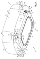
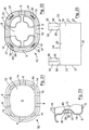
- the basin 2 comprises a base 5 and a peripheral wall 6 extending around the base 5, and in a generally upward direction from the base 5.
- the peripheral wall 6 in this embodiment of the invention comprises a pair of spaced apart side walls 8 which are joined by spaced apart end walls 9.
- the side walls 8 and end walls 9 define four radiused corners 10 of the peripheral wall 6.
- the side and end walls 8 and 9 together with the base 5 define a hollow interior region 12 which is lined by the liner 3, and an exterior surface 13 of the basin 2.
- the side and end walls 8 and 9 terminate in an upper peripheral edge 14 which defines an open mouth 15 to the hollow interior region 12.
- the upper peripheral edge 14 is radiused to accommodate the liner 3 being folded over the side and end walls 8 and 9, as will be described in more detail below.
- the liner 3 is of a water impermeable flexible plastics material, in this embodiment of the invention low density polyethylene material, which can withstand temperatures up to 106°F, and comprises an antimicrobial additive which is similar to the antimicrobial additive of the plastics material of the basin 2.
- the liner 3 is formed by blow moulding and is of film thickness of approximately 50 microns.
- the liner 3 is provided in a roll (not shown) of liners 3 which are separated from each other by respective lines of perforations (not shown) as will be well understood by those skilled in the art.
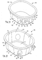
- each of the liners 3 is formed to have a base 18, and a peripheral wall 19, which when the liner 3 is erected extends around and generally upwardly from the base 18.
- the peripheral wall 19 forms a pair of spaced apart side walls 20 which are joined by a pair of spaced apart end walls 21.
- the side and end walls 20 and 21 define with the base 18 a hollow interior region 23, and the side and end walls 20 and 21 extend generally upwardly from the base 18 and terminate in the upper peripheral edge 24 of the liner 3, which defines an open mouth 25 to the hollow interior region 23.
- the base 18 of the liner 3 is of area which is substantially similar to the inner area of the base 5 of the basin 2, and the circumferential length of the peripheral wall 19 of the liner 3 is substantially similar to the circumferential length of the peripheral wall 6 of the basin 2.
- the side and end walls 20 and 21 define radiused corners 27 of the peripheral wall 19 of the liner 3, which when the liner 3 is placed in the hollow interior region 12 of the basin 2 with the base 18 of the liner 3 abutting and aligned with the base 5 of the basin 2, the corners 27 of the liner 3 substantially coincide with the corners 10 of the basin 2 and are aligned with and abut the corners 10 of the basin 2.
- the side and end walls 20 and 21 of the liner 3 are of substantially similar lengths to the lengths of the side and end walls 8 and 9, respectively, of the basin 2, so that when the base 18 of the liner 3 is in alignment with and abutting the base 5 of the basin 2, the side and end walls 20 and 21 of the liner 3 abut and are substantially aligned with the side and end walls 8 and 9 of the basin 2.
- the height of the side and end walls 20 and 21 from the base 18 of the liner 3 is approximately twice the height of the side and end walls 8 and 9 from the base 5 of the basin 2, so that the side and end walls 20 and 21 of the liner 3 can be folded over the radiused upper peripheral edge 14 of the basin 2 to extend downwardly over most of the exterior surface 13 of the side and end walls 8 and 9 of the basin 2, in order to cover most of the exterior surface 13 of the side and end walls 8 and 9.
- engagement openings 30 extend through and are equi-spaced apart around the peripheral wall 19 of the liner 3 adjacent but spaced apart from the upper peripheral edge 24 of the peripheral wall 19 for releasably securing the liner 3 to the basin 2 as will be described below.
- the engagement openings 30 are located in the peripheral wall 19 of the liner 3 adjacent the respective corners 27 of the peripheral wall 19, and are spaced apart downwardly from the upper peripheral edge 24 of the peripheral wall 19 with portions 32 of the peripheral wall 19 located between the upper peripheral edge 24 of the peripheral wall 19 and the respective engagement openings 30.
- the openings 30 are of an oval shape.
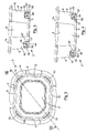
- the basin 2 comprises four spaced apart retaining means, namely, four retaining members 35 extending downwardly from the outer surface 13 of the peripheral wall 6 of the basin 2 adjacent the respective corners 10 of the peripheral wall 6 for releasably engaging the engagement openings 30 in the liner 3 for releasably securing and retaining the liner 3 to the basin 2 with the liner 3 lining the hollow interior region 12 of the basin 2.
- Four retaining member accommodating recesses 37 are formed into the exterior surface 13 of the peripheral wall 6 adjacent the corners 10 of the peripheral wall 6.
- the retaining member accommodating recesses 37 are located in the peripheral wall 6 adjacent the base 5 of the basin 2, and also extend into the base 5 of the basin 2 adjacent the corners 10.
- Each retaining member 35 extends from the exterior surface 13 of the peripheral wall 6 in the corresponding retaining member accommodating recess 37 and extends downwardly in the retaining member accommodating recess 37 to terminate in a distal end 38.
- Each retaining member 35 defines a gap 40 between itself and a portion 39 of the exterior surface 13 of the basin 2 within the retaining member accommodating recess 37 for accommodating the portion 32 of the peripheral wall 19 of the liner 3 between a corresponding one of the engagement openings 30 and the upper peripheral edge 24 of the peripheral wall 19 of the liner 3.
- Co-operating spaced apart parallel elongated tooth elements extend into each gap 40 from the corresponding retaining member 35 and the corresponding portion 39 of the exterior surface 13 in the corresponding retaining member accommodating recess 37, namely, first tooth elements 42 which extend from the retaining members 35 and second tooth elements 44 which extend from the portions 39 of the exterior surface 13 in the retaining member accommodating recesses 37.
- two of the parallel spaced apart elongated first tooth elements 42 extend longitudinally along each retaining member 35 into the gap 40 towards the portion 39 of the exterior surface 13 within the corresponding retaining member accommodating recess 37 and terminate short of the portion 39 of the exterior surface 13.
- Three of the spaced apart parallel elongated second tooth elements 44 extend from the portion 39 of the exterior surface 13 within each retaining member accommodating recess 37 towards the corresponding retaining member 35 and terminate short of the corresponding retaining member 35.
- the first and second tooth elements 42 and 44 of each retaining member 35 and the corresponding retaining member accommodating recess 37 are located relative to each other, with the first tooth elements 42 extending between the second tooth elements 44, and with each first tooth element 42 equi-spaced apart from an adjacent pair of the second tooth elements 44, so that the first and second tooth elements 42 and 44 co-operate with each other to securely but releasably engage the corresponding portions 32 of the peripheral wall 19 of the liner 3 when the engagement openings 30 are engaged with the corresponding retaining members 35.
- the retaining members 35 and the first and second tooth elements 42 and 44 are of similar material to that of the basin 2 and are integrally formed in one piece with the basin 2.
- the capacity of the basin 2 is approximately 7 litres.
- the basin 2 is substantially rectangular in plan view of internal length of approximately 320mm, of internal width of approximately 270mm, and the internal height of the peripheral wall 6 is approximately 145mm.
- the dimensions of the liner 3 substantially correspond with the internal dimensions of the basin 2, with the exception that the height of the peripheral wall 19 of the liner 3 is approximately twice the height of the peripheral wall 6 of the basin 2.
- one of the liners 3 is detached from the roll (not shown) of the liners 3, and is erected to form the base 18 and the side and end walls 20 and 21.
- the liner 3 is then placed in the hollow interior region 12 of the basin 2 with the base 18 of the liner 3 abutting and aligned with the base 5 of the basin 2, and with the side and end walls 20 and 21 of the liner 3 abutting and aligned with the side end walls 8 and 9, respectively, of the basin 2.
- peripheral wall 19 of the liner 3 is then folded downwardly over the radiused upper peripheral edge 14 of the peripheral wall 6 of the basin 2, so that the portion of the peripheral wall 19 which is folded down over the upper peripheral edge 14 of the peripheral wall 6 of the basin 2 is located exteriorly of the basin 2 covering most of the exterior surface 13 of the peripheral wall 6 of the basin 2.
- the portions 32 of the peripheral wall 19 of the liner 3 adjacent the engagement openings 30 are then pulled further downwardly to clear the distal ends 38 of the corresponding retaining members 35, and the retaining members 35 are engaged in the engagement openings 30 with the corresponding portions 32 of the peripheral wall 19 of the liner 3 engaged between the first and second tooth elements 42 and 44, respectively, in the gaps 40 between the corresponding retaining members 35 and the portion 39 of the exterior surface 13 of the retaining member accommodating recesses 37.
- the apparatus 1 with the liner 3 located in the hollow interior region 12 of the basin 2 and secured to the basin 2 by the retaining members 35 engaging the corresponding engagement openings 30 of the liner 3 is ready for use.
- the liner 3 in the basin 2 is charged with water, and the patient is then washed with the water.
- the water is emptied from the liner 3, and the liner 3 is disengaged from the basin 2 by disengaging the engagement openings 30 from the retaining members 35.
- the liner 3 is then removed from the basin 2 for disposal. If a person washing the patient is wearing disposable gloves, once the engagement openings 30 are disengaged from the retaining members 35, the disposable gloves are placed in the liner 3 prior to removal from the basin 2, and as the liner 3 is being removed from the basin 2, the disposable gloves are wrapped in the liner 3, which is then disposed of.
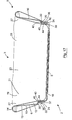
- FIG. 50 there is illustrated apparatus according to another embodiment of the invention, indicated generally by the reference numeral 50, for washing a patient.
- the apparatus 50 is substantially similar to the apparatus 1 and similar components are identified by the same reference numerals.
- the apparatus 50 comprises a basin 52 which is substantially similar to the basin 2 of the apparatus 1, and a liner 53 which is also substantially similar to the liner 3 of the apparatus 1.
- the main difference between the basin 52 of the apparatus 50 and the basin 2 of the apparatus 1 is that the retaining member accommodating recesses 37 are located in the peripheral wall 6 of the basin 52 at a level above the base 5 of the basin 52 which is greater than the level at which the retaining member accommodating recesses 37 are located in the peripheral wall 6 of the basin 2. Additionally, the retaining members 35 are likewise located at a higher level in the peripheral wall 6 of the basin 52 than those in the peripheral wall 6 of the basin 1. Additionally, first and second tooth elements are omitted from the retaining members 35 and the corresponding retaining member accommodating recesses 37 in the basin 52. Otherwise, the basin 52 is substantially similar to the basin 2 of the apparatus 1.
- the height of the peripheral wall 19 of the liner 53 is shorter than the height of the peripheral wall 19 of the liner 3 of the apparatus 1.
- the height of the peripheral wall 19 of the liner 53 is approximately one and a half times the height of the peripheral wall 6 of the basin 52.
- the engagement openings 30 in the liner 53 are formed by respective loops 55 which extend from the upper peripheral edge 24 of the peripheral wall 19 of the liner 53 at spaced apart locations 56 adjacent the corners 27 to define with the upper peripheral edge 24 of the peripheral wall 19 between the locations 56 the corresponding engagement openings 30.
- the loops 55 are of material similar to the material of the liner 53 and are integrally formed in one piece with the liner 53. Otherwise, the liner 53 is similar to the liner 3 of the apparatus 1.
- the materials of the basin 52 and the liner 53 are similar to the materials of the basin 2 and the liner 3, respectively, of the apparatus 1.
- the liner 53 is placed in the hollow interior region 12 of the basin 52 with the base 18 of the liner 53 abutting and aligned with the base 5 of the basin 52.
- the side and end walls 20 and 21 of the liner 53 are also located abutting and aligned with the side and end walls 8 and 9 of the basin 52.
- the peripheral wall 19 of the liner 53 is then folded downwardly over the upper peripheral edge 14 of the peripheral wall 6 of the basin 52, and the loops 55 are stretched downwardly below the distal ends 38 of the corresponding retaining members 35 of the basin 52 for engaging the retaining members 35 in the engagement openings 30 with the loops 55 engaged in the gap 40 between the corresponding retaining members 35 and the portions 39 of the exterior surface 13 in the retaining member accommodating recesses 37.
- basins have been described as being of a particular size, shape and capacity and of particular materials, the basins may be of any size, shape or capacity, and may be of any other suitable materials, be the material a plastics material or otherwise, and may be formed by any other suitable forming process.
- the liners have been described as being of a particular size, shape and capacity, it will be readily apparent to those skilled in the art that the liners may be of any other suitable size, shape and capacity, and in general, the liners typically will be of a shape which substantially corresponds to that of the corresponding basin.
- liners have been described as being of particular materials, it will be readily apparent to those skilled in the art that the liners may be of any other suitable material or materials, and formed by any suitable process.
- any number of engagement openings and retaining means may be provided, and indeed, in certain cases, it is envisaged that two engagement openings and two corresponding retaining means may be sufficient. It will also be appreciated that the retaining means and the engagement openings may be provided at locations other than corner locations.
- basins and the liners have been described for use in washing or bathing a patient in bed, the basins and liners may be used for any other purpose, and are particularly suitable for use where one wishes to eliminate or at least minimise the transfer of infections, diseases and the like.
- the materials of the liners and the basins have been described as comprising an antimicrobial additive, it is envisaged that in certain cases, the antimicrobial additive may be omitted. However, it will be appreciated that it would be desirable to at least provide the liner material with an antimicrobial additive, although this, while it would be desirable, is not essential. Needless to say, other antimicrobial additives instead of the antimicrobial additive described may be used in either or both the basin and the liner.
- the basin may be of any other suitable capacity and other suitable dimensions.
- the capacity of the basin would lie in the range of 3 to 7 litres, and in general, in the range of 4 to 5 litres.
- the internal length of the basin would range from 250mm to 400mm, and the internal width of the basin would range from 200mm to 350mm.
- the internal height of the basin in other words, the internal height of the peripheral wall of the basin from the base to the upper peripheral edge thereof would lie in the range of 100mm to 250mm.
Landscapes
- Health & Medical Sciences (AREA)
- Public Health (AREA)
- Nursing (AREA)
- Life Sciences & Earth Sciences (AREA)
- Animal Behavior & Ethology (AREA)
- General Health & Medical Sciences (AREA)
- Veterinary Medicine (AREA)
- Engineering & Computer Science (AREA)
- Mechanical Engineering (AREA)
- Sink And Installation For Waste Water (AREA)
- Apparatus For Disinfection Or Sterilisation (AREA)
- Sewage (AREA)
- Housing For Livestock And Birds (AREA)
Claims (15)
- Becken mit einer Basis (5) und einer Umfangswand (6), die sich um die Basis (5) herum und in einer allgemein aufwärts verlaufenden Richtung von der Basis (5) erstreckt und in einem oberen Umfangsrand (14) endet, wobei die Basis (5) und die Umfangswand (6) einen hohlen Innenbereich (12) und eine Außenfläche (13) festlegen, wobei der obere Umfangsrand (14) der Umfangswand (6) einen offenen Zugang (15) zu dem hohlen Innenbereich (12) bildet, und mit einer Halteeinrichtung (35), die an dem Becken zum lösbaren in Eingriff kommen mit und Halten einer Auskleidung (3, 53) angeordnet ist, welche den hohlen Innenbereich (12) des Beckens auskleidet, wobei zumindest zwei Halteeinrichtungen (35) vorhanden sind, jede Halteeinrichtung (35) an der Außenfläche (13) des Beckens angeordnet ist und ein Haltebauteil (35) aufweist, das sich von der Außenfläche (13) des Beckens nach unten erstreckt, und wobei jedes Haltebauteil (35) in einem von der Außenfläche (13) des Beckens beabstandeten distalen Ende (38) endet,
dadurch gekennzeichnet, dass das Haltebauteil (35) sich in eine zugehörige, in der Umfangswand (6) ausgebildete Haltebauteilaufnahmeaussparung (37) erstreckt. - Becken nach Anspruch 1,
dadurch gekennzeichnet, dass jedes Haltebauteil (35) zusammen mit der Außenfläche (13) des Beckens dazwischen einen Spalt (40) zur Aufnahme eines Teils (32) der Auskleidung (3, 35) darin bildet. - Becken nach Anspruch 2,
dadurch gekennzeichnet, dass zumindest ein Zackenelement (42, 44) sich von jedem der Haltebauteile (35) oder der jedem Haltebauteil (35) benachbarten Außenfläche (13) des Beckens in den Spalt (40) in Richtung auf das andere des entsprechenden Haltebauteils (35) oder der Außenfläche (13) des Beckens erstreckt, wobei jedes Zackenelement (42, 44) knapp vor dem anderen des zugehörigen Haltebauteils (35) oder der Außenfläche (13) des Beckens endet, um den entsprechenden Teil (32) der Auskleidung (3, 53) lösbar dazwischen zu halten. - Becken nach Anspruch 3,
dadurch gekennzeichnet, dass sich zumindest ein Zackenelement (42) von jedem der Haltebauteile (35) erstreckt und sich zumindest ein Zackenelement (44) von der den Haltebauteilen (35) benachbarten Außenfläche (13) des Beckens erstreckt, wobei die Zackenelemente (42, 44), die sich von der zugehörigen Außenseite (13) des Beckens benachbart jedem der Haltebauteile (35) erstrecken, und die zugehörigen Haltebauteile (35) miteinander zum lösbaren Halten des entsprechenden Teils (32) der Auskleidung (3, 53) dazwischen zusammenwirken. - Becken nach Anspruch 3 oder 4,
dadurch gekennzeichnet, dass die Anzahl der Zackenelemente (42, 44), die sich von der Außenfläche (13) des Beckens benachbart jedem der Haltebauteile (35) erstreckt, und die Anzahl von Zackenelementen (42, 44), die sich von dem zugehörigen Haltebauteil (35) erstreckt, sich um ein Zackenelement (42, 44) unterscheidet, und dass das zumindest eine Zackenelement (42, 44), das sich von der jedem Haltebauteil (35) benachbarten Außenseite (13) des Beckens oder dem zugehörigen Haltebauteil (35) mit der geringsten Zahl von Zackenelementen (42, 44) erstreckt, zwischen den Zackenelementen (42, 44) verläuft, die sich von dem anderen der Außenfläche (13) des Beckens und dem Haltebauteil (35) erstrecken. - Becken nach einem der Ansprüche 3 bis 5,
dadurch gekennzeichnet, dass jedes Haltebauteil (35) sich von dem Becken in die zugehörige Haltebauteilaufnahmeaussparung (37) erstreckt. - Becken nach einem der vorhergehenden Ansprüche,
dadurch gekennzeichnet, dass die Umfangswand (6) des Beckens ein Paar voneinander beabstandete Seitenwände (8) aufweist, die sich von der Basis (5) nach oben erstrecken, und ein Paar voneinander beabstandeter Stirnwände (9), die sich von der Basis (5) nach oben erstrecken und die Seitenwände (8) verbinden, wobei die Seiten- und Stirnwände (8, 9) Ecken (10) der Umfangswand (6) bilden und jedes Haltebauteil (35) benachbart einer zugehörigen der Ecken (10) der Umfangswand (6) angeordnet ist. - Becken nach einem der vorhergehenden Ansprüche,
dadurch gekennzeichnet, dass das Becken ein Kunststoffmaterial und ein antimikrobielles Additiv umfasst, welches während eines Spritzgießverfahrens zum Formen des Beckens mit dem Kunststoffmaterial vermischt wird. - Vorrichtung zum Waschen eines Patienten, wobei die Vorrichtung das Becken (2, 52) nach einem der vorhergehenden Ansprüche und eine den hohlen Innenbereich (12) des Beckens (2, 52) auskleidende Auskleidung (3, 53) umfasst, wobei die Auskleidung (3, 53) wenigstens zwei voneinander beabstandete Eingriffsöffnungen (30) aufweist, die lösbar mit den zugehörigen Haltebauteilen (35) des Beckens (2, 52) in Eingriff sind.
- Vorrichtung nach Anspruch 9,
dadurch gekennzeichnet, dass die Auskleidung (3, 53) eine Umfangswand (19) umfasst, die an einem Ende (18) dichtend verschlossen ist und einen hohlen Innenbereich (23) der Auskleidung (3, 53) festlegt, wobei die Umfangswand (19) an ihrem anderen Ende in einem Umfangsrand (24) endet, der einen offenen Zugang (25) zu dem hohlen Innenbereich (23) der Auskleidung (3, 53) festlegt, wobei die Umfangswand (9) der Auskleidung (3, 53) nach unten über eine Umfangswand (6) des Beckens (2, 52) faltbar ist und die Eingriffsöffnungen (30) zum lösbaren in Eingriff kommen mit den zugehörigen Haltebauteilen (35) des Beckens (2, 52) angeordnet sind, wenn die Umfangswand (19) der Auskleidung (3, 53) über die Umfangswand (6) des Beckens (2, 52) nach unten gefaltet ist. - Vorrichtung nach Anspruch 10,
dadurch gekennzeichnet, dass jede Eingriffsöffnung (30) sich benachbart dem Umfangsrand (24) der Umfangswand (19) der Auskleidung (3, 53) befindet. - Vorrichtung nach Anspruch 10 oder 11,
dadurch gekennzeichnet, dass jede Eingriffsöffnung (30) sich in der Umfangswand (19) der Auskleidung (3, 53) benachbart dem Umfangsrand (24) derselben befindet, jedoch von ihrem Umfangsrand (24) beabstandet. - Vorrichtung nach Anspruch 10 oder 11,
dadurch gekennzeichnet, dass jede Eingriffsöffnung (30) durch eine Schlaufe (55) aus Material gebildet ist, die von dem Umfangsrand (24) der Auskleidung (3, 53) an voneinander beabstandeten Stellen (56) und dem Umfangsrand (24) der Auskleidung (3, 53) zwischen den voneinander beabstandeten Stellen (56) verläuft, von denen sich die Materialschlaufe (55) erstreckt. - Vorrichtung nach einem der Ansprüche 10 bis 13,
dadurch gekennzeichnet, dass die Auskleidung (3, 53) eine Basis (18) aufweist und die Umfangswand (19) der Auskleidung (3, 53) sich um die Basis (18) herum und allgemein nach oben erstreckt, wobei die Basis (18) dazu ausgeführt ist, eine Innenfläche der Basis (5) des Beckens (2, 52) auszukleiden, und die Umfangswand (19) der Auskleidung (3, 53) dazu ausgeführt ist, eine Innenfläche der Umfangswand (6) des Beckens (2, 52) auszukleiden. - Vorrichtung nach einem der Ansprüche 10 bis 14,
dadurch gekennzeichnet, dass die Umfangswand (19) der Auskleidung (3, 53) ein Paar voneinander beabstandeter Seitenwände (20) umfasst, die sich von der Basis (18) der Auskleidung (3, 53) aufwärts erstrecken und durch ein Paar voneinander beabstandeter Stirnwände (21) verbunden sind, die sich von der Basis (18) der Auskleidung (3, 53) nach oben erstrecken, wobei die Seiten- und Stirnwände (20, 21) der Auskleidung (3, 53) zusammen mit der Basis (18) derselben den hohlen Innenbereich (23) der Auskleidung (3, 53) festlegen, die Seiten- und Stirnwände (20, 21) der Auskleidung (3, 53) den oberen Umfangsrand (24) der Umfangswand (19) der Auskleidung (3, 53) festlegen, und die Seiten- und Stirnwände (20, 21) der Auskleidung (3, 53) Ecken (27) der Umfangswand (19) der Auskleidung (3, 53) festlegen, und wobei jede Eingriffsöffnung (30) sich benachbart einer zugehörigen der Ecken (27) der Umfangswand (19) der Auskleidung (3, 53) befindet.
Priority Applications (1)
| Application Number | Priority Date | Filing Date | Title |
|---|---|---|---|
| EP17197805.9A EP3300646B1 (de) | 2012-12-04 | 2013-12-04 | Becken, verkleidung zum auskleiden eines beckens und verfahren zur bereitstellung eines beckens zum waschen eines patienten |
Applications Claiming Priority (3)
| Application Number | Priority Date | Filing Date | Title |
|---|---|---|---|
| IES20120524 | 2012-12-04 | ||
| IES20130339 | 2013-11-05 | ||
| PCT/IE2013/000026 WO2014087391A1 (en) | 2012-12-04 | 2013-12-04 | Apparatus securing a liner to a basin and a corresponding method for washing a patient |
Related Child Applications (2)
| Application Number | Title | Priority Date | Filing Date |
|---|---|---|---|
| EP17197805.9A Division EP3300646B1 (de) | 2012-12-04 | 2013-12-04 | Becken, verkleidung zum auskleiden eines beckens und verfahren zur bereitstellung eines beckens zum waschen eines patienten |
| EP17197805.9A Division-Into EP3300646B1 (de) | 2012-12-04 | 2013-12-04 | Becken, verkleidung zum auskleiden eines beckens und verfahren zur bereitstellung eines beckens zum waschen eines patienten |
Publications (2)
| Publication Number | Publication Date |
|---|---|
| EP2931099A1 EP2931099A1 (de) | 2015-10-21 |
| EP2931099B1 true EP2931099B1 (de) | 2018-04-25 |
Family
ID=49817138
Family Applications (2)
| Application Number | Title | Priority Date | Filing Date |
|---|---|---|---|
| EP13811011.9A Not-in-force EP2931099B1 (de) | 2012-12-04 | 2013-12-04 | Vorrichtung zu befestigen eines liners an einem becken zum washen eines patienten |
| EP17197805.9A Not-in-force EP3300646B1 (de) | 2012-12-04 | 2013-12-04 | Becken, verkleidung zum auskleiden eines beckens und verfahren zur bereitstellung eines beckens zum waschen eines patienten |
Family Applications After (1)
| Application Number | Title | Priority Date | Filing Date |
|---|---|---|---|
| EP17197805.9A Not-in-force EP3300646B1 (de) | 2012-12-04 | 2013-12-04 | Becken, verkleidung zum auskleiden eines beckens und verfahren zur bereitstellung eines beckens zum waschen eines patienten |
Country Status (5)
| Country | Link |
|---|---|
| US (2) | US9888814B2 (de) |
| EP (2) | EP2931099B1 (de) |
| AU (1) | AU2013353633B2 (de) |
| CA (1) | CA2926776A1 (de) |
| WO (1) | WO2014087391A1 (de) |
Families Citing this family (5)
| Publication number | Priority date | Publication date | Assignee | Title |
|---|---|---|---|---|
| US11406227B2 (en) | 2016-04-10 | 2022-08-09 | Catapult Products, Llc | Neonatal bath tub with stabilizing backrest |
| USD786570S1 (en) * | 2016-04-10 | 2017-05-16 | Catapult Products, Llc | Infant bath tub |
| CN111671351A (zh) * | 2020-05-22 | 2020-09-18 | 邱鑫 | 一种可遮挡的医用坐便椅 |
| USD987190S1 (en) * | 2022-08-12 | 2023-05-23 | Foshan Bomacy Beauty Equipment Company | Disposable tub liner |
| US20250134766A1 (en) * | 2023-10-27 | 2025-05-01 | Venessa Brunt | Bathing Apparatus and Method of Using the Same |
Family Cites Families (18)
| Publication number | Priority date | Publication date | Assignee | Title |
|---|---|---|---|---|
| US3128904A (en) * | 1964-04-14 | Container and readily removable liners therefor | ||
| DE2020978A1 (de) * | 1970-04-29 | 1971-11-18 | Rainer Schubert | Auskleidung fuer offene,mit Abfluessen versehene Behaeltnisse,insbesondere Badewannen |
| US4027774A (en) * | 1975-07-22 | 1977-06-07 | Cote Leopold J | Rubbish container |
| DE2642823A1 (de) * | 1976-09-23 | 1978-03-30 | Wolfgang Brall | Badewanneneinsatz |
| US4106133A (en) * | 1977-05-09 | 1978-08-15 | Roberts Thomas J | Contamination prevention device for sitz bath |
| DE3046628C2 (de) * | 1980-12-11 | 1983-03-03 | Paul A-5020 Salzburg Haslauer | Vorrichtung zum Verabreichen von Peloid-Voll- oder Sitzbädern |
| US4664347A (en) * | 1985-07-22 | 1987-05-12 | Brown Brian A | Trash basket having integral, internally-flush vanes for supporting plastic grocery bags |
| US5100087A (en) * | 1989-03-06 | 1992-03-31 | Ashby Stephen B | Fastening device for container liners |
| US5261553A (en) * | 1988-01-07 | 1993-11-16 | Jay Mueller | Fastening device for container liners |
| US5040252A (en) * | 1989-10-04 | 1991-08-20 | Taggart John F | Bathtub cover |
| US5611507A (en) * | 1995-05-15 | 1997-03-18 | Smith; Jimmy R. | Secure bag holding device |
| JP2001270049A (ja) * | 2000-03-28 | 2001-10-02 | Sumitomo Chem Co Ltd | 抗菌性を有する樹脂成形体 |
| US6772800B1 (en) | 2003-01-23 | 2004-08-10 | Maria Garcia | Pedicure basin liner system |
| US7243811B1 (en) * | 2005-08-11 | 2007-07-17 | Pressix Technologies, Llc | Trashcan assembly including bag engaging member |
| FR2900559B1 (fr) * | 2006-05-02 | 2008-06-27 | Amerouche Bousselat | Enveloppe jetable destinee a proteger les lavabos et eviers des salissures provoquees notamment lors de la teinture des cheveux |
| US20080116205A1 (en) * | 2006-11-22 | 2008-05-22 | Forest Robert A | Trash receptacle |
| US20090126320A1 (en) * | 2007-11-16 | 2009-05-21 | Playtex Products, Inc. | Waste disposal devices and methods |
| US20130232923A1 (en) * | 2012-03-09 | 2013-09-12 | Gabriel D. Beversluis | Bag recycler and holder |
-
2013
- 2013-12-04 EP EP13811011.9A patent/EP2931099B1/de not_active Not-in-force
- 2013-12-04 AU AU2013353633A patent/AU2013353633B2/en not_active Ceased
- 2013-12-04 US US14/648,832 patent/US9888814B2/en not_active Expired - Fee Related
- 2013-12-04 WO PCT/IE2013/000026 patent/WO2014087391A1/en not_active Ceased
- 2013-12-04 CA CA2926776A patent/CA2926776A1/en not_active Abandoned
- 2013-12-04 EP EP17197805.9A patent/EP3300646B1/de not_active Not-in-force
-
2017
- 2017-12-20 US US15/848,112 patent/US20180110378A1/en not_active Abandoned
Non-Patent Citations (1)
| Title |
|---|
| None * |
Also Published As
| Publication number | Publication date |
|---|---|
| AU2013353633A1 (en) | 2015-07-23 |
| AU2013353633B2 (en) | 2018-12-20 |
| US20180110378A1 (en) | 2018-04-26 |
| EP3300646B1 (de) | 2022-06-29 |
| US9888814B2 (en) | 2018-02-13 |
| WO2014087391A1 (en) | 2014-06-12 |
| EP2931099A1 (de) | 2015-10-21 |
| US20150342417A1 (en) | 2015-12-03 |
| EP3300646A1 (de) | 2018-04-04 |
| CA2926776A1 (en) | 2014-06-12 |
Similar Documents
| Publication | Publication Date | Title |
|---|---|---|
| US20180110378A1 (en) | Apparatus securing a liner to a basin and a corresponding method for washing a patient | |
| US8690848B2 (en) | Closure for ostomy pouch and method thereof | |
| US9149402B2 (en) | Cover for patient transfer devices | |
| JP7390375B2 (ja) | 医療機器の封じ込め輸送システム及び方法 | |
| US20120317722A1 (en) | Changing Table Cover | |
| US11696811B2 (en) | Medical device transportation systems | |
| US20210186641A1 (en) | Medical device transportation systems | |
| US20120008877A1 (en) | Bag with sealing device and collar for disposing of waste | |
| KR101646091B1 (ko) | 교환이 용이한 환자용 매트리스 시트 | |
| JP2017526491A (ja) | ユーザーの尿及び糞便を回収する用具 | |
| AU2008286679A1 (en) | A bag with sealing device and collar for disposing of waste | |
| ITUD20090207A1 (it) | Dispositivo per il trasporto di strumenti medicali | |
| CN101212942A (zh) | 用于处置身体废料的接收器和方法 | |
| CN206424255U (zh) | 新生儿护理车 | |
| CN201399061Y (zh) | 一种卧床病人用便盆 | |
| WO2017197183A1 (en) | Protective device and method for the underside of a carryall | |
| WO2017068566A1 (en) | A bag and a bedpan sanitary bag, and a method for minimising aerosolisation of pathogens from human excrement | |
| CN211932923U (zh) | 一种带随箱盆的旅行箱 | |
| CN204617135U (zh) | 医用服装 | |
| US20130042401A1 (en) | Apparatus, system and method for transporting a potty seat | |
| AU2014101599A4 (en) | Collapsible bowl | |
| AU2007100785A4 (en) | Waste container with sealing device | |
| CN207912804U (zh) | 一种卧床患者饮食护理巾 | |
| CN206372313U (zh) | 一种消毒盒 | |
| GB2532409A (en) | A disposable commode pan |
Legal Events
| Date | Code | Title | Description |
|---|---|---|---|
| PUAI | Public reference made under article 153(3) epc to a published international application that has entered the european phase |
Free format text: ORIGINAL CODE: 0009012 |
|
| 17P | Request for examination filed |
Effective date: 20150624 |
|
| AK | Designated contracting states |
Kind code of ref document: A1 Designated state(s): AL AT BE BG CH CY CZ DE DK EE ES FI FR GB GR HR HU IE IS IT LI LT LU LV MC MK MT NL NO PL PT RO RS SE SI SK SM TR |
|
| AX | Request for extension of the european patent |
Extension state: BA ME |
|
| DAX | Request for extension of the european patent (deleted) | ||
| GRAP | Despatch of communication of intention to grant a patent |
Free format text: ORIGINAL CODE: EPIDOSNIGR1 |
|
| STAA | Information on the status of an ep patent application or granted ep patent |
Free format text: STATUS: GRANT OF PATENT IS INTENDED |
|
| INTG | Intention to grant announced |
Effective date: 20170222 |
|
| GRAJ | Information related to disapproval of communication of intention to grant by the applicant or resumption of examination proceedings by the epo deleted |
Free format text: ORIGINAL CODE: EPIDOSDIGR1 |
|
| STAA | Information on the status of an ep patent application or granted ep patent |
Free format text: STATUS: REQUEST FOR EXAMINATION WAS MADE |
|
| GRAS | Grant fee paid |
Free format text: ORIGINAL CODE: EPIDOSNIGR3 |
|
| STAA | Information on the status of an ep patent application or granted ep patent |
Free format text: STATUS: GRANT OF PATENT IS INTENDED |
|
| GRAP | Despatch of communication of intention to grant a patent |
Free format text: ORIGINAL CODE: EPIDOSNIGR1 |
|
| INTC | Intention to grant announced (deleted) | ||
| INTG | Intention to grant announced |
Effective date: 20171117 |
|
| GRAA | (expected) grant |
Free format text: ORIGINAL CODE: 0009210 |
|
| STAA | Information on the status of an ep patent application or granted ep patent |
Free format text: STATUS: THE PATENT HAS BEEN GRANTED |
|
| AK | Designated contracting states |
Kind code of ref document: B1 Designated state(s): AL AT BE BG CH CY CZ DE DK EE ES FI FR GB GR HR HU IE IS IT LI LT LU LV MC MK MT NL NO PL PT RO RS SE SI SK SM TR |
|
| REG | Reference to a national code |
Ref country code: GB Ref legal event code: FG4D |
|
| REG | Reference to a national code |
Ref country code: CH Ref legal event code: EP |
|
| REG | Reference to a national code |
Ref country code: AT Ref legal event code: REF Ref document number: 991942 Country of ref document: AT Kind code of ref document: T Effective date: 20180515 |
|
| REG | Reference to a national code |
Ref country code: IE Ref legal event code: FG4D |
|
| REG | Reference to a national code |
Ref country code: DE Ref legal event code: R096 Ref document number: 602013036596 Country of ref document: DE |
|
| REG | Reference to a national code |
Ref country code: NL Ref legal event code: FP |
|
| REG | Reference to a national code |
Ref country code: LT Ref legal event code: MG4D |
|
| PG25 | Lapsed in a contracting state [announced via postgrant information from national office to epo] |
Ref country code: NO Free format text: LAPSE BECAUSE OF FAILURE TO SUBMIT A TRANSLATION OF THE DESCRIPTION OR TO PAY THE FEE WITHIN THE PRESCRIBED TIME-LIMIT Effective date: 20180725 Ref country code: FI Free format text: LAPSE BECAUSE OF FAILURE TO SUBMIT A TRANSLATION OF THE DESCRIPTION OR TO PAY THE FEE WITHIN THE PRESCRIBED TIME-LIMIT Effective date: 20180425 Ref country code: PL Free format text: LAPSE BECAUSE OF FAILURE TO SUBMIT A TRANSLATION OF THE DESCRIPTION OR TO PAY THE FEE WITHIN THE PRESCRIBED TIME-LIMIT Effective date: 20180425 Ref country code: BG Free format text: LAPSE BECAUSE OF FAILURE TO SUBMIT A TRANSLATION OF THE DESCRIPTION OR TO PAY THE FEE WITHIN THE PRESCRIBED TIME-LIMIT Effective date: 20180725 Ref country code: LT Free format text: LAPSE BECAUSE OF FAILURE TO SUBMIT A TRANSLATION OF THE DESCRIPTION OR TO PAY THE FEE WITHIN THE PRESCRIBED TIME-LIMIT Effective date: 20180425 Ref country code: ES Free format text: LAPSE BECAUSE OF FAILURE TO SUBMIT A TRANSLATION OF THE DESCRIPTION OR TO PAY THE FEE WITHIN THE PRESCRIBED TIME-LIMIT Effective date: 20180425 Ref country code: SE Free format text: LAPSE BECAUSE OF FAILURE TO SUBMIT A TRANSLATION OF THE DESCRIPTION OR TO PAY THE FEE WITHIN THE PRESCRIBED TIME-LIMIT Effective date: 20180425 |
|
| PG25 | Lapsed in a contracting state [announced via postgrant information from national office to epo] |
Ref country code: HR Free format text: LAPSE BECAUSE OF FAILURE TO SUBMIT A TRANSLATION OF THE DESCRIPTION OR TO PAY THE FEE WITHIN THE PRESCRIBED TIME-LIMIT Effective date: 20180425 Ref country code: RS Free format text: LAPSE BECAUSE OF FAILURE TO SUBMIT A TRANSLATION OF THE DESCRIPTION OR TO PAY THE FEE WITHIN THE PRESCRIBED TIME-LIMIT Effective date: 20180425 Ref country code: LV Free format text: LAPSE BECAUSE OF FAILURE TO SUBMIT A TRANSLATION OF THE DESCRIPTION OR TO PAY THE FEE WITHIN THE PRESCRIBED TIME-LIMIT Effective date: 20180425 Ref country code: GR Free format text: LAPSE BECAUSE OF FAILURE TO SUBMIT A TRANSLATION OF THE DESCRIPTION OR TO PAY THE FEE WITHIN THE PRESCRIBED TIME-LIMIT Effective date: 20180726 |
|
| REG | Reference to a national code |
Ref country code: AT Ref legal event code: MK05 Ref document number: 991942 Country of ref document: AT Kind code of ref document: T Effective date: 20180425 |
|
| PG25 | Lapsed in a contracting state [announced via postgrant information from national office to epo] |
Ref country code: PT Free format text: LAPSE BECAUSE OF FAILURE TO SUBMIT A TRANSLATION OF THE DESCRIPTION OR TO PAY THE FEE WITHIN THE PRESCRIBED TIME-LIMIT Effective date: 20180827 |
|
| REG | Reference to a national code |
Ref country code: DE Ref legal event code: R097 Ref document number: 602013036596 Country of ref document: DE |
|
| PG25 | Lapsed in a contracting state [announced via postgrant information from national office to epo] |
Ref country code: DK Free format text: LAPSE BECAUSE OF FAILURE TO SUBMIT A TRANSLATION OF THE DESCRIPTION OR TO PAY THE FEE WITHIN THE PRESCRIBED TIME-LIMIT Effective date: 20180425 Ref country code: SK Free format text: LAPSE BECAUSE OF FAILURE TO SUBMIT A TRANSLATION OF THE DESCRIPTION OR TO PAY THE FEE WITHIN THE PRESCRIBED TIME-LIMIT Effective date: 20180425 Ref country code: RO Free format text: LAPSE BECAUSE OF FAILURE TO SUBMIT A TRANSLATION OF THE DESCRIPTION OR TO PAY THE FEE WITHIN THE PRESCRIBED TIME-LIMIT Effective date: 20180425 Ref country code: CZ Free format text: LAPSE BECAUSE OF FAILURE TO SUBMIT A TRANSLATION OF THE DESCRIPTION OR TO PAY THE FEE WITHIN THE PRESCRIBED TIME-LIMIT Effective date: 20180425 Ref country code: AT Free format text: LAPSE BECAUSE OF FAILURE TO SUBMIT A TRANSLATION OF THE DESCRIPTION OR TO PAY THE FEE WITHIN THE PRESCRIBED TIME-LIMIT Effective date: 20180425 Ref country code: EE Free format text: LAPSE BECAUSE OF FAILURE TO SUBMIT A TRANSLATION OF THE DESCRIPTION OR TO PAY THE FEE WITHIN THE PRESCRIBED TIME-LIMIT Effective date: 20180425 |
|
| PG25 | Lapsed in a contracting state [announced via postgrant information from national office to epo] |
Ref country code: IT Free format text: LAPSE BECAUSE OF FAILURE TO SUBMIT A TRANSLATION OF THE DESCRIPTION OR TO PAY THE FEE WITHIN THE PRESCRIBED TIME-LIMIT Effective date: 20180425 Ref country code: SM Free format text: LAPSE BECAUSE OF FAILURE TO SUBMIT A TRANSLATION OF THE DESCRIPTION OR TO PAY THE FEE WITHIN THE PRESCRIBED TIME-LIMIT Effective date: 20180425 |
|
| PLBE | No opposition filed within time limit |
Free format text: ORIGINAL CODE: 0009261 |
|
| STAA | Information on the status of an ep patent application or granted ep patent |
Free format text: STATUS: NO OPPOSITION FILED WITHIN TIME LIMIT |
|
| 26N | No opposition filed |
Effective date: 20190128 |
|
| PG25 | Lapsed in a contracting state [announced via postgrant information from national office to epo] |
Ref country code: SI Free format text: LAPSE BECAUSE OF FAILURE TO SUBMIT A TRANSLATION OF THE DESCRIPTION OR TO PAY THE FEE WITHIN THE PRESCRIBED TIME-LIMIT Effective date: 20180425 |
|
| REG | Reference to a national code |
Ref country code: CH Ref legal event code: PL |
|
| PG25 | Lapsed in a contracting state [announced via postgrant information from national office to epo] |
Ref country code: LU Free format text: LAPSE BECAUSE OF NON-PAYMENT OF DUE FEES Effective date: 20181204 Ref country code: MC Free format text: LAPSE BECAUSE OF FAILURE TO SUBMIT A TRANSLATION OF THE DESCRIPTION OR TO PAY THE FEE WITHIN THE PRESCRIBED TIME-LIMIT Effective date: 20180425 |
|
| REG | Reference to a national code |
Ref country code: BE Ref legal event code: MM Effective date: 20181231 |
|
| PG25 | Lapsed in a contracting state [announced via postgrant information from national office to epo] |
Ref country code: BE Free format text: LAPSE BECAUSE OF NON-PAYMENT OF DUE FEES Effective date: 20181231 Ref country code: AL Free format text: LAPSE BECAUSE OF FAILURE TO SUBMIT A TRANSLATION OF THE DESCRIPTION OR TO PAY THE FEE WITHIN THE PRESCRIBED TIME-LIMIT Effective date: 20180425 |
|
| PG25 | Lapsed in a contracting state [announced via postgrant information from national office to epo] |
Ref country code: LI Free format text: LAPSE BECAUSE OF NON-PAYMENT OF DUE FEES Effective date: 20181231 Ref country code: CH Free format text: LAPSE BECAUSE OF NON-PAYMENT OF DUE FEES Effective date: 20181231 |
|
| PG25 | Lapsed in a contracting state [announced via postgrant information from national office to epo] |
Ref country code: MT Free format text: LAPSE BECAUSE OF NON-PAYMENT OF DUE FEES Effective date: 20181204 |
|
| PG25 | Lapsed in a contracting state [announced via postgrant information from national office to epo] |
Ref country code: TR Free format text: LAPSE BECAUSE OF FAILURE TO SUBMIT A TRANSLATION OF THE DESCRIPTION OR TO PAY THE FEE WITHIN THE PRESCRIBED TIME-LIMIT Effective date: 20180425 |
|
| PG25 | Lapsed in a contracting state [announced via postgrant information from national office to epo] |
Ref country code: MK Free format text: LAPSE BECAUSE OF NON-PAYMENT OF DUE FEES Effective date: 20180425 Ref country code: HU Free format text: LAPSE BECAUSE OF FAILURE TO SUBMIT A TRANSLATION OF THE DESCRIPTION OR TO PAY THE FEE WITHIN THE PRESCRIBED TIME-LIMIT; INVALID AB INITIO Effective date: 20131204 Ref country code: CY Free format text: LAPSE BECAUSE OF FAILURE TO SUBMIT A TRANSLATION OF THE DESCRIPTION OR TO PAY THE FEE WITHIN THE PRESCRIBED TIME-LIMIT Effective date: 20180425 |
|
| PG25 | Lapsed in a contracting state [announced via postgrant information from national office to epo] |
Ref country code: IS Free format text: LAPSE BECAUSE OF FAILURE TO SUBMIT A TRANSLATION OF THE DESCRIPTION OR TO PAY THE FEE WITHIN THE PRESCRIBED TIME-LIMIT Effective date: 20180825 |
|
| PGFP | Annual fee paid to national office [announced via postgrant information from national office to epo] |
Ref country code: FR Payment date: 20211230 Year of fee payment: 9 |
|
| PGFP | Annual fee paid to national office [announced via postgrant information from national office to epo] |
Ref country code: NL Payment date: 20211220 Year of fee payment: 9 |
|
| PGFP | Annual fee paid to national office [announced via postgrant information from national office to epo] |
Ref country code: DE Payment date: 20211223 Year of fee payment: 9 |
|
| PGFP | Annual fee paid to national office [announced via postgrant information from national office to epo] |
Ref country code: IE Payment date: 20221021 Year of fee payment: 10 Ref country code: GB Payment date: 20221021 Year of fee payment: 10 |
|
| P01 | Opt-out of the competence of the unified patent court (upc) registered |
Effective date: 20230523 |
|
| REG | Reference to a national code |
Ref country code: DE Ref legal event code: R119 Ref document number: 602013036596 Country of ref document: DE |
|
| REG | Reference to a national code |
Ref country code: NL Ref legal event code: MM Effective date: 20230101 |
|
| PG25 | Lapsed in a contracting state [announced via postgrant information from national office to epo] |
Ref country code: NL Free format text: LAPSE BECAUSE OF NON-PAYMENT OF DUE FEES Effective date: 20230101 |
|
| PG25 | Lapsed in a contracting state [announced via postgrant information from national office to epo] |
Ref country code: DE Free format text: LAPSE BECAUSE OF NON-PAYMENT OF DUE FEES Effective date: 20230701 |
|
| PG25 | Lapsed in a contracting state [announced via postgrant information from national office to epo] |
Ref country code: FR Free format text: LAPSE BECAUSE OF NON-PAYMENT OF DUE FEES Effective date: 20221231 |
|
| GBPC | Gb: european patent ceased through non-payment of renewal fee |
Effective date: 20231204 |
|
| REG | Reference to a national code |
Ref country code: IE Ref legal event code: MM4A |
|
| PG25 | Lapsed in a contracting state [announced via postgrant information from national office to epo] |
Ref country code: IE Free format text: LAPSE BECAUSE OF NON-PAYMENT OF DUE FEES Effective date: 20231204 |
|
| PG25 | Lapsed in a contracting state [announced via postgrant information from national office to epo] |
Ref country code: GB Free format text: LAPSE BECAUSE OF NON-PAYMENT OF DUE FEES Effective date: 20231204 |
|
| PG25 | Lapsed in a contracting state [announced via postgrant information from national office to epo] |
Ref country code: IE Free format text: LAPSE BECAUSE OF NON-PAYMENT OF DUE FEES Effective date: 20231204 Ref country code: GB Free format text: LAPSE BECAUSE OF NON-PAYMENT OF DUE FEES Effective date: 20231204 |