EP2931005A1 - Procédé de fonctionnement d'une plaque de cuisson et plaque de cuisson - Google Patents
Procédé de fonctionnement d'une plaque de cuisson et plaque de cuisson Download PDFInfo
- Publication number
- EP2931005A1 EP2931005A1 EP15159539.4A EP15159539A EP2931005A1 EP 2931005 A1 EP2931005 A1 EP 2931005A1 EP 15159539 A EP15159539 A EP 15159539A EP 2931005 A1 EP2931005 A1 EP 2931005A1
- Authority
- EP
- European Patent Office
- Prior art keywords
- pot
- induction coils
- hob
- display unit
- zone
- Prior art date
- Legal status (The legal status is an assumption and is not a legal conclusion. Google has not performed a legal analysis and makes no representation as to the accuracy of the status listed.)
- Withdrawn
Links
- 238000010411 cooking Methods 0.000 title claims abstract description 64
- 238000000034 method Methods 0.000 title claims abstract description 37
- 230000006698 induction Effects 0.000 claims abstract description 94
- 238000001514 detection method Methods 0.000 claims abstract description 54
- 238000005580 one pot reaction Methods 0.000 claims description 3
- 238000006073 displacement reaction Methods 0.000 claims description 2
- 230000004913 activation Effects 0.000 description 2
- 238000011161 development Methods 0.000 description 2
- 230000018109 developmental process Effects 0.000 description 2
- 238000010438 heat treatment Methods 0.000 description 2
- 230000001419 dependent effect Effects 0.000 description 1
- 238000011156 evaluation Methods 0.000 description 1
- 230000012447 hatching Effects 0.000 description 1
- 238000013507 mapping Methods 0.000 description 1
- 238000005259 measurement Methods 0.000 description 1
- 230000033764 rhythmic process Effects 0.000 description 1
- 230000005236 sound signal Effects 0.000 description 1
Images
Classifications
-
- H—ELECTRICITY
- H05—ELECTRIC TECHNIQUES NOT OTHERWISE PROVIDED FOR
- H05B—ELECTRIC HEATING; ELECTRIC LIGHT SOURCES NOT OTHERWISE PROVIDED FOR; CIRCUIT ARRANGEMENTS FOR ELECTRIC LIGHT SOURCES, IN GENERAL
- H05B6/00—Heating by electric, magnetic or electromagnetic fields
- H05B6/02—Induction heating
- H05B6/06—Control, e.g. of temperature, of power
- H05B6/062—Control, e.g. of temperature, of power for cooking plates or the like
-
- H—ELECTRICITY
- H05—ELECTRIC TECHNIQUES NOT OTHERWISE PROVIDED FOR
- H05B—ELECTRIC HEATING; ELECTRIC LIGHT SOURCES NOT OTHERWISE PROVIDED FOR; CIRCUIT ARRANGEMENTS FOR ELECTRIC LIGHT SOURCES, IN GENERAL
- H05B2213/00—Aspects relating both to resistive heating and to induction heating, covered by H05B3/00 and H05B6/00
- H05B2213/03—Heating plates made out of a matrix of heating elements that can define heating areas adapted to cookware randomly placed on the heating plate
-
- H—ELECTRICITY
- H05—ELECTRIC TECHNIQUES NOT OTHERWISE PROVIDED FOR
- H05B—ELECTRIC HEATING; ELECTRIC LIGHT SOURCES NOT OTHERWISE PROVIDED FOR; CIRCUIT ARRANGEMENTS FOR ELECTRIC LIGHT SOURCES, IN GENERAL
- H05B2213/00—Aspects relating both to resistive heating and to induction heating, covered by H05B3/00 and H05B6/00
- H05B2213/05—Heating plates with pan detection means
Definitions
- the present invention relates to a method for operating a cooking field device and a cooking field device with which such a method can be carried out.
- the invention relates to a cooking field device with an induction hob, wherein a plurality of induction coils generates the required heating energy and emits by induction to the bottom of the pot positioned on the hob.
- graphical displays can be used which have a plurality of display points on a display surface and thus a positioned on the hob pot, for. Mapping true to scale so that the user can directly see which pot is located where.
- the inventive method for operating a cooking field device is performed with a hob having a plurality of induction coils and a smaller and predetermined number of display units. Each display unit is associated with a predetermined surface portion of the hob. Each display unit serves to indicate an operating state of an associated cooktop zone.
- a detection device a pot position is detected on the hob, and there are identified by the pot at the current pot position covered induction coils. From the positions of the currently identified induction coils, a representative detection point for the current pot position is determined. On the basis of the position of the representative detection point, the associated predetermined surface section of the hob is determined, and the current display unit associated with the predetermined surface section is determined.
- a significant advantage of the method according to the invention is that a discrete and predetermined and usually quite small number of display units is used to represent the operating conditions of a discrete number of cooking surface zones, each cooking surface zone may have a plurality of induction coils.
- a cooktop zone is preferably substantially or at least partially associated with the surface section.
- the coordinates of the Center of the detected induction coils can be used.
- a weighting with the area of the covered induction coils is used to make a geometric weighting.
- a covered induction coil is in the context of the present invention, an induction coil, which is covered to a considerable extent by a pot. This means that when operating a covered induction coil, this induction coil induces energy in the pot bottom to a considerable extent. Alternatively, it is possible to approximate a geometric overlap. Thus, a coil is considered covered if it appreciably or even covers the bottom of the pot in the vertical direction.
- the cooktop in the context of the present invention is a ceremoniesnkochfeld, in which the surface portions and the cooktop zones are arranged in particular in rows and columns.
- the number of induction coils is preferably considerably larger than the number of input units for operating the cooking field device. It is possible and preferred that the number of input units corresponds to the number of cooktop zones. But it is also possible that a small number and z. B. also serves only a single input unit to operate all cooktop zones.
- At least one pot parameter is determined from the number and positions of the currently identified induction coils.
- a geometric image of a pot positioned on the hob can be determined. If the induction coils are relatively small in relation to the dimensions of the pot bottom and a corresponding number of induction coils are used and arranged relatively dense, a relatively accurate geometric shape of the pot bottom geometry and a correspondingly accurate pot dimension can be determined.
- the degree of overlap of the individual induction coils can also be taken into account in order to determine a pot bottom geometry and / or a pot dimension.
- a measure of a degree of coverage may be determined by taking into account the power output of an induction coil compared to its power setting.
- An induction coil completely covered by the bottom of the pot emits more power at a given setting than an induction coil, which is covered, for example, only half or a quarter of a pot bottom.
- the ratio of the active power to the apparent power of a coil for determining the coverage.
- the phase relationship between coil current and coil voltage is a measure of the overlap and can be evaluated.
- Such cover values can in turn be used to determine the pot size and pot geometry or pot parameters.
- At least one pot parameter is taken into account for determining the currently representative detection point. If, for example, based on the number, position and degree of coverage of the identified induction coils, it is concluded that the bottom of the pot is circular, then this information can be used to determine a meaningful representative detection point. If, on the other hand, it is determined that the pot bottom geometry is more rectangular or elongated rectangular, then this information can also be used to determine a meaningful representative detection point.
- a new representative detection point is determined. It is also possible for a new representative detection point to be determined at fixed or variable time intervals. Thus, it can be ensured that changes in the operation are recognized in good time, at least if the time interval between two successive determinations is sufficiently small to detect dynamic processes. Time intervals between measurements in the second or millisecond range are possible.
- the associated display unit when the representative recognition point changes, is redetermined and activated when the associated display unit has changed. For example, it is possible that a pot is first detected on a particular cooktop zone. If the user deliberately or unconsciously shifts the pot positioned, for example, at the edge of the cooking surface zone during the cooking process, the pot can be moved from the first cooking surface zone, for example, into the second cooking surface zone.
- the display unit of the first cooktop zone is deactivated and the display unit of the second cooktop zone is activated. In a corresponding manner, in each case the previous display unit is deactivated and the newly assigned display unit is activated.
- the pot position is updated and it will maintain the set power level, even if the surface section is changed.
- the set power level and other set parameters are maintained, although the associated cooktop zone has changed.
- the respectively covered induction coils of the now second cooktop zone are activated, while the no longer covered induction coils in the first cooking surface zone are disabled.
- the display unit of the second cooktop zone is activated. In any case, it is possible that a pot is heated with indication coils from different surface sections.
- Such a configuration is very advantageous because it greatly facilitates the cooking process for the user and makes a large number of settings superfluous. In many cooking processes, it can happen unintentionally or intentionally that a pot leaves a cooking surface zone. With this embodiment of the method according to the invention a manual activation of the induction coils in the second cooktop zone is not necessary, but the power level once set follows the pot, even if the pot leaves the first activated cooktop zone.
- the current covered by the pot induction coils are operated according to the set power level. It is possible and preferred that after each change in position of the pot, the respective power output of each currently covered by the pot induction coils is adjusted. This is possible if the pot is moved within a cooktop zone. This is also possible if the pot is moved or displaced from one cooktop zone to another cooktop zone.
- the power output of each currently covered by the pot induction coils is set so that the sum of the power outputs of the covered induction coils at least substantially equal to the set power level. Possible deviations are, as they are common in the prior art.
- a signal is output when the power output of each currently covered by the pot induction coils falls below or exceeds the set power level by a predetermined value.
- the respective power of the individual induction coils is preferably reduced accordingly.
- a signal is preferably output from the associated display unit.
- the display unit may be lit by a flash signal having a predetermined clock frequency or a certain rhythm, or may also output a sound signal or another signal in order to alert the user to the current situation.
- the current display unit is checked after each change in position of the pot and adjusted if necessary.
- the set power level is stored for a predetermined period after lifting or after removing the pot.
- the previously set power level again set or remains set, in particular at least when the restart is detected within the predetermined period.
- a predetermined period may be, for example, 60 seconds or even 2 minutes, 5 minutes or 10 minutes or the like.
- the power level also be maintained when the pot is placed on another surface portion.
- information for pot detection can be stored.
- Such information may in particular be the temperature of the pot, a phase position of the inductor current, an inductor current, a pot size and a Topfart.
- Other parameters of the pot can also be used.
- the pot can be reliably detected, for example, reliably over the temperature of the pot, the bottom of the pot and the pot dimensions, so that even after removing a pot and restarting the pot is reliably recognized again to allow further operation, in which no User input must be made.
- the currently assigned display unit outputs a signal when the currently assigned display unit is set. This is done for example after the first recognition of a pot in a cooking process. If the currently assigned display unit is specified, preferably a power level for the currently assigned cooktop zone can be selected. Such an operating mode is particularly advantageous if a common input unit is provided for a plurality of cooktop zones.
- a signal may be, for example, a flashing light, flashing or change of color to alert the user.
- the method is carried out simultaneously when using multiple pots and also when using multiple pots.
- the individual pots can then be reliably distinguished from each other.
- a cooking field device has a hob, which is associated with a plurality of induction coils and a smaller and predetermined number of display units. Each display unit is associated with a predetermined area portion of the hob and each display unit serves to indicate an operating state of an associated cooking area zone.
- a detection device is provided which is suitable and arranged to detect a pot position on the hob and to identify the induction coils covered by the pot at the current pot position and to determine a representative detection point for the current pot position from the positions of the currently identified induction coils , In this case, the detection device is furthermore suitable and set up to determine the associated surface section of the hob based on the position of the representative detection point and to determine the current display unit assigned to the surface section.
- the cooking field device has a plurality of induction coils per cooking surface zone.
- the number of induction coils per cooktop zone is preferably less than or equal to 2. It is possible and preferred that each induction coil is assigned to exactly one cooktop zone. But it is also possible that individual induction coils are each associated with two cooktop zones when the boundaries of the surface sections intersect the surfaces of the induction coils. Even a flexible assignment during operation is possible.
- the invention allows the operation of a hob, in which the power output is associated with the pot and no longer with a cooking or cooking surface zone.
- a cooking field device is used which has more induction coils than display positions or display units.
- On the display units are each a display element and optionally an input unit for adjusting the power for each cooking surface zone. Or there is provided an input unit for adjusting the power of all cooktop zones.
- the user puts a pot on the hob of the hob field.
- the hob can have no mark for positioning the pot.
- the detection device of the cooking field device detects the position of the pot and calculates the associated display unit from the number and the positions of the covered coil devices.
- the associated display unit lights up and thereby signals the input readiness to the user.
- the user can then select the power level.
- the corresponding power is delivered to the pot. If the user now shifts the pot to any other position (not only within the cooking surface zone) on the hob as a whole, then recognizing the cooking field device detects the displacement and recalculates the position of the pot.
- the display unit of the other cooking surface zone is activated while the display unit of the previously active cooking surface zone is deactivated.
- the power level is set automatically at the new position on the new cooktop zone. It is advantageous that the user does not have to make any further inputs, but that this process takes place automatically when moving a pot.
- the display setting will not change and the same display unit will remain active.
- the power delivered to the pot is recalculated and it may be that other induction coils are activated or operated at a different level.
- the cooking field device can not balance the power, it may provide a suitable signal, e.g. emit a flashing on the display unit or a buzzer or the like sounds to alert the user that the set power level is not reached.
- the pot bottom geometry such as the length, width and diameter of the pot, can be used.
- the number of induction coils and the area dimensions of the active induction coil and the number of display units and the position of the display units and the active Koch vomiretician can be used.
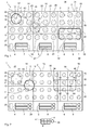
- FIG. 1 is a highly schematic view of a cooking field device 1 according to the invention shown in a plan view.
- the cooking field device 1 comprises a hob 2 and provided thereon cooktop zones 24 to 29 at surface portions 14 to 19 and associated display units 4 to 9, which serve to display the respective operating state of the individual cooktop zones 24 to 29.
- a detection device 20 is shown schematically by dashed lines, which is indirectly or directly connected to the individual induction coils 3.
- a pot 10 is positioned at a pot position 11.
- the geometric center of the pot 12 is indicated by the cross.
- a representative detection point 13 can be calculated, which here in the exemplary embodiment coincides with the center of the pot 12.
- the proportion of the covered area of the respective induction coils 40, 41, 42 and 43 can also be taken into account.
- the detection device 20 determines in which surface section 14 to 19 the pot 10 has been placed.
- the pot 10 was arranged in the surface portion 14, which forms the first cooktop zone 24.
- the cooktop zone 24 are here associated with six induction coils.
- the display unit 4 Since the detection device 20 has detected the pot 10 and its detection point 13 within the first cooking surface zone 24, the display unit 4 is activated and outputs a signal 37, which is indicated here by a hatching.
- the signal 37 can be a continuous lighting of the display unit 4, which is embodied, for example, as an LED.
- the cooktop zone 27 arranged here below the cooktop zone 24 is initially free, so that no pot is detected there and the associated display unit 7 does not emit a signal or does not illuminate.
- this pot 30 On the cooking surface portion 19 here another pot 30 is positioned, which has no round cross section as the pot 10, but has a substantially rectangular and elongated cross-section.
- this pot 30 covers all six induction coils of the associated cooktop zone 29.
- the center of the pot 32 also corresponds again to the representative detection point 33.
- the bottom geometry 36 can be determined from the type and number and position of the covered induction coils 3.
- the detection device 20 performs a new detection. It is determined that the induction coils 51, 52 and 53 are at least partially covered by the pot 10. In this example, the induction coil 50 is not covered.
- the detection device 20 can determine from the type, the number and the known positions of the covered induction coils 51, 52 and 53, a new representative detection point 23, which differs slightly from the new pot center point 22 here. Taking into account the covered surface portions of the induction coils 51, 52 and 53 and taking into account further pot parameters from a previously performed detection of the representative Detection point 23 and its position accuracy can be further improved so that the pot center 22 can be accurately determined.
- the detection device 20 has thus determined that the pot 10 has left the surface section 14, since the new representative detection point 23 is now arranged within the surface section 18. Accordingly, the display unit 8 of the associated cooktop zone 28 is activated. Regardless, however, the induction coils 51, 52 and 53 are activated to deliver the previously set power level with a defined power to the pot 10. To a corresponding extent, the power of the individual induction coils 51, 52 and 53 is adjusted.
- the display unit outputs a corresponding signal 37, which indicates that the cooktop zone 28 is now active. If the output power is insufficient, the signal 37 may optically change and flash, for example, or change color or the like, to alert the user and perhaps reposition the pot, for example, to cover the cover Induction coils gets better.
- FIG. 2 shows another embodiment in which the surface portions 14 to 19 again define cooking surface zones 24 to 29.
- the surface portions 14 to 19 again define cooking surface zones 24 to 29.
- the pot 10 is first positioned in a lower right corner of the surface portion 14, depending on the cost and quality of determining a representative detection point 13 small differences between the position of the representative detection point 13 and the Topfstoffticians 12 may occur, but in the Usually irrelevant.
- the new pot center 22 is still in the first surface section 14 and thus in the cooking surface zone 24.
- the new pot center 22 again coincides exactly with the new detection point 23.
- the induction coils 40, 41, 42 and 43 are covered and now activated while the active at the pot position 11 induction coils are deactivated.
- the display unit 4 remains active even after moving the pot 10 to the position 21.
- a pot 30, for example designed as a roaster which here covers the induction coils 44, 45, 46, 47, 48 and 49. From the number, the position and the degree of coverage of the individual covered induction coils 44 to 49, the pot center 32 and the detection point 33 are determined. In this case, pot parameters 34, such as a length of the pot as dimension 35, can be taken into account. Such information is used in the evaluation by the detection device, for example, if several pots are arranged on the cooking field device 1 and are moved simultaneously or almost simultaneously.
- the embodiments show a hob 2 with six display units 4 to 9, which are arranged here in two rows and three columns. Accordingly, six cooking surface zones 24 to 29 are provided, to which the display units 4 to 9 are assigned accordingly logically.
- the pot position 11 of a pot 10 and its pot geometry is measured. This is preferably done via the degree of coverage of the pot 10 to the induction coil 3. From this, the pot center 12 is calculated via a representative detection point 13. The position of the representative recognition point 13 determines which display unit is activated.
- the ratio of the induction coils to cooktop zones is preferably greater than 2: 1.
- the ratio of the number of induction coils to the number of input positions is preferably greater than 2: 1.
- the ratio of induction coils to input positions can also be 3: 1 or more. Based on the depth of the cooktops, a ratio of the number of cooktop zones to the number of induction coils of greater than 1: 1 may suffice.
- the cooking zone size it is advantageous, but not necessary, for the cooking zone size to be an integer multiple of the induction coil size.
- the size of a cooktop zone preferably corresponds to the total cooktop area divided by the number of display units.
- the power setting for the pot 10 is stored in the hob 2.
- the hob 2 is now the same power to the pot 10 as before lifting off. It is preferably irrelevant whether the new pot position 21 was a significant change in position or not.
- the period between lifting a pot and setting it up can be up to 60 seconds or more. Also possible are periods of up to 600 seconds.
- the method and the hob also allow the operation of two or more pots at the same time. If two pots 10 and 30 are simultaneously positioned on the hob 2, accordingly, for example, two display units 4 and 6 are active. The user in turn assigns each pot 10, 30 the desired performance. The moving and lifting and re-setting of the pots 10, 30 also works simultaneously and independently.
Landscapes
- Physics & Mathematics (AREA)
- Electromagnetism (AREA)
- Induction Heating Cooking Devices (AREA)
Applications Claiming Priority (1)
| Application Number | Priority Date | Filing Date | Title |
|---|---|---|---|
| DE102014105161.0A DE102014105161B4 (de) | 2014-04-11 | 2014-04-11 | Verfahren zum Betreiben einer Kochfeldeinrichtung und Kochfeldeinrichtung |
Publications (1)
| Publication Number | Publication Date |
|---|---|
| EP2931005A1 true EP2931005A1 (fr) | 2015-10-14 |
Family
ID=52692504
Family Applications (1)
| Application Number | Title | Priority Date | Filing Date |
|---|---|---|---|
| EP15159539.4A Withdrawn EP2931005A1 (fr) | 2014-04-11 | 2015-03-18 | Procédé de fonctionnement d'une plaque de cuisson et plaque de cuisson |
Country Status (2)
| Country | Link |
|---|---|
| EP (1) | EP2931005A1 (fr) |
| DE (1) | DE102014105161B4 (fr) |
Cited By (9)
| Publication number | Priority date | Publication date | Assignee | Title |
|---|---|---|---|---|
| EP3330617A1 (fr) * | 2016-11-30 | 2018-06-06 | E.G.O. ELEKTRO-GERÄTEBAU GmbH | Plaque de cuisson et procédé de fonctionnement d'une telle plaque de cuisson |
| EP3401605A1 (fr) * | 2017-05-12 | 2018-11-14 | Electrolux Appliances Aktiebolag | Table de cuisson comportant une interface utilisateur |
| WO2019135115A1 (fr) * | 2018-01-08 | 2019-07-11 | BSH Hausgeräte GmbH | Dispositif table de cuisson |
| CN112393283A (zh) * | 2019-08-12 | 2021-02-23 | 佛山市顺德区美的电热电器制造有限公司 | 烹饪器具 |
| US11039508B2 (en) | 2017-05-19 | 2021-06-15 | Spring (U.S.A.) Corporation | Induction range |
| EP4067749A4 (fr) * | 2019-11-28 | 2023-11-29 | LG Electronics Inc. | Cuiseur électrique assurant des fonctions spécifiques en fonction de gestes de l'utilisateur |
| EP4297531A1 (fr) * | 2022-06-20 | 2023-12-27 | Electrolux Appliances Aktiebolag | Appareil de cuisson et procédé de fonctionnement d'un appareil de cuisson |
| EP4067748A4 (fr) * | 2019-11-25 | 2024-02-28 | Lg Electronics Inc. | Cuiseur électrique fournissant des fonctions spécifiques sans intervention de l'utilisateur |
| US12185447B2 (en) | 2019-05-23 | 2024-12-31 | Spring (U.S.A.) Corporation | Induction heating surface |
Families Citing this family (12)
| Publication number | Priority date | Publication date | Assignee | Title |
|---|---|---|---|---|
| US10605464B2 (en) | 2012-10-15 | 2020-03-31 | Whirlpool Corporation | Induction cooktop |
| ITTO20120896A1 (it) | 2012-10-15 | 2014-04-16 | Indesit Co Spa | Piano cottura a induzione |
| DE102016223849B3 (de) * | 2016-11-30 | 2018-05-09 | E.G.O. Elektro-Gerätebau GmbH | Kochfeld und Verfahren zum Betrieb eines solchen Kochfeldes |
| EP3432682B1 (fr) | 2017-07-18 | 2026-04-08 | Whirlpool Corporation | Procédé de fonctionnement d'une plaque de cuisson par induction et plaque de cuisson faisant appel à un tel procédé |
| US10993292B2 (en) | 2017-10-23 | 2021-04-27 | Whirlpool Corporation | System and method for tuning an induction circuit |
| US11140751B2 (en) | 2018-04-23 | 2021-10-05 | Whirlpool Corporation | System and method for controlling quasi-resonant induction heating devices |
| US12302478B2 (en) | 2018-04-23 | 2025-05-13 | Whirlpool Corporation | Control circuits and methods for distributed induction heating devices |
| US12588112B2 (en) | 2018-04-23 | 2026-03-24 | Whirlpool Corporation | System and method for controlling induction heating devices with series connected switching devices |
| DE102018213655A1 (de) * | 2018-08-14 | 2020-02-20 | E.G.O. Elektro-Gerätebau GmbH | Verfahren zur Ansteuerung einer Heizeinrichtung eines Kochfelds und Kochfeld |
| DE102020103295A1 (de) | 2020-02-10 | 2021-08-12 | Miele & Cie. Kg | Kochfeldeinheit |
| DE102020210482A1 (de) * | 2020-08-18 | 2022-02-24 | BSH Hausgeräte GmbH | Optisches Ermitteln von Betriebszuständen eines Kochfelds |
| DE102020122338A1 (de) | 2020-08-26 | 2022-03-03 | Miele & Cie. Kg | Verfahren und Vorrichtung zum Steuern eines Garprozesses eines Flächeninduktionskochfeldes |
Citations (6)
| Publication number | Priority date | Publication date | Assignee | Title |
|---|---|---|---|---|
| EP1505854A1 (fr) * | 2003-08-04 | 2005-02-09 | Whirpool Corporation | Plaque de cuisson à positionnement indifferent avec interface utilisateur |
| FR2863039A1 (fr) * | 2003-11-27 | 2005-06-03 | Brandt Ind | Procede de chauffage d'un recipient pose sur une table de cuisson a moyens de chauffage associe a des inducteurs |
| EP2065650A2 (fr) * | 2007-11-28 | 2009-06-03 | BSH Bosch und Siemens Hausgeräte GmbH | Appareil ménager doté d'une interface utilisateur comprenant un élément de réglage |
| EP2440011A2 (fr) * | 2010-10-07 | 2012-04-11 | FagorBrandt SAS | Procédé de commande en fonctionnement d'un ensemble d'inducteurs d'une table de cuisson à induction et table de cuisson à induction associée |
| EP2693838A1 (fr) * | 2011-03-29 | 2014-02-05 | Mitsubishi Electric Corporation | Cuisinière à induction |
| EP2709424A1 (fr) * | 2012-09-17 | 2014-03-19 | Electrolux Professional S.p.A. | Plaque de cuisson à induction améliorée |
Family Cites Families (5)
| Publication number | Priority date | Publication date | Assignee | Title |
|---|---|---|---|---|
| DE19681375D2 (de) | 1996-03-29 | 1998-07-23 | Kolja Kuse | Homogenheizfeld |
| ES2331037B1 (es) | 2007-10-25 | 2010-09-21 | Bsh Electrodomesticos España, S.A. | Campo de coccion y procedimiento para el accionamiento de un campo de coccion. |
| ITTO20090942A1 (it) | 2009-12-01 | 2011-06-02 | Indesit Co Spa | Piano cottura e metodo per il suo controllo |
| EP2688364B1 (fr) | 2012-07-20 | 2016-06-22 | BSH Hausgeräte GmbH | Dispositif de champ de cuisson |
| DE102013206758A1 (de) | 2013-04-16 | 2014-10-16 | BSH Bosch und Siemens Hausgeräte GmbH | Kochfeld mit einer Kochzone und einer verkleinerten Symboldarstellung in der Kochzone in einer Anzeigeeinheit sowie Verfahren zum Betreiben eines Kochfelds |
-
2014
- 2014-04-11 DE DE102014105161.0A patent/DE102014105161B4/de active Active
-
2015
- 2015-03-18 EP EP15159539.4A patent/EP2931005A1/fr not_active Withdrawn
Patent Citations (6)
| Publication number | Priority date | Publication date | Assignee | Title |
|---|---|---|---|---|
| EP1505854A1 (fr) * | 2003-08-04 | 2005-02-09 | Whirpool Corporation | Plaque de cuisson à positionnement indifferent avec interface utilisateur |
| FR2863039A1 (fr) * | 2003-11-27 | 2005-06-03 | Brandt Ind | Procede de chauffage d'un recipient pose sur une table de cuisson a moyens de chauffage associe a des inducteurs |
| EP2065650A2 (fr) * | 2007-11-28 | 2009-06-03 | BSH Bosch und Siemens Hausgeräte GmbH | Appareil ménager doté d'une interface utilisateur comprenant un élément de réglage |
| EP2440011A2 (fr) * | 2010-10-07 | 2012-04-11 | FagorBrandt SAS | Procédé de commande en fonctionnement d'un ensemble d'inducteurs d'une table de cuisson à induction et table de cuisson à induction associée |
| EP2693838A1 (fr) * | 2011-03-29 | 2014-02-05 | Mitsubishi Electric Corporation | Cuisinière à induction |
| EP2709424A1 (fr) * | 2012-09-17 | 2014-03-19 | Electrolux Professional S.p.A. | Plaque de cuisson à induction améliorée |
Cited By (13)
| Publication number | Priority date | Publication date | Assignee | Title |
|---|---|---|---|---|
| EP3330617A1 (fr) * | 2016-11-30 | 2018-06-06 | E.G.O. ELEKTRO-GERÄTEBAU GmbH | Plaque de cuisson et procédé de fonctionnement d'une telle plaque de cuisson |
| US11774107B2 (en) | 2017-05-12 | 2023-10-03 | Electrolux Appliances Aktiebolag | Cooking hob with user interface |
| EP3401605A1 (fr) * | 2017-05-12 | 2018-11-14 | Electrolux Appliances Aktiebolag | Table de cuisson comportant une interface utilisateur |
| WO2018206327A1 (fr) * | 2017-05-12 | 2018-11-15 | Electrolux Appliances Aktiebolag | Plaque de cuisson avec interface utilisateur |
| CN110651155A (zh) * | 2017-05-12 | 2020-01-03 | 伊莱克斯家用电器股份公司 | 具有用户界面的烹饪灶具 |
| AU2018264889B2 (en) * | 2017-05-12 | 2024-04-18 | Electrolux Appliances Aktiebolag | Cooking hob with user interface |
| US11039508B2 (en) | 2017-05-19 | 2021-06-15 | Spring (U.S.A.) Corporation | Induction range |
| WO2019135115A1 (fr) * | 2018-01-08 | 2019-07-11 | BSH Hausgeräte GmbH | Dispositif table de cuisson |
| US12185447B2 (en) | 2019-05-23 | 2024-12-31 | Spring (U.S.A.) Corporation | Induction heating surface |
| CN112393283A (zh) * | 2019-08-12 | 2021-02-23 | 佛山市顺德区美的电热电器制造有限公司 | 烹饪器具 |
| EP4067748A4 (fr) * | 2019-11-25 | 2024-02-28 | Lg Electronics Inc. | Cuiseur électrique fournissant des fonctions spécifiques sans intervention de l'utilisateur |
| EP4067749A4 (fr) * | 2019-11-28 | 2023-11-29 | LG Electronics Inc. | Cuiseur électrique assurant des fonctions spécifiques en fonction de gestes de l'utilisateur |
| EP4297531A1 (fr) * | 2022-06-20 | 2023-12-27 | Electrolux Appliances Aktiebolag | Appareil de cuisson et procédé de fonctionnement d'un appareil de cuisson |
Also Published As
| Publication number | Publication date |
|---|---|
| DE102014105161B4 (de) | 2023-03-23 |
| DE102014105161A1 (de) | 2015-10-15 |
Similar Documents
| Publication | Publication Date | Title |
|---|---|---|
| EP2931005A1 (fr) | Procédé de fonctionnement d'une plaque de cuisson et plaque de cuisson | |
| EP2420105B1 (fr) | Plaque de cuisson équipée d'un ensemble de détection et procédé de fonctionnement d'une plaque de cuisson | |
| EP2988573B1 (fr) | Dispositif de plaque de cuisson et procede de fonctionnement | |
| EP2688366B1 (fr) | Dispositif de champ de cuisson | |
| WO2008101766A1 (fr) | Plan de cuisson avec un élément chauffant pouvant être déplacé | |
| CH700524A1 (de) | Haushaltgerät mit berührungsloser Gestenbedienung. | |
| EP3028535B1 (fr) | Système de table de cuisson | |
| WO2014170161A1 (fr) | Table de cuisson comprenant une zone de cuisson et un symbole réduit dans la zone de cuisson dans une unité d'affichage, ainsi que procédé servant à faire fonctionner une table de cuisson | |
| EP2688364A1 (fr) | Dispositif de champ de cuisson | |
| DE102009020905A1 (de) | Kochfeld | |
| EP2688365B1 (fr) | Dispositif de plaque de cuisson | |
| EP3013120B2 (fr) | Plaque de cuisson | |
| DE102014110026B4 (de) | Verfahren zum Betreiben einer Kochfeldeinrichtung und Kochfeldeinrichtung | |
| DE102011051060B4 (de) | Verfahren zum Betrieb eines Gargeräts | |
| EP2751490B1 (fr) | Appareil ménager à élément de commande et procédé de fonctionnement d'un appareil ménager | |
| EP3021639B1 (fr) | Procédé de fonctionnement d'une plaque de cuisson et plaque de cuisson | |
| EP3702747B1 (fr) | Dispositif formant plaque de cuisson | |
| EP2872830B1 (fr) | Procédé d'affichage de paramètres d'un processus de cuisson et dispositif d'affichage d'un appareil de cuisson | |
| EP3537049A1 (fr) | Procédé de représentation d'un affichage sur un champ de cuisson et champ de cuisson | |
| EP3330617B1 (fr) | Plaque de cuisson et procédé de fonctionnement d'une telle plaque de cuisson | |
| EP2642821A1 (fr) | Procédé de fonctionnement d'un champ de cuisson à induction et champ de cuisson à induction | |
| DE102015118453A1 (de) | Verfahren zum Betreiben einer Kochfeldeinrichtung | |
| EP0806887A1 (fr) | Procédé et dispositif pour reconnaître le stade de cuisson d'aliments à cuire | |
| EP3077733B1 (fr) | Procédé d'affichage d'informations de traitement d'un procédé de cuisson | |
| EP2258986A2 (fr) | Plaque de cuisson |
Legal Events
| Date | Code | Title | Description |
|---|---|---|---|
| PUAI | Public reference made under article 153(3) epc to a published international application that has entered the european phase |
Free format text: ORIGINAL CODE: 0009012 |
|
| AK | Designated contracting states |
Kind code of ref document: A1 Designated state(s): AL AT BE BG CH CY CZ DE DK EE ES FI FR GB GR HR HU IE IS IT LI LT LU LV MC MK MT NL NO PL PT RO RS SE SI SK SM TR |
|
| AX | Request for extension of the european patent |
Extension state: BA ME |
|
| STAA | Information on the status of an ep patent application or granted ep patent |
Free format text: STATUS: THE APPLICATION IS DEEMED TO BE WITHDRAWN |
|
| 18D | Application deemed to be withdrawn |
Effective date: 20160415 |