EP2931005A1 - Method for operating a cooking field device and cooking field device - Google Patents
Method for operating a cooking field device and cooking field device Download PDFInfo
- Publication number
- EP2931005A1 EP2931005A1 EP15159539.4A EP15159539A EP2931005A1 EP 2931005 A1 EP2931005 A1 EP 2931005A1 EP 15159539 A EP15159539 A EP 15159539A EP 2931005 A1 EP2931005 A1 EP 2931005A1
- Authority
- EP
- European Patent Office
- Prior art keywords
- pot
- induction coils
- hob
- display unit
- zone
- Prior art date
- Legal status (The legal status is an assumption and is not a legal conclusion. Google has not performed a legal analysis and makes no representation as to the accuracy of the status listed.)
- Withdrawn
Links
- 238000010411 cooking Methods 0.000 title claims abstract description 64
- 238000000034 method Methods 0.000 title claims abstract description 37
- 230000006698 induction Effects 0.000 claims abstract description 94
- 238000001514 detection method Methods 0.000 claims abstract description 54
- 238000005580 one pot reaction Methods 0.000 claims description 3
- 238000006073 displacement reaction Methods 0.000 claims description 2
- 230000004913 activation Effects 0.000 description 2
- 238000011161 development Methods 0.000 description 2
- 230000018109 developmental process Effects 0.000 description 2
- 238000010438 heat treatment Methods 0.000 description 2
- 230000001419 dependent effect Effects 0.000 description 1
- 238000011156 evaluation Methods 0.000 description 1
- 230000012447 hatching Effects 0.000 description 1
- 238000013507 mapping Methods 0.000 description 1
- 238000005259 measurement Methods 0.000 description 1
- 230000033764 rhythmic process Effects 0.000 description 1
- 230000005236 sound signal Effects 0.000 description 1
Images
Classifications
-
- H—ELECTRICITY
- H05—ELECTRIC TECHNIQUES NOT OTHERWISE PROVIDED FOR
- H05B—ELECTRIC HEATING; ELECTRIC LIGHT SOURCES NOT OTHERWISE PROVIDED FOR; CIRCUIT ARRANGEMENTS FOR ELECTRIC LIGHT SOURCES, IN GENERAL
- H05B6/00—Heating by electric, magnetic or electromagnetic fields
- H05B6/02—Induction heating
- H05B6/06—Control, e.g. of temperature, of power
- H05B6/062—Control, e.g. of temperature, of power for cooking plates or the like
-
- H—ELECTRICITY
- H05—ELECTRIC TECHNIQUES NOT OTHERWISE PROVIDED FOR
- H05B—ELECTRIC HEATING; ELECTRIC LIGHT SOURCES NOT OTHERWISE PROVIDED FOR; CIRCUIT ARRANGEMENTS FOR ELECTRIC LIGHT SOURCES, IN GENERAL
- H05B2213/00—Aspects relating both to resistive heating and to induction heating, covered by H05B3/00 and H05B6/00
- H05B2213/03—Heating plates made out of a matrix of heating elements that can define heating areas adapted to cookware randomly placed on the heating plate
-
- H—ELECTRICITY
- H05—ELECTRIC TECHNIQUES NOT OTHERWISE PROVIDED FOR
- H05B—ELECTRIC HEATING; ELECTRIC LIGHT SOURCES NOT OTHERWISE PROVIDED FOR; CIRCUIT ARRANGEMENTS FOR ELECTRIC LIGHT SOURCES, IN GENERAL
- H05B2213/00—Aspects relating both to resistive heating and to induction heating, covered by H05B3/00 and H05B6/00
- H05B2213/05—Heating plates with pan detection means
Definitions
- the present invention relates to a method for operating a cooking field device and a cooking field device with which such a method can be carried out.
- the invention relates to a cooking field device with an induction hob, wherein a plurality of induction coils generates the required heating energy and emits by induction to the bottom of the pot positioned on the hob.
- graphical displays can be used which have a plurality of display points on a display surface and thus a positioned on the hob pot, for. Mapping true to scale so that the user can directly see which pot is located where.
- the inventive method for operating a cooking field device is performed with a hob having a plurality of induction coils and a smaller and predetermined number of display units. Each display unit is associated with a predetermined surface portion of the hob. Each display unit serves to indicate an operating state of an associated cooktop zone.
- a detection device a pot position is detected on the hob, and there are identified by the pot at the current pot position covered induction coils. From the positions of the currently identified induction coils, a representative detection point for the current pot position is determined. On the basis of the position of the representative detection point, the associated predetermined surface section of the hob is determined, and the current display unit associated with the predetermined surface section is determined.
- a significant advantage of the method according to the invention is that a discrete and predetermined and usually quite small number of display units is used to represent the operating conditions of a discrete number of cooking surface zones, each cooking surface zone may have a plurality of induction coils.
- a cooktop zone is preferably substantially or at least partially associated with the surface section.
- the coordinates of the Center of the detected induction coils can be used.
- a weighting with the area of the covered induction coils is used to make a geometric weighting.
- a covered induction coil is in the context of the present invention, an induction coil, which is covered to a considerable extent by a pot. This means that when operating a covered induction coil, this induction coil induces energy in the pot bottom to a considerable extent. Alternatively, it is possible to approximate a geometric overlap. Thus, a coil is considered covered if it appreciably or even covers the bottom of the pot in the vertical direction.
- the cooktop in the context of the present invention is a ceremoniesnkochfeld, in which the surface portions and the cooktop zones are arranged in particular in rows and columns.
- the number of induction coils is preferably considerably larger than the number of input units for operating the cooking field device. It is possible and preferred that the number of input units corresponds to the number of cooktop zones. But it is also possible that a small number and z. B. also serves only a single input unit to operate all cooktop zones.
- At least one pot parameter is determined from the number and positions of the currently identified induction coils.
- a geometric image of a pot positioned on the hob can be determined. If the induction coils are relatively small in relation to the dimensions of the pot bottom and a corresponding number of induction coils are used and arranged relatively dense, a relatively accurate geometric shape of the pot bottom geometry and a correspondingly accurate pot dimension can be determined.
- the degree of overlap of the individual induction coils can also be taken into account in order to determine a pot bottom geometry and / or a pot dimension.
- a measure of a degree of coverage may be determined by taking into account the power output of an induction coil compared to its power setting.
- An induction coil completely covered by the bottom of the pot emits more power at a given setting than an induction coil, which is covered, for example, only half or a quarter of a pot bottom.
- the ratio of the active power to the apparent power of a coil for determining the coverage.
- the phase relationship between coil current and coil voltage is a measure of the overlap and can be evaluated.
- Such cover values can in turn be used to determine the pot size and pot geometry or pot parameters.
- At least one pot parameter is taken into account for determining the currently representative detection point. If, for example, based on the number, position and degree of coverage of the identified induction coils, it is concluded that the bottom of the pot is circular, then this information can be used to determine a meaningful representative detection point. If, on the other hand, it is determined that the pot bottom geometry is more rectangular or elongated rectangular, then this information can also be used to determine a meaningful representative detection point.
- a new representative detection point is determined. It is also possible for a new representative detection point to be determined at fixed or variable time intervals. Thus, it can be ensured that changes in the operation are recognized in good time, at least if the time interval between two successive determinations is sufficiently small to detect dynamic processes. Time intervals between measurements in the second or millisecond range are possible.
- the associated display unit when the representative recognition point changes, is redetermined and activated when the associated display unit has changed. For example, it is possible that a pot is first detected on a particular cooktop zone. If the user deliberately or unconsciously shifts the pot positioned, for example, at the edge of the cooking surface zone during the cooking process, the pot can be moved from the first cooking surface zone, for example, into the second cooking surface zone.
- the display unit of the first cooktop zone is deactivated and the display unit of the second cooktop zone is activated. In a corresponding manner, in each case the previous display unit is deactivated and the newly assigned display unit is activated.
- the pot position is updated and it will maintain the set power level, even if the surface section is changed.
- the set power level and other set parameters are maintained, although the associated cooktop zone has changed.
- the respectively covered induction coils of the now second cooktop zone are activated, while the no longer covered induction coils in the first cooking surface zone are disabled.
- the display unit of the second cooktop zone is activated. In any case, it is possible that a pot is heated with indication coils from different surface sections.
- Such a configuration is very advantageous because it greatly facilitates the cooking process for the user and makes a large number of settings superfluous. In many cooking processes, it can happen unintentionally or intentionally that a pot leaves a cooking surface zone. With this embodiment of the method according to the invention a manual activation of the induction coils in the second cooktop zone is not necessary, but the power level once set follows the pot, even if the pot leaves the first activated cooktop zone.
- the current covered by the pot induction coils are operated according to the set power level. It is possible and preferred that after each change in position of the pot, the respective power output of each currently covered by the pot induction coils is adjusted. This is possible if the pot is moved within a cooktop zone. This is also possible if the pot is moved or displaced from one cooktop zone to another cooktop zone.
- the power output of each currently covered by the pot induction coils is set so that the sum of the power outputs of the covered induction coils at least substantially equal to the set power level. Possible deviations are, as they are common in the prior art.
- a signal is output when the power output of each currently covered by the pot induction coils falls below or exceeds the set power level by a predetermined value.
- the respective power of the individual induction coils is preferably reduced accordingly.
- a signal is preferably output from the associated display unit.
- the display unit may be lit by a flash signal having a predetermined clock frequency or a certain rhythm, or may also output a sound signal or another signal in order to alert the user to the current situation.
- the current display unit is checked after each change in position of the pot and adjusted if necessary.
- the set power level is stored for a predetermined period after lifting or after removing the pot.
- the previously set power level again set or remains set, in particular at least when the restart is detected within the predetermined period.
- a predetermined period may be, for example, 60 seconds or even 2 minutes, 5 minutes or 10 minutes or the like.
- the power level also be maintained when the pot is placed on another surface portion.
- information for pot detection can be stored.
- Such information may in particular be the temperature of the pot, a phase position of the inductor current, an inductor current, a pot size and a Topfart.
- Other parameters of the pot can also be used.
- the pot can be reliably detected, for example, reliably over the temperature of the pot, the bottom of the pot and the pot dimensions, so that even after removing a pot and restarting the pot is reliably recognized again to allow further operation, in which no User input must be made.
- the currently assigned display unit outputs a signal when the currently assigned display unit is set. This is done for example after the first recognition of a pot in a cooking process. If the currently assigned display unit is specified, preferably a power level for the currently assigned cooktop zone can be selected. Such an operating mode is particularly advantageous if a common input unit is provided for a plurality of cooktop zones.
- a signal may be, for example, a flashing light, flashing or change of color to alert the user.
- the method is carried out simultaneously when using multiple pots and also when using multiple pots.
- the individual pots can then be reliably distinguished from each other.
- a cooking field device has a hob, which is associated with a plurality of induction coils and a smaller and predetermined number of display units. Each display unit is associated with a predetermined area portion of the hob and each display unit serves to indicate an operating state of an associated cooking area zone.
- a detection device is provided which is suitable and arranged to detect a pot position on the hob and to identify the induction coils covered by the pot at the current pot position and to determine a representative detection point for the current pot position from the positions of the currently identified induction coils , In this case, the detection device is furthermore suitable and set up to determine the associated surface section of the hob based on the position of the representative detection point and to determine the current display unit assigned to the surface section.
- the cooking field device has a plurality of induction coils per cooking surface zone.
- the number of induction coils per cooktop zone is preferably less than or equal to 2. It is possible and preferred that each induction coil is assigned to exactly one cooktop zone. But it is also possible that individual induction coils are each associated with two cooktop zones when the boundaries of the surface sections intersect the surfaces of the induction coils. Even a flexible assignment during operation is possible.
- the invention allows the operation of a hob, in which the power output is associated with the pot and no longer with a cooking or cooking surface zone.
- a cooking field device is used which has more induction coils than display positions or display units.
- On the display units are each a display element and optionally an input unit for adjusting the power for each cooking surface zone. Or there is provided an input unit for adjusting the power of all cooktop zones.
- the user puts a pot on the hob of the hob field.
- the hob can have no mark for positioning the pot.
- the detection device of the cooking field device detects the position of the pot and calculates the associated display unit from the number and the positions of the covered coil devices.
- the associated display unit lights up and thereby signals the input readiness to the user.
- the user can then select the power level.
- the corresponding power is delivered to the pot. If the user now shifts the pot to any other position (not only within the cooking surface zone) on the hob as a whole, then recognizing the cooking field device detects the displacement and recalculates the position of the pot.
- the display unit of the other cooking surface zone is activated while the display unit of the previously active cooking surface zone is deactivated.
- the power level is set automatically at the new position on the new cooktop zone. It is advantageous that the user does not have to make any further inputs, but that this process takes place automatically when moving a pot.
- the display setting will not change and the same display unit will remain active.
- the power delivered to the pot is recalculated and it may be that other induction coils are activated or operated at a different level.
- the cooking field device can not balance the power, it may provide a suitable signal, e.g. emit a flashing on the display unit or a buzzer or the like sounds to alert the user that the set power level is not reached.
- the pot bottom geometry such as the length, width and diameter of the pot, can be used.
- the number of induction coils and the area dimensions of the active induction coil and the number of display units and the position of the display units and the active Koch vomiretician can be used.
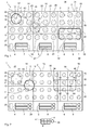
- FIG. 1 is a highly schematic view of a cooking field device 1 according to the invention shown in a plan view.
- the cooking field device 1 comprises a hob 2 and provided thereon cooktop zones 24 to 29 at surface portions 14 to 19 and associated display units 4 to 9, which serve to display the respective operating state of the individual cooktop zones 24 to 29.
- a detection device 20 is shown schematically by dashed lines, which is indirectly or directly connected to the individual induction coils 3.
- a pot 10 is positioned at a pot position 11.
- the geometric center of the pot 12 is indicated by the cross.
- a representative detection point 13 can be calculated, which here in the exemplary embodiment coincides with the center of the pot 12.
- the proportion of the covered area of the respective induction coils 40, 41, 42 and 43 can also be taken into account.
- the detection device 20 determines in which surface section 14 to 19 the pot 10 has been placed.
- the pot 10 was arranged in the surface portion 14, which forms the first cooktop zone 24.
- the cooktop zone 24 are here associated with six induction coils.
- the display unit 4 Since the detection device 20 has detected the pot 10 and its detection point 13 within the first cooking surface zone 24, the display unit 4 is activated and outputs a signal 37, which is indicated here by a hatching.
- the signal 37 can be a continuous lighting of the display unit 4, which is embodied, for example, as an LED.
- the cooktop zone 27 arranged here below the cooktop zone 24 is initially free, so that no pot is detected there and the associated display unit 7 does not emit a signal or does not illuminate.
- this pot 30 On the cooking surface portion 19 here another pot 30 is positioned, which has no round cross section as the pot 10, but has a substantially rectangular and elongated cross-section.
- this pot 30 covers all six induction coils of the associated cooktop zone 29.
- the center of the pot 32 also corresponds again to the representative detection point 33.
- the bottom geometry 36 can be determined from the type and number and position of the covered induction coils 3.
- the detection device 20 performs a new detection. It is determined that the induction coils 51, 52 and 53 are at least partially covered by the pot 10. In this example, the induction coil 50 is not covered.
- the detection device 20 can determine from the type, the number and the known positions of the covered induction coils 51, 52 and 53, a new representative detection point 23, which differs slightly from the new pot center point 22 here. Taking into account the covered surface portions of the induction coils 51, 52 and 53 and taking into account further pot parameters from a previously performed detection of the representative Detection point 23 and its position accuracy can be further improved so that the pot center 22 can be accurately determined.
- the detection device 20 has thus determined that the pot 10 has left the surface section 14, since the new representative detection point 23 is now arranged within the surface section 18. Accordingly, the display unit 8 of the associated cooktop zone 28 is activated. Regardless, however, the induction coils 51, 52 and 53 are activated to deliver the previously set power level with a defined power to the pot 10. To a corresponding extent, the power of the individual induction coils 51, 52 and 53 is adjusted.
- the display unit outputs a corresponding signal 37, which indicates that the cooktop zone 28 is now active. If the output power is insufficient, the signal 37 may optically change and flash, for example, or change color or the like, to alert the user and perhaps reposition the pot, for example, to cover the cover Induction coils gets better.
- FIG. 2 shows another embodiment in which the surface portions 14 to 19 again define cooking surface zones 24 to 29.
- the surface portions 14 to 19 again define cooking surface zones 24 to 29.
- the pot 10 is first positioned in a lower right corner of the surface portion 14, depending on the cost and quality of determining a representative detection point 13 small differences between the position of the representative detection point 13 and the Topfstoffticians 12 may occur, but in the Usually irrelevant.
- the new pot center 22 is still in the first surface section 14 and thus in the cooking surface zone 24.
- the new pot center 22 again coincides exactly with the new detection point 23.
- the induction coils 40, 41, 42 and 43 are covered and now activated while the active at the pot position 11 induction coils are deactivated.
- the display unit 4 remains active even after moving the pot 10 to the position 21.
- a pot 30, for example designed as a roaster which here covers the induction coils 44, 45, 46, 47, 48 and 49. From the number, the position and the degree of coverage of the individual covered induction coils 44 to 49, the pot center 32 and the detection point 33 are determined. In this case, pot parameters 34, such as a length of the pot as dimension 35, can be taken into account. Such information is used in the evaluation by the detection device, for example, if several pots are arranged on the cooking field device 1 and are moved simultaneously or almost simultaneously.
- the embodiments show a hob 2 with six display units 4 to 9, which are arranged here in two rows and three columns. Accordingly, six cooking surface zones 24 to 29 are provided, to which the display units 4 to 9 are assigned accordingly logically.
- the pot position 11 of a pot 10 and its pot geometry is measured. This is preferably done via the degree of coverage of the pot 10 to the induction coil 3. From this, the pot center 12 is calculated via a representative detection point 13. The position of the representative recognition point 13 determines which display unit is activated.
- the ratio of the induction coils to cooktop zones is preferably greater than 2: 1.
- the ratio of the number of induction coils to the number of input positions is preferably greater than 2: 1.
- the ratio of induction coils to input positions can also be 3: 1 or more. Based on the depth of the cooktops, a ratio of the number of cooktop zones to the number of induction coils of greater than 1: 1 may suffice.
- the cooking zone size it is advantageous, but not necessary, for the cooking zone size to be an integer multiple of the induction coil size.
- the size of a cooktop zone preferably corresponds to the total cooktop area divided by the number of display units.
- the power setting for the pot 10 is stored in the hob 2.
- the hob 2 is now the same power to the pot 10 as before lifting off. It is preferably irrelevant whether the new pot position 21 was a significant change in position or not.
- the period between lifting a pot and setting it up can be up to 60 seconds or more. Also possible are periods of up to 600 seconds.
- the method and the hob also allow the operation of two or more pots at the same time. If two pots 10 and 30 are simultaneously positioned on the hob 2, accordingly, for example, two display units 4 and 6 are active. The user in turn assigns each pot 10, 30 the desired performance. The moving and lifting and re-setting of the pots 10, 30 also works simultaneously and independently.
Landscapes
- Physics & Mathematics (AREA)
- Electromagnetism (AREA)
- Induction Heating Cooking Devices (AREA)
Abstract
Verfahren zum Betreiben einer Kochfeldeinrichtung (1) und Kochfeldeinrichtung (1), wobei die Kochfeldeinrichtung (1) ein Kochfeld (2) aufweist, dem eine Vielzahl von Induktionsspulen (3) und eine geringere und vorbestimmte Anzahl an Anzeigeeinheiten (4 - 9) zugeordnet sind. Jede Anzeigeeinheit (4 - 9) ist einem vorbestimmten Flächenabschnitt (14 - 19) des Kochfeldes (2) zugeordnet und dient zur Anzeige eines Betriebszustandes einer zugeordneten Kochflächenzone (24 - 29). Mit einer Erkennungseinrichtung (20) wird eine Topfposition (11) auf dem Kochfeld (2) erkannt und es werden die von dem Topf (10) an der aktuellen Topfposition (11) überdeckten Induktionsspulen (40 - 43) identifiziert. Aus den Positionen der aktuell identifizierten Induktionsspulen (40 - 43) wird ein repräsentativer Erkennungspunkt (13) für die aktuelle Topfposition (11) ermittelt. Anhand der Lage des repräsentativen Erkennungspunkts (13) wird der zugehörige vorbestimmte Flächenabschnitt (14 - 19) des Kochfeldes (2) ermittelt und es wird die dem vorbestimmten Flächenabschnitt (14 - 19) zugeordnete aktuelle Anzeigeeinheit (4 - 9) festgelegt."Method for operating a cooking field device (1) and cooking field device (1), wherein the cooking field device (1) has a hob (2) to which a plurality of induction coils (3) and a smaller and predetermined number of display units (4-9) are assigned , Each display unit (4-9) is associated with a predetermined area portion (14-19) of the hob (2) and serves to indicate an operating condition of an associated cooktop zone (24-29). With a detection device (20), a pot position (11) on the hob (2) is detected and there are identified by the pot (10) at the current pot position (11) covered induction coils (40 - 43). From the positions of the currently identified induction coils (40-43) a representative detection point (13) for the current pot position (11) is determined. On the basis of the position of the representative detection point (13), the associated predetermined area section (14-19) of the hob (2) is determined and the current display unit (4-9) associated with the predetermined area section (14-19) is determined. "
Description
Die vorliegende Erfindung betrifft ein Verfahren zum Betreiben einer Kochfeldeinrichtung und eine Kochfeldeinrichtung, mit der ein solches Verfahren durchgeführt werden kann. Insbesondere betrifft die Erfindung eine Kochfeldeinrichtung mit einem Induktionskochfeld, bei dem eine Mehrzahl von Induktionsspulen die benötigte Heizenergie erzeugt und durch Induktion an den Topfboden des auf dem Kochfeld positionierten Topfes abgibt.The present invention relates to a method for operating a cooking field device and a cooking field device with which such a method can be carried out. In particular, the invention relates to a cooking field device with an induction hob, wherein a plurality of induction coils generates the required heating energy and emits by induction to the bottom of the pot positioned on the hob.
Zur flexiblen Verwendung verschiedener großer Töpfe und unterschiedlicher Topfbodengeometrien auf dem Kochfeld ist es vorteilhaft, wenn mehrere kleinere Induktionsspulen einer Kochflächenzone zugeordnet sind, sodass bei der Beheizung eines auf der Kochflächenzone positionierten Topfes jeweils zwei oder mehr vom Topf überdeckte Induktionsspulen aktiv sind. Dadurch kann an einer Kochflächenzone nicht nur eine bestimmte Topfart und Topfgröße eingesetzt werden, sondern die Kochflächenzone eignet sich für unterschiedlichste Töpfe. Eine Anzeige, wie beispielsweise eine Betriebsleuchte, kann zum Anzeigen des Betriebszustandes dienen.For the flexible use of different large pots and different Topfbodengeometrien on the hob, it is advantageous if several smaller induction coils are assigned to a cooktop zone, so that when heating a positioned on the cooktop zone each pot two or more covered by the pot induction coils are active. As a result, not only a certain type of pot and pot size can be used on a cooktop zone, but the cooktop zone is suitable for a variety of pots. A display, such as an operating light, may be used to indicate the operating condition.
Werden bei klassischen Kochfeldern mehrere einzelne Kochzonen vorgesehen, bei denen jeweils genau eine Induktionsspule zur Beheizung eines entsprechend ausgebildeten Topfes dient, so ist eine Zuordnung von diskreten Anzeigeelementen zu den Kochzonen einfach und direkt ersichtlich. Wird aber eine Vielzahl von kleineren Induktionsspulen an mehreren Kochflächenzonen eines Kochfeldes eingesetzt, so kann es für den Benutzer fraglich sein, auf welcher Kochflächenzone der Topf angeordnet ist. Nämlich z. B. dann, wenn der Topf an der Grenze einer Kochflächenzone zu einer anderen Kochflächenzone positioniert wird oder wenn die Fläche des Topfbodens die Grenze teilweise schon überschreitet.If a plurality of individual cooking zones are provided in the case of classic cooktops, in which case exactly one induction coil serves in each case to heat a correspondingly designed pot, an assignment of discrete display elements to the cooking zones can be easily and directly seen. If, however, a multiplicity of smaller induction coils are used at several cooktop zones of a cooktop, then it may be questionable for the user on which cooktop zone the pan is arranged. Namely z. B. when the pot is positioned at the boundary of a cooktop zone to another cooktop zone or when the surface of the bottom of the pot already exceeds the limit in part.
Um eine eindeutige und für den Benutzer direkt ersichtliche Zuordnung eines auf dem Kochfeld positionierten Topfes zu einer Kochflächenzone zu ermöglichen, können deshalb grafische Displays eingesetzt werden, die auf einer Anzeigefläche eine Vielzahl von Anzeigepunkten aufweisen und somit einen auf dem Kochfeld positionierten Topf z.B. maßstabsgetreu abbilden, sodass der Benutzer direkt erkennt, welcher Topf wo angeordnet ist.In order to allow a clear and directly visible to the user assignment of a positioned on the hob pot to a cooking surface zone, therefore, graphical displays can be used which have a plurality of display points on a display surface and thus a positioned on the hob pot, for. Mapping true to scale so that the user can directly see which pot is located where.
Der Einsatz grafischer Displays erhöht die Kosten für derartige Kochfelder nicht unbeträchtlich. Außerdem erwarten Kunden einen langjährigen ungestörten und zuverlässigen Betrieb eines solchen Kochfelds. Um dies sicherzustellen, müssen entsprechend hochwertige Displays verwendet werden, was die Kosten noch weiter steigert.The use of graphic displays increases the costs of such hobs not inconsiderable. In addition, customers expect many years of undisturbed and reliable operation of such a hob. To ensure this, high-quality displays must be used, which increases costs even further.
Es ist deshalb die Aufgabe der vorliegenden Erfindung, ein Verfahren zum Betreiben einer Kochfeldeinrichtung und eine derartige Kochfeldeinrichtung zur Verfügung zu stellen, womit eine kostengünstigere, zuverlässige und übersichtliche Zuordnung von Töpfen auf solchen Kochfeldeinrichtungen ermöglicht wird.It is therefore an object of the present invention to provide a method for operating a cooking field device and such a cooking field device available, whereby a more cost-effective, reliable and clear allocation of pots on such hob facilities is possible.
Diese Aufgabe wird durch ein Verfahren mit den Merkmalen des Anspruchs 1 gelöst. Die erfindungsgemäße Kochfeldeinrichtung ist Gegenstand des Anspruchs 16. Einige Vorteile und Merkmale der vorliegenden Erfindung ergeben sich aus den Unteransprüchen. Weitere Vorteile und Merkmale sind in der allgemeinen Beschreibung und der Beschreibung der Ausführungsbeispiele angegeben.This object is achieved by a method having the features of
Das erfindungsgemäße Verfahren zum Betreiben einer Kochfeldeinrichtung wird mit einem Kochfeld durchgeführt, das eine Vielzahl von Induktionsspulen und eine geringere und vorbestimmte Anzahl an Anzeigeeinheiten aufweist. Jeder Anzeigeeinheit ist ein vorbestimmter Flächenabschnitt des Kochfeldes zugeordnet. Jede Anzeigeeinheit dient zur Anzeige eines Betriebszustandes einer zugeordneten Kochflächenzone. Mit einer Erkennungseinrichtung wird eine Topfposition auf dem Kochfeld erkannt, und es werden die von dem Topf an der aktuellen Topfposition überdeckten Induktionsspulen identifiziert. Aus den Positionen der aktuell identifizierten Induktionsspulen wird ein repräsentativer Erkennungspunkt für die aktuelle Topfposition ermittelt. Anhand der Lage des repräsentativen Erkennungspunkts wird der zugehörige vorbestimmte Flächenabschnitt des Kochfeldes ermittelt, und es wird die dem vorbestimmten Flächenabschnitt zugeordnete aktuelle Anzeigeeinheit festgelegt.The inventive method for operating a cooking field device is performed with a hob having a plurality of induction coils and a smaller and predetermined number of display units. Each display unit is associated with a predetermined surface portion of the hob. Each display unit serves to indicate an operating state of an associated cooktop zone. With a detection device, a pot position is detected on the hob, and there are identified by the pot at the current pot position covered induction coils. From the positions of the currently identified induction coils, a representative detection point for the current pot position is determined. On the basis of the position of the representative detection point, the associated predetermined surface section of the hob is determined, and the current display unit associated with the predetermined surface section is determined.
Das erfindungsgemäße Verfahren hat viele Vorteile. Ein erheblicher Vorteil des erfindungsgemäßen Verfahrens liegt darin, dass eine diskrete und vorbestimmte und meist recht geringe Anzahl an Anzeigeeinheiten eingesetzt wird, um die Betriebszustände einer diskreten Anzahl an Kochflächenzonen darzustellen, wobei jede Kochflächenzone mehrere Induktionsspulen aufweisen kann.The method according to the invention has many advantages. A significant advantage of the method according to the invention is that a discrete and predetermined and usually quite small number of display units is used to represent the operating conditions of a discrete number of cooking surface zones, each cooking surface zone may have a plurality of induction coils.
Dadurch ist es nicht nötig, ein hochauflösendes Display oder eine hochauflösende Anzeige einzusetzen, bei der eine Vielzahl von möglichen Topfpositionen maßstabsgetreu wiedergegeben wird, sondern es reicht aus, eine Anzahl von beispielsweise Leuchtsignalen zur Verfügung zu stellen, die der Anzahl der Kochflächenzonen entspricht. In einem einfachen Fall können beispielsweise Leuchtdioden als Anzeigeeinheiten verwendet werden, wobei die Anzahl der Leuchtdioden der Anzahl der Kochflächenzonen entspricht. Für jede Kochflächenzone können wiederum 2, 3, 4 oder mehr Induktionsspulen vorgesehen sein, um unterschiedlichste Topfformen und Topfgrößen jeweils optimal beheizen zu können.As a result, it is not necessary to use a high-resolution display or a high-resolution display in which a large number of possible pot positions is reproduced true to scale, but it is sufficient to provide a number of, for example, luminous signals corresponding to the number of cooking surface zones. In a simple case, for example, light-emitting diodes can be used as display units, the number of light-emitting diodes corresponding to the number of cooktop zones. In turn, 2, 3, 4 or more induction coils can be provided for each cooktop zone in order to be able to optimally heat different pot shapes and pot sizes.
Bei der Erfindung ist eine Kochflächenzone vorzugsweise im Wesentlichen bzw. wenigstens teilweise dem Flächenabschnitt zugeordnet. Als Erkennungspunkt können die Koordinaten des Mittelpunktes der erkannten Induktionsspulen verwendet werden. Vorzugsweise wird bei der Ermittlung eines Erkennungspunktes eine Gewichtung mit der Fläche der überdeckten Induktionsspulen verwendet, um eine geometrische Gewichtung vorzunehmen.In the invention, a cooktop zone is preferably substantially or at least partially associated with the surface section. As a detection point, the coordinates of the Center of the detected induction coils can be used. Preferably, when determining a detection point, a weighting with the area of the covered induction coils is used to make a geometric weighting.
Eine überdeckte Induktionsspule ist im Sinne der vorliegenden Erfindung eine Induktionsspule, die in einem erheblichen Maße von einem Topf überdeckt wird. Das bedeutet, dass bei Betrieb einer überdeckten Induktionsspule diese Induktionsspule Energie in dem Topfboden in einem erheblichen Maße induziert. Alternativ ist es möglich, eine geometrische Überdeckung näherungsweise heranzuziehen. So wird eine Spule als überdeckt angesehen, wenn sie den Topfboden in vertikaler Richtung nennenswert oder überhaupt überdeckt.A covered induction coil is in the context of the present invention, an induction coil, which is covered to a considerable extent by a pot. This means that when operating a covered induction coil, this induction coil induces energy in the pot bottom to a considerable extent. Alternatively, it is possible to approximate a geometric overlap. Thus, a coil is considered covered if it appreciably or even covers the bottom of the pot in the vertical direction.
Das Kochfeld im Sinne der vorliegenden Erfindung ist ein Flächenkochfeld, bei dem die Flächenabschnitte und die Kochflächenzonen insbesondere in Zeilen und Spalten angeordnet sind. Die Anzahl der Induktionsspulen ist vorzugsweise erheblich größer als die Anzahl der Eingabeeinheiten zur Bedienung der Kochfeldeinrichtung. Es ist möglich und bevorzugt, dass die Anzahl der Eingabeeinheiten der Anzahl der Kochflächenzonen entspricht. Möglich ist es aber auch, dass eine geringe Anzahl und z. B. auch nur eine einzelne Eingabeeinheit zur Bedienung aller Kochflächenzonen dient.The cooktop in the context of the present invention is a Flächenkochfeld, in which the surface portions and the cooktop zones are arranged in particular in rows and columns. The number of induction coils is preferably considerably larger than the number of input units for operating the cooking field device. It is possible and preferred that the number of input units corresponds to the number of cooktop zones. But it is also possible that a small number and z. B. also serves only a single input unit to operate all cooktop zones.
In einer bevorzugten Weiterbildung wird aus der Anzahl und den Positionen der aktuell identifizierten Induktionsspulen wenigstens ein Topfparameter, wie eine Topfbodengeometrie und/oder eine Topfabmessung ermittelt. Über die Anzahl der überdeckten und somit identifizierten Induktionsspulen kann ein geometrisches Abbild eines auf dem Kochfeld positionierten Topfes ermittelt werden. Sind die Induktionsspulen relativ klein in Relation zu den Abmessungen des Topfbodens und wird eine entsprechende Anzahl von Induktionsspulen eingesetzt und relativ dicht angeordnet, so kann eine relativ genaue geometrische Form der Topfbodengeometrie und eine entsprechend genaue Topfabmessung ermittelt werden. Bei dem Einsatz von größeren Induktionsspulen kann auch der Überdeckungsgrad der einzelnen Induktionsspulen berücksichtigt werden, um eine Topfbodengeometrie und/oder eine Topfabmessung zu ermitteln. Ein Maß für einen Überdeckungsgrad kann beispielsweise ermittelt werden, in dem die Leistungsabgabe einer Induktionsspule im Vergleich zu ihrer Leistungseinstellung berücksichtigt wird. Eine vollständig von dem Topfboden überdeckte Induktionsspule gibt bei einer gegebenen Einstellung mehr Leistung ab als eine Induktionsspule, die beispielsweise nur zur Hälfte oder zu einem Viertel von einem Topfboden überdeckt wird. Anhand der abgegebenen Leistungswerte bei einer vorgegebenen Einstellung kann auf die Überdeckung zurückgeschlossen werden. Es kann auch das Verhältnis von der Wirkleistung zur Scheinleistung einer Spule zur Bestimmung der Überdeckung verwendet werden. Auch die Phasenlage zwischen Spulenstrom und Spulenspannung ist ein Maß für die Überdeckung und kann ausgewertet werden.In a preferred development, at least one pot parameter, such as a pot bottom geometry and / or a pot dimension, is determined from the number and positions of the currently identified induction coils. On the number of covered and thus identified induction coils, a geometric image of a pot positioned on the hob can be determined. If the induction coils are relatively small in relation to the dimensions of the pot bottom and a corresponding number of induction coils are used and arranged relatively dense, a relatively accurate geometric shape of the pot bottom geometry and a correspondingly accurate pot dimension can be determined. When larger induction coils are used, the degree of overlap of the individual induction coils can also be taken into account in order to determine a pot bottom geometry and / or a pot dimension. For example, a measure of a degree of coverage may be determined by taking into account the power output of an induction coil compared to its power setting. An induction coil completely covered by the bottom of the pot emits more power at a given setting than an induction coil, which is covered, for example, only half or a quarter of a pot bottom. On the basis of the output power values at a given setting can be concluded that the coverage. It is also possible to use the ratio of the active power to the apparent power of a coil for determining the coverage. The phase relationship between coil current and coil voltage is a measure of the overlap and can be evaluated.
Solche Überdeckungswerte können wiederum zur Ermittlung der Topfgröße und der Topfgeometrie bzw. der Topfparameter verwendet werden.Such cover values can in turn be used to determine the pot size and pot geometry or pot parameters.
Vorzugsweise wird wenigstens ein Topfparameter zur Bestimmung des aktuell repräsentativen Erkennungspunktes berücksichtigt. Wird beispielsweise aufgrund der Anzahl, Lage und dem Überdeckungsgrad der identifizierten Induktionsspulen darauf geschlossen, dass der Topfboden kreisförmig ausgebildet ist, so kann diese Angabe genutzt werden, um einen sinnvollen repräsentativen Erkennungspunkt zu ermitteln. Wird hingegen festgestellt, dass die Topfbodengeometrie eher rechteckig oder länglich rechteckig ist, können auch diese Informationen zur Ermittlung eines sinnvollen repräsentativen Erkennungspunkts verwendet werden.Preferably, at least one pot parameter is taken into account for determining the currently representative detection point. If, for example, based on the number, position and degree of coverage of the identified induction coils, it is concluded that the bottom of the pot is circular, then this information can be used to determine a meaningful representative detection point. If, on the other hand, it is determined that the pot bottom geometry is more rectangular or elongated rectangular, then this information can also be used to determine a meaningful representative detection point.
In bevorzugten Ausgestaltungen wird bei Verschiebung des Topfes von einer Topfposition zu einer neuen Topfposition ein neuer repräsentativer Erkennungspunkt bestimmt. Es ist auch möglich, dass in festen oder variablen Zeitabständen jeweils ein neuer repräsentativer Erkennungspunkt bestimmt wird. So kann sichergestellt werden, dass Änderungen im Betrieb rechtzeitig erkannt werden, wenigstens, wenn das Zeitintervall zwischen zwei aufeinanderfolgenden Ermittlungen genügend klein ist, um dynamische Vorgänge zu erfassen. Möglich sind Zeitabstände zwischen Messungen im Sekunden- oder auch Millisekundenbereich.In preferred embodiments, when the pot is moved from a pot position to a new pot position, a new representative detection point is determined. It is also possible for a new representative detection point to be determined at fixed or variable time intervals. Thus, it can be ensured that changes in the operation are recognized in good time, at least if the time interval between two successive determinations is sufficiently small to detect dynamic processes. Time intervals between measurements in the second or millisecond range are possible.
In vorteilhaften Ausgestaltungen wird bei einer Veränderung des repräsentativen Erkennungspunkts die zugeordnete Anzeigeeinheit neu ermittelt und aktiviert, wenn sich die zugeordnete Anzeigeeinheit geändert hat. Beispielsweise ist es möglich, dass ein Topf zunächst auf einer bestimmten Kochflächenzone detektiert wird. Wenn der Benutzer im Laufe des Kochvorgangs den beispielsweise am Rand der Kochflächenzone positionierten Topf bewusst oder unbewusst verschiebt, so kann der Topf von der ersten Kochflächenzone beispielsweise in die zweite Kochflächenzone verschoben werden. Wenn sich der repräsentative Erkennungspunkt in den Bereich der zweiten Kochflächenzone verschoben hat, wird so die Anzeigeeinheit der ersten Kochflächenzone deaktiviert und die Anzeigeeinheit der zweiten Kochflächenzone aktiviert. In entsprechender Weise wird jeweils die vorige Anzeigeeinheit deaktiviert und die neu zugeordnete Anzeigeeinheit aktiviert.In advantageous embodiments, when the representative recognition point changes, the associated display unit is redetermined and activated when the associated display unit has changed. For example, it is possible that a pot is first detected on a particular cooktop zone. If the user deliberately or unconsciously shifts the pot positioned, for example, at the edge of the cooking surface zone during the cooking process, the pot can be moved from the first cooking surface zone, for example, into the second cooking surface zone. When the representative detection point has moved into the area of the second cooktop zone, the display unit of the first cooktop zone is deactivated and the display unit of the second cooktop zone is activated. In a corresponding manner, in each case the previous display unit is deactivated and the newly assigned display unit is activated.
Vorzugsweise wird bei Verschieben des Topfes auf dem Kochfeld die Topfposition jeweils aktualisiert und es wird die eingestellte Leistungsstufe beibehalten, auch wenn der Flächenabschnitt gewechselt wird. Das bedeutet, dass, wenn der Topf von einer ersten Kochflächenzone in eine zweite Kochflächenzone verschoben wird, die eingestellte Leistungsstufe und die weiteren eingestellten Parameter beibehalten werden, obwohl die zugehörige Kochflächenzone sich geändert hat. Das bedeutet auch, dass die jeweils überdeckten Induktionsspulen der nun zweiten Kochflächenzone aktiviert werden, während die nicht mehr überdeckten Induktionsspulen in der ersten Kochflächenzone deaktiviert werden. In entsprechender Weise wird die Anzeigeeinheit der zweiten Kochflächenzone aktiviert. In jedem Fall ist es aber möglich, dass ein Topf mit Indikationsspulen aus unterschiedlichen Flächenabschnitten beheizt wird.Preferably, when moving the pot on the hob, the pot position is updated and it will maintain the set power level, even if the surface section is changed. This means that when the pot is moved from a first cooktop zone to a second cooktop zone, the set power level and other set parameters are maintained, although the associated cooktop zone has changed. This also means that the respectively covered induction coils of the now second cooktop zone are activated, while the no longer covered induction coils in the first cooking surface zone are disabled. In a corresponding manner, the display unit of the second cooktop zone is activated. In any case, it is possible that a pot is heated with indication coils from different surface sections.
Eine solcher Ausgestaltung ist sehr vorteilhaft, da sie dem Benutzer den Kochvorgang erheblich erleichtert und eine Vielzahl von Einstellungen überflüssig macht. Bei vielen Kochvorgängen kann es ungewollt oder gewollt passieren, dass ein Topf eine Kochflächenzone verlässt. Mit dieser Ausgestaltung des erfindungsgemäßen Verfahrens ist eine manuelle Aktivierung der Induktionsspulen in der zweiten Kochflächenzone nicht nötig, sondern die einmal eingestellte Leistungsstufe folgt dem Topf, auch wenn der Topf die zunächst aktivierte Kochflächenzone verlässt.Such a configuration is very advantageous because it greatly facilitates the cooking process for the user and makes a large number of settings superfluous. In many cooking processes, it can happen unintentionally or intentionally that a pot leaves a cooking surface zone. With this embodiment of the method according to the invention a manual activation of the induction coils in the second cooktop zone is not necessary, but the power level once set follows the pot, even if the pot leaves the first activated cooktop zone.
Vorzugsweise werden die aktuellen von dem Topf überdeckten Induktionsspulen entsprechend der eingestellten Leistungsstufe betrieben. Es ist möglich und bevorzugt, dass nach jeder Positionsänderung des Topfes die jeweilige Leistungsabgabe der jeweils aktuell von dem Topf überdeckten Induktionsspulen angepasst wird. Dieses ist möglich, wenn der Topf innerhalb einer Kochflächenzone verschoben wird. Das ist auch möglich, wenn der Topf von einer Kochflächenzone in eine andere Kochflächenzone verschoben oder versetzt wird.Preferably, the current covered by the pot induction coils are operated according to the set power level. It is possible and preferred that after each change in position of the pot, the respective power output of each currently covered by the pot induction coils is adjusted. This is possible if the pot is moved within a cooktop zone. This is also possible if the pot is moved or displaced from one cooktop zone to another cooktop zone.
Vorzugsweise wird die Leistungsabgabe der jeweils aktuell von dem Topf überdeckten Induktionsspulen so eingestellt, dass die Summe der Leistungsabgaben der überdeckten Induktionsspulen wenigstens im Wesentlichen der eingestellten Leistungsstufe entspricht. Möglich sind dabei Abweichungen, wie sie im Stand der Technik üblich sind.Preferably, the power output of each currently covered by the pot induction coils is set so that the sum of the power outputs of the covered induction coils at least substantially equal to the set power level. Possible deviations are, as they are common in the prior art.
In bevorzugten Weiterbildungen wird ein Signal ausgegeben, wenn die Leistungsabgabe der jeweils aktuell von dem Topf überdeckten Induktionsspulen die eingestellte Leistungsstufe um einen vorbestimmten Wert unterschreitet oder überschreitet. Bei einem Überschreiten der Leistungsstufe wird vorzugsweise die jeweilige Leistung der einzelnen Induktionsspulen entsprechend reduziert. Kann die eingestellte Leistungsstufe aber nicht erreicht werden, wird vorzugsweise ein Signal von der zugehörigen Anzeigeeinheit ausgegeben. Beispielsweise kann die Anzeigeeinheit durch ein Blinksignal mit einer vorgegebenen Taktfrequenz oder einem bestimmten Rhythmus leuchten oder aber auch ein Tonsignal oder ein sonstiges Signal ausgeben, um den Benutzer auf die aktuelle Situation hinzuweisen.In preferred embodiments, a signal is output when the power output of each currently covered by the pot induction coils falls below or exceeds the set power level by a predetermined value. When the power level is exceeded, the respective power of the individual induction coils is preferably reduced accordingly. However, if the set power level can not be reached, a signal is preferably output from the associated display unit. For example, the display unit may be lit by a flash signal having a predetermined clock frequency or a certain rhythm, or may also output a sound signal or another signal in order to alert the user to the current situation.
Vorzugsweise wird nach jeder Positionsänderung des Topfes die aktuelle Anzeigeeinheit überprüft und gegebenenfalls angepasst.Preferably, the current display unit is checked after each change in position of the pot and adjusted if necessary.
In vorteilhaften Ausgestaltungen wird nach Hochheben oder nach Entfernen des Topfes die eingestellte Leistungsstufe für einen vorbestimmten Zeitraum gespeichert. Insbesondere wird nach dem Wiederaufsetzen des Topfes auf das Kochfeld die zuvor eingestellte Leistungsstufe wieder eingestellt bzw. bleibt eingestellt, insbesondere wenigstens dann, wenn das Wiederaufsetzen innerhalb des vorbestimmten Zeitraums erkannt wird. Ein solcher vorbestimmter Zeitraum kann beispielsweise 60 Sekunden oder auch 2 Minuten, 5 Minuten oder 10 Minuten oder dergleichen betragen. Eine solche Ausgestaltung hat erhebliche Vorteile, da der Benutzer nach dem kurzzeitigen Entfernen und Wiederaufsetzen des Topfes keinen Knopf oder Schalter oder dergleichen bedienen muss, um die zuvor eingestellten Parameter wieder einzustellen, sondern es wird der Kochvorgang dort fortgesetzt, wo er nach dem Entfernen des Topfes unterbrochen wurde. Ein solcher Weiterbetrieb des Kochvorgangs kann nicht nur dann erfolgen, wenn der Topf auf derselben Kochflächenzone wieder aufgesetzt wird, von der er entfernt wurde, sondern auch, wenn der Topf auf eine andere Kochflächenzone wieder aufgesetzt wird.In advantageous embodiments, the set power level is stored for a predetermined period after lifting or after removing the pot. In particular, after resuming the pot on the hob, the previously set power level again set or remains set, in particular at least when the restart is detected within the predetermined period. Such a predetermined period may be, for example, 60 seconds or even 2 minutes, 5 minutes or 10 minutes or the like. Such a configuration has significant advantages, since the user must operate after a brief removal and replacement of the pot no button or switch or the like to re-set the previously set parameters, but it continues the cooking process, where he after removal of the pot was interrupted. Such continued operation of the cooking process can be done not only when the pot is replaced on the same cooking surface zone from which it was removed, but also when the pot is placed on another cooktop zone again.
In vorteilhaften Weiterbildungen ist es bevorzugt, dass die Leistungsstufe auch erhalten bleibt, wenn der Topf auf einen anderen Flächenabschnitt aufgesetzt wird.In advantageous developments, it is preferred that the power level also be maintained when the pot is placed on another surface portion.
Um zu erkennen, welcher Topf auf welchem Flächenabschnitt aufgesetzt oder wieder aufgesetzt wird, können Informationen zur Topferkennung gespeichert werden. Derartige Informationen können insbesondere die Temperatur des Topfes, eine Phasenlage des Induktorstroms, ein Induktorstrom, eine Topfgröße und eine Topfart sein. Auch andere Parameter des Topfes können herangezogen werden. So kann beispielsweise über die Temperatur des Topfes, die Topfbodengeometrie und über die Topfabmessungen der Topf in der Regel zuverlässig erkannt werden, sodass auch nach dem Entfernen eines Topfes und dem Wiederaufsetzen der Topf zuverlässig wieder erkannt wird, um einen Weiterbetrieb zu ermöglichen, bei dem keine Benutzereingabe erfolgen muss.In order to recognize which pot is placed on or placed on which surface section, information for pot detection can be stored. Such information may in particular be the temperature of the pot, a phase position of the inductor current, an inductor current, a pot size and a Topfart. Other parameters of the pot can also be used. Thus, for example, the pot can be reliably detected, for example, reliably over the temperature of the pot, the bottom of the pot and the pot dimensions, so that even after removing a pot and restarting the pot is reliably recognized again to allow further operation, in which no User input must be made.
In bevorzugten Ausgestaltungen gibt die aktuell zugeordnete Anzeigeeinheit ein Signal aus, wenn die aktuell zugeordnete Anzeigeeinheit festgelegt ist. Das erfolgt beispielsweise nach der erstmaligen Erkennung eines Topfes bei einem Kochvorgang. Wenn die aktuell zugeordnete Anzeigeeinheit festgelegt wird, kann vorzugsweise eine Leistungsstufe für die aktuell zugeordnete Kochflächenzone ausgewählt werden. Eine solche Betriebsart ist insbesondere vorteilhaft, wenn eine gemeinsame Eingabeeinheit für mehrere Kochflächenzonen vorgesehen ist. Ein solches Signal kann beispielsweise ein Leuchtsignal, ein Blinken oder eine Änderung der Farbe sein, um den Benutzer aufmerksam zu machen.In preferred embodiments, the currently assigned display unit outputs a signal when the currently assigned display unit is set. This is done for example after the first recognition of a pot in a cooking process. If the currently assigned display unit is specified, preferably a power level for the currently assigned cooktop zone can be selected. Such an operating mode is particularly advantageous if a common input unit is provided for a plurality of cooktop zones. Such a signal may be, for example, a flashing light, flashing or change of color to alert the user.
In allen Ausgestaltungen ist es möglich und bevorzugt, dass das Verfahren auch bei Einsatz mehrerer Töpfe und auch bei Einsatz mehrerer Töpfe gleichzeitig durchgeführt wird. Über die jeweiligen Topfparameter können die einzelnen Töpfe dann zuverlässig voneinander unterschieden werden.In all embodiments, it is possible and preferred that the method is carried out simultaneously when using multiple pots and also when using multiple pots. About the respective pot parameters, the individual pots can then be reliably distinguished from each other.
Eine erfindungsgemäße Kochfeldeinrichtung weist ein Kochfeld auf, dem eine Vielzahl von Induktionsspulen und eine geringere und vorbestimmte Anzahl an Anzeigeeinheiten zugeordnet sind. Jede Anzeigeeinheit ist einem vorbestimmten Flächenabschnitt des Kochfeldes zugeordnet und jede Anzeigeeinheit dient zur Anzeige eines Betriebszustandes einer zugeordneten Kochflächenzone. Es ist eine Erkennungseinrichtung vorgesehen, welche dazu geeignet und eingerichtet ist, eine Topfposition auf dem Kochfeld zu erkennen und die von dem Topf an der aktuellen Topfposition überdeckten Induktionsspulen zu identifizieren und aus den Positionen der aktuell identifizierten Induktionsspulen einen repräsentativen Erkennungspunkt für die aktuelle Topfposition zu ermitteln. Dabei ist die Erkennungseinrichtung weiterhin dazu geeignet und eingerichtet, anhand der Lage des repräsentativen Erkennungspunkts den zugehörigen Flächenabschnitt des Kochfeldes zu ermitteln und die dem Flächenabschnitt zugeordnete aktuelle Anzeigeeinheit festzulegen.A cooking field device according to the invention has a hob, which is associated with a plurality of induction coils and a smaller and predetermined number of display units. Each display unit is associated with a predetermined area portion of the hob and each display unit serves to indicate an operating state of an associated cooking area zone. A detection device is provided which is suitable and arranged to detect a pot position on the hob and to identify the induction coils covered by the pot at the current pot position and to determine a representative detection point for the current pot position from the positions of the currently identified induction coils , In this case, the detection device is furthermore suitable and set up to determine the associated surface section of the hob based on the position of the representative detection point and to determine the current display unit assigned to the surface section.
Vorzugsweise weist die Kochfeldeinrichtung eine Mehrzahl von Induktionsspulen pro Kochflächenzone auf. Die Anzahl der Induktionsspulen pro Kochflächenzone ist vorzugsweise kleiner oder gleich 2. Es ist möglich und bevorzugt, dass jeder Induktionsspule genau einer Kochflächenzone zugeordnet ist. Es ist aber auch möglich, dass einzelne Induktionsspulen jeweils zwei Kochflächenzonen zugeordnet sind, wenn die Grenzen der Flächenabschnitte die Flächen der Induktionsspulen schneiden. Auch eine flexible Zuordnung im Betrieb ist möglich.Preferably, the cooking field device has a plurality of induction coils per cooking surface zone. The number of induction coils per cooktop zone is preferably less than or equal to 2. It is possible and preferred that each induction coil is assigned to exactly one cooktop zone. But it is also possible that individual induction coils are each associated with two cooktop zones when the boundaries of the surface sections intersect the surfaces of the induction coils. Even a flexible assignment during operation is possible.
Insgesamt ermöglicht die Erfindung die Bedienung eines Kochfeldes, bei der die Leistungsabgabe mit dem Topf verknüpft ist und nicht mehr mit einer Kochstelle oder einer Kochflächenzone. Bei dem Verfahren wird eine Kochfeldeinrichtung eingesetzt, welche über mehr Induktionsspulen als Anzeigepositionen oder Anzeigeeinheiten verfügt. An den Anzeigeeinheiten befinden sich jeweils ein Anzeigeelement und gegebenenfalls eine Eingabeeinheit zur Einstellung der Leistung für jede einzelne Kochflächenzone. Oder es ist eine Eingabeeinheit zur Einstellung der Leistung aller Kochflächenzonen vorgesehen.Overall, the invention allows the operation of a hob, in which the power output is associated with the pot and no longer with a cooking or cooking surface zone. In the method, a cooking field device is used which has more induction coils than display positions or display units. On the display units are each a display element and optionally an input unit for adjusting the power for each cooking surface zone. Or there is provided an input unit for adjusting the power of all cooktop zones.
Im Betrieb stellt der Benutzer einen Topf auf das Kochfeld der Kochfeldeinrichtung. Das Kochfeld kann dabei keine Markierung zur Positionierung des Topfes aufweisen. Die Erkennungseinrichtung der Kochfeldeinrichtung erkennt die Position des Topfes und berechnet aus der Anzahl und den Positionen der überdeckten Spuleneinrichtungen die zugehörige Anzeigeeinheit. Vorzugsweise leuchtet die zugehörige Anzeigeeinheit auf und signalisiert dadurch dem Benutzer die Eingabebereitschaft. Im Anschluss kann der Benutzer die Leistungsstufe auswählen. Anschließend wird die entsprechende Leistung an den Topf abgegeben. Wenn der Benutzer nun den Topf an eine andere beliebige Position (nicht nur innerhalb der Kochflächenzone) auf dem Kochfeld insgesamt verschiebt, so erkennt die Erkennungseinrichtung der Kochfeldeinrichtung die Verschiebung und berechnet die Position des Topfes neu.In operation, the user puts a pot on the hob of the hob field. The hob can have no mark for positioning the pot. The detection device of the cooking field device detects the position of the pot and calculates the associated display unit from the number and the positions of the covered coil devices. Preferably, the associated display unit lights up and thereby signals the input readiness to the user. The user can then select the power level. Then the corresponding power is delivered to the pot. If the user now shifts the pot to any other position (not only within the cooking surface zone) on the hob as a whole, then recognizing the cooking field device detects the displacement and recalculates the position of the pot.
Unterscheidet sich die neue Position signifikant von der vorherigen und ist der Topf in eine andere Kochflächenzone verschoben worden, so wird die Anzeigeeinheit der anderen Kochflächenzone aktiviert, während die Anzeigeeinheit der zuvor aktiven Kochflächenzone deaktiviert wird. Gleichzeitig wird die Leistungsstufe an der neuen Position auf der neuen Kochflächenzone automatisch eingestellt. Vorteilhaft ist es dabei, dass der Benutzer dabei keine weiteren Eingaben vornehmen muss, sondern dass dieser Vorgang bei einem Verschieben eines Topfes automatisch erfolgt.If the new position differs significantly from the previous one and the pot has been moved to another cooking surface zone, the display unit of the other cooking surface zone is activated while the display unit of the previously active cooking surface zone is deactivated. At the same time, the power level is set automatically at the new position on the new cooktop zone. It is advantageous that the user does not have to make any further inputs, but that this process takes place automatically when moving a pot.
Verbleibt der Topf bei einem Verschieben innerhalb der gleichen Kochflächenzone, so ändert sich die Anzeigeeinstellung nicht und die gleiche Anzeigeeinheit bleibt aktiv. Die abgegebenen Leistungen an den Topf werden jedoch neu berechnet und es kann sein, dass andere Induktionsspulen aktiviert oder mit veränderter Stärke betrieben werden. Wenn die Kochfeldeinrichtung die Leistung nicht ausgleichen kann, kann sie ein geeignetes Signal, wie z.B. ein Blinken an der Anzeigeeinheit ausgeben oder des ertönt ein Summton oder dergleichen, um den Benutzer darauf hinzuweisen, dass die eingestellte Leistungsstufe nicht erreicht wird.If the pot remains within the same cooktop zone when moved, the display setting will not change and the same display unit will remain active. However, the power delivered to the pot is recalculated and it may be that other induction coils are activated or operated at a different level. If the cooking field device can not balance the power, it may provide a suitable signal, e.g. emit a flashing on the display unit or a buzzer or the like sounds to alert the user that the set power level is not reached.
Bei der Berechnung eines repräsentativen Erkennungspunktes für einen Topf kann die Topfbodengeometrie wie die Länge, die Breite und der Durchmesser des Topfes verwendet werden. Außerdem kann die Anzahl der Induktionsspulen und es können die Flächenmaße der aktiven Induktionsspulen und die Anzahl der Anzeigeeinheiten und die Position der Anzeigeeinheiten sowie das aktive Kochflächenmaß verwendet werden.When calculating a representative detection point for a pot, the pot bottom geometry, such as the length, width and diameter of the pot, can be used. In addition, the number of induction coils and the area dimensions of the active induction coil and the number of display units and the position of the display units and the active Kochflächenmaß can be used.
Weitere Vorteile und Merkmale der vorliegenden Erfindung ergeben sich aus den Ausführungsbeispielen, welche im Folgenden mit Bezug auf die beiliegenden Figuren erläutert werden.Further advantages and features of the present invention will become apparent from the embodiments, which are explained below with reference to the accompanying figures.
In den Figuren zeigen:
Figur 1- eine stark schematische Ansicht eines erfindungsgemäßen Kochfeldes; und
Figur 2- eine stark schematische Ansicht eines weiteren erfindungsgemäßen Kochfeldes.
- FIG. 1
- a highly schematic view of a hob according to the invention; and
- FIG. 2
- a highly schematic view of another cooking hob according to the invention.
In
Auf dem Kochfeld ist ein Topf 10 an einer Topfposition 11 positioniert. Der geometrische Topfmittelpunkt 12 ist durch das Kreuz angezeichnet.On the hob, a
Aus der Anzahl und der Anordnung der überdeckten Induktionsspulen 40, 41, 42 und 43 kann ein repräsentativer Erkennungspunkt 13 berechnet werden, der hier im Ausführungsbeispiel mit dem Topfmittelpunkt 12 übereinstimmt. Zur genaueren Berechnung des repräsentativen Erkennungspunkts 13 kann auch der Anteil der überdeckten Fläche der jeweiligen Induktionsspulen 40, 41, 42 und 43 berücksichtigt werden.From the number and the arrangement of the covered
Nach der Ermittlung eines repräsentativen Erkennungspunkts 13 bestimmt die Erkennungseinrichtung 20, in welchem Flächenabschnitt 14 bis 19 der Topf 10 platziert wurde. Hier wurde der Topf 10 in dem Flächenabschnitt 14 angeordnet, der die erste Kochflächenzone 24 bildet. Der Kochflächenzone 24 sind hier sechs Induktionsspulen zugeordnet.After the determination of a
Da die Erkennungseinrichtung 20 den Topf 10 und dessen Erkennungspunkt 13 innerhalb der ersten Kochflächenzone 24 erkannt hat, wird die Anzeigeeinheit 4 aktiviert und gibt ein Signal 37 aus, was hier durch eine Schraffur angedeutet wird. Das Signal 37 kann in diesem Fall ein ständiges Leuchten der beispielsweise als LED ausgeführten Anzeigeeinheit 4 sein.Since the
Die hier unterhalb der Kochflächenzone 24 angeordnete Kochflächenzone 27 ist zunächst frei, sodass dort auch kein Topf erkannt wird und die zugehörige Anzeigeeinheit 7 kein Signal ausgibt bzw. nicht leuchtet.The
Auf dem Kochflächenabschnitt 19 ist hier ein weiterer Topf 30 positioniert, der keinen runden Querschnitt aufweist wie der Topf 10, sondern einen im Wesentlichen rechteckigen und langgezogenen Querschnitt aufweist. Dieser Topf 30 überdeckt hier alle sechs Induktionsspulen der zugehörigen Kochflächenzone 29. Der Topfmittelpunkt 32 entspricht auch wieder dem repräsentativen Erkennungspunkt 33. Die Bodengeometrie 36 kann aus der Art und der Anzahl und der Position der überdeckten Induktionsspulen 3 ermittelt werden.On the
Wird der in dem Flächenabschnitt 14 positionierte Topf 10 beim Kochvorgang verschoben und von der Topfposition 11 zu der neuen Topfposition 21 verschoben, die gestrichelt dargestellt ist, so führt die Erkennungseinrichtung 20 eine neue Erkennung durch. Dabei wird ermittelt, dass die Induktionsspulen 51, 52 und 53 wenigstens teilweise von dem Topf 10 überdeckt werden. In diesem Beispiel wird die Induktionsspule 50 nicht überdeckt.If the
Die Erkennungseinrichtung 20 kann aus der Art, der Anzahl und den bekannten Positionen der überdeckten Induktionsspulen 51, 52 und 53 einen neuen repräsentativen Erkennungspunkt 23 ermitteln, der hier geringfügig von dem neuen Topfmittelpunkt 22 abweicht. Unter Berücksichtigung der überdeckten Flächenanteile der Induktionsspulen 51, 52 und 53 und unter Berücksichtigung weiterer Topfparameter aus einer zuvor durchgeführten Erkennung kann der repräsentative Erkennungspunkt 23 bzw. dessen Positionsgenauigkeit noch weiter verbessert werden, sodass der Topfmittelpunkt 22 exakt ermittelt werden kann.The
Die Erkennungseinrichtung 20 hat somit festgestellt, dass der Topf 10 den Flächenabschnitt 14 verlassen hat, da der neue repräsentative Erkennungspunkt 23 nun innerhalb des Flächenabschnitts 18 angeordnet ist. Dementsprechend wird die Anzeigeeinheit 8 der zugehörigen Kochflächenzone 28 aktiviert. Unabhängig davon werden aber die Induktionsspulen 51, 52 und 53 aktiviert, um die zuvor eingestellte Leistungsstufe mit definierter Leistung an den Topf 10 abzugeben. In entsprechendem Maße wird die Leistung der einzelnen Induktionsspulen 51, 52 und 53 angepasst.The
Die Anzeigeeinheit gibt ein entsprechendes Signal 37 aus, wodurch angezeigt wird, dass nun die Kochflächenzone 28 aktiv ist. Falls die abgegebene Leistung nicht ausreichen sollte, kann das Signal 37 sich optisch verändern und beispielsweise blinken, oder die Farbe ändern oder dergleichen, damit der Benutzer darauf aufmerksam gemacht wird und den Topf vielleicht neu positionieren kann, damit beispielsweise die Abdeckung bzw. die Überdeckung der Induktionsspulen besser wird.The display unit outputs a
In diesem Ausführungsbeispiel wird der Topf 10 zunächst in einer unteren rechten Ecke des Flächenabschnitts 14 positioniert, wobei je nach Aufwand und Qualität der Ermittlung eines repräsentativen Erkennungspunkt 13 kleine Unterschiede zwischen der Position des repräsentativen Erkennungspunktes 13 und des Topfmittelpunkts 12 auftreten können, die aber in der Regel unerheblich sind. Nach Verschiebung des Topfes 10 aus der ersten Topfposition 11 in eine zweite Topfposition 21 befindet sich der neue Topfmittelpunkt 22 immer noch in dem ersten Flächenabschnitt 14 und somit in der Kochflächenzone 24. Hier stimmt der neue Topfmittelpunkt 22 wieder mit dem neuen Erkennungspunkt 23 exakt überein. An der neuen Topfposition 21 werden die Induktionsspulen 40, 41, 42 und 43 überdeckt und nun aktiviert, während die an der Topfposition 11 aktiven Induktionsspulen deaktiviert werden. Die Anzeigeeinheit 4 bleibt auch nach dem Verschieben des Topfes 10 zu der Position 21 aktiv.In this embodiment, the
Zusätzlich eingezeichnet ist ein beispielsweise als Bräter ausgeführter Topf 30, der hier die Induktionsspulen 44, 45, 46, 47, 48 und 49 überdeckt. Aus der Anzahl, der Position und dem Überdeckungsgrad der einzelnen überdeckten Induktionsspulen 44 bis 49 kann der Topfmittelpunkt 32 bzw. der Erkennungspunkt 33 ermittelt werden. Dabei können Topfparameter 34 wie eine Länge des Topfes als Abmessung 35 berücksichtigt werden. Derartige Informationen werden bei der Auswertung durch die Erkennungseinrichtung verwendet, wenn beispielsweise mehrere Töpfe auf der Kochfeldeinrichtung 1 angeordnet sind und gleichzeitig oder nahezu gleichzeitig verschoben werden.Also drawn in is a
Alternativ zu einer Anzeige, bei der für jede Anzeigeeinheit 4 bis 9 jeweils eine zugehörige Eingabeeinheit 39 vorgesehen ist, ist unterhalb des Kochfeldes 2 der Kochfeldeinrichtung 1 noch eine separate Anzeigeeinheit eingezeichnet, bei der sechs kleinere Anzeigeeinheiten 4 bis 9 angeordnet sind, denen eine gemeinsame Eingabeeinheit 39 zugeordnet ist, um alle Kochflächenzonen 24 bis 29 über eine gemeinsame Eingabeeinheit 39 zu bedienen.As an alternative to a display in which an associated
Die Ausführungsbeispiele zeigen ein Kochfeld 2 mit sechs Anzeigeeinheiten 4 bis 9, die hier in zwei Reihen und drei Spalten angeordnet sind. Dementsprechend sind sechs Kochflächenzonen 24 bis 29 vorgesehen, denen die Anzeigeeinheiten 4 bis 9 entsprechend logisch zugeordnet werden. In Betrieb wird die Topfposition 11 eines Topfes 10 und dessen Topfgeometrie gemessen. Dies erfolgt vorzugsweise über den Abdeckungsgrad des Topfes 10 zu den Induktionsspulen 3. Daraus wird der Topfmittelpunkt 12 über einen repräsentativen Erkennungspunkt 13 berechnet. Die Position des repräsentativen Erkennungspunkts 13 bestimmt, welche Anzeigeeinheit aktiviert wird.The embodiments show a
Wenn im Betrieb eine signifikante Änderung der Position eines Topfes 10 bzw. 30 erfolgt, wenn beispielsweise der Topf von einer Kochflächenzone in eine andere Kochflächenzone verschoben wird, so erfolgt die Aktivierung der Anzeigeeinheit, die der Kochflächenzone zugeordnet ist, auf der der Topf nun angeordnet ist.In operation, when a significant change in the position of a
Vorzugsweise ist bei Kochfeldern 11 bis etwa 60 cm Breite das Verhältnis der Induktionsspulen zu Kochflächenzonen größer als 2:1. Bei Kochfeldern mit einer Größe ab 60 cm ist das Verhältnis der Anzahl der Induktionsspulen zur Anzahl der Eingabepositionen vorzugsweise größer als 2:1. Bei Kochfeldern ab beispielsweise 70 cm oder 78 cm Breite kann das Verhältnis von Induktionsspulen zu Eingabepositionen auch 3:1 oder mehr betragen. Bezogen auf die Tiefe der Kochfelder kann ein Verhältnis von Anzahl der Kochflächenzonen zu der Anzahl der Induktionsspulen von größer als 1:1 ausreichen.In the case of
In allen Ausgestaltungen ist es vorteilhaft aber nicht notwendig, dass die Kochzonengröße ein ganzzahliges Vielfaches der Induktionsspulengröße beträgt. Die Größe einer Kochflächenzone entspricht vorzugsweise der gesamten Kochfeldfläche geteilt durch die Anzahl der Anzeigeeinheiten.In all embodiments, it is advantageous, but not necessary, for the cooking zone size to be an integer multiple of the induction coil size. The size of a cooktop zone preferably corresponds to the total cooktop area divided by the number of display units.
Wird der Topf 10 nicht auf dem Kochfeld 2 verschoben, sondern so hoch gehoben, dass der Topf 10 nicht mehr für das Kochfeld 2 erkennbar ist und wird der Topf 10 dann innerhalb eines vordefinierten Zeitraumes wieder auf das Kochfeld 2 aufgestellt, so bleibt die Leistungseinstellung für den Topf 10 im Kochfeld 2 gespeichert. Beim Aufstellen des Topfes 10 auf das Kochfeld 2 gibt das Kochfeld 2 nun die gleiche Leistung an den Topf 10 wie vor dem Abheben ab. Dabei ist es vorzugsweise unerheblich, ob die neue Topfposition 21 eine signifikante Positionsänderung war oder nicht. Der Zeitraum zwischen dem Abheben eines Topfes und dem Aufsetzen kann durchaus bis zu 60 Sekunden oder mehr betragen. Möglich sind auch Zeiträume von bis zu 600 Sekunden.If the
Das Verfahren und das Kochfeld ermöglichen auch den Betrieb von zwei oder mehreren Töpfen zeitgleich. Werden zwei Töpfe 10 und 30 gleichzeitig auf dem Kochfeld 2 positioniert, so sind dementsprechend beispielsweise zwei Anzeigeeinheiten 4 und 6 aktiv. Der Benutzer ordnet wiederum jedem Topf 10, 30 die gewünschte Leistung zu. Das Verschieben und Hochnehmen und Wiederaufsetzen der Töpfe 10, 30 funktioniert auch gleichzeitig und unabhängig voneinander.The method and the hob also allow the operation of two or more pots at the same time. If two
- 11
- KochfeldeinrichtungHob unit
- 22
- Kochfeldhob
- 33
- Induktionsspuleinduction coil
- 4-94-9
- Anzeigeeinheitdisplay unit
- 1010
- Topfpot
- 1111
- Topfpositionpot position
- 1212
- TopfmittelpunktPot center
- 1313
- Erkennungspunktdetection point
- 14-1914-19
- Flächenabschnittsurface section
- 2020
- Erkennungseinrichtungrecognizer
- 2121
- neue Topfpositionnew pot position
- 2222
- neuer Topfmittelpunktnew pot center
- 2323
- neuer Erkennungspunktnew detection point
- 24-2924-29
- KochflächenzoneCooking surface zone
- 3030
- Topfpot
- 3131
- Topfpositionpot position
- 3232
- TopfmittelpunktPot center
- 3333
- Erkennungspunktdetection point
- 3434
- Topfparameterpot parameters
- 3535
- Abmessungdimension
- 3636
- Bodengeometriebottom geometry
- 3737
- Signalsignal
- 3939
- Eingabeeinheitinput unit
- 40-4340-43
- Induktionsspuleinduction coil
- 44-4944-49
- Induktionsspuleinduction coil
- 50-5350-53
- Induktionsspuleinduction coil
Claims (16)
wobei eine Erkennungseinrichtung (20) vorgesehen ist, welche dazu geeignet und eingerichtet ist, eine Topfposition (11) auf dem Kochfeld (2) zu erkennen und die von dem Topf (10) an der aktuellen Topfposition (11) überdeckten Induktionsspulen (40 - 43) zu identifizieren und aus den Positionen der aktuell identifizierten Induktionsspulen (40 - 43) einen repräsentativen Erkennungspunkt (13) für die aktuelle Topfposition (11) zu ermitteln, wobei die Erkennungseinrichtung (20) weiterhin dazu geeignet und eingerichtet ist, anhand der Lage des repräsentativen Erkennungspunkts (13) den zugehörigen Flächenabschnitt (14 - 19) des Kochfeldes (2) zu ermitteln und die dem Flächenabschnitt (14 - 19) zugeordnete aktuelle Anzeigeeinheit (4 - 9) festzulegen.Cooking field device (1) with a hob (2) to which a plurality of induction coils (3) and a smaller and predetermined number of display units (4-9) are assigned, each display unit (4-9) corresponding to a predetermined area section (14-19 ) of the hob (2) and is used to display an operating state of an associated cooktop zone (24 - 29),
wherein a recognition device (20) is provided, which is suitable and arranged to recognize a pot position (11) on the hob (2) and the induction coils (40-43) covered by the pot (10) at the current pot position (11) ) and to determine from the positions of the currently identified induction coils (40-43) a representative detection point (13) for the current pot position (11), wherein the detection device (20) is further adapted and arranged based on the location of the representative Identification point (13) to determine the associated surface portion (14-19) of the hob (2) and the current display unit (4-9) assigned to the surface section (14-19).
Applications Claiming Priority (1)
| Application Number | Priority Date | Filing Date | Title |
|---|---|---|---|
| DE102014105161.0A DE102014105161B4 (en) | 2014-04-11 | 2014-04-11 | Method for operating a hob device and hob device |
Publications (1)
| Publication Number | Publication Date |
|---|---|
| EP2931005A1 true EP2931005A1 (en) | 2015-10-14 |
Family
ID=52692504
Family Applications (1)
| Application Number | Title | Priority Date | Filing Date |
|---|---|---|---|
| EP15159539.4A Withdrawn EP2931005A1 (en) | 2014-04-11 | 2015-03-18 | Method for operating a cooking field device and cooking field device |
Country Status (2)
| Country | Link |
|---|---|
| EP (1) | EP2931005A1 (en) |
| DE (1) | DE102014105161B4 (en) |
Cited By (9)
| Publication number | Priority date | Publication date | Assignee | Title |
|---|---|---|---|---|
| EP3330617A1 (en) * | 2016-11-30 | 2018-06-06 | E.G.O. ELEKTRO-GERÄTEBAU GmbH | Hob and method for operating same |
| EP3401605A1 (en) * | 2017-05-12 | 2018-11-14 | Electrolux Appliances Aktiebolag | Cooking hob with user interface |
| WO2019135115A1 (en) * | 2018-01-08 | 2019-07-11 | BSH Hausgeräte GmbH | Hob apparatus |
| CN112393283A (en) * | 2019-08-12 | 2021-02-23 | 佛山市顺德区美的电热电器制造有限公司 | Cooking utensil |
| US11039508B2 (en) | 2017-05-19 | 2021-06-15 | Spring (U.S.A.) Corporation | Induction range |
| EP4067749A4 (en) * | 2019-11-28 | 2023-11-29 | LG Electronics Inc. | Electric cooker providing specific functions according to gestures of user |
| EP4297531A1 (en) * | 2022-06-20 | 2023-12-27 | Electrolux Appliances Aktiebolag | Cooking appliance and method of operating a cooking appliance |
| EP4067748A4 (en) * | 2019-11-25 | 2024-02-28 | Lg Electronics Inc. | ELECTRIC COOKER PROVIDING SPECIFIC FUNCTIONS WITHOUT USER INTERVENTION |
| US12185447B2 (en) | 2019-05-23 | 2024-12-31 | Spring (U.S.A.) Corporation | Induction heating surface |
Families Citing this family (12)
| Publication number | Priority date | Publication date | Assignee | Title |
|---|---|---|---|---|
| US10605464B2 (en) | 2012-10-15 | 2020-03-31 | Whirlpool Corporation | Induction cooktop |
| ITTO20120896A1 (en) | 2012-10-15 | 2014-04-16 | Indesit Co Spa | INDUCTION HOB |
| DE102016223849B3 (en) * | 2016-11-30 | 2018-05-09 | E.G.O. Elektro-Gerätebau GmbH | Hob and method of operating such a hob |
| EP3432682B1 (en) | 2017-07-18 | 2026-04-08 | Whirlpool Corporation | Method for operating an induction cooking hob and cooking hob using such method |
| US10993292B2 (en) | 2017-10-23 | 2021-04-27 | Whirlpool Corporation | System and method for tuning an induction circuit |
| US11140751B2 (en) | 2018-04-23 | 2021-10-05 | Whirlpool Corporation | System and method for controlling quasi-resonant induction heating devices |
| US12302478B2 (en) | 2018-04-23 | 2025-05-13 | Whirlpool Corporation | Control circuits and methods for distributed induction heating devices |
| US12588112B2 (en) | 2018-04-23 | 2026-03-24 | Whirlpool Corporation | System and method for controlling induction heating devices with series connected switching devices |
| DE102018213655A1 (en) * | 2018-08-14 | 2020-02-20 | E.G.O. Elektro-Gerätebau GmbH | Method for controlling a heating device of a hob and hob |
| DE102020103295A1 (en) | 2020-02-10 | 2021-08-12 | Miele & Cie. Kg | Hob unit |
| DE102020210482A1 (en) * | 2020-08-18 | 2022-02-24 | BSH Hausgeräte GmbH | Optical determination of the operating status of a hob |
| DE102020122338A1 (en) | 2020-08-26 | 2022-03-03 | Miele & Cie. Kg | Method and device for controlling a cooking process of a surface induction hob |
Citations (6)
| Publication number | Priority date | Publication date | Assignee | Title |
|---|---|---|---|---|
| EP1505854A1 (en) * | 2003-08-04 | 2005-02-09 | Whirpool Corporation | Random positioning cooking hob with user interface |
| FR2863039A1 (en) * | 2003-11-27 | 2005-06-03 | Brandt Ind | Heating procedure for cooking vessel placed on cooker hob has series of inductors that detect presence of vessel and switch on appropriate number of heaters |
| EP2065650A2 (en) * | 2007-11-28 | 2009-06-03 | BSH Bosch und Siemens Hausgeräte GmbH | Household device with an operational interface comprising a positioning element |
| EP2440011A2 (en) * | 2010-10-07 | 2012-04-11 | FagorBrandt SAS | Method for controlling the operation of a set of induction units of an induction cooktop and associated induction cooktop |
| EP2693838A1 (en) * | 2011-03-29 | 2014-02-05 | Mitsubishi Electric Corporation | Induction heat cooker |
| EP2709424A1 (en) * | 2012-09-17 | 2014-03-19 | Electrolux Professional S.p.A. | Improved induction hob |
Family Cites Families (5)
| Publication number | Priority date | Publication date | Assignee | Title |
|---|---|---|---|---|
| DE19681375D2 (en) | 1996-03-29 | 1998-07-23 | Kolja Kuse | Homogeneous heating field |
| ES2331037B1 (en) | 2007-10-25 | 2010-09-21 | Bsh Electrodomesticos España, S.A. | COOKING FIELD AND PROCEDURE FOR THE OPERATION OF A COOKING FIELD. |
| ITTO20090942A1 (en) | 2009-12-01 | 2011-06-02 | Indesit Co Spa | COOKTOP AND METHOD FOR ITS CONTROL |
| EP2688364B1 (en) | 2012-07-20 | 2016-06-22 | BSH Hausgeräte GmbH | Hotplate device |
| DE102013206758A1 (en) | 2013-04-16 | 2014-10-16 | BSH Bosch und Siemens Hausgeräte GmbH | Hob with a cooking zone and a reduced symbol representation in the cooking zone in a display unit and method for operating a hob |
-
2014
- 2014-04-11 DE DE102014105161.0A patent/DE102014105161B4/en active Active
-
2015
- 2015-03-18 EP EP15159539.4A patent/EP2931005A1/en not_active Withdrawn
Patent Citations (6)
| Publication number | Priority date | Publication date | Assignee | Title |
|---|---|---|---|---|
| EP1505854A1 (en) * | 2003-08-04 | 2005-02-09 | Whirpool Corporation | Random positioning cooking hob with user interface |
| FR2863039A1 (en) * | 2003-11-27 | 2005-06-03 | Brandt Ind | Heating procedure for cooking vessel placed on cooker hob has series of inductors that detect presence of vessel and switch on appropriate number of heaters |
| EP2065650A2 (en) * | 2007-11-28 | 2009-06-03 | BSH Bosch und Siemens Hausgeräte GmbH | Household device with an operational interface comprising a positioning element |
| EP2440011A2 (en) * | 2010-10-07 | 2012-04-11 | FagorBrandt SAS | Method for controlling the operation of a set of induction units of an induction cooktop and associated induction cooktop |
| EP2693838A1 (en) * | 2011-03-29 | 2014-02-05 | Mitsubishi Electric Corporation | Induction heat cooker |
| EP2709424A1 (en) * | 2012-09-17 | 2014-03-19 | Electrolux Professional S.p.A. | Improved induction hob |
Cited By (13)
| Publication number | Priority date | Publication date | Assignee | Title |
|---|---|---|---|---|
| EP3330617A1 (en) * | 2016-11-30 | 2018-06-06 | E.G.O. ELEKTRO-GERÄTEBAU GmbH | Hob and method for operating same |
| US11774107B2 (en) | 2017-05-12 | 2023-10-03 | Electrolux Appliances Aktiebolag | Cooking hob with user interface |
| EP3401605A1 (en) * | 2017-05-12 | 2018-11-14 | Electrolux Appliances Aktiebolag | Cooking hob with user interface |
| WO2018206327A1 (en) * | 2017-05-12 | 2018-11-15 | Electrolux Appliances Aktiebolag | Cooking hob with user interface |
| CN110651155A (en) * | 2017-05-12 | 2020-01-03 | 伊莱克斯家用电器股份公司 | Cooking hob with user interface |
| AU2018264889B2 (en) * | 2017-05-12 | 2024-04-18 | Electrolux Appliances Aktiebolag | Cooking hob with user interface |
| US11039508B2 (en) | 2017-05-19 | 2021-06-15 | Spring (U.S.A.) Corporation | Induction range |
| WO2019135115A1 (en) * | 2018-01-08 | 2019-07-11 | BSH Hausgeräte GmbH | Hob apparatus |
| US12185447B2 (en) | 2019-05-23 | 2024-12-31 | Spring (U.S.A.) Corporation | Induction heating surface |
| CN112393283A (en) * | 2019-08-12 | 2021-02-23 | 佛山市顺德区美的电热电器制造有限公司 | Cooking utensil |
| EP4067748A4 (en) * | 2019-11-25 | 2024-02-28 | Lg Electronics Inc. | ELECTRIC COOKER PROVIDING SPECIFIC FUNCTIONS WITHOUT USER INTERVENTION |
| EP4067749A4 (en) * | 2019-11-28 | 2023-11-29 | LG Electronics Inc. | Electric cooker providing specific functions according to gestures of user |
| EP4297531A1 (en) * | 2022-06-20 | 2023-12-27 | Electrolux Appliances Aktiebolag | Cooking appliance and method of operating a cooking appliance |
Also Published As
| Publication number | Publication date |
|---|---|
| DE102014105161B4 (en) | 2023-03-23 |
| DE102014105161A1 (en) | 2015-10-15 |
Similar Documents
| Publication | Publication Date | Title |
|---|---|---|
| EP2931005A1 (en) | Method for operating a cooking field device and cooking field device | |
| EP2420105B1 (en) | Cooktop having a detection assembly and method for operating a cooktop | |
| EP2988573B1 (en) | Cooking field device, and method for operating the same | |
| EP2688366B1 (en) | Hotplate device | |
| WO2008101766A1 (en) | Hob with a movable heating element | |
| CH700524A1 (en) | Household appliance, particularly top loading vertical axis washing machine, dryer, oven or stove, has controller for controlling function of household appliance, display and contactless input unit | |
| EP3028535B1 (en) | Cooktop device | |
| WO2014170161A1 (en) | Stove top having a cooking zone and a reduced symbol depiction in the cooking zone in a display unit and method for operating a stove top | |
| EP2688364A1 (en) | Hotplate device | |
| DE102009020905A1 (en) | Hob for use in cookware, has multiple heating elements, which are arranged in or below hot plate for cooking zone, such that each heating element is assigned detection unit for pan detection | |
| EP2688365B1 (en) | Cooking hob | |
| EP3013120B2 (en) | Hotplate device | |
| DE102014110026B4 (en) | Method for operating a cooking field device and cooking field device | |
| DE102011051060B4 (en) | Method for operating a cooking appliance | |
| EP2751490B1 (en) | Household appliance with control element and and method for operating a household appliance | |
| EP3021639B1 (en) | Method for operating a cooking field device and cooking field device | |
| EP3702747B1 (en) | Hotplate device | |
| EP2872830B1 (en) | Method for displaying parameters of a cooking process, and display device for a cooking appliance | |
| EP3537049A1 (en) | Cooking hob and method for providing a display on a cooking hob | |
| EP3330617B1 (en) | Hob and method for operating same | |
| EP2642821A1 (en) | Method for operating an induction cooker and induction cooker | |
| DE102015118453A1 (en) | Method for operating a cooking field device | |
| EP0806887A1 (en) | Method and device for recognizing the stage of cooking of cooked food | |
| EP3077733B1 (en) | Method for displaying processing information of a cooking process | |
| EP2258986A2 (en) | Hot plate |
Legal Events
| Date | Code | Title | Description |
|---|---|---|---|
| PUAI | Public reference made under article 153(3) epc to a published international application that has entered the european phase |
Free format text: ORIGINAL CODE: 0009012 |
|
| AK | Designated contracting states |
Kind code of ref document: A1 Designated state(s): AL AT BE BG CH CY CZ DE DK EE ES FI FR GB GR HR HU IE IS IT LI LT LU LV MC MK MT NL NO PL PT RO RS SE SI SK SM TR |
|
| AX | Request for extension of the european patent |
Extension state: BA ME |
|
| STAA | Information on the status of an ep patent application or granted ep patent |
Free format text: STATUS: THE APPLICATION IS DEEMED TO BE WITHDRAWN |
|
| 18D | Application deemed to be withdrawn |
Effective date: 20160415 |