EP2930731A1 - Selbstblasschalter mit Verwendung von Lichtbogenwärme - Google Patents
Selbstblasschalter mit Verwendung von Lichtbogenwärme Download PDFInfo
- Publication number
- EP2930731A1 EP2930731A1 EP15150352.1A EP15150352A EP2930731A1 EP 2930731 A1 EP2930731 A1 EP 2930731A1 EP 15150352 A EP15150352 A EP 15150352A EP 2930731 A1 EP2930731 A1 EP 2930731A1
- Authority
- EP
- European Patent Office
- Prior art keywords
- circuit breaker
- self
- blast circuit
- auxiliary intake
- expansion chamber
- Prior art date
- Legal status (The legal status is an assumption and is not a legal conclusion. Google has not performed a legal analysis and makes no representation as to the accuracy of the status listed.)
- Granted
Links
- 239000000872 buffer Substances 0.000 claims abstract description 16
- 238000009413 insulation Methods 0.000 description 17
- 230000004048 modification Effects 0.000 description 3
- 238000012986 modification Methods 0.000 description 3
- 230000003247 decreasing effect Effects 0.000 description 2
- 230000008033 biological extinction Effects 0.000 description 1
- 230000006835 compression Effects 0.000 description 1
- 238000007906 compression Methods 0.000 description 1
- 239000004020 conductor Substances 0.000 description 1
- 230000000694 effects Effects 0.000 description 1
- 239000002184 metal Substances 0.000 description 1
- 125000006850 spacer group Chemical group 0.000 description 1
- 235000015096 spirit Nutrition 0.000 description 1
Images


Classifications
-
- H—ELECTRICITY
- H01—ELECTRIC ELEMENTS
- H01H—ELECTRIC SWITCHES; RELAYS; SELECTORS; EMERGENCY PROTECTIVE DEVICES
- H01H33/00—High-tension or heavy-current switches with arc-extinguishing or arc-preventing means
- H01H33/70—Switches with separate means for directing, obtaining, or increasing flow of arc-extinguishing fluid
- H01H33/88—Switches with separate means for directing, obtaining, or increasing flow of arc-extinguishing fluid the flow of arc-extinguishing fluid being produced or increased by movement of pistons or other pressure-producing parts
- H01H33/90—Switches with separate means for directing, obtaining, or increasing flow of arc-extinguishing fluid the flow of arc-extinguishing fluid being produced or increased by movement of pistons or other pressure-producing parts this movement being effected by or in conjunction with the contact-operating mechanism
-
- H—ELECTRICITY
- H01—ELECTRIC ELEMENTS
- H01H—ELECTRIC SWITCHES; RELAYS; SELECTORS; EMERGENCY PROTECTIVE DEVICES
- H01H33/00—High-tension or heavy-current switches with arc-extinguishing or arc-preventing means
- H01H33/70—Switches with separate means for directing, obtaining, or increasing flow of arc-extinguishing fluid
- H01H33/88—Switches with separate means for directing, obtaining, or increasing flow of arc-extinguishing fluid the flow of arc-extinguishing fluid being produced or increased by movement of pistons or other pressure-producing parts
- H01H33/94—Switches with separate means for directing, obtaining, or increasing flow of arc-extinguishing fluid the flow of arc-extinguishing fluid being produced or increased by movement of pistons or other pressure-producing parts this movement being effected solely due to the pressure caused by the arc itself or by an auxiliary arc
-
- H—ELECTRICITY
- H01—ELECTRIC ELEMENTS
- H01H—ELECTRIC SWITCHES; RELAYS; SELECTORS; EMERGENCY PROTECTIVE DEVICES
- H01H33/00—High-tension or heavy-current switches with arc-extinguishing or arc-preventing means
- H01H33/70—Switches with separate means for directing, obtaining, or increasing flow of arc-extinguishing fluid
- H01H33/72—Switches with separate means for directing, obtaining, or increasing flow of arc-extinguishing fluid having stationary parts for directing the flow of arc-extinguishing fluid, e.g. arc-extinguishing chamber
-
- H—ELECTRICITY
- H01—ELECTRIC ELEMENTS
- H01H—ELECTRIC SWITCHES; RELAYS; SELECTORS; EMERGENCY PROTECTIVE DEVICES
- H01H33/00—High-tension or heavy-current switches with arc-extinguishing or arc-preventing means
- H01H33/70—Switches with separate means for directing, obtaining, or increasing flow of arc-extinguishing fluid
- H01H33/88—Switches with separate means for directing, obtaining, or increasing flow of arc-extinguishing fluid the flow of arc-extinguishing fluid being produced or increased by movement of pistons or other pressure-producing parts
- H01H2033/888—Deflection of hot gasses and arcing products
-
- H—ELECTRICITY
- H01—ELECTRIC ELEMENTS
- H01H—ELECTRIC SWITCHES; RELAYS; SELECTORS; EMERGENCY PROTECTIVE DEVICES
- H01H33/00—High-tension or heavy-current switches with arc-extinguishing or arc-preventing means
- H01H33/70—Switches with separate means for directing, obtaining, or increasing flow of arc-extinguishing fluid
- H01H33/88—Switches with separate means for directing, obtaining, or increasing flow of arc-extinguishing fluid the flow of arc-extinguishing fluid being produced or increased by movement of pistons or other pressure-producing parts
- H01H33/90—Switches with separate means for directing, obtaining, or increasing flow of arc-extinguishing fluid the flow of arc-extinguishing fluid being produced or increased by movement of pistons or other pressure-producing parts this movement being effected by or in conjunction with the contact-operating mechanism
- H01H2033/908—Switches with separate means for directing, obtaining, or increasing flow of arc-extinguishing fluid the flow of arc-extinguishing fluid being produced or increased by movement of pistons or other pressure-producing parts this movement being effected by or in conjunction with the contact-operating mechanism using valves for regulating communication between, e.g. arc space, hot volume, compression volume, surrounding volume
Definitions
- the present disclosure relates to a circuit breaker of a gas-insulated switchgear, and more particularly, to a self-blast circuit breaker of a gas-insulated switchgear, which reuses arc heat.
- a gas-insulated switchgear refers to a switching system in which switching units such as a circuit breaker and a disconnecting switch, a transformer, a lightning arrestor, a main bus bar, and so on are collectively received in a metal tank, charging parts are supported by spacers, an SF6 gas as an insulation medium with excellent insulation and arc extinction performance is filled in the interior of the tank, and the tank is then sealed.
- the main pressure-resistant components of the GIS include a gas circuit breaker, an earthing switch, a lightning arrestor, a potential transformer, a current transformer, and so forth.
- the operating duties of the circuit breaker used in a GIS are specified in the IEC standard. In general, the rated operating sequence of 'O-0.3s-CO-3min-CO' is observed.
- interrupting performance is required two times within 0.3 second. Since a first interruption duty is performed in the state in which the SF6 gas is in a cool gas state, the interrupting performance is excellent. Upon interruption, the temperature of the surrounding SF6 gas rises to 20,000°C to 30,000°C within a short time by a generated arc. A second interruption duty after 0.3 second is performed in the state in which the interior of the circuit breaker has a high temperature and a high pressure. Since the interrupting performance of the SF6 gas at the high temperature is abruptly degraded, it is difficult to interrupt fault current.
- Various embodiments are directed to a self-blast circuit breaker which can continuously introduce the hot gas produced from the arc generated upon interruption, into a heat expansion chamber, and thereby, effectively raise the pressure of the heat expansion chamber.
- various embodiments are directed to improving the interrupting performance of a self-blast circuit breaker by raising the pressure of a heat expansion chamber through using arc heat.
- a self-blast circuit breaker having a heat expansion chamber and a puffer chamber may include: auxiliary intake valves which introduce a hot gas exhausted through an inside of an actuating rod, into the heat expansion chamber.
- Each of the auxiliary intake valves may include a check valve in which an inlet is defined to communicate with the inside of the actuating rod and an outlet is defined to communicate with an inside of the heat expansion chamber.
- the inlet may be defined in such a way as to be open toward an arc generation spot.
- the actuating rod may include a rod part having the shape of a pipe; and a flange part having the shape of a flange which is coupled with the rod part.
- the flange part may provide a mounting surface on which the auxiliary intake valves are mounted.
- the mounting surface may have a regular polygonal sectional shape.
- Each auxiliary intake valve may include a vale case in which a small diameter part having a relatively small inner diameter and a large diameter part having a relatively large inner diameter are formed to have an integral cylindrical shape, the inlet is defined in the small diameter part, and the outlet is defined in the large diameter part; and an opening/closing piece which closes the small diameter part by an elastic force of an elastic member disposed in the large diameter part, wherein the opening/closing piece is retracted by a pressure of the hot gas introduced through the inlet.
- the auxiliary intake valves may be installed to allow the hot gas introduced therein to have a flow path of an obtuse angle.
- advantages are provided in that, since the hot gas produced from the arc generated upon interruption is continuously introduced into a heat expansion chamber, the pressure of the heat expansion chamber may be effectively raised.
- interrupting performance of a self-blast circuit breaker may be improved by raising the pressure of the heat expansion chamber through using arc heat.
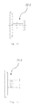
- FIG. 1 is a cross-sectional view illustrating the structure of a conventional self-blast circuit breaker
- FIG. 2 is a cross-sectional view illustrating the actuating rod of the conventional self-blast circuit breaker.
- a self-blast circuit breaker as one kind of a circuit breaker of a gas-insulated switchgear has a puffer chamber 23 and a heat expansion chamber 24, and generally includes three valves.
- the three valves include an intake valve 11 for newly filling an SF6 gas in the puffer chamber 23 upon closing of the circuit breaker, an intake valve 8 for raising the pressure of the heat expansion chamber 24 upon opening of the circuit breaker, and an exhaust valve 15 for removing the unnecessary pressure of the puffer chamber 23.
- the heat expansion chamber 24 becomes a high pressure as a high-temperature insulation gas by the arc generated upon interruption is introduced into the path between a main nozzle 3 and an auxiliary nozzle 4.
- the intake valve 8 is closed.
- the movable parts of the circuit breaker are continuously moved, the volume of the puffer chamber 23 is further decreased, and the pressure of the puffer chamber 23 is further raised. Since the raised pressure cannot be introduced into the heat expansion chamber 24, it is exhausted through the exhaust valve 15.
- the heat expansion chamber 24 discharges a high-pressure insulation gas at an interruption timing and cuts off an arc so as to implement interruption, by using the pressure initially introduced into the puffer chamber 23 and the pressure introduced from the high-temperature and high-pressure energy produced due to the arc generated as a fixed part arc contact 31 and a movable part arc contact 2 are physically separated from each other.
- the interrupting performance of the self-blast circuit breaker is determined according the pressure and the temperature of the insulation gas in the heat expansion chamber 24.
- the pressure should be sufficient to cut off the arc column generated between the fixed part arc contact 31 and the movable part arc contact 2.
- the insulation performance is excellent as the temperature of the insulation gas is low. Therefore, as the insulation gas has a low temperature and a high pressure, the interrupting performance becomes excellent.
- the heat expansion chamber 24 should lower the temperature of the insulation gas by appropriately mixing the low-temperature insulation gas introduced from the puffer chamber 23 and the high-temperature insulation gas introduced between the main nozzle 3 and the auxiliary nozzle 4 due to the arc.
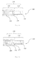
- FIG. 3 is a cross-sectional view illustrating a self-blast circuit breaker reusing arc heat in accordance with an embodiment.
- the self-blast circuit breaker reusing arc heat in accordance with the embodiment has a feature in that it has auxiliary intake valves 100 which introduce the hot gas introduced into an actuating rod 22, into a heat expansion chamber 24.
- Each of the auxiliary intake valves 100 may be formed as a check valve in which an inlet is defined to communicate with the inside of the actuating rod 22 and an outlet is defined to communicate with the inside of the heat expansion chamber 24.
- the hot gas produced by an arc passes through the inside of the actuating rod 22.
- the auxiliary intake valves 100 are opened by such a hog gas, and introduce the hot gas produced by the arc, into the inside of the heat expansion chamber 24, thereby raising the pressure in the heat expansion chamber 24 and improving interrupting performance.
- inlets may be defined to be open toward an arc generation spot.
- FIG. 4 is a cross-sectional view illustrating the actuating rod of the self-blast circuit breaker in accordance with the embodiment
- FIGS. 5a and 5b are views illustrating embodiments of the flange part of the actuating rod in accordance with the embodiment.
- the auxiliary intake valves 100 are mounted to the actuating rod 22.
- the actuating rod 22 may be formed in such a way as to be divided into a rod part 22-1 and a flange part 22-2.
- FIG. 5a illustrates a state in which the pipe of the flange part 22-2 is formed to have a polygonal sectional shape
- FIG. 5b illustrates a state in which only the circumferential portion of the pipe of the flange part 22-2 to be mounted with the auxiliary intake valves 100 is formed to have a polygonal sectional shape.
- the pipe of the flange part 22-2 may be formed to have a circular sectional shape, the mounting of the auxiliary intake valves 100 may be easily carried out when the mounting surfaces of the auxiliary intake valves 100 are formed as flat surfaces as shown in FIGS. 5a and 5b .
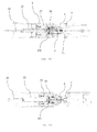
- FIG. 6a is a cross-sectional view illustrating the closed state of the auxiliary intake valve in accordance with the embodiment
- FIG. 6b is a cross-sectional view illustrating the opened state of the auxiliary intake valve in accordance with the embodiment.
- the auxiliary intake valve 100 in accordance with the embodiment includes a valve case 130, and an opening/closing piece 150.
- a small diameter part 110 which has a relatively small inner diameter
- a large diameter part 120 which has a relatively large inner diameter
- An inlet 112 is defined in the small diameter part 110
- an outlet 122 is defined in the large diameter part 120.
- the opening/closing piece 150 may close the small diameter part 110 by the elastic force of an elastic member 140 disposed in the large diameter part 120.
- the opening/closing piece 150 is retracted and the elastic member 140 is compressed. Due to this fact, as the inlet 112 and the outlet 122 communicate with each other, the hot gas introduced through the inlet 112 may be introduced into the heat expansion chamber 24 through the outlet 122.
- FIGS. 7a and 7b are cross-sectional views illustrating the assembled states of auxiliary intake valves in accordance with the embodiment.
- the flange part may be formed into a regular octagonal shape, and eight auxiliary intake valves 100 may be mounted, and, as shown in FIG. 7b , the flange part may be formed into a cylindrical shape, and four auxiliary intake valves 100 may be mounted.
- the sectional shape of the flange part or the number of the auxiliary intake valves 100 may be changed in a variety of ways.
- FIGS. 8a to 8e are cross-sectional views explaining the operations of the self-blast circuit breaker in accordance with the embodiment.
- FIG. 8a illustrates a closed state. If opening is started from the closed state, as shown in FIG. 8b , after the fixed part arc contact 31 and the movable part arc contact 2 are disconnected from each other, compression of the puffer chamber 23 occurs, and the insulation gas is introduced into the heat expansion chamber 24.
- the hot gas by the arc is introduced between the main nozzle 3 and the auxiliary nozzle 4, and the gas is exhausted from the puffer chamber 23.
- the hot gas due to the arc which is exhausted through the inside of the actuating rod 22, is introduced into the heat expansion chamber 24 through the auxiliary intake valves 100.
- the insulation gas of the heat expansion chamber 24 is exhausted through between the main nozzle 3 and the auxiliary nozzle 4, for interruption of current.
- the self-blast circuit breaker according to the embodiment provides advantages in that, since a portion of the hot gas discharged to an actuating rod, of a hot gas by a generated arc, is introduced into a heat expansion chamber, the pressure of the heat expansion chamber may be raised.
- the embodiment has a feature in that auxiliary intake valves are provided in the actuating rod to introduce the high-pressure insulation gas to be exhausted, into the heat expansion chamber.
Landscapes
- Circuit Breakers (AREA)
Applications Claiming Priority (1)
| Application Number | Priority Date | Filing Date | Title |
|---|---|---|---|
| KR1020140042575A KR101763451B1 (ko) | 2014-04-09 | 2014-04-09 | 아크열을 재이용하는 복합소호형 차단기 |
Publications (2)
| Publication Number | Publication Date |
|---|---|
| EP2930731A1 true EP2930731A1 (de) | 2015-10-14 |
| EP2930731B1 EP2930731B1 (de) | 2018-12-26 |
Family
ID=52273031
Family Applications (1)
| Application Number | Title | Priority Date | Filing Date |
|---|---|---|---|
| EP15150352.1A Active EP2930731B1 (de) | 2014-04-09 | 2015-01-07 | Selbstblasschalter mit Verwendung von Lichtbogenwärme |
Country Status (4)
| Country | Link |
|---|---|
| US (1) | US9496107B2 (de) |
| EP (1) | EP2930731B1 (de) |
| KR (1) | KR101763451B1 (de) |
| CN (1) | CN104979128B (de) |
Families Citing this family (10)
| Publication number | Priority date | Publication date | Assignee | Title |
|---|---|---|---|---|
| JP6478836B2 (ja) * | 2015-06-29 | 2019-03-06 | 株式会社東芝 | ガス遮断器 |
| US9865418B2 (en) * | 2015-12-08 | 2018-01-09 | Siemens Industry, Inc. | Circuit breakers, arc expansion chambers, and operating methods |
| CN106356266B (zh) * | 2016-11-24 | 2019-03-12 | 河南平芝高压开关有限公司 | 一种灭弧室及使用该灭弧室的断路器 |
| CN108447711B (zh) * | 2018-01-31 | 2020-05-15 | 河南平高电气股份有限公司 | 缓冲装置、操动机构及高压开关 |
| CN108744172B (zh) * | 2018-04-04 | 2020-10-23 | 孟蓓蓓 | 一种手术室输血输液护理加温装置 |
| CN111668061B (zh) * | 2019-03-05 | 2022-12-09 | 国家电网有限公司 | 一种灭弧室阀座及灭弧室 |
| DE102019213344A1 (de) * | 2019-09-03 | 2021-03-04 | Siemens Energy Global GmbH & Co. KG | Unterteilen eines Heizvolumens eines Leistungsschalters |
| US11380501B2 (en) | 2019-12-31 | 2022-07-05 | Southern States Llc | High voltage electric power switch with carbon arcing electrodes and carbon dioxide dielectric gas |
| CA3140003A1 (en) * | 2020-11-20 | 2022-05-20 | Technologies Mindcore Inc. | System for controlling and cooling gas of circuit breaker and method thereof |
| CN114141574B (zh) * | 2021-10-20 | 2024-03-26 | 平高集团有限公司 | 一种断路器及其主拉杆 |
Citations (4)
| Publication number | Priority date | Publication date | Assignee | Title |
|---|---|---|---|---|
| US4598188A (en) * | 1983-11-15 | 1986-07-01 | Sprecher & Schuh Ag | Gas-blast switch |
| US4684773A (en) * | 1984-10-10 | 1987-08-04 | Bbc Brown, Boveri & Company, Limited | Gas-blast switch |
| DE19859764A1 (de) * | 1998-12-23 | 2000-06-29 | Abb Research Ltd | Selbstblasschalter |
| KR20120002779A (ko) | 2010-07-01 | 2012-01-09 | 현대중공업 주식회사 | 가스절연개폐장치용 복합 소호형 가스차단기 |
Family Cites Families (14)
| Publication number | Priority date | Publication date | Assignee | Title |
|---|---|---|---|---|
| DE2411897A1 (de) * | 1974-03-12 | 1975-09-18 | Siemens Ag | Anordnung zur loeschung eines lichtbogens in einem gasstroemungsschalter |
| US4665289A (en) * | 1985-05-08 | 1987-05-12 | Kabushiki Kaisha Toshiba | Puffer type gas insulated circuit breaker |
| JPH02247929A (ja) | 1989-03-20 | 1990-10-03 | Meidensha Corp | パッファ形ガス遮断器 |
| FR2647255B1 (fr) * | 1989-05-17 | 1993-04-23 | Alsthom Gec | Disjoncteur a haute tension a gaz dielectrique de soufflage |
| DE9308586U1 (de) * | 1993-06-04 | 1993-11-04 | Siemens AG, 80333 München | Elektrischer Hochspannungsleistungsschalter |
| JP3183120B2 (ja) * | 1995-09-20 | 2001-07-03 | 株式会社日立製作所 | 遮断器の流体圧駆動装置およびこれを用いた遮断器 |
| JP4174094B2 (ja) * | 1998-01-29 | 2008-10-29 | 株式会社東芝 | ガス遮断器 |
| JP2004119344A (ja) * | 2002-09-30 | 2004-04-15 | Mitsubishi Electric Corp | ガス遮断器 |
| FR2892851B1 (fr) * | 2005-11-03 | 2013-12-06 | Areva T & D Sa | Chambre de coupure de courant a double chambre de compression |
| KR200412367Y1 (ko) * | 2005-12-30 | 2006-03-27 | 숭의기업주식회사 | 과압 방지장치를 구비한 알람 체크밸브 |
| EP1939910A1 (de) * | 2006-12-27 | 2008-07-02 | ABB Technology AG | Druckgasschalter mit einer radialen Durchströmöffnung |
| FR2922043B1 (fr) * | 2007-10-03 | 2009-12-11 | Areva T & D Sa | Chambre de coupure de disjoncteur a double volume de compression |
| FR2947377B1 (fr) * | 2009-06-29 | 2011-07-22 | Areva T & D Sa | Valve a clapet de decharge destinee a decharger un gaz dielectrique entre deux volumes d'une chambre de coupure de disjoncteur haute ou moyenne tension |
| JP5516568B2 (ja) * | 2011-12-28 | 2014-06-11 | 株式会社日立製作所 | パッファ形ガス遮断器 |
-
2014
- 2014-04-09 KR KR1020140042575A patent/KR101763451B1/ko active IP Right Grant
- 2014-12-19 US US14/577,508 patent/US9496107B2/en active Active
-
2015
- 2015-01-06 CN CN201510006205.5A patent/CN104979128B/zh active Active
- 2015-01-07 EP EP15150352.1A patent/EP2930731B1/de active Active
Patent Citations (4)
| Publication number | Priority date | Publication date | Assignee | Title |
|---|---|---|---|---|
| US4598188A (en) * | 1983-11-15 | 1986-07-01 | Sprecher & Schuh Ag | Gas-blast switch |
| US4684773A (en) * | 1984-10-10 | 1987-08-04 | Bbc Brown, Boveri & Company, Limited | Gas-blast switch |
| DE19859764A1 (de) * | 1998-12-23 | 2000-06-29 | Abb Research Ltd | Selbstblasschalter |
| KR20120002779A (ko) | 2010-07-01 | 2012-01-09 | 현대중공업 주식회사 | 가스절연개폐장치용 복합 소호형 가스차단기 |
Also Published As
| Publication number | Publication date |
|---|---|
| KR20150117364A (ko) | 2015-10-20 |
| KR101763451B1 (ko) | 2017-08-01 |
| EP2930731B1 (de) | 2018-12-26 |
| CN104979128B (zh) | 2017-11-17 |
| CN104979128A (zh) | 2015-10-14 |
| US20150294820A1 (en) | 2015-10-15 |
| US9496107B2 (en) | 2016-11-15 |
Similar Documents
| Publication | Publication Date | Title |
|---|---|---|
| US9496107B2 (en) | Self-blast circuit breaker reusing arc heat | |
| CN100530480C (zh) | 一种新型单断口电压至252kV的高压真空断路器 | |
| CN104145318B (zh) | 一种带有固定断口的真空灭弧室 | |
| JP2013140693A (ja) | パッファ形ガス遮断器 | |
| KR101657454B1 (ko) | 가스절연 차단기 | |
| KR101605601B1 (ko) | 고정부의 길이를 축소한 가스절연 개폐장치의 차단기 | |
| KR101972872B1 (ko) | 아크 에너지 활용율을 향상시킨 가스절연 개폐장치의 차단기 | |
| KR101621138B1 (ko) | 차단성능을 향상시킨 가스절연 개폐장치의 차단기 | |
| US9384924B2 (en) | Gas circuit breaker | |
| KR101291789B1 (ko) | 가스절연개폐장치 | |
| JP4879366B1 (ja) | ガス遮断器 | |
| KR101701817B1 (ko) | 가스절연 차단기 | |
| CN110770868B (zh) | 气体绝缘负载断路开关和包括气体绝缘负载断路开关的开关设备 | |
| US10170256B2 (en) | Circuit breaker equipped with an extensible exhaust cover | |
| WO2018066119A1 (ja) | ガス遮断器 | |
| KR102466938B1 (ko) | 가스절연 개폐장치용 가스 차단기 | |
| KR101296893B1 (ko) | 가스절연개폐장치 | |
| KR20230102114A (ko) | 가스 절연 개폐 장치용 접지 개폐기 | |
| KR101296894B1 (ko) | 가스절연개폐장치 | |
| KR20150009761A (ko) | 열팽창실의 이중압축 구조를 구비하는 가스절연개폐장치의 차단기 | |
| RU2396629C2 (ru) | Дугогасительное устройство высоковольтного газонаполненного автокомпрессионного выключателя | |
| JPH103834A (ja) | パッファ式ガス遮断器 | |
| KR20160031571A (ko) | 열팽창실 가스 흐름을 개선한 복합소호형 가스절연 차단기 | |
| JPH01102825A (ja) | パッファ形ガス遮断器 | |
| KR20150092871A (ko) | 아크 접점의 열손상을 방지한 가스절연개폐장치의 차단기 |
Legal Events
| Date | Code | Title | Description |
|---|---|---|---|
| PUAI | Public reference made under article 153(3) epc to a published international application that has entered the european phase |
Free format text: ORIGINAL CODE: 0009012 |
|
| 17P | Request for examination filed |
Effective date: 20150107 |
|
| AK | Designated contracting states |
Kind code of ref document: A1 Designated state(s): AL AT BE BG CH CY CZ DE DK EE ES FI FR GB GR HR HU IE IS IT LI LT LU LV MC MK MT NL NO PL PT RO RS SE SI SK SM TR |
|
| AX | Request for extension of the european patent |
Extension state: BA ME |
|
| RAP1 | Party data changed (applicant data changed or rights of an application transferred) |
Owner name: HYUNDAI ELECTRIC & ENERGY SYSTEMS CO., LTD. |
|
| GRAP | Despatch of communication of intention to grant a patent |
Free format text: ORIGINAL CODE: EPIDOSNIGR1 |
|
| STAA | Information on the status of an ep patent application or granted ep patent |
Free format text: STATUS: GRANT OF PATENT IS INTENDED |
|
| RIC1 | Information provided on ipc code assigned before grant |
Ipc: H01H 33/90 20060101ALN20180627BHEP Ipc: H01H 33/88 20060101ALN20180627BHEP Ipc: H01H 33/72 20060101AFI20180627BHEP |
|
| INTG | Intention to grant announced |
Effective date: 20180719 |
|
| RIN1 | Information on inventor provided before grant (corrected) |
Inventor name: KIM, HYUNG-CHOON |
|
| GRAS | Grant fee paid |
Free format text: ORIGINAL CODE: EPIDOSNIGR3 |
|
| GRAA | (expected) grant |
Free format text: ORIGINAL CODE: 0009210 |
|
| STAA | Information on the status of an ep patent application or granted ep patent |
Free format text: STATUS: THE PATENT HAS BEEN GRANTED |
|
| AK | Designated contracting states |
Kind code of ref document: B1 Designated state(s): AL AT BE BG CH CY CZ DE DK EE ES FI FR GB GR HR HU IE IS IT LI LT LU LV MC MK MT NL NO PL PT RO RS SE SI SK SM TR |
|
| REG | Reference to a national code |
Ref country code: GB Ref legal event code: FG4D |
|
| REG | Reference to a national code |
Ref country code: CH Ref legal event code: EP |
|
| REG | Reference to a national code |
Ref country code: AT Ref legal event code: REF Ref document number: 1082578 Country of ref document: AT Kind code of ref document: T Effective date: 20190115 |
|
| REG | Reference to a national code |
Ref country code: DE Ref legal event code: R096 Ref document number: 602015022086 Country of ref document: DE |
|
| REG | Reference to a national code |
Ref country code: IE Ref legal event code: FG4D |
|
| REG | Reference to a national code |
Ref country code: CH Ref legal event code: NV Representative=s name: VALIPAT S.A. GEVERS SA, CH |
|
| REG | Reference to a national code |
Ref country code: CH Ref legal event code: PCAR Free format text: NEW ADDRESS: RUE DES NOYERS 11, 2000 NEUCHATEL (CH) |
|
| PG25 | Lapsed in a contracting state [announced via postgrant information from national office to epo] |
Ref country code: FI Free format text: LAPSE BECAUSE OF FAILURE TO SUBMIT A TRANSLATION OF THE DESCRIPTION OR TO PAY THE FEE WITHIN THE PRESCRIBED TIME-LIMIT Effective date: 20181226 Ref country code: LV Free format text: LAPSE BECAUSE OF FAILURE TO SUBMIT A TRANSLATION OF THE DESCRIPTION OR TO PAY THE FEE WITHIN THE PRESCRIBED TIME-LIMIT Effective date: 20181226 Ref country code: HR Free format text: LAPSE BECAUSE OF FAILURE TO SUBMIT A TRANSLATION OF THE DESCRIPTION OR TO PAY THE FEE WITHIN THE PRESCRIBED TIME-LIMIT Effective date: 20181226 Ref country code: BG Free format text: LAPSE BECAUSE OF FAILURE TO SUBMIT A TRANSLATION OF THE DESCRIPTION OR TO PAY THE FEE WITHIN THE PRESCRIBED TIME-LIMIT Effective date: 20190326 Ref country code: NO Free format text: LAPSE BECAUSE OF FAILURE TO SUBMIT A TRANSLATION OF THE DESCRIPTION OR TO PAY THE FEE WITHIN THE PRESCRIBED TIME-LIMIT Effective date: 20190326 Ref country code: LT Free format text: LAPSE BECAUSE OF FAILURE TO SUBMIT A TRANSLATION OF THE DESCRIPTION OR TO PAY THE FEE WITHIN THE PRESCRIBED TIME-LIMIT Effective date: 20181226 |
|
| REG | Reference to a national code |
Ref country code: NL Ref legal event code: MP Effective date: 20181226 |
|
| REG | Reference to a national code |
Ref country code: LT Ref legal event code: MG4D |
|
| PG25 | Lapsed in a contracting state [announced via postgrant information from national office to epo] |
Ref country code: AL Free format text: LAPSE BECAUSE OF FAILURE TO SUBMIT A TRANSLATION OF THE DESCRIPTION OR TO PAY THE FEE WITHIN THE PRESCRIBED TIME-LIMIT Effective date: 20181226 Ref country code: GR Free format text: LAPSE BECAUSE OF FAILURE TO SUBMIT A TRANSLATION OF THE DESCRIPTION OR TO PAY THE FEE WITHIN THE PRESCRIBED TIME-LIMIT Effective date: 20190327 Ref country code: RS Free format text: LAPSE BECAUSE OF FAILURE TO SUBMIT A TRANSLATION OF THE DESCRIPTION OR TO PAY THE FEE WITHIN THE PRESCRIBED TIME-LIMIT Effective date: 20181226 Ref country code: SE Free format text: LAPSE BECAUSE OF FAILURE TO SUBMIT A TRANSLATION OF THE DESCRIPTION OR TO PAY THE FEE WITHIN THE PRESCRIBED TIME-LIMIT Effective date: 20181226 |
|
| REG | Reference to a national code |
Ref country code: AT Ref legal event code: MK05 Ref document number: 1082578 Country of ref document: AT Kind code of ref document: T Effective date: 20181226 |
|
| PG25 | Lapsed in a contracting state [announced via postgrant information from national office to epo] |
Ref country code: NL Free format text: LAPSE BECAUSE OF FAILURE TO SUBMIT A TRANSLATION OF THE DESCRIPTION OR TO PAY THE FEE WITHIN THE PRESCRIBED TIME-LIMIT Effective date: 20181226 |
|
| PG25 | Lapsed in a contracting state [announced via postgrant information from national office to epo] |
Ref country code: CZ Free format text: LAPSE BECAUSE OF FAILURE TO SUBMIT A TRANSLATION OF THE DESCRIPTION OR TO PAY THE FEE WITHIN THE PRESCRIBED TIME-LIMIT Effective date: 20181226 Ref country code: IT Free format text: LAPSE BECAUSE OF FAILURE TO SUBMIT A TRANSLATION OF THE DESCRIPTION OR TO PAY THE FEE WITHIN THE PRESCRIBED TIME-LIMIT Effective date: 20181226 Ref country code: ES Free format text: LAPSE BECAUSE OF FAILURE TO SUBMIT A TRANSLATION OF THE DESCRIPTION OR TO PAY THE FEE WITHIN THE PRESCRIBED TIME-LIMIT Effective date: 20181226 Ref country code: PT Free format text: LAPSE BECAUSE OF FAILURE TO SUBMIT A TRANSLATION OF THE DESCRIPTION OR TO PAY THE FEE WITHIN THE PRESCRIBED TIME-LIMIT Effective date: 20190426 Ref country code: PL Free format text: LAPSE BECAUSE OF FAILURE TO SUBMIT A TRANSLATION OF THE DESCRIPTION OR TO PAY THE FEE WITHIN THE PRESCRIBED TIME-LIMIT Effective date: 20181226 |
|
| REG | Reference to a national code |
Ref country code: DE Ref legal event code: R119 Ref document number: 602015022086 Country of ref document: DE |
|
| PG25 | Lapsed in a contracting state [announced via postgrant information from national office to epo] |
Ref country code: EE Free format text: LAPSE BECAUSE OF FAILURE TO SUBMIT A TRANSLATION OF THE DESCRIPTION OR TO PAY THE FEE WITHIN THE PRESCRIBED TIME-LIMIT Effective date: 20181226 Ref country code: SM Free format text: LAPSE BECAUSE OF FAILURE TO SUBMIT A TRANSLATION OF THE DESCRIPTION OR TO PAY THE FEE WITHIN THE PRESCRIBED TIME-LIMIT Effective date: 20181226 Ref country code: SK Free format text: LAPSE BECAUSE OF FAILURE TO SUBMIT A TRANSLATION OF THE DESCRIPTION OR TO PAY THE FEE WITHIN THE PRESCRIBED TIME-LIMIT Effective date: 20181226 Ref country code: RO Free format text: LAPSE BECAUSE OF FAILURE TO SUBMIT A TRANSLATION OF THE DESCRIPTION OR TO PAY THE FEE WITHIN THE PRESCRIBED TIME-LIMIT Effective date: 20181226 Ref country code: IS Free format text: LAPSE BECAUSE OF FAILURE TO SUBMIT A TRANSLATION OF THE DESCRIPTION OR TO PAY THE FEE WITHIN THE PRESCRIBED TIME-LIMIT Effective date: 20190426 |
|
| PG25 | Lapsed in a contracting state [announced via postgrant information from national office to epo] |
Ref country code: LU Free format text: LAPSE BECAUSE OF NON-PAYMENT OF DUE FEES Effective date: 20190107 |
|
| REG | Reference to a national code |
Ref country code: BE Ref legal event code: MM Effective date: 20190131 |
|
| REG | Reference to a national code |
Ref country code: IE Ref legal event code: MM4A |
|
| PG25 | Lapsed in a contracting state [announced via postgrant information from national office to epo] |
Ref country code: DE Free format text: LAPSE BECAUSE OF NON-PAYMENT OF DUE FEES Effective date: 20190801 Ref country code: MC Free format text: LAPSE BECAUSE OF FAILURE TO SUBMIT A TRANSLATION OF THE DESCRIPTION OR TO PAY THE FEE WITHIN THE PRESCRIBED TIME-LIMIT Effective date: 20181226 Ref country code: AT Free format text: LAPSE BECAUSE OF FAILURE TO SUBMIT A TRANSLATION OF THE DESCRIPTION OR TO PAY THE FEE WITHIN THE PRESCRIBED TIME-LIMIT Effective date: 20181226 Ref country code: DK Free format text: LAPSE BECAUSE OF FAILURE TO SUBMIT A TRANSLATION OF THE DESCRIPTION OR TO PAY THE FEE WITHIN THE PRESCRIBED TIME-LIMIT Effective date: 20181226 |
|
| PLBE | No opposition filed within time limit |
Free format text: ORIGINAL CODE: 0009261 |
|
| STAA | Information on the status of an ep patent application or granted ep patent |
Free format text: STATUS: NO OPPOSITION FILED WITHIN TIME LIMIT |
|
| GBPC | Gb: european patent ceased through non-payment of renewal fee |
Effective date: 20190326 |
|
| PG25 | Lapsed in a contracting state [announced via postgrant information from national office to epo] |
Ref country code: BE Free format text: LAPSE BECAUSE OF NON-PAYMENT OF DUE FEES Effective date: 20190131 |
|
| 26N | No opposition filed |
Effective date: 20190927 |
|
| PG25 | Lapsed in a contracting state [announced via postgrant information from national office to epo] |
Ref country code: GB Free format text: LAPSE BECAUSE OF NON-PAYMENT OF DUE FEES Effective date: 20190326 Ref country code: IE Free format text: LAPSE BECAUSE OF NON-PAYMENT OF DUE FEES Effective date: 20190107 |
|
| PG25 | Lapsed in a contracting state [announced via postgrant information from national office to epo] |
Ref country code: FR Free format text: LAPSE BECAUSE OF NON-PAYMENT OF DUE FEES Effective date: 20190226 Ref country code: SI Free format text: LAPSE BECAUSE OF FAILURE TO SUBMIT A TRANSLATION OF THE DESCRIPTION OR TO PAY THE FEE WITHIN THE PRESCRIBED TIME-LIMIT Effective date: 20181226 |
|
| PG25 | Lapsed in a contracting state [announced via postgrant information from national office to epo] |
Ref country code: TR Free format text: LAPSE BECAUSE OF FAILURE TO SUBMIT A TRANSLATION OF THE DESCRIPTION OR TO PAY THE FEE WITHIN THE PRESCRIBED TIME-LIMIT Effective date: 20181226 |
|
| PG25 | Lapsed in a contracting state [announced via postgrant information from national office to epo] |
Ref country code: MT Free format text: LAPSE BECAUSE OF NON-PAYMENT OF DUE FEES Effective date: 20190107 |
|
| PG25 | Lapsed in a contracting state [announced via postgrant information from national office to epo] |
Ref country code: CY Free format text: LAPSE BECAUSE OF FAILURE TO SUBMIT A TRANSLATION OF THE DESCRIPTION OR TO PAY THE FEE WITHIN THE PRESCRIBED TIME-LIMIT Effective date: 20181226 |
|
| PG25 | Lapsed in a contracting state [announced via postgrant information from national office to epo] |
Ref country code: HU Free format text: LAPSE BECAUSE OF FAILURE TO SUBMIT A TRANSLATION OF THE DESCRIPTION OR TO PAY THE FEE WITHIN THE PRESCRIBED TIME-LIMIT; INVALID AB INITIO Effective date: 20150107 |
|
| PG25 | Lapsed in a contracting state [announced via postgrant information from national office to epo] |
Ref country code: MK Free format text: LAPSE BECAUSE OF FAILURE TO SUBMIT A TRANSLATION OF THE DESCRIPTION OR TO PAY THE FEE WITHIN THE PRESCRIBED TIME-LIMIT Effective date: 20181226 |
|
| PGFP | Annual fee paid to national office [announced via postgrant information from national office to epo] |
Ref country code: CH Payment date: 20240202 Year of fee payment: 10 |