EP2930522A1 - Method and device for spatially resolved diagnosis - Google Patents
Method and device for spatially resolved diagnosis Download PDFInfo
- Publication number
- EP2930522A1 EP2930522A1 EP15163140.5A EP15163140A EP2930522A1 EP 2930522 A1 EP2930522 A1 EP 2930522A1 EP 15163140 A EP15163140 A EP 15163140A EP 2930522 A1 EP2930522 A1 EP 2930522A1
- Authority
- EP
- European Patent Office
- Prior art keywords
- pulses
- operating means
- evaluation unit
- pulse
- cable
- Prior art date
- Legal status (The legal status is an assumption and is not a legal conclusion. Google has not performed a legal analysis and makes no representation as to the accuracy of the status listed.)
- Granted
Links
- 238000000034 method Methods 0.000 title claims abstract description 65
- 238000003745 diagnosis Methods 0.000 title claims abstract description 27
- 238000011156 evaluation Methods 0.000 claims abstract description 44
- 238000002592 echocardiography Methods 0.000 claims abstract description 5
- 238000004364 calculation method Methods 0.000 claims abstract description 4
- 230000002452 interceptive effect Effects 0.000 claims abstract 2
- 238000005259 measurement Methods 0.000 claims description 31
- 238000004088 simulation Methods 0.000 claims description 8
- 238000005070 sampling Methods 0.000 claims description 3
- 238000001208 nuclear magnetic resonance pulse sequence Methods 0.000 claims 2
- 230000005540 biological transmission Effects 0.000 abstract description 5
- 230000001066 destructive effect Effects 0.000 description 13
- 230000008878 coupling Effects 0.000 description 7
- 238000010168 coupling process Methods 0.000 description 7
- 238000005859 coupling reaction Methods 0.000 description 7
- 238000002310 reflectometry Methods 0.000 description 7
- 230000001419 dependent effect Effects 0.000 description 6
- 208000028659 discharge Diseases 0.000 description 6
- 238000000691 measurement method Methods 0.000 description 6
- 238000001514 detection method Methods 0.000 description 5
- 230000002349 favourable effect Effects 0.000 description 5
- 230000036961 partial effect Effects 0.000 description 5
- 238000011161 development Methods 0.000 description 4
- 230000018109 developmental process Effects 0.000 description 4
- 238000002405 diagnostic procedure Methods 0.000 description 4
- 238000010586 diagram Methods 0.000 description 4
- 238000004458 analytical method Methods 0.000 description 3
- 230000007547 defect Effects 0.000 description 3
- 230000002950 deficient Effects 0.000 description 3
- 239000006185 dispersion Substances 0.000 description 3
- 238000009826 distribution Methods 0.000 description 3
- 230000004807 localization Effects 0.000 description 3
- 230000008901 benefit Effects 0.000 description 2
- 238000004422 calculation algorithm Methods 0.000 description 2
- 238000012937 correction Methods 0.000 description 2
- 230000006866 deterioration Effects 0.000 description 2
- 238000012545 processing Methods 0.000 description 2
- 238000001228 spectrum Methods 0.000 description 2
- 238000010183 spectrum analysis Methods 0.000 description 2
- 230000002123 temporal effect Effects 0.000 description 2
- 238000012360 testing method Methods 0.000 description 2
- 238000012546 transfer Methods 0.000 description 2
- 235000006679 Mentha X verticillata Nutrition 0.000 description 1
- 235000002899 Mentha suaveolens Nutrition 0.000 description 1
- 235000001636 Mentha x rotundifolia Nutrition 0.000 description 1
- 230000006978 adaptation Effects 0.000 description 1
- 230000032683 aging Effects 0.000 description 1
- 230000002238 attenuated effect Effects 0.000 description 1
- 238000005311 autocorrelation function Methods 0.000 description 1
- 239000011248 coating agent Substances 0.000 description 1
- 238000000576 coating method Methods 0.000 description 1
- 238000010276 construction Methods 0.000 description 1
- 230000003247 decreasing effect Effects 0.000 description 1
- 238000013461 design Methods 0.000 description 1
- 230000007613 environmental effect Effects 0.000 description 1
- 230000007274 generation of a signal involved in cell-cell signaling Effects 0.000 description 1
- 238000009413 insulation Methods 0.000 description 1
- 230000010354 integration Effects 0.000 description 1
- 230000000670 limiting effect Effects 0.000 description 1
- 238000012423 maintenance Methods 0.000 description 1
- 230000028161 membrane depolarization Effects 0.000 description 1
- 230000003287 optical effect Effects 0.000 description 1
- 230000003449 preventive effect Effects 0.000 description 1
- 238000004886 process control Methods 0.000 description 1
- 238000004393 prognosis Methods 0.000 description 1
- 230000009467 reduction Effects 0.000 description 1
- 230000002829 reductive effect Effects 0.000 description 1
- 230000011664 signaling Effects 0.000 description 1
- 230000035882 stress Effects 0.000 description 1
- 238000003325 tomography Methods 0.000 description 1
- 230000009466 transformation Effects 0.000 description 1
Images


Classifications
-
- G—PHYSICS
- G01—MEASURING; TESTING
- G01R—MEASURING ELECTRIC VARIABLES; MEASURING MAGNETIC VARIABLES
- G01R31/00—Arrangements for testing electric properties; Arrangements for locating electric faults; Arrangements for electrical testing characterised by what is being tested not provided for elsewhere
- G01R31/001—Measuring interference from external sources to, or emission from, the device under test, e.g. EMC, EMI, EMP or ESD testing
-
- G—PHYSICS
- G01—MEASURING; TESTING
- G01R—MEASURING ELECTRIC VARIABLES; MEASURING MAGNETIC VARIABLES
- G01R31/00—Arrangements for testing electric properties; Arrangements for locating electric faults; Arrangements for electrical testing characterised by what is being tested not provided for elsewhere
- G01R31/08—Locating faults in cables, transmission lines, or networks
- G01R31/081—Locating faults in cables, transmission lines, or networks according to type of conductors
- G01R31/083—Locating faults in cables, transmission lines, or networks according to type of conductors in cables, e.g. underground
-
- G—PHYSICS
- G01—MEASURING; TESTING
- G01R—MEASURING ELECTRIC VARIABLES; MEASURING MAGNETIC VARIABLES
- G01R31/00—Arrangements for testing electric properties; Arrangements for locating electric faults; Arrangements for electrical testing characterised by what is being tested not provided for elsewhere
- G01R31/08—Locating faults in cables, transmission lines, or networks
- G01R31/11—Locating faults in cables, transmission lines, or networks using pulse reflection methods
-
- G—PHYSICS
- G01—MEASURING; TESTING
- G01R—MEASURING ELECTRIC VARIABLES; MEASURING MAGNETIC VARIABLES
- G01R31/00—Arrangements for testing electric properties; Arrangements for locating electric faults; Arrangements for electrical testing characterised by what is being tested not provided for elsewhere
- G01R31/50—Testing of electric apparatus, lines, cables or components for short-circuits, continuity, leakage current or incorrect line connections
- G01R31/58—Testing of lines, cables or conductors
Definitions
- the invention firstly relates to a method for the spatially resolved diagnosis of the electrical state of a spatially extended operating means, in particular of a cable for transmitting electrical energy, by means of interference between pulses fed into the operating means by a signal generator.
- the invention has a device for the spatially resolved diagnosis of an electrical condition of a spatially extended operating means, in particular a cable for transmitting electrical energy, by means of interference between at least two by a pulse interval .DELTA.t staggered pulses fed into the resource.
- partial discharge diagnosis In the partial discharge diagnosis mentioned at the beginning (so-called "TE" diagnosis (partial discharge diagnosis) partial discharge defects are recognized, evaluated and localized.)
- TE diagnosis partial discharge diagnosis
- the voltage load during the measurement is greater than the nominal voltage in order to obtain a reliable state prognosis of the cable at all
- high voltage stress can cause additional aging or damage to the cable to be diagnosed
- a spatial localization of a main discharge point is possible, but by multiple defects, high cable lengths with correspondingly high attenuation or moisture in the K Abel, a localization is much more difficult.
- the measurement is made using high voltage applied to the cable. Subsequently, measuring voltages are measured by means of a voltage detection device and individual currents to be assigned to the measuring objects by means of the at least two current detection devices and evaluated in an evaluation unit.
- frequency domain reflectometry Frequency Domain Reflectometry method
- FDR method Frequency Domain Reflectometry method
- JTFDR Joint Time Frequency Domain Reflectometry
- a disadvantage of this previously known method is the fact that in turn only changes in the impedance or the frequency spectrum are detectable and evaluable.
- the US 2008/0048668 A1 further discloses diagnostic methods for electrical cables using axial tomography.
- the cable to be examined at the beginning and at the end connected in a suitable manner which z. B. by a variable voltage, an internal resistance, a variable frequency, a load impedance or the like can be done, and so generates a standing wave.
- balance equations can be established which, by varying the input parameters N times, produce a system of equations which theoretically determines all line parameters at any point of the cable.
- An object of the invention is therefore to provide a method for spatially resolved electrical diagnosis of a spatially extended equipment, in particular a high-voltage cable for energy transmission.
- an object of the invention is to provide a mobile and at the same time easy-to-use device for carrying out the method.
- the method allows sufficiently reliable statements about local qualitative properties, so that the probability of failure of precisely defined cable segments or cable sections can be predicted with additional expert knowledge. Due to the comparatively low measurement effort, the method can also be used for cable measurements in the field, i. H. be used on site.
- the form of the pulses can basically have an arbitrary temporal course.
- local energy losses eW (x) over the length l of the cable are determined mathematically in method step e) for spatially resolved diagnosis using a plurality of interference voltage profiles and voltage profiles produced by the pulses, wherein the voltage profiles are digitized by means of the evaluation unit and calculated an error-free simulation of the equipment.
- interference-free voltage waveforms can be related to the interference voltage waveforms to optimize the evaluation.
- the digital evaluation unit a recording and computational evaluation of the recorded voltage waveforms from the analog-to-digital converter in real time is possible.
- both the constructive interference between the pulse pairs fed into the cable and / or their destructive interference can be exploited.
- pulses and pulse trains are generated with a maximum amplitude of up to 1,000 volts.
- the pulses used can, for. B. have a rectangular, trapezoidal, triangular, sawtooth, sinusoidal, sin (x) / x-shaped, exponential, semi-circular, semi-elliptic, gefonnet rectangular, bell-shaped (Gaussian) pulse shape or any combination of at least two of said pulse shapes.
- the fenestrated rectangular pulses can, for. B. in the manner of "Hamming", “Blackman”, “Harris”, “Kaiser” or "trained by Hann".
- the diagnostic possibilities of the measuring method according to the invention are optimized.
- a dispersion correction can also be carried out.
- the length 1 of the operating means by means of the digital evaluation unit and the signal generator, in particular by means of a transit time measurement of at least one pulse detected.
- the length l of the device to be diagnosed is possible.
- the knowledge of precise length l is necessary, inter alia, in order to influence the pulse spacing .DELTA.t of the pulses fed into the cable in such a way that they interfere with each other at a point x to be examined or that interference occurs at all. Due to the successive variation of the pulse interval ⁇ t of the pulse pairs fed into the cable, the cable can be precisely scanned over its entire length l and electrically evaluated. Alternatively, the determination of the total length of the equipment can also be carried out by means of known TDR methods, FDR methods or a combination thereof.
- the spatially resolved diagnosis of the electrical state of the cable takes place fully automatically under preferred control of the digital evaluation unit and / or manually.
- the diagnostic possibilities of the measuring method according to the invention are considerably expanded.
- the shape of the pulses can in this case have an arbitrary time course and z. B. rectangular, trapezoidal, triangular, sinusoidal, bell-shaped (Gaussian) or be formed with an overlay of such geometries. Additionally or alternatively, the pulses can also be formed by the piecemeal assembly of different geometries.
- the pulses can z. B. with respect to their center (tW / 2) be asymmetric.
- the pulse shape also causes the dispersion correction.
- the signal generator generates pulses which are rectangular in a section of the extended equipment or cable of interest, in particular in the section to be examined, but at the beginning of which have a different shape. This is only limited because the overlapping pulses have different run lengths.
- the voltage profiles can be digitized by means of the evaluation unit and computationally put into relation to an error-free simulation of the equipment.
- the signal generator is followed by a filter system and a variable impedance, wherein the adjustable impedance with a beginning of the resource connected is.
- the evaluation unit is assigned a measuring device, in particular an analog-digital converter, and at least one digital computing unit.
- the voltage waveforms and their echoes can be detected and evaluated with high accuracy in real time.
- at least one screen is provided as an optical output unit.
- the evaluation unit can also have a printer.
- the evaluation unit and an acoustic signaling device such. B. a speaker for the output of beeps and / or be assigned by beeps for certain operating conditions or error messages and / or a voice output.
- one end of the equipment is open or terminated with an impedance Z.
- the interference of the pulses fed into the operating medium can be influenced.
- the pulses fed into the operating medium can interact with one another by means of constructive or destructive interference.
- a length 1 of the operating means by means of the evaluation unit and the signal generator, in particular by means of a transit time measurement with at least one pulse detectable.
- the method exploits the interference characteristics of traveling electrical waves in order to enable a spatially resolved diagnosis of a spatially primarily extended in his longitudinal resources, in particular a cable for energy transfer, and to describe the properties of the dielectric with high accuracy qualitatively.
- equipment spatially extended in its longitudinal direction primarily refers to single or multi-core power supply cables of all voltage levels, including any necessary coupling and connection elements, such as, for example, As sleeves and the like understood.
- a multiplicity of traveling-wave-forming pulse pairs are fed into the equipment or cable to be examined.
- the pulses causing the traveling waves propagate in the equipment to be examined at a finite speed v and are attenuated and distorted by line-related losses.
- a traveling wave in this case consists of a discrete-time signal, which is interpreted as a pulse with a defined amplitude, pulse width tW and -form. These sizes are variable and dependent on the cable to be diagnosed.
- the voltage or current profile at the input or output of the cable is measured. This procedure is initially similar to time domain reflectometry or time domain reflectometry (TDR).
- not a single pulse or jump is generated, but always a pulse pair with a defined pulse interval ⁇ t.
- These pulses are fed from one or both sides.
- the pulse pairs should meet at a specific point x, which results from the previously defined pulse spacing, in the propagation medium. In this case: 0 ⁇ x ⁇ l, where 1 is the total length of the equipment to be examined. If one first considers the one-sided feed, this can be achieved by feeding in a pulse pair at the beginning of the line and the line end being "open". Thus, at the end of a reflection of the traveling waves or the pulse pair - wherein the reflection factor of the voltage at the open end of the cable is one - and there is a returning wave.
- the returning traveling wave or the first pulse and the second still trailing wave or the second pulse meet in the resource or the cable at the point x, which is dependent on the pulse interval and the propagation velocity.
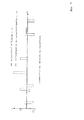
- Fig. 1 to 3 For example, various energy losses are shown within a resource to be diagnosed by the method, which has changed dielectric properties in a range.
- the medium to be examined In order to determine the dielectric properties as a function of the location, the medium to be examined must be scanned across its entire length l with the aid of the method according to the invention. This is done by changing the pulse interval .DELTA.t of the two pulses fed or the pulse pair.
- the total transit time tTransit or tPurchlauf of the pulses must be determined by the resource, which is dependent on the propagation speed and length of the resource, respectively. This can be done for example by means of a reflection measurement in the time domain or in the frequency domain, ie by means of a conventional TDR measurement or FDR measurement. Regardless of the measuring method used to determine all relevant electrical line parameters the smallest pulse interval ⁇ tMin is always dependent on the pulse width tW and must always be greater than or equal to the pulse width tW. The number of time-resolvable steps between ⁇ tMin and ⁇ tMax gives the minimum step size (resolution) of the scan in the axial direction of the resource. The pulse width tW further influences the real width of the interference zone of the two pulses, the propagation speed and the overlap time of the pulses.
- the generation of respectively constructive and destructive interference at a specific point to be examined x of the device to be diagnosed can considerably increase the accuracy of the evaluation of the local parameters or the criteria by suitable algorithms, two options being available:
- Constructive interference can be z. B. by pulse pairs each having the same polarity of the voltage, the same pulse width tW and a defined distance .DELTA.t generate, causing a voltage increase occurs at a point to be examined of the equipment and thus set locally increased dielectric losses.
- Destructive interference can be contrast z. B. by pulse pairs each having the same pulse width tW and defined pulse spacing .DELTA.t, but each generate different polarity of the voltage, whereby a voltage reduction and concomitantly reduced dielectric losses occur at a point to be examined of the equipment.
- detection and localization of strong impedance changes and reflections in the resource can be made using matched TDR or FDR (eg Gaussian Pulse Reversal, Cross Correlation, Resonance Points, Frequency Spectrum).
- TDR eg Gaussian Pulse Reversal, Cross Correlation, Resonance Points, Frequency Spectrum.
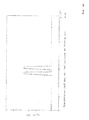
- a failure of pulses can be used as an additional comparison criterion, wherein the pulse interval is chosen so large that no interference occurs in the resource (see. Fig. 3 ).
- a counter-simulation with a mint, comparable (reference) resource can be used as a comparison criterion.
- the simulation basis forms an equivalent circuit diagram for frequency-dependent, spatially extended electrical equipment, discretized in n (single) elements.
- the voltage distribution at the input is split (cf. Fig. 9 ) in two components: one is the voltage curve without its reflections and the other is only the voltage curve with the reflections within the equipment. This results in a voltage curve Ue (t) and a voltage curve Ur (t).
- the loss energy in the case of missing interference in the resource is calculated once and for each interference point (constructive or destructive interference).
- Fig. 8 shows a diagram in which the dielectric energy losses over the portion of a subject to be examined, in particular a cable for energy transfer, are removed in%.
- the resource has a defective region with significantly degraded dielectric properties.
- the dielectric energy loss (referred size) is used both constructively and in the case of destructive interference of the pulses.
- Fig. 9 shows a schematic representation of an apparatus for performing the spatially resolved diagnostic method according to the invention on an extended resource, in particular a cable for electrical transmission of high electrical energy.
- the device 10 comprises inter alia a pulse or a signal generator 12, a filter system 14 for limiting the band of the input signal as well as a variable impedance 16 for adaptation to different types of operating means 26 or cables are connected downstream.
- a pulse or the signal generator 12 two similar, for example, rectangular pulses 18, 20 are generated with a variable pulse interval .DELTA.t and fed via the filter system 14 and the impedance 16 via a coupling line 22 in a beginning 24 of a device to be diagnosed 26 by way of example .
- the pulses 18, 20 can have an arbitrary voltage or current profile over the time t.
- two pulses 18, 20 are also referred to as a pulse pair in the context of this description.
- the spatially extended operating means 26, which is preferably a multicore high-voltage cable with 3 phases, but at least one core for electrical energy transmission or the like, here comprises by way of example a plurality of 1... N areas or cable segments or cable sections and has one Total length l on.
- an impedance Z is provided, which may be designed as an open end, as a short circuit or as an active termination.
- a preferably virtual, digitally simulated or a real replica 30 of the operating means 26, as indicated by a dotted line may be connected to the coupling line 22.
- a junction 32 in which it is z. B.
- a coupling element and / or a coupler is connected via a (measuring) line 34, a measuring device 36, in particular an analog-to-digital converter with a high sampling rate, with a fast, preferably a digital processing unit 38, such as z.
- a PC a digital oscilloscope, an analyzer, a logic array.
- the digital values of the analog voltages on the measuring line 34 output by the analog-digital converter arrive via data lines 39 (bus) to the arithmetic unit 38 for evaluation.
- the measuring device 36 forms here together with the arithmetic unit 38 an evaluation unit 40.
- the evaluation unit 40 may further not shown input and output devices, such. As screens, projectors, keyboards, sounders, printers, etc. include.
- the triggering or the triggering of the pulse generator preferably takes place on the basis of the results of the signal processing within the arithmetic unit 38.
- the pulse width tW or the temporal length of the pulses 18, 20 is likewise variable, wherein this is preferably the same in each case.
- the evaluation unit 40 By means of the evaluation unit 40, the voltage profile at the beginning 24 of the device 26 designed in the manner of a cable can be measured and evaluated.
- the pulse interval ⁇ t is preferably varied as a function of the results of the evaluation, so that all segments 1... N of the equipment 26 can be subjected to a high-precision, spatially resolved dielectric diagnosis. As a result, if necessary. Defective areas 1 ... N are reliably detected and, under certain circumstances, their remaining service life can be predicted so that an immediate replacement of the affected cable segment can be planned.
- the pulses may also be fed to the start 24 and / or end 28 of the resource 26.
- the pulses 18, 20 one of the in Fig. 9 merely exemplarily shown rectangular shape have a different course and z. B. have a triangular, a sawtooth, a trapezoidal, a sinusoidal, an exponential, a bell-shaped (ie Gaussian) course or a combination of at least two of said geometries.
- the Fig. 10 shows the within the (measuring) device of the invention Fig. 9 occurring voltage waveform UA (t) at the beginning 24 of the device 26, which is a superposition of Fig. 11 with the voltage curve UA (t) at the beginning 24 of the device 26 without reflections and of Fig. 12 with the exclusively the reflections containing voltage waveform UA (t) at the beginning 24 of the operating means 26 represents.
- the invention opens up the possibility for the first time of evaluating the state of individual segments or sections of a device to be examined, in particular of a high-voltage cable for electrical energy transmission, and of selectively exchanging them in the event of a fault or predicting their failure.
- z For energy utilities, for example, completely new possibilities in preventive cable diagnostics and asset management.
- Appropriate condition-based and risk-based strategies result in considerable potential savings in the maintenance and servicing of cable routes.
- With the help of the method according to the invention can also heterogeneous cable routes, such.
- the electrical state diagnosis is possible as a function of the location x along the longitudinal extent of the equipment (see g., Spatial resolution). As a result, individual cable segments or cable sections can be evaluated to the nearest meter in terms of their dielectric properties.
- the device also allows, inter alia, a measurement at the end of the equipment, so that no synchronization between the beginning and the end of the equipment is necessary. Rather, only a synchronization between the pulse or the signal generator and the measurement signal acquisition is needed.
- the hardware for signal generation, measurement and control has a compact design and, in contrast to conventional measuring methods and measurement setups, enables problem-free field use in the field, which is a clear advantage represents the state of the art.
Abstract
Das Verfahren und die Vorrichtung dienen zur ortsaufgelösten Diagnose des elektrischen Zustands eines räumlich ausgedehnten Betriebsmittels, insbesondere eines Kabels zur Übertragung elektrischer Energie, mit Hilfe von Interferenz zwischen in das Betriebsmittel durch einen Signalgenerator eingespeisten Impulsen. Hierbei sind grundsätzlich folgende Verfahrensschritte vorgesehen: a) Einspeisen von mindestens zwei um einen Impulsabstand t versetzten Impulsen in das Betriebsmittel, b) Erfassen der interferierten Impulse und Echos mittels einer Auswerteeinheit, c) Variation des Impulsabstandes t zur ortsaufgelösten Abtastung des Betriebsmittel entlang dessen Länge 1, d) Wiederholen der Schritte a) bis c) bis das Betriebsmittel zumindest abschittsweise abgetastet ist, und e) Auswerten der erfassten interferieren Impulse in der Auswerteeinheit. Für eine Vorrichtung zur Durchführung des Verfahrens ist dabei vorgesehen, dass mindestens ein Signalgenerator zur Erzeugung der Impulse mit dem Betriebsmittel und mit einer Auswerteeinheit verbunden ist, wobei zur ortsaufgelösten Diagnose lokale Energieverluste eW(x) über die Länge 1 des Betriebsmittels hinweg anhand einer Vielzahl von durch die Impulse hervorgerufenen Interferenzspannungsverläufen und rechnerisch ermittelbar sind.The method and the device serve for the spatially resolved diagnosis of the electrical state of a spatially extended piece of equipment, in particular a cable for the transmission of electrical energy, with the aid of interference between pulses fed into the piece of equipment by a signal generator. In principle, the following procedural steps are provided for this: a) feeding at least two pulses offset by a pulse spacing t into the equipment, b) detecting the interfered pulses and echoes by means of an evaluation unit, c) Variation of the pulse spacing t for spatially resolved scanning of the equipment along its length 1, d) repeating steps a) to c) until the resource is scanned at least in sections, and e) Evaluation of the detected interfering pulses in the evaluation unit. For a device for carrying out the method, it is provided that at least one signal generator for generating the pulses is connected to the equipment and to an evaluation unit, with local energy losses eW(x) over the length 1 of the equipment using a large number of interference voltage curves caused by the pulses and can be determined by calculation.
Description
Die Erfindung betrifft zunächst ein verfahren zur ortsaufgelösten Diagnose des elektrischen Zustands eines räumlich ausgedehnten Betriebsmittels, insbesondere eines Kabels zur Übertragung elektrischer Energie, mit Hilfe von Interferenz zwischen in das Betriebsmittel durch einen Signalgenerator eingespeisten Impulsen.The invention firstly relates to a method for the spatially resolved diagnosis of the electrical state of a spatially extended operating means, in particular of a cable for transmitting electrical energy, by means of interference between pulses fed into the operating means by a signal generator.
Darüber hinaus hat die Erfindung eine Vorrichtung zur ortsaufgelösten Diagnose eines elektrischen Zustands eines räumlich ausgedehnten Betriebsmittels, insbesondere eines Kabels zur Übertragung elektrischer Energie, mit Hilfe von Interferenz zwischen mindestens zwei um einen Impulsabstand Δt zeitlich versetzt in das Betriebsmittel eingespeisten Impulsen.In addition, the invention has a device for the spatially resolved diagnosis of an electrical condition of a spatially extended operating means, in particular a cable for transmitting electrical energy, by means of interference between at least two by a pulse interval .DELTA.t staggered pulses fed into the resource.
Der aktuelle Stand der Technik im Bereich der Zustandsdiagnose von Energieversorgungskabeln beruht auf hergebrachten Verfahren, wie z. B. der Messung von Teilentladungen sowie einer Bestimmung des Verlustfaktors (s. g. tan(δ)-Messung).The current state of the art in the field of condition diagnosis of power supply cables is based on traditional methods, such. B. the measurement of partial discharges and a determination of the loss factor (sg tan (δ) measurement).
Darüber hinaus sind weitere Verfahren, wie z. B. das Relaxationsstrommessverfahren sowie das Rückkehrspannungsmessverfahren bekannt. Bei diesen Messverfahren wird das zu untersuchende Kabel zunächst mit einer Gleichspannung polarisiert. Anschließend wird der Depolarisationsstrom bzw. die Rückkehrspannung nach einem Kurzschluss bestimmt. Mit diesen Messgrößen lässt sich wie im Fall der Verlustfaktorbestimmung der Zustand des Dielektrikums, wie z. B. der Feuchtegrad, der Isolationswiderstand etc., beurteilen. Es handelt sich jedoch um eine integrale Messmethode, die keine ortsaufgelöste Diagnose des Kabelzustands gestattet. Darüber hinaus sind diese Verfahren sehr empfindlich und störanfällig gegenüber äußeren Umgebungseinflüssen, wie z. B. Feuchtigkeit und Temperatur, sodass diese im Energieversorgungsbereich bislang nicht verbreitet wurde.In addition, other methods, such. B. the Relaxationsstrommessverfahren and the return voltage measurement method known. In these measuring methods, the cable to be examined is first polarized with a DC voltage. Subsequently, the depolarization current or the return voltage is determined after a short circuit. With these parameters, as in the case of loss factor determination, the state of the dielectric, such. B. the degree of moisture, the insulation resistance, etc., judge. However, it is an integral measuring method that does not allow a spatially resolved diagnosis of cable condition. In addition, these methods are very sensitive and susceptible to external environmental influences, such. As moisture and temperature, so that in the energy supply area has not been disseminated.
Bei der eingangs erwähnten Teilentladungsdiagnose (sogenannte "TE"-Diagnose (= Teilentladungs-Diagnose) werden Teilentladungsfehlstellen erkannt, bewertet und lokalisiert. Allein auf der Basis einer Teilentladungsdiagnose kann jedoch keine hinreichend verlässliche Aussage über den Kabelzustand bzw. dessen Restlebensdauer getroffen werden. Diese wird nur durch eine Kombination mit anderen Verfahren, wie z. B. der eingangs angesprochenen Verlustfaktormessung, möglich. Darüber hinaus ist es erforderlich, dass die Spannungsbelastung während der Messung größer ist als die Nennspannung, um überhaupt eine zuverlässige Zustandsprognose des Kabels zu erhalten. Aufgrund der hohen Spannungsbelastung kann jedoch eine zusätzliche Alterung bzw. Schädigung des zu diagnostizierenden Kabels hervorgerufen werden. Eine räumliche Lokalisierung einer Hauptentladungsstelle ist möglich, aber durch mehrfache Fehlstellen, hohe Kabellängen mit entsprechend starker Dämpfung oder Feuchtigkeit im Kabel, wird eine Lokalisierung deutlich erschwert.In the partial discharge diagnosis mentioned at the beginning (so-called "TE" diagnosis (partial discharge diagnosis) partial discharge defects are recognized, evaluated and localized.) However, based on a partial discharge diagnosis, it is not possible to make a sufficiently reliable statement about the cable state or its remaining service life Only in combination with other methods, such as the loss factor measurement mentioned above, it is also possible that the voltage load during the measurement is greater than the nominal voltage in order to obtain a reliable state prognosis of the cable at all However, high voltage stress can cause additional aging or damage to the cable to be diagnosed A spatial localization of a main discharge point is possible, but by multiple defects, high cable lengths with correspondingly high attenuation or moisture in the K Abel, a localization is much more difficult.
Aus der
Die Messung erfolgt unter Verwendung von Hochspannung, die an das Kabel angelegt wird. Anschließend werden Messspannungen mittels einer Spannungserfassungseinrichtung und einzelnen Messobjekten zuzuordnenden Strömen mittels der wenigstens zwei Stromerfassungseinrichtungen gemessen und in einer Auswerteeinheit ausgewertet.The measurement is made using high voltage applied to the cable. Subsequently, measuring voltages are measured by means of a voltage detection device and individual currents to be assigned to the measuring objects by means of the at least two current detection devices and evaluated in an evaluation unit.
Die Erzeugung der notwendigen Messhochspannung kann z. B. mit einem großen Transformator erfolgen, was jedoch aufwändig und teuer ist. Alternativ kann die Messhochspannung über ein Resonanzsystem oder ein s. g. "VLF"-Verfahren (= Very Low Frequency-Verfahren) erfolgen, die aber nicht mit der üblichen Netzfrequenz von 50 Hz arbeiten. Darüber hinaus handelt es sich um eine integrale Messmethode, d. h. eine Ortsauflösung ist nicht möglich und es kann mithin nur der Gesamtzustand eines Kabels beurteilt werden.The generation of the necessary Meßhochspannung z. B. done with a large transformer, which is complicated and expensive. Alternatively, the measuring high voltage via a resonance system or a s. G. "VLF" method (= Very Low Frequency method) are made, but do not work with the usual power frequency of 50 Hz. Moreover, it is an integral measuring method, i. H. a spatial resolution is not possible and therefore only the overall condition of a cable can be assessed.
Aus der
Hierbei wird die Frequenzbereichs-Reflektometrie ("FDR-Verfahren" = Frequency Domain Reflectometry-Verfahren) genutzt, die teilweise auch zur Zustandsdiagnose herangezogen werden kann. Ein Vorteil dieser Messmethode liegt darin, dass sie zerstörungs- sowie nahezu belastungsfrei durchführbar ist und demzufolge nur einen vergleichsweise geringen apparativen Aufwand erfordert.In this case, frequency domain reflectometry ("FDR method" = Frequency Domain Reflectometry method) is used, which can also be used partly for condition diagnosis. An advantage of this measurement method is that it is destructive and almost stress-free feasible and therefore requires only a relatively small amount of equipment.
Verfahrensgemäß wird eine Resonanzstellen- bzw. Frequenzspektral-Analyse durchgeführt, wobei als Eingangssignal meist ein Frequenzdurchlauf verwendet wird. Es lassen sich somit Impedanz-Änderungen entlang eines Kabels ähnlich wie bei der Zeitbereichs-Reflektometrie ("TDR" = Time Domain Reflectometry) ermitteln.According to the method, a resonance point or frequency spectral analysis is carried out, wherein a frequency sweep is usually used as the input signal. It is thus possible to determine impedance changes along a cable similar to time domain reflectometry ("TDR" = Time Domain Reflectometry).
Allerdings sind nur starke Änderungen der elektrischen Eigenschaften des Kabels detektierbar, wodurch sich der elektrische Zustand des Kabels bzw. des Dielektrikums nicht hinreichend aussagekräftig beurteilen lässt. Durch eine Vorpolarisierung des Prüflings durch eine hohe Gleichspannung können Fehlstellen unter Umständen besser hervorgehoben und durch eine anschließend durchgeführte TDR-Messung oder FDR-Messung überhaupt erst erkannt werden.However, only strong changes in the electrical properties of the cable can be detected, as a result of which the electrical condition of the cable or of the dielectric can not be assessed with sufficient meaning. Prepolarization of the device under test by a high DC voltage may under certain circumstances highlight flaws better and be recognized by a subsequently performed TDR measurement or FDR measurement.
Aus der
Hierbei handelt es sich im Prinzip um ein FDR-Messverfahren mit einer Resonanzstellen-Analyse. Diese Frequenzspektral-Analyse liefert jedoch kaum zuverlässige Informationen über den Zustand des Kabels, sofern keine (Referenz-)Messungen an einem identischen, intakten Kabel vorliegen.This is in principle an FDR measurement method with a resonance point analysis. However, this frequency spectral analysis provides little reliable information about the condition of the cable unless there are (reference) measurements on an identical, intact cable.
Aus der
Hierbei kommt das s. g. JTFDR-Messverfahren (JTFDR = "Joint Time Frequency Domain Reflectometry") zum Einsatz, das eine Kombination aus dem TDR-Messverfahren und dem FDR-Messverfahren darstellt. Hierbei wird ein angepasstes Eingangssignal in der Form eines Frequenzdurchlaufs mit einem Gauß-Impuls als Hüllkurve in das zu untersuchende Kabel eingespeist und die Eigenschaften von beiden Verfahren vereint.Here comes the s. G. JTFDR measurement technique (JTFDR = Joint Time Frequency Domain Reflectometry), which is a combination of the TDR measurement method and the FDR measurement method. In this case, an adapted input signal in the form of a frequency sweep with a Gaussian pulse as an envelope is fed into the cable to be examined and combines the properties of both methods.
Ein Nachteil dieses vorbekannten Verfahrens ist darin zu sehen, dass wiederum nur Änderungen der Impedanz bzw. des Frequenzspektrums detektierbar und auswertbar sind.A disadvantage of this previously known method is the fact that in turn only changes in the impedance or the frequency spectrum are detectable and evaluable.
Die
Hierbei wird das zu untersuchende Kabel am Anfang und am Ende in geeigneter Weise beschaltet, was z. B. durch eine variable Spannung, einen Innenwiderstand, eine variable Frequenz, eine Lastimpedanz oder dergleichen erfolgen kann, und so eine stehende Welle erzeugt. Mit Hilfe der Spannungs- und Stromverteilungen und einer Messung der Scheinleistung am Ein- und Ausgang des Kabels können Bilanzgleichungen aufgestellt werden, die durch N-malige Variation der Eingangsparameter ein Gleichungssystem ergeben, durch das sämtliche Leitungsparameter an einem beliebigen Punkt des Kabels theoretisch bestimmbar werden.Here, the cable to be examined at the beginning and at the end connected in a suitable manner, which z. B. by a variable voltage, an internal resistance, a variable frequency, a load impedance or the like can be done, and so generates a standing wave. With the aid of the voltage and current distributions and a measurement of the apparent power at the input and output of the cable, balance equations can be established which, by varying the input parameters N times, produce a system of equations which theoretically determines all line parameters at any point of the cable.
Dieses Verfahren impliziert jedoch einen immens hohen Messaufwand an beiden Seiten des zu untersuchenden Kabels, da eine Vielzahl von Messungen mit verschiedensten Eingangsparametern durchgeführt werden müssen, um ein Ergebnis zu erhalten.However, this method involves an immense amount of measurement on both sides of the cable to be examined, since a large number of measurements with a wide variety of input parameters must be carried out in order to obtain a result.
Eine Aufgabe der Erfindung ist es daher, ein Verfahren zur ortsaufgelösten elektrischen Diagnose eines räumlich ausgedehnten Betriebsmittels, insbesondere eines Hochspannungskabels zur Energieübertragung anzugeben. Darüber hinaus ist eine Aufgabe der Erfindung eine mobile und zugleich einfach zu handhabende Vorrichtung zur Durchführung des Verfahrens anzugeben.An object of the invention is therefore to provide a method for spatially resolved electrical diagnosis of a spatially extended equipment, in particular a high-voltage cable for energy transmission. In addition, an object of the invention is to provide a mobile and at the same time easy-to-use device for carrying out the method.
Diese Aufgabe wird zunächst durch ein Verfahren nach Maßgabe des Patentanspruchs 1 mit den folgenden Schritten gelöst:
- a) Einspeisen von mindestens zwei um einem Impulsabstand Δt versetzten Impulsen in das Betriebsmittel,
- b) Erfassen der interferierten Impulse und Echos mittels einer Auswerteeinheit,
- c) Variation des Impulsabstandes Δt zur ortsaufgelösten Abtastung des Betriebsmittels entlang dessen
Länge 1, - d) Wiederholen der Schritte a) bis c) bis das Betriebsmittel zumindest abschnittsweise abgetastet ist, und
- e) Auswerten der erfassten interferierten Impulse in der Auswerteeinheit.
- a) feeding at least two pulses offset by a pulse interval Δt into the operating medium,
- b) detecting the interfered pulses and echoes by means of an evaluation unit,
- c) variation of the pulse spacing Δt for spatially resolved sampling of the device along its
length 1, - d) repeating steps a) to c) until the equipment is scanned at least in sections, and
- e) evaluating the detected interfered pulses in the evaluation unit.
Hierdurch ist eine präzise, ortsaufgelöste Diagnose deselektrischen Zustands eines räumlich vorrangig in seiner Längsrichtung ausgedehnten Betriebsmittels, insbesondere eines Kabels zur Energieversorgung, einschließlich etwaiger Kopplungselemente, wie z. B. Kabelmuffen, möglich. Das Verfahren ermöglicht hinreichend belastbare Aussagen über lokale qualitative Eigenschaften, so dass mit zusätzlichem Expertenwissen die Ausfallwahrscheinlichkeit exakt definierter Kabelsegmente bzw. Kabelabschnitte prognostiziert werden kann. Aufgrund des vergleichsweise geringen Messaufwands kann das Verfahren auch für Kabelmessungen im Feld, d. h. vor Ort, eingesetzt werden. Die Form der Impulse kann grundsätzlich einen beliebigen zeitlichen Verlauf aufweisen.This is a precise, spatially resolved diagnosis of the electrical condition of a spatially primarily extended in its longitudinal direction operating means, in particular a cable for power supply, including any coupling elements, such. B. cable sleeves, possible. The method allows sufficiently reliable statements about local qualitative properties, so that the probability of failure of precisely defined cable segments or cable sections can be predicted with additional expert knowledge. Due to the comparatively low measurement effort, the method can also be used for cable measurements in the field, i. H. be used on site. The form of the pulses can basically have an arbitrary temporal course.
Im Fall einer günstigen Ausgestaltung werden im Verfahrensschritt e) zur ortsaufgelösten Diagnose lokale Energieverluste eW(x) über die Länge l des Kabels hinweg anhand einer Vielzahl von durch die Impulse hervorgerufenen Interferenzspannungsverläufen und Spannungsverläufen rechnerisch ermittelt, wobei die Spannungsverläufe mittels der Auswerteeinheit digitalisiert und rechnerisch zu einer fehlerfreien Nachbildung des Betriebsmittels in Beziehung gesetzt werden.In the case of a favorable embodiment, local energy losses eW (x) over the length l of the cable are determined mathematically in method step e) for spatially resolved diagnosis using a plurality of interference voltage profiles and voltage profiles produced by the pulses, wherein the voltage profiles are digitized by means of the evaluation unit and calculated an error-free simulation of the equipment.
Hierdurch lassen sich verlässliche, ortsaufgelöste Aussagen über den elektrischen Zustand des Betriebsmittels treffen. Zusätzlich können interferenzfreie Spannungsverläufe zu den Interferenzspannungsverläufen in Beziehung gesetzt werden, um die Auswertung zu optimieren. Infolge der digitalen Auswerteeinheit ist eine Erfassung und rechnerische Auswertung der vom Analog-Digitalwandler aufgenommenen Spannungsverläufe in Echtzeit möglich.This makes it possible to make reliable, spatially resolved statements about the electrical state of the equipment. In addition, interference-free voltage waveforms can be related to the interference voltage waveforms to optimize the evaluation. As a result of the digital evaluation unit, a recording and computational evaluation of the recorded voltage waveforms from the analog-to-digital converter in real time is possible.
Bei einer weiteren vorteilhaften Ausgestaltung des Verfahrens interferieren jeweils zwei Impulse gleicher oder gegensätzlicher Polarität konstruktiv oder destruktiv miteinander.In a further advantageous embodiment of the method, in each case two pulses of the same or opposite polarity interfere constructively or destructively with one another.
Hierdurch kann im Rahmen des erfindungsgemäßen Messverfahrens sowohl die konstruktive Interferenz zwischen den in das Kabel eingespeisten Impulspaaren und/oder auch deren destruktive Interferenz ausgenutzt werden.As a result, in the context of the measuring method according to the invention, both the constructive interference between the pulse pairs fed into the cable and / or their destructive interference can be exploited.
Nach Maßgabe einer günstigen Weiterentwicklung werden Impulse und Impulsfolgen mit einer Maximalamplitude von bis zu 1.000 Volt erzeugt.According to a favorable further development pulses and pulse trains are generated with a maximum amplitude of up to 1,000 volts.
Hierdurch ist eine schonende Prüfung des Betriebsmittels ohne die Gefahr einer Vergrößerung bereits etwaig bestehender dielektrischer Vorschäden möglich. Die eingesetzten Impulse können z. B. eine rechteckförmige, trapezförmige, dreieckförmige, sägezahnförmige, sinusförmige, sin(x)/x-förmige, exponentielle, halbkreisförmige, halbelliptische, gefenstert rechteckförmige, glockenförmige (Gauß-förmige) Impulsform oder eine beliebige Kombination von mindestens zwei der genannten Impulsformen aufweisen. Die gefensterten Rechteckimpulse können z. B. nach Art von "Hamming", "Blackmann", "Harris", "Kaiser" oder "von Hann" ausgebildet sein.As a result, a careful examination of the equipment is possible without the risk of increasing already existing existing existing dielectric damage. The pulses used can, for. B. have a rectangular, trapezoidal, triangular, sawtooth, sinusoidal, sin (x) / x-shaped, exponential, semi-circular, semi-elliptic, geffenstert rectangular, bell-shaped (Gaussian) pulse shape or any combination of at least two of said pulse shapes. The fenestrated rectangular pulses can, for. B. in the manner of "Hamming", "Blackman", "Harris", "Kaiser" or "trained by Hann".
Durch eine geeignete Wahl der Impulsform (z. B. Gauß-Impuls etc.) der in das Betriebsmittel eingespeisten Impulse werden die Diagnosemöglichkeiten des erfindungsgemäßen Messverfahrens optimiert. Durch die geeignete Wahl der Impulsform kann ferner eine Dispersionskorrektur erfolgen. Zu diesem Zweck kann man z. B. Impulse erzeugen, die in einem interessierenden, insbesondere zu untersuchenden Abschnitt des ausgedehnten Betriebsmittels bzw. des Kabels rechteckförmig sind, aber an dessen Anfang gerade nicht.By a suitable choice of the pulse shape (eg Gaussian pulse, etc.) of the pulses fed into the operating means, the diagnostic possibilities of the measuring method according to the invention are optimized. By suitable choice of the pulse shape, a dispersion correction can also be carried out. For this purpose you can z. B. generate pulses that are rectangular in an interesting, in particular to be examined portion of the extended resource or the cable, but not at the beginning of it.
Nach Maßgabe einer weiteren günstigen Ausgestaltung wird die Länge 1 des Betriebsmittels mittels der digitalen Auswerteeinheit und des Signalgenerators, insbesondere mit Hilfe einer Laufzeitmessung mindestens eines Impulses, erfasst.According to a further advantageous embodiment, the
Hierdurch ist eine einfache Bestimmung der Länge l des zu diagnostizierenden Betriebsmittels möglich. Die Kenntnis der genauen Länge l ist unter anderem notwendig, um den Impulsabstand Δt der in das Kabel eingespeisten Impulse so zu beeinflussen, dass diese an einer zu untersuchenden Stelle x miteinander interferieren bzw. überhaupt eine Interferenz erfolgt. Durch die sukzessive Variation des Impulsabstandes Δt der in das Kabel eingespeisten Impulspaare kann das Kabel über seine Gesamtlänge l präzise abgetastet und elektrisch evaluiert werden. Alternativ kann die Ermittlung der Gesamtlänge des Betriebsmittels auch mittels bekannter TDR-Verfahren, FDR-Verfahren oder einer Kombination hiervon erfolgen.As a result, a simple determination of the length l of the device to be diagnosed is possible. The knowledge of precise length l is necessary, inter alia, in order to influence the pulse spacing .DELTA.t of the pulses fed into the cable in such a way that they interfere with each other at a point x to be examined or that interference occurs at all. Due to the successive variation of the pulse interval Δt of the pulse pairs fed into the cable, the cable can be precisely scanned over its entire length l and electrically evaluated. Alternatively, the determination of the total length of the equipment can also be carried out by means of known TDR methods, FDR methods or a combination thereof.
Bei einer weiteren günstigen Fortbildung des Verfahrens ist vorgesehen, dass die ortsaufgelöste Diagnose des elektrischen Zustands des Kabels vollautomatisch unter bevorzugter Kontrolle der digitalen Auswerteeinheit und/oder manuell erfolgt.In a further favorable development of the method, it is provided that the spatially resolved diagnosis of the electrical state of the cable takes place fully automatically under preferred control of the digital evaluation unit and / or manually.
Hierdurch ist ein problemloser und weitgehend von Messfehlern freier Einsatz des erfindungsgemäßen Messverfahrens zur Kabeldiagnose gegeben. Ergänzend oder alternativ ist eine manuelle Ablaufsteuerung des Verfahrens möglich.As a result, a problem-free and largely free from measurement errors use of the measuring method according to the invention for cable diagnosis is given. Additionally or alternatively, a manual process control of the method is possible.
Darüber hinaus wird die erfindungsgemäße Aufgabe durch eine Vorrichtung nach Maßgabe von Patentanspruch 7 gelöst.In addition, the object of the invention is achieved by a device according to claim 7.
Dadurch, dass mindestens ein Signalgenerator zur Erzeugung der Impulse mit dem Betriebsmittel und mit einer Auswerteeinheit verbunden ist, wobei zur ortsaufgelöste Diagnose lokale Energieverluste eW(x) über die Länge 1 des Betriebsmittels hinweg anhand einer Vielzahl von durch die Impulse hervorgerufenen Interferenzspannungsverläufen und Spannungsverläufen rechnerisch ermittelbar sind, ist eine genaue, ortsaufgelöste Diagnose des elektrischen Zustands eines ausgedehnten Betriebsmittels, insbesondere dessen Dielektrikums, über seine Gesamtlänge l hinweg mit einem vergleichsweise geringen Messaufwand möglich. Dies gestattet verlässliche Aussagen über den elektrischen Zustand von einzelnen Abschnitten des primär in seiner Längsrichtung ausgedehnten Betriebsmittels unter Einbeziehung von etwaig vorhandenen Verbindungselementen, wie zum Beispiel Kabelmuffen oder dergleichen.Characterized in that at least one signal generator for generating the pulses to the resource and an evaluation unit is connected, wherein for spatially resolved diagnosis local energy losses eW (x) across the length of the
Durch die geeignete Wahl der Impulsform (z. B. Gauß-Impuls) der mittels des Signal- bzw. des Impulsgenerators erzeugten und in das Betriebsmittel eingespeisten Impulse werden die Diagnosemöglichkeiten des erfindungsgemäßen Messverfahrens erheblich erweitert. Die Form der Impulse kann hierbei einen beliebigen zeitlichen Verlauf aufweisen und z. B. rechteckförmig, trapezförmig, dreieckförmig, sinusförmig, glockenförmig (Gauß-förmig) oder mit einer Überlagerung derartiger Geometrien gebildet sein. Ergänzend oder alternativ können die Impulse auch durch das abschnittsweise Zusammensetzen unterschiedlicher Geometrien gebildet sein. Die Impulse können z. B. in Bezug zu ihrer Mitte (tW/2) asymmetrisch sein. Durch die Pulsform erfolgt zudem die Dispersionskorrektur. Zu diesem Zweck erzeugt der Signalgenerator Impulse, die in einem interessierenden, insbesondere in dem zu untersuchenden Abschnitt des ausgedehnten Betriebsmittels bzw. des Kabels rechteckförmig sind, aber an dessen Anfang eine hiervon abweichende Verlaufsform aufweisen. Das geht nur eingeschränkt, weil die sich überlagernden Pulse unterschiedliche Lauflängen haben.By suitable choice of the pulse shape (eg Gaussian pulse) of the pulses generated by means of the signal generator or of the pulse generator and fed into the operating means, the diagnostic possibilities of the measuring method according to the invention are considerably expanded. The shape of the pulses can in this case have an arbitrary time course and z. B. rectangular, trapezoidal, triangular, sinusoidal, bell-shaped (Gaussian) or be formed with an overlay of such geometries. Additionally or alternatively, the pulses can also be formed by the piecemeal assembly of different geometries. The pulses can z. B. with respect to their center (tW / 2) be asymmetric. The pulse shape also causes the dispersion correction. For this purpose, the signal generator generates pulses which are rectangular in a section of the extended equipment or cable of interest, in particular in the section to be examined, but at the beginning of which have a different shape. This is only limited because the overlapping pulses have different run lengths.
Nach Maßgabe einer günstigen Ausgestaltung sind die Spannungsverläufe mittels der Auswerteeinheit digitalisierbar und rechnerisch zu einer fehlerfreien Nachbildung des Betriebsmittels in Beziehung setzbar.In accordance with a favorable embodiment, the voltage profiles can be digitized by means of the evaluation unit and computationally put into relation to an error-free simulation of the equipment.
Hierdurch lassen sich fehlerhafte Abschnitte des Betriebsmittels zuverlässig und in der Regel rechtzeitig vor einem elektrischen Totalversagen erkennen.As a result, faulty sections of the equipment can be reliably and usually detect timely before a total electrical failure.
Bei einer vorteilhaften Weiterbildung sind dem Signalgenerator ein Filtersystem und eine variable Impedanz nachgeschaltet, wobei die anpassbare Impedanz mit einem Anfang des Betriebsmittels verbunden ist.In an advantageous development, the signal generator is followed by a filter system and a variable impedance, wherein the adjustable impedance with a beginning of the resource connected is.
Hierdurch ist eine messtechnisch optimale Ankopplung an das Betriebsmittel bzw. das Energiekabel gegeben.As a result, a metrologically optimal coupling to the equipment or the power cable is given.
Gemäß einer Ausgestaltung ist der Auswerteeinheit eine Messeinrichtung, insbesondere ein Analog-Digitalwandler, und mindestens eine digitale Recheneinheit, zugeordnet.According to one embodiment, the evaluation unit is assigned a measuring device, in particular an analog-digital converter, and at least one digital computing unit.
Hierdurch können die Spannungsverläufe und ihre Echos mit hoher Genauigkeit in Echtzeit erfasst und ausgewertet werden. Vorzugsweise ist mindestens ein Bildschirm als eine optische Ausgabeeinheit vorgesehen. Ferner kann die Auswerteeinheit auch einen Drucker aufweisen. Darüber hinaus kann der Auswerteeinheit auch eine akustische Signaleinrichtung, wie z. B. ein Lautsprecher zur Ausgabe von Signaltönen und/oder von Pieptönen für bestimmte Betriebszustände oder Fehlermeldungen und/oder eine Sprachausgabe zugeordnet sein.As a result, the voltage waveforms and their echoes can be detected and evaluated with high accuracy in real time. Preferably, at least one screen is provided as an optical output unit. Furthermore, the evaluation unit can also have a printer. In addition, the evaluation unit and an acoustic signaling device, such. B. a speaker for the output of beeps and / or be assigned by beeps for certain operating conditions or error messages and / or a voice output.
Nach Maßgabe einer Ausgestaltung der Vorrichtung ist ein Ende des Betriebsmittels offen oder mit einer Impedanz Z abgeschlossen.According to an embodiment of the device, one end of the equipment is open or terminated with an impedance Z.
Hierdurch lässt sich die Interferenz der in das Betriebsmittel eingespeisten Impulse beeinflussen.In this way, the interference of the pulses fed into the operating medium can be influenced.
Weiterhin ist vorgesehen, dass die fehlerfreie Nachbildung des Betriebsmittels mit dem Signalgenerator und der Auswerteeinheit koppelbar ist.Furthermore, it is provided that the error-free simulation of the equipment with the signal generator and the evaluation unit can be coupled.
Hierdurch sind Referenzmessungen und Auswertungen mit einem identischen, jedoch zweifelsfrei intakten Betriebsmittel bzw. Kabel möglich, wobei die Nachbildung bevorzugt mittels einer digitalen Simulation innerhalb der Auswerteeinheit realisiert ist.As a result, reference measurements and evaluations with an identical but unambiguously intact equipment or cable are possible, the replica preferably being realized by means of a digital simulation within the evaluation unit.
Bei einer weiteren günstigen Fortbildung ist vorgesehen, dass mittels des Signalgenerators Impulse gleicher Polarität oder Impulse mit gegensätzlicher Polarität erzeugbar sind.In a further favorable development is provided that by means of the signal generator pulses of the same polarity or Pulses of opposite polarity can be generated.
Hierdurch können die in das Betriebsmittel eingespeisten Impulse im Wege konstruktiver oder destruktiver Interferenz miteinander wechselwirken.As a result, the pulses fed into the operating medium can interact with one another by means of constructive or destructive interference.
Gemäß einer vorteilhaften Ausgestaltung ist eine Länge 1 des Betriebsmittels mittels der Auswerteeinheit und des Signalgenerators, insbesondere mit Hilfe einer Laufzeitmessung mit mindestens einem Impuls erfassbar.According to an advantageous embodiment, a
Hierdurch ist eine besonders einfache Erfassung der Gesamtlänge 1 des zu diagnostizierenden Kabels bzw. Betriebsmittels, möglich.As a result, a particularly simple detection of the
In der Zeichnung zeigt:
- Fig. 1
- Energieverlust bei Interferenz der Impulspaare in einem veränderten Bereich eines vorrangig in seiner Längsrichtung ausgedehnten Betriebsmittels,
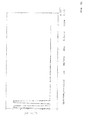
- Fig. 2
- Energieverlust bei Interferenz der Impulspaare in einem homogenen (intakten) Bereich des Betriebsmittels,
- Fig. 3
- Energieverlust bei fehlender Interferenz der Impulspaare in dem Betriebsmittel,
- Fig. 4
- Spannungsverlauf bei konstruktiver Interferenz der Impulspaare,
- Fig. 5
- Stromverlauf bei konstruktiver Interferenz der Impulspaare,
- Fig. 6
- Spannungsverlauf bei destruktiver Interferenz der Impulspaare,
- Fig. 7
- Stromverlauf bei destruktiver Interferenz der Im pulspaare,
- Fig. 8
- dielektrische Energieverluste bei konstruktiver und destruktiver Interferenz des Kabels mit einem defekten Bereich bei ca. 30 % einer (Gesamt-)
länge 1 des Betriebsmittels, - Fig. 9
- elektrisches Blockschaltbild einer Ausführungsform einer erfindungsgemäßen Vorrichtung zur Durchführung des Verfahrens,
- Fig. 10
- einen Spannungsverlauf UA(t) an einem Anfang des Betriebsmittels,
- Fig. 11
- den Spannungsverlauf UA(t) am Anfang des Betriebsmittels ohne Reflexionen, und
- Fig. 12
- den Spannungsverlauf UA(t) am Anfang des Betriebsmittels mit Reflexionen.
- Fig. 1
- Energy loss upon interference of the pulse pairs in a changed region of a device, which is primarily extended in its longitudinal direction,
- Fig. 2
- Energy loss on interference of the pulse pairs in a homogeneous (intact) area of the equipment,
- Fig. 3
- Energy loss in the absence of interference of the pulse pairs in the resource,
- Fig. 4
- Voltage curve with constructive interference of the pulse pairs,
- Fig. 5
- Current course with constructive interference of the pulse pairs,
- Fig. 6
- Voltage curve with destructive interference of the pulse pairs,
- Fig. 7
- Current course with destructive interference of the pulspaare,
- Fig. 8
- dielectric energy losses with constructive and destructive interference of the cable with a defective area at approx. 30% of a (total)
length 1 of the equipment, - Fig. 9
- electrical block diagram of an embodiment of a device according to the invention for carrying out the method,
- Fig. 10
- a voltage waveform UA (t) at a beginning of the resource,
- Fig. 11
- the voltage curve UA (t) at the beginning of the equipment without reflections, and
- Fig. 12
- the voltage curve UA (t) at the beginning of the resource with reflections.
Vorab sollen kurz die theoretischen Grundlagen des erfindungsgemäßen Verfahrens erläutert werden. Das Verfahren nutzt die Interferenzeigenschaften von elektrischen Wanderwellen aus, um eine ortsaufgelöste Diagnose von einem räumlich vorrangig in seiner Längsrichtung ausgedehnten Betriebsmittel, insbesondere einem Kabel zur Energieübertragung, zu ermöglichen und die Eigenschaften des Dielektrikums mit hoher Genauigkeit qualitativ zu beschreiben.In advance, the theoretical principles of the method according to the invention will be briefly explained. The method exploits the interference characteristics of traveling electrical waves in order to enable a spatially resolved diagnosis of a spatially primarily extended in his longitudinal resources, in particular a cable for energy transfer, and to describe the properties of the dielectric with high accuracy qualitatively.
Unter dem Terminus eines "räumlich in seiner Längsrichtung ausgedehnten Betriebsmittels" werden im Kontext dieser Beschreibung hauptsächlich ein- oder mehradrige Energieversorgungskabel aller Spannungsebenen, unter Einschluss etwaig notwendiger Kopplungs- und Anbindungselemente, wie z. B. Muffen und dergleichen, verstanden.In the context of this description, the term "equipment spatially extended in its longitudinal direction" primarily refers to single or multi-core power supply cables of all voltage levels, including any necessary coupling and connection elements, such as, for example, As sleeves and the like understood.
Im Zuge des erfindungsgemäßen Verfahrens wird eine Vielzahl von Wanderwellen bildenden Impulspaaren in das zu untersuchende Betriebsmittel bzw. das Kabel eingespeist. Die die Wanderwellen hervorrufenden Impulse breiten sich in dem zu untersuchenden Betriebsmittel mit einer endlichen Geschwindigkeit v aus und werden durch leitungsbedingte Verluste gedämpft und verzerrt.In the course of the method according to the invention, a multiplicity of traveling-wave-forming pulse pairs are fed into the equipment or cable to be examined. The pulses causing the traveling waves propagate in the equipment to be examined at a finite speed v and are attenuated and distorted by line-related losses.
Dieses Verhalten wird mit der komplexen Fortpflanzungskonstante γ berücksichtigt. Sie setzt sich aus einem reellen α und einem imaginären Anteil β zusammen. Der Realteil α der Fortpflanzungskonstante wird als Dämpfungskonstante und der Imaginärteil β als Phasenkonstante bezeichnet. ![]()
![]()
Geht man von einer hier zulässigen Vereinfachung für Wanderwellen aus, berechnet sich die Ausbreitungs- bzw. Fortpflanzungsgeschwindigkeit aus dem Induktivitäts- und dem Kapazitätsbelag des Mediums wie folgt: ![]()
![]()
Treten im Kabel Dämpfung und Dispersion auf, so unterscheidet man noch eine Gruppen- und Phasengeschwindigkeit, bei denen ein Widerstands- und ein Leitwertbelag berücksichtigt werden müssen. Eine Wanderwelle besteht in diesem Fall aus einem zeitdiskreten Signal, das als ein Impuls mit einer definierten Amplitude, Impulsbreite tW und -form interpretiert wird. Diese Größen sind variabel und abhängig vom zu diagnostizierenden Kabel. Gemessen wird der Spannungs- bzw. Stromverlauf am Eingang bzw. Ausgang des Kabels. Dieses Vorgehen ähnelt zunächst der Zeitbereichs-Reflektometrie bzw. Time-Domain-Reflectometry (TDR).If attenuation and dispersion occur in the cable, a distinction is made between a group and phase velocity, in which a resistance and conductance coating must be taken into account. A traveling wave in this case consists of a discrete-time signal, which is interpreted as a pulse with a defined amplitude, pulse width tW and -form. These sizes are variable and dependent on the cable to be diagnosed. The voltage or current profile at the input or output of the cable is measured. This procedure is initially similar to time domain reflectometry or time domain reflectometry (TDR).
Im Unterschied dazu wird beim erfindungsgemäßen Verfahren nicht ein einzelner Impuls oder Sprung erzeugt, sondern immer ein Impulspaar mit einem definierten Impulsabstand Δt. Diese Impulse werden von einer bzw. von beiden Seiten aus eingespeist. In beiden Fällen sollen sich die Impulspaare an einer konkreten Stelle x, die sich aus dem vorher definierten Impulsabstand ergibt, im Ausbreitungsmedium treffen. Hierbei gilt: 0 ≤ x ≤ l, wobei 1 die Gesamtlänge des zu untersuchenden des Betriebsmittels ist. Betrachtet man zunächst die einseitige Speisung, kann dies dadurch erreicht werden, dass am Leitungsanfang ein Impulspaar eingespeist wird und das Leitungsende "offen" ist. Somit ergibt sich am Ende eine Reflexion der Wanderwellen bzw. des Impulspaares - wobei der Reflexionsfaktor der Spannung am offenen Kabelende Eins ist - und es entsteht eine zurücklaufende Welle. Die zurücklaufende Wanderwelle bzw. der erste Impuls und die zweite noch nachlaufende Welle bzw. der zweite Impuls treffen sich in dem Betriebsmittel bzw. dem Kabel an der Stelle x, die abhängig ist vom Impulsabstand und der Ausbreitungsgeschwindigkeit. Eine weitere Variante ist die Terminierung des Kabels mit einer variablen Impedanz Zk+1, wodurch sich andere Reflexionsfaktoren ergeben. ![]()
![]()
Am Ende des Betriebsmittels, wenn Zk+l → ∞ gilt: ![]()
![]()
An der Stelle, an der sich die Impulse treffen bzw. überlagern, tritt Interferenz auf und es entstehen dort lokal erhöhte bzw. erniedrigte elektrische Verluste im Vergleich zu den restlichen Abschnitten innerhalb des Dielektrikums des zu untersuchenden Betriebsmittels. Dadurch wird eine wirkliche Ortsauflösung im Zuge des erfindungsgemäßen Verfahrens möglich. Der Wellenwiderstand des Betriebsmittels ergibt sich hierbei wie folgt: 
Vereinfachte Formel des Wellenwiderstands nach der Wellentheorie mit reellen Größen: 
Weiterhin gilt die allgemeine Formel des Energieverlustes: ![]()
![]()
Die Verlustleistung in einem diskreten Element (Abschnitt) des zu untersuchenden Betriebsmittels folgt der Beziehung: 
So entstehen an der Interferenzstelle x deutlich erhöhte elektrische Verluste, die direkt an der Stoßstelle maximal sind und zum Rand hin abnehmen. Vernachlässigt man die Dämpfung auf der Leitung, ergibt sich gemäß Gleichung (7) eine Verteilung der Verluste in Form eines Dreiecks, wie sie auch in den
In den
In dem Diagramm von
Betrachtet man weiterhin den idealen, ungedämpften Fall, lassen sich diese Energieverläufe mit den Spannungs- bzw. Stromverläufen am Eingang und an der Interferenzstelle im Kabel, wie in
Es kommt an dem Treffpunkt der beiden in das Betriebsmittel eingespeisten Impulse bzw. im Interferenzpunkt der Impulse - wie mit einer gestrichelten Linie angedeutet - zu einer Spannungsverdopplung bzw. zu einem vollständigen Auslöschen des Stromes. Diese Spannungsverdopplung wirkt an der Stoßstelle der Impulse am längsten ein und erzeugt somit dort auch die größten dielektrischen Verluste. Diese lokal erzeugten Verluste stellen die Diagnosegrundlage des erfindungsgemäßen Verfahrens dar. Daraus lassen sich an jeder zu untersuchenden Stelle x des Betriebsmittels die relevanten Kenngrößen des Dielektrikums präzise ermitteln und bewerten.It comes at the meeting point of the two pulses fed into the resources or in the interference point of the pulses - as indicated by a dashed line - to a voltage doubling or to a complete extinguishment of the current. This voltage doubling acts longest at the junction of the pulses and thus generates the largest dielectric losses there as well. These locally generated losses represent the diagnostic basis of the method according to the invention. From this, the relevant parameters of the dielectric can be precisely determined and evaluated at each point x of the equipment to be examined.
Um die dielektrischen Eigenschaften in Abhängigkeit des Ortes zu ermitteln, muss mit Hilfe des erfindungsgemäßen Verfahrens das zu untersuchende Medium über seine Gesamtlänge l hinweg abgetastet werden. Dies geschieht durch Veränderung des Impulsabstandes Δt der beiden eingespeisten Impulse bzw. des Impulspaares.In order to determine the dielectric properties as a function of the location, the medium to be examined must be scanned across its entire length l with the aid of the method according to the invention. This is done by changing the pulse interval .DELTA.t of the two pulses fed or the pulse pair.
Zunächst muss die Gesamtlaufzeit tTransit bzw. tDurchlauf der Impulse durch das Betriebsmittel, die jeweils abhängig von der Ausbreitungsgeschwindigkeit und Länge des Betriebsmittels ist, bestimmt werden. Dieses kann beispielsweise mit Hilfe einer Reflexionsmessung im zeitbereich oder im Frequenzbereich, d. h. mittels einer hergebrachten TDR-Messung bzw. FDR-Messung erfolgen. Unabhängig von dem angewendeten Messverfahren zur Bestimmung aller relevanten elektrischen Leitungsparameter ist der kleinste Impulsabstand ΔtMin stets abhängig von der Impulsbreite tW und muss hierbei immer größer oder gleich der Impulsbreite tW sein. Die Anzahl der zeitlich auflösbaren Schritte zwischen ΔtMin und ΔtMax ergibt die minimale Schrittweite (Auflösung) der Abtastung in axialer Richtung des Betriebsmittels. Durch die Impulsbreite tW ist ferner die reale Breite der Interferenzzone der beiden Impulse, die Ausbreitungsgeschwindigkeit sowie die Überlappungszeit der Impulse beeinflussbar.First, the total transit time tTransit or tPurchlauf of the pulses must be determined by the resource, which is dependent on the propagation speed and length of the resource, respectively. This can be done for example by means of a reflection measurement in the time domain or in the frequency domain, ie by means of a conventional TDR measurement or FDR measurement. Regardless of the measuring method used to determine all relevant electrical line parameters the smallest pulse interval ΔtMin is always dependent on the pulse width tW and must always be greater than or equal to the pulse width tW. The number of time-resolvable steps between ΔtMin and ΔtMax gives the minimum step size (resolution) of the scan in the axial direction of the resource. The pulse width tW further influences the real width of the interference zone of the two pulses, the propagation speed and the overlap time of the pulses.
Der Impulsabstand Δt bei Interferenz an einer zu untersuchenden Stelle x, bei einer Gesamtlänge 1 des Kabels und einer Ausbreitungsgeschwindigkeit v der Impulse, lässt sich allgemein wie folgt berechnen: ![]()
![]()
Somit ergibt sich der größtmögliche Impulsabstand ΔtMax wie folgt: ![]()
![]()
Als Ergebnis erhält man einen Ortsverlauf der lokal erzeugten elektrischen Verluste in Abhängigkeit der Messgrößen, was die Diagnosegrundlage für eine Bewertung der Einzelsegmente mittels des erfindungsgemäßen Verfahrens bildet. Für die Auswertung der Messergebnisse existiert eine Vielzahl von Möglichkeiten, wie z. B. die Bewertung des ortsabhängigen Zustands über den Energieverlust an der jeweiligen Stelle.As a result, one obtains a local course of the locally generated electrical losses as a function of the measured variables, which forms the basis of diagnosis for an evaluation of the individual segments by means of the method according to the invention. For the evaluation of the measurement results exists a variety of ways, such. B. the evaluation of the location-dependent state on the energy loss at the respective location.
Beispielsweise kann durch die Erzeugung von jeweils konstruktiver und destruktiver Interferenz an einer konkreten, zu untersuchenden Stelle x des zu diagnostizierenden Betriebsmittels die Genauigkeit der Auswertung der lokalen Kenngrößen bzw. der Kriterien durch geeignete Algorithmen erheblich erhöht werden, wobei zwei Optionen zur Auswahl stehen:For example, the generation of respectively constructive and destructive interference at a specific point to be examined x of the device to be diagnosed can considerably increase the accuracy of the evaluation of the local parameters or the criteria by suitable algorithms, two options being available:
Konstruktive Interferenz (vgl. insb.
Ferner kann eine Ermittlung und Lokalisierung von starken Impedanz-Änderungen und Reflexionsstellen in dem Betriebsmittel mit Hilfe angepasster TDR bzw. FDR (z. B. Gauß-Impuls-Reversal, Kreuzkorrelation, Resonanzstellen, Frequenzspektrum) erfolgen. Ein Nichttreffen von Impulsen kann als zusätzliches Vergleichskriterium herangezogen werden, wobei der Impulsabstand so groß gewählt wird, dass keine Interferenz in dem Betriebsmittel auftritt (vgl.
Darüber hinaus kann eine Gegensimulation mit einem neuwertigen, vergleichbaren (Referenz-)Betriebsmittel als ein Vergleichskriterium erfolgen. Die Simulationsgrundlage bildet ein Ersatzschaltbild für frequenzabhängige, räumlich ausgedehnte elektrische Betriebsmittel, diskretisiert in n (Einzel-)Elementen.In addition, a counter-simulation with a mint, comparable (reference) resource can be used as a comparison criterion. The simulation basis forms an equivalent circuit diagram for frequency-dependent, spatially extended electrical equipment, discretized in n (single) elements.
Ferner können im Rahmen einer weiter optimierten rechnerischen Auswertung eine Kombination verschiedener Kriterien, wie z. B. der Energieverlust für den Fall von konstruktiver, destruktiver Interferenz und/oder keiner Interferenz, sowie für ein homogenes bzw. inhomogenes, räumlich in seiner Längsrichtung ausgedehntes Betriebsmittel, weitergehende mathematische Kriterien und Korrelationen hieraus herangezogen werden.Furthermore, as part of a further optimized computational evaluation, a combination of different criteria, such. As the loss of energy in the case of constructive, destructive interference and / or interference, as well as for a homogeneous or inhomogeneous, spatially extended in its longitudinal direction resources, further mathematical Criteria and correlations are used.
Schließlich kann eine Berechnung der lokalen Energieverluste, der lokalen Kenngrößen und der lokalen Kriterien aus dem Zeitverlauf der gemessenen Spannung bzw. des Stromes (Methoden und Möglichkeiten der Berechnung, spezielle Integrationsverfahren, Fourier-Transformation usw.) erfolgen.Finally, a calculation of the local energy losses, the local characteristics and the local criteria from the time course of the measured voltage or the current (methods and possibilities of calculation, special integration method, Fourier transformation, etc.) take place.
Eine mögliche Vorgehensweise soll im weiteren Fortgang der Beschreibung näher erläutert werden:A possible procedure will be explained in more detail in the further course of the description:
Man spaltet zunächst den Spannungsverlauf am Eingang (vgl.
Im nächsten Verfahrensschritt wird von beiden Funktionen in bekannter Weise die "AKF" (AKF = = Autokorrelationsfunktion) gebildet. Alle sich ergebenden Ordinatenwerte, die kleiner als ein definierter Schwellenwert sind, d. h. ein bestimmter prozentualer Anteil der ursprünglichen Amplitude, werden hierdurch zu Null gesetzt, um den vom Signalgenerator und Filtersystem verursachten Offset zu kompensieren. Anschließend wird die elektrische Verlustenergie wie folgt berechnet: ![]()
![]()
Nach diesem Algorithmus wird die Verlustenergie für den Fall fehlender Interferenz in dem Betriebsmittel einmal und für jeden Interferenzpunkt (konstruktive bzw. destruktive Interferenz) berechnet. Somit ergibt sich dann als lokale Kenngröße im Fall konstruktiver Interferenz mit jeweils zwei positiven Impulsen die Energie nach der Beziehung ![]()
und im Fall der destruktiven Interferenz mit jeweils abwechselnd negativen und positiven Impulsen die Energie gemäß der Gleichung: ![]()
![]()
and in the case of destructive interference, each having alternating negative and positive pulses, the energy according to the equation: ![]()
Darüber hinaus wird eine Vergleichssimulation mit einem homogenen, d. h. einem intakten Kabel durchgeführt und die Verlustenergie für diesen Fall berechnet. Setzt man nun die lokale Kenngröße der homogenen Leitung mit der der inhomogenen Leitung ins Verhältnis, so erhält man als ein lokales Kriterium eW(x).In addition, a comparison simulation with a homogeneous, d. H. An intact cable performed and calculated the energy loss in this case. If one then sets the local characteristic of the homogeneous line in relation to that of the inhomogeneous line, one obtains eW (x) as a local criterion.
Bei ca. 30 % (x = 0,3, wenn Gesamtlänge 1 = 1,0 gesetzt) in Relation zu seiner (Gesamt-)Länge l weist das Betriebsmittel einen defekten Bereich mit signifikant verschlechterten dielektrischen Eigenschaften auf. Als ein exemplarisches Auswertekriterium zur Lokalisierung der Defektstelle wird der dielektrische Energieverlust (bezogene Größe) sowohl bei konstruktiver als auch im Fall destruktiver Interferenz der Impulse herangezogen.At approximately 30% (x = 0.3, when
Die Vorrichtung 10 umfasst unter anderem einen Impuls- bzw. einen Signalgenerator 12, dem ein Filtersystem 14 zur Bandbegrenzung des Eingangssignals sowie eine variable Impedanz 16 zur Anpassung an verschiedene Typen von Betriebsmitteln 26 bzw. Kabeln nachgeschaltet sind. Mittels des Impuls- bzw. des Signalgenerators 12 werden hier exemplarisch zwei gleichartige, beispielsweise rechteckförmige Impulse 18, 20 mit einem variablen Impulsabstand Δt erzeugt und über das Filtersystem 14 und die Impedanz 16 über ein Ankopplungsleitung 22 in einen Anfang 24 eines zu diagnostizierenden Betriebsmittels 26 eingespeist. Grundsätzlich können die Impulse 18, 20 einen beliebigen Spannungs- oder Stromverlauf über die Zeit t aufweisen. Jeweils zwei Impulse 18, 20 werden im Kontext dieser Beschreibung auch als ein Impulspaar bezeichnet. Das räumlich ausgedehnte Betriebsmittel 26, bei dem es sich bevorzugt um ein mehradriges Hochspannungskabel mit 3 Phasen, aber mindestens einer Ader zur elektrischen Energieübertragung oder dergleichen handelt, umfasst hier exemplarisch eine Vielzahl von 1 ... N Bereichen bzw. Kabelsegmenten oder Kabelabschnitten und weist eine Gesamtlänge l auf. An einem Ende 28 ist eine Impedanz Z vorgesehen, die als offenes Ende, als Kurzschluss oder als eine aktive Terminierung ausgeführt sein kann. Ferner kann an das Ankopplungsleitung 22 eine bevorzugt virtuelle, digital simulierte oder eine reale Nachbildung 30 des Betriebsmittels 26, wie mit einer punktierten Linie angedeutet, angeschlossen sein. An einer Abzweigung 32, bei der es sich z. B. um ein Koppelelement und/oder einen Koppler handelt, ist über eine (Mess)-leitung 34 eine Messeinrichtung 36, insbesondere ein Analog-Digital-Wandler mit einer hohen Abtastrate angeschlossen, der mit einer schnellen, bevorzugt einer digitalen Recheneinheit 38, wie z. B. einem PC, einem Digital-Oszilloskop, einem Analysator, einem Logik-Array verbunden ist. Die von dem Analog-Digital-Wandler ausgegebenen Digitalwerte der analogen Spannungen auf der Messleitung 34 gelangen über Datenleitungen 39 (Bus) an die Recheneinheit 38 zur Auswertung. Die Messeinrichtung 36 bildet hier zusammen mit der Recheneinheit 38 eine Auswerteeinheit 40.The
Die Auswerteeinheit 40 kann weiterhin hier nicht dargestellte Ein- und Ausgabegeräte, wie z. B. Bildschirme, Projektoren, Tastaturen, akustische Signalgeber, Drucker etc. umfassen. Mittels einer weiteren Leitung 42 erfolgt die Ansteuerung bzw. die Triggerung des Impulsgenerators vorzugsweise ausgehend von den Ergebnissen der Signalverarbeitung innerhalb der Recheneinheit 38. Die Impulsbreite tW bzw. die zeitliche Länge der Impulse 18, 20 ist gleichfalls variabel, wobei diese bevorzugt jeweils gleich ist.The
Mittels der Auswerteeinheit 40 lässt sich der Spannungsverlauf am Anfang 24 des nach Art eines Kabels ausgebildeten Betriebsmittels 26 messen und auswerten. Zugleich wird der Impulsabstand Δt bevorzugt in Abhängigkeit von den Ergebnissen der Auswertung variiert, so dass alle Segmente 1 ... N des Betriebsmittels 26 einer hochpräzisen, ortsaufgelösten dielektrischen Diagnose unterzogen werden können. Hierdurch können ggfls. defekte Bereiche 1 ... N sicher erkannt und unter Umständen deren Restlebensdauer prognostiziert werden, so dass ein sofortiger Austausch des betroffenen Kabelsegments geplant werden kann.By means of the
Alternativ können die Impulse auch an dem Anfang 24 und/oder an dem Ende 28 des Betriebsmittels 26 eingespeist werden. Weiterhin können die Impulse 18, 20 einen von der in
Die
Durch die Erfindung eröffnet sich erstmals die Möglichkeit, den Zustand einzelner Segmente bzw. Abschnitte eines zu untersuchenden Betriebsmittels, insbesondere eines Hochspannungskabels zur elektrischen Energieübertragung, zu evaluieren und diese in einem Fehlerfall gezielt austauschen bzw. ihren Ausfall prognostizieren zu können. Somit ergeben sich z. B. für Energieversorger vollkommen neue Möglichkeiten bei der präventiven Kabeldiagnose und dem Asset-Management. Durch geeignete zustands- und risikobasierte Strategien entsteht ein beträchtliches Einsparpotential bei der Wartung und der Instandhaltung von Kabeltrassen. Mit Hilfe des erfindungsgemäßen Verfahrens lassen sich darüber hinaus heterogene Kabeltrassen, wie z. B. Mischstrecken aus Papiermasse- und VPEisolierten Kabeln, präzise messtechnisch erfassen und diagnostizieren. Es können deren Aufbau und die Positionen der Kabelmuffen mit hoher Genauigkeit bestimmt werden.The invention opens up the possibility for the first time of evaluating the state of individual segments or sections of a device to be examined, in particular of a high-voltage cable for electrical energy transmission, and of selectively exchanging them in the event of a fault or predicting their failure. Thus, z. For energy utilities, for example, completely new possibilities in preventive cable diagnostics and asset management. Appropriate condition-based and risk-based strategies result in considerable potential savings in the maintenance and servicing of cable routes. With the help of the method according to the invention can also heterogeneous cable routes, such. B. mixed lengths of Papiermasse- and VPEisolierten cables, precise metrological record and diagnose. Their construction and the positions of the cable sleeves can be determined with high accuracy.
Darüber hinaus handelt es sich um ein zerstörungsfreies sowie belastungsarmes Messverfahren, wodurch eine Verschlechterung des elektrischen Zustands des Kabels aufgrund hoher Spannungs- bzw. Strombelastungen während der Messung weitestgehend vermieden wird.In addition, it is a non-destructive and low-load measuring method, whereby a deterioration of the electrical condition of the cable due to high voltage or current loads during the measurement is largely avoided.
Die elektrische Zustandsdiagnose ist in Abhängigkeit vom Ort x entlang der Längserstreckung des Betriebsmittels möglich (s. g. Ortsauflösung). Hierdurch können einzelne Kabelsegmente bzw. Kabelabschnitte metergenau hinsichtlich ihrer dielektrischen Eigenschaften evaluiert werden. Die vorrichtung erlaubt unter anderem auch eine Messung am Ende des Betriebsmittels, so dass keine Synchronisation zwischen dem Anfang und dem Ende des Betriebsmittels notwendig ist. Vielmehr ist lediglich eine Synchronisation zwischen dem Impuls- bzw. dem Signalgenerator und der Messsignalerfassung vonnöten.The electrical state diagnosis is possible as a function of the location x along the longitudinal extent of the equipment (see g., Spatial resolution). As a result, individual cable segments or cable sections can be evaluated to the nearest meter in terms of their dielectric properties. The device also allows, inter alia, a measurement at the end of the equipment, so that no synchronization between the beginning and the end of the equipment is necessary. Rather, only a synchronization between the pulse or the signal generator and the measurement signal acquisition is needed.
Die Hardware zur Signalerzeugung, Messung und Steuerung verfügt über einen kompakten Aufbau und ermöglicht im Gegensatz zu konventionellen Messverfahren und Messaufbauten einen problemlosen Einsatz vor Ort im Feld, was einen klaren Vorteil gegenüber dem Stand der Technik darstellt.The hardware for signal generation, measurement and control has a compact design and, in contrast to conventional measuring methods and measurement setups, enables problem-free field use in the field, which is a clear advantage represents the state of the art.
Schließlich ist bei einer Kombination des erfindungsgemäßen Verfahrens mit anderen Diagnosemethoden eine hachpräzise Ermittlung aller relevanten Leitungsparameter eines Betriebsmittels in jedem differentiellen Teilsegment bzw. in jedem Abschnitt möglich.
Claims (14)
Applications Claiming Priority (1)
| Application Number | Priority Date | Filing Date | Title |
|---|---|---|---|
| DE102014005698.8A DE102014005698A1 (en) | 2014-04-11 | 2014-04-11 | Method and device for spatially resolved diagnosis |
Publications (2)
| Publication Number | Publication Date |
|---|---|
| EP2930522A1 true EP2930522A1 (en) | 2015-10-14 |
| EP2930522B1 EP2930522B1 (en) | 2019-07-24 |
Family
ID=52824125
Family Applications (1)
| Application Number | Title | Priority Date | Filing Date |
|---|---|---|---|
| EP15163140.5A Active EP2930522B1 (en) | 2014-04-11 | 2015-04-10 | Method and device for spatially resolved diagnosis |
Country Status (4)
| Country | Link |
|---|---|
| US (1) | US9880212B2 (en) |
| EP (1) | EP2930522B1 (en) |
| CN (1) | CN105021951A (en) |
| DE (1) | DE102014005698A1 (en) |
Cited By (1)
| Publication number | Priority date | Publication date | Assignee | Title |
|---|---|---|---|---|
| WO2017216061A1 (en) * | 2016-06-15 | 2017-12-21 | Leoni Kabel Gmbh | Method for monitoring a line, and measuring arrangement comprising a line |
Families Citing this family (6)
| Publication number | Priority date | Publication date | Assignee | Title |
|---|---|---|---|---|
| DE102013224573B3 (en) * | 2013-11-29 | 2014-10-02 | Hagenuk KMT Kabelmeßtechnik GmbH | Method and device for locating partial discharges in electrical cables |
| US10382312B2 (en) * | 2016-03-02 | 2019-08-13 | Fisher-Rosemount Systems, Inc. | Detecting and locating process control communication line faults from a handheld maintenance tool |
| KR102195292B1 (en) * | 2016-11-11 | 2020-12-24 | 레오니 카벨 게엠베하 | Method and measurement assembly for monitoring the line |
| US10663532B2 (en) * | 2017-10-24 | 2020-05-26 | Hamilton Sundstrand Corporation | Method of testing cable shield performance |
| CN109406903A (en) * | 2018-11-30 | 2019-03-01 | 国网江苏省电力有限公司无锡供电分公司 | A kind of cable connector water inlet defects detection and diagnostic method |
| EP4010718A4 (en) * | 2019-08-09 | 2023-04-19 | Telefonaktiebolaget Lm Ericsson (Publ) | Remote diagnostics of power cables supplying radio units in a radio site |
Citations (8)
| Publication number | Priority date | Publication date | Assignee | Title |
|---|---|---|---|---|
| US4538103A (en) * | 1982-08-30 | 1985-08-27 | John Cappon | Time domain reflectometer apparatus for identifying the location of cable defects |
| US5270661A (en) * | 1991-10-25 | 1993-12-14 | Pipeline Profiles, Ltd. | Method of detecting a conductor anomaly by applying pulses along the conductor in opposite directions |
| JP2001153913A (en) | 1999-11-26 | 2001-06-08 | Fujikura Ltd | Method for diagnosing insulation deterioration of cv cable |
| US20060097730A1 (en) | 2002-07-09 | 2006-05-11 | Jin-Bae Park | Time-frequency domain reflectometry apparatus and method |
| US20080048668A1 (en) | 2006-08-25 | 2008-02-28 | Instrument Manufacturing Company (Imcorp) | Diagnostic methods for electrical cables utilizing axial tomography |
| US7966137B2 (en) | 2005-10-03 | 2011-06-21 | Wirescan As | Line resonance analysis system |
| DE102010013103A1 (en) | 2010-03-29 | 2011-09-29 | B2 Electronic Gmbh | Device and method for the diagnosis of measurement objects using a measurement voltage |
| EP2623999A2 (en) * | 2012-02-06 | 2013-08-07 | Hagenuk KMT Kabelmesstechnik GmbH | Method for locating a cable fault in a test cable and corresponding device |
Family Cites Families (13)
| Publication number | Priority date | Publication date | Assignee | Title |
|---|---|---|---|---|
| US4970467A (en) | 1989-04-27 | 1990-11-13 | Burnett Gale D | Apparatus and method for pulse propagation analysis of a pipeline or the like |
| GB2242324B (en) * | 1990-03-22 | 1993-09-22 | Stc Plc | Fault location. |
| US5361776A (en) * | 1993-08-06 | 1994-11-08 | Telectronics Pacing Systems, Inc. | Time domain reflectometer impedance sensor method of use and implantable cardiac stimulator using same |
| DE19546455C1 (en) * | 1995-12-13 | 1997-05-07 | Wandel & Goltermann | Electrical line length measuring method |
| US6777953B2 (en) * | 2001-01-24 | 2004-08-17 | General Dynamics (Otc) Aerospace, Inc. | Parallel arc fault diagnostic for aircraft wiring |
| US6570388B2 (en) * | 2001-04-06 | 2003-05-27 | United Microeletronics Corp. | Transmission line pulse method for measuring electrostatic discharge voltages |
| US7019533B1 (en) * | 2002-06-07 | 2006-03-28 | Marvell International Ltd. | Cable tester |
| US6980007B1 (en) * | 2002-06-07 | 2005-12-27 | Marvell International Ltd. | Cable tester with insertion loss and return loss estimators |
| US7164274B2 (en) * | 2003-06-11 | 2007-01-16 | Broadcom Corporation | Cable diagnostics using time domain reflectometry and applications using the same |
| US7030621B2 (en) * | 2004-05-04 | 2006-04-18 | General Electric Company | Low current AC partial discharge diagnostic system for wiring diagnostics |
| US7808247B1 (en) * | 2007-02-22 | 2010-10-05 | Marvel International Ltd. | Fast cable tester |
| US8461848B2 (en) * | 2008-12-10 | 2013-06-11 | Marvell International Ltd. | Cable diagnostics for Base-T systems |
| EP2659278B1 (en) * | 2010-12-30 | 2018-11-21 | Prysmian S.p.A. | Locating of partial-discharge-generating faults |
-
2014
- 2014-04-11 DE DE102014005698.8A patent/DE102014005698A1/en not_active Withdrawn
-
2015
- 2015-04-10 EP EP15163140.5A patent/EP2930522B1/en active Active
- 2015-04-10 US US14/683,390 patent/US9880212B2/en active Active
- 2015-04-13 CN CN201510255468.XA patent/CN105021951A/en active Pending
Patent Citations (8)
| Publication number | Priority date | Publication date | Assignee | Title |
|---|---|---|---|---|
| US4538103A (en) * | 1982-08-30 | 1985-08-27 | John Cappon | Time domain reflectometer apparatus for identifying the location of cable defects |
| US5270661A (en) * | 1991-10-25 | 1993-12-14 | Pipeline Profiles, Ltd. | Method of detecting a conductor anomaly by applying pulses along the conductor in opposite directions |
| JP2001153913A (en) | 1999-11-26 | 2001-06-08 | Fujikura Ltd | Method for diagnosing insulation deterioration of cv cable |
| US20060097730A1 (en) | 2002-07-09 | 2006-05-11 | Jin-Bae Park | Time-frequency domain reflectometry apparatus and method |
| US7966137B2 (en) | 2005-10-03 | 2011-06-21 | Wirescan As | Line resonance analysis system |
| US20080048668A1 (en) | 2006-08-25 | 2008-02-28 | Instrument Manufacturing Company (Imcorp) | Diagnostic methods for electrical cables utilizing axial tomography |
| DE102010013103A1 (en) | 2010-03-29 | 2011-09-29 | B2 Electronic Gmbh | Device and method for the diagnosis of measurement objects using a measurement voltage |
| EP2623999A2 (en) * | 2012-02-06 | 2013-08-07 | Hagenuk KMT Kabelmesstechnik GmbH | Method for locating a cable fault in a test cable and corresponding device |
Non-Patent Citations (1)
| Title |
|---|
| KE LIU ET AL: "Network Cable Fault Location Based on the Wide Pulse Time Domain Reflection", TESTING AND DIAGNOSIS, 2009. ICTD 2009. IEEE CIRCUITS AND SYSTEMS INTERNATIONAL CONFERENCE ON, IEEE, PISCATAWAY, NJ, USA, 28 April 2009 (2009-04-28), pages 1 - 3, XP031460482, ISBN: 978-1-4244-2587-7 * |
Cited By (2)
| Publication number | Priority date | Publication date | Assignee | Title |
|---|---|---|---|---|
| WO2017216061A1 (en) * | 2016-06-15 | 2017-12-21 | Leoni Kabel Gmbh | Method for monitoring a line, and measuring arrangement comprising a line |
| US11002781B2 (en) | 2016-06-15 | 2021-05-11 | Leoni Kabel Gmbh | Method for monitoring a line, and measuring arrangement containing line |
Also Published As
| Publication number | Publication date |
|---|---|
| DE102014005698A1 (en) | 2015-10-15 |
| EP2930522B1 (en) | 2019-07-24 |
| US9880212B2 (en) | 2018-01-30 |
| US20150316599A1 (en) | 2015-11-05 |
| CN105021951A (en) | 2015-11-04 |
Similar Documents
| Publication | Publication Date | Title |
|---|---|---|
| EP2930522B1 (en) | Method and device for spatially resolved diagnosis | |
| EP2482089B1 (en) | Method and system for locating a defect in a cable | |
| DE69333936T2 (en) | LOCALIZATION OF ERRORS IN CABLES | |
| DE102006043120B4 (en) | Broadband ultra-high frequency simulation partial discharge generator | |
| DE2656911C2 (en) | ||
| EP3223026A1 (en) | Method, device and system for determining the location a fault on a line of an electrical energy supply network | |
| DE2404223A1 (en) | METHOD OF MEASURING PARTIAL DISCHARGE AND LOCATING DEFECTS IN THE INSULATION OF INSULATED LADDERS | |
| DE60020050T2 (en) | Method and device for locating the source of partial discharges | |
| DE112008001713B4 (en) | System and method for determining the position of a partial discharge in an electrical device | |
| WO2019201493A1 (en) | Checking lightning conductors for wind turbines | |
| EP3968038A1 (en) | Method and device for detecting a fault location in an electrical energy supply network | |
| EP2392934A1 (en) | Method and device for surveillance of a sheath voltage arrester of a cable system | |
| WO2003012466A2 (en) | Method and error location in branched low voltage and medium voltage networks and evaluation circuit used thereof | |
| WO2009046751A1 (en) | Method for determining the temperature distribution along a conductor | |
| EP3719510A1 (en) | Method, device and system for determining the location of a fault on a line of an electrical energy supply network | |
| CH649847A5 (en) | Method for fault location in an electrical line | |
| EP1430318B1 (en) | Method and device for localizing a line fault | |
| EP2553477B1 (en) | Device and method for diagnosing test objects using a measuring voltage | |
| EP3388848B1 (en) | Method, measuring device and measuring system, for determining at least one diagnosis variable in a power distribution network | |
| DE102019104742A1 (en) | Device and method for the automatic detection of a partial discharge | |
| EP3014291B1 (en) | Partial conductor termination test for stator bars of electrical machines | |
| EP3269015B1 (en) | Method for determining states and locating faults in installed isolated down conductors in the external lightning protection means | |
| WO2019179645A1 (en) | Method and measuring assembly for detecting an electromagnetic disturbance influence on a line core of an electrical line | |
| EP3914918B1 (en) | Inspecting sheath voltage limiters | |
| EP3769097B1 (en) | Measuring arrangement and method for monitoring a cable |
Legal Events
| Date | Code | Title | Description |
|---|---|---|---|
| PUAI | Public reference made under article 153(3) epc to a published international application that has entered the european phase |
Free format text: ORIGINAL CODE: 0009012 |
|
| AK | Designated contracting states |
Kind code of ref document: A1 Designated state(s): AL AT BE BG CH CY CZ DE DK EE ES FI FR GB GR HR HU IE IS IT LI LT LU LV MC MK MT NL NO PL PT RO RS SE SI SK SM TR |
|
| AX | Request for extension of the european patent |
Extension state: BA ME |
|
| 17P | Request for examination filed |
Effective date: 20160412 |
|
| RBV | Designated contracting states (corrected) |
Designated state(s): AL AT BE BG CH CY CZ DE DK EE ES FI FR GB GR HR HU IE IS IT LI LT LU LV MC MK MT NL NO PL PT RO RS SE SI SK SM TR |
|
| REG | Reference to a national code |
Ref country code: DE Ref legal event code: R079 Ref document number: 502015009715 Country of ref document: DE Free format text: PREVIOUS MAIN CLASS: G01R0031080000 Ipc: G01R0031020000 |
|
| GRAP | Despatch of communication of intention to grant a patent |
Free format text: ORIGINAL CODE: EPIDOSNIGR1 |
|
| STAA | Information on the status of an ep patent application or granted ep patent |
Free format text: STATUS: GRANT OF PATENT IS INTENDED |
|
| RIC1 | Information provided on ipc code assigned before grant |
Ipc: G01R 31/11 20060101ALI20190211BHEP Ipc: G01R 31/08 20060101ALI20190211BHEP Ipc: G01R 31/02 20060101AFI20190211BHEP |
|
| INTG | Intention to grant announced |
Effective date: 20190306 |
|
| GRAS | Grant fee paid |
Free format text: ORIGINAL CODE: EPIDOSNIGR3 |
|
| GRAA | (expected) grant |
Free format text: ORIGINAL CODE: 0009210 |
|
| STAA | Information on the status of an ep patent application or granted ep patent |
Free format text: STATUS: THE PATENT HAS BEEN GRANTED |
|
| REG | Reference to a national code |
Ref country code: DE Ref legal event code: R081 Ref document number: 502015009715 Country of ref document: DE Owner name: SEBA-DYNATRONIC MESS- UND ORTUNGSTECHNIK GMBH, DE Free format text: FORMER OWNER: SEBA-DYNATRONIC MESS- UND ORTUNGSTECHNIK GMBH, 96148 BAUNACH, DE Ref country code: DE Ref legal event code: R081 Ref document number: 502015009715 Country of ref document: DE Owner name: FRIEDRICH-ALEXANDER-UNIVERSITAET ERLANGEN-NUER, DE Free format text: FORMER OWNER: SEBA-DYNATRONIC MESS- UND ORTUNGSTECHNIK GMBH, 96148 BAUNACH, DE |
|
| AK | Designated contracting states |
Kind code of ref document: B1 Designated state(s): AL AT BE BG CH CY CZ DE DK EE ES FI FR GB GR HR HU IE IS IT LI LT LU LV MC MK MT NL NO PL PT RO RS SE SI SK SM TR |
|
| REG | Reference to a national code |
Ref country code: GB Ref legal event code: FG4D Free format text: NOT ENGLISH |
|
| REG | Reference to a national code |
Ref country code: CH Ref legal event code: EP |
|
| REG | Reference to a national code |
Ref country code: DE Ref legal event code: R096 Ref document number: 502015009715 Country of ref document: DE |
|
| REG | Reference to a national code |
Ref country code: AT Ref legal event code: REF Ref document number: 1158808 Country of ref document: AT Kind code of ref document: T Effective date: 20190815 |
|
| REG | Reference to a national code |
Ref country code: IE Ref legal event code: FG4D Free format text: LANGUAGE OF EP DOCUMENT: GERMAN |
|
| REG | Reference to a national code |
Ref country code: DE Ref legal event code: R079 Ref document number: 502015009715 Country of ref document: DE Free format text: PREVIOUS MAIN CLASS: G01R0031020000 Ipc: G01R0031500000 |
|
| REG | Reference to a national code |
Ref country code: NL Ref legal event code: MP Effective date: 20190724 |
|
| REG | Reference to a national code |
Ref country code: NO Ref legal event code: T2 Effective date: 20190724 |
|
| REG | Reference to a national code |
Ref country code: LT Ref legal event code: MG4D |
|
| PG25 | Lapsed in a contracting state [announced via postgrant information from national office to epo] |
Ref country code: SE Free format text: LAPSE BECAUSE OF FAILURE TO SUBMIT A TRANSLATION OF THE DESCRIPTION OR TO PAY THE FEE WITHIN THE PRESCRIBED TIME-LIMIT Effective date: 20190724 Ref country code: HR Free format text: LAPSE BECAUSE OF FAILURE TO SUBMIT A TRANSLATION OF THE DESCRIPTION OR TO PAY THE FEE WITHIN THE PRESCRIBED TIME-LIMIT Effective date: 20190724 Ref country code: LT Free format text: LAPSE BECAUSE OF FAILURE TO SUBMIT A TRANSLATION OF THE DESCRIPTION OR TO PAY THE FEE WITHIN THE PRESCRIBED TIME-LIMIT Effective date: 20190724 Ref country code: PT Free format text: LAPSE BECAUSE OF FAILURE TO SUBMIT A TRANSLATION OF THE DESCRIPTION OR TO PAY THE FEE WITHIN THE PRESCRIBED TIME-LIMIT Effective date: 20191125 Ref country code: FI Free format text: LAPSE BECAUSE OF FAILURE TO SUBMIT A TRANSLATION OF THE DESCRIPTION OR TO PAY THE FEE WITHIN THE PRESCRIBED TIME-LIMIT Effective date: 20190724 Ref country code: NL Free format text: LAPSE BECAUSE OF FAILURE TO SUBMIT A TRANSLATION OF THE DESCRIPTION OR TO PAY THE FEE WITHIN THE PRESCRIBED TIME-LIMIT Effective date: 20190724 Ref country code: BG Free format text: LAPSE BECAUSE OF FAILURE TO SUBMIT A TRANSLATION OF THE DESCRIPTION OR TO PAY THE FEE WITHIN THE PRESCRIBED TIME-LIMIT Effective date: 20191024 |
|
| PG25 | Lapsed in a contracting state [announced via postgrant information from national office to epo] |
Ref country code: AL Free format text: LAPSE BECAUSE OF FAILURE TO SUBMIT A TRANSLATION OF THE DESCRIPTION OR TO PAY THE FEE WITHIN THE PRESCRIBED TIME-LIMIT Effective date: 20190724 Ref country code: ES Free format text: LAPSE BECAUSE OF FAILURE TO SUBMIT A TRANSLATION OF THE DESCRIPTION OR TO PAY THE FEE WITHIN THE PRESCRIBED TIME-LIMIT Effective date: 20190724 Ref country code: LV Free format text: LAPSE BECAUSE OF FAILURE TO SUBMIT A TRANSLATION OF THE DESCRIPTION OR TO PAY THE FEE WITHIN THE PRESCRIBED TIME-LIMIT Effective date: 20190724 Ref country code: IS Free format text: LAPSE BECAUSE OF FAILURE TO SUBMIT A TRANSLATION OF THE DESCRIPTION OR TO PAY THE FEE WITHIN THE PRESCRIBED TIME-LIMIT Effective date: 20191124 Ref country code: RS Free format text: LAPSE BECAUSE OF FAILURE TO SUBMIT A TRANSLATION OF THE DESCRIPTION OR TO PAY THE FEE WITHIN THE PRESCRIBED TIME-LIMIT Effective date: 20190724 Ref country code: GR Free format text: LAPSE BECAUSE OF FAILURE TO SUBMIT A TRANSLATION OF THE DESCRIPTION OR TO PAY THE FEE WITHIN THE PRESCRIBED TIME-LIMIT Effective date: 20191025 |
|
| PG25 | Lapsed in a contracting state [announced via postgrant information from national office to epo] |
Ref country code: TR Free format text: LAPSE BECAUSE OF FAILURE TO SUBMIT A TRANSLATION OF THE DESCRIPTION OR TO PAY THE FEE WITHIN THE PRESCRIBED TIME-LIMIT Effective date: 20190724 |
|
| PG25 | Lapsed in a contracting state [announced via postgrant information from national office to epo] |
Ref country code: IT Free format text: LAPSE BECAUSE OF FAILURE TO SUBMIT A TRANSLATION OF THE DESCRIPTION OR TO PAY THE FEE WITHIN THE PRESCRIBED TIME-LIMIT Effective date: 20190724 Ref country code: RO Free format text: LAPSE BECAUSE OF FAILURE TO SUBMIT A TRANSLATION OF THE DESCRIPTION OR TO PAY THE FEE WITHIN THE PRESCRIBED TIME-LIMIT Effective date: 20190724 Ref country code: DK Free format text: LAPSE BECAUSE OF FAILURE TO SUBMIT A TRANSLATION OF THE DESCRIPTION OR TO PAY THE FEE WITHIN THE PRESCRIBED TIME-LIMIT Effective date: 20190724 Ref country code: EE Free format text: LAPSE BECAUSE OF FAILURE TO SUBMIT A TRANSLATION OF THE DESCRIPTION OR TO PAY THE FEE WITHIN THE PRESCRIBED TIME-LIMIT Effective date: 20190724 Ref country code: PL Free format text: LAPSE BECAUSE OF FAILURE TO SUBMIT A TRANSLATION OF THE DESCRIPTION OR TO PAY THE FEE WITHIN THE PRESCRIBED TIME-LIMIT Effective date: 20190724 |
|
| PG25 | Lapsed in a contracting state [announced via postgrant information from national office to epo] |
Ref country code: IS Free format text: LAPSE BECAUSE OF FAILURE TO SUBMIT A TRANSLATION OF THE DESCRIPTION OR TO PAY THE FEE WITHIN THE PRESCRIBED TIME-LIMIT Effective date: 20200224 Ref country code: SM Free format text: LAPSE BECAUSE OF FAILURE TO SUBMIT A TRANSLATION OF THE DESCRIPTION OR TO PAY THE FEE WITHIN THE PRESCRIBED TIME-LIMIT Effective date: 20190724 Ref country code: SK Free format text: LAPSE BECAUSE OF FAILURE TO SUBMIT A TRANSLATION OF THE DESCRIPTION OR TO PAY THE FEE WITHIN THE PRESCRIBED TIME-LIMIT Effective date: 20190724 Ref country code: CZ Free format text: LAPSE BECAUSE OF FAILURE TO SUBMIT A TRANSLATION OF THE DESCRIPTION OR TO PAY THE FEE WITHIN THE PRESCRIBED TIME-LIMIT Effective date: 20190724 |
|
| REG | Reference to a national code |
Ref country code: DE Ref legal event code: R097 Ref document number: 502015009715 Country of ref document: DE |
|
| PLBE | No opposition filed within time limit |
Free format text: ORIGINAL CODE: 0009261 |
|
| STAA | Information on the status of an ep patent application or granted ep patent |
Free format text: STATUS: NO OPPOSITION FILED WITHIN TIME LIMIT |
|
| PG2D | Information on lapse in contracting state deleted |
Ref country code: IS |
|
| 26N | No opposition filed |
Effective date: 20200603 |
|
| PG25 | Lapsed in a contracting state [announced via postgrant information from national office to epo] |
Ref country code: SI Free format text: LAPSE BECAUSE OF FAILURE TO SUBMIT A TRANSLATION OF THE DESCRIPTION OR TO PAY THE FEE WITHIN THE PRESCRIBED TIME-LIMIT Effective date: 20190724 |
|
| PG25 | Lapsed in a contracting state [announced via postgrant information from national office to epo] |
Ref country code: MC Free format text: LAPSE BECAUSE OF FAILURE TO SUBMIT A TRANSLATION OF THE DESCRIPTION OR TO PAY THE FEE WITHIN THE PRESCRIBED TIME-LIMIT Effective date: 20190724 |
|
| REG | Reference to a national code |
Ref country code: CH Ref legal event code: PL |
|
| PG25 | Lapsed in a contracting state [announced via postgrant information from national office to epo] |
Ref country code: FR Free format text: LAPSE BECAUSE OF NON-PAYMENT OF DUE FEES Effective date: 20200430 Ref country code: LU Free format text: LAPSE BECAUSE OF NON-PAYMENT OF DUE FEES Effective date: 20200410 Ref country code: CH Free format text: LAPSE BECAUSE OF NON-PAYMENT OF DUE FEES Effective date: 20200430 Ref country code: LI Free format text: LAPSE BECAUSE OF NON-PAYMENT OF DUE FEES Effective date: 20200430 |
|
| REG | Reference to a national code |
Ref country code: BE Ref legal event code: MM Effective date: 20200430 |
|
| PG25 | Lapsed in a contracting state [announced via postgrant information from national office to epo] |
Ref country code: BE Free format text: LAPSE BECAUSE OF NON-PAYMENT OF DUE FEES Effective date: 20200430 |
|
| GBPC | Gb: european patent ceased through non-payment of renewal fee |
Effective date: 20200410 |
|
| PG25 | Lapsed in a contracting state [announced via postgrant information from national office to epo] |
Ref country code: IE Free format text: LAPSE BECAUSE OF NON-PAYMENT OF DUE FEES Effective date: 20200410 Ref country code: GB Free format text: LAPSE BECAUSE OF NON-PAYMENT OF DUE FEES Effective date: 20200410 |
|
| PG25 | Lapsed in a contracting state [announced via postgrant information from national office to epo] |
Ref country code: MT Free format text: LAPSE BECAUSE OF FAILURE TO SUBMIT A TRANSLATION OF THE DESCRIPTION OR TO PAY THE FEE WITHIN THE PRESCRIBED TIME-LIMIT Effective date: 20190724 Ref country code: CY Free format text: LAPSE BECAUSE OF FAILURE TO SUBMIT A TRANSLATION OF THE DESCRIPTION OR TO PAY THE FEE WITHIN THE PRESCRIBED TIME-LIMIT Effective date: 20190724 |
|
| PG25 | Lapsed in a contracting state [announced via postgrant information from national office to epo] |
Ref country code: MK Free format text: LAPSE BECAUSE OF FAILURE TO SUBMIT A TRANSLATION OF THE DESCRIPTION OR TO PAY THE FEE WITHIN THE PRESCRIBED TIME-LIMIT Effective date: 20190724 |
|
| PGFP | Annual fee paid to national office [announced via postgrant information from national office to epo] |
Ref country code: NO Payment date: 20220421 Year of fee payment: 8 Ref country code: DE Payment date: 20220419 Year of fee payment: 8 |
|
| PGFP | Annual fee paid to national office [announced via postgrant information from national office to epo] |
Ref country code: AT Payment date: 20220414 Year of fee payment: 8 |
|
| REG | Reference to a national code |
Ref country code: DE Ref legal event code: R119 Ref document number: 502015009715 Country of ref document: DE |
|
| REG | Reference to a national code |
Ref country code: NO Ref legal event code: MMEP |
|
| REG | Reference to a national code |
Ref country code: AT Ref legal event code: MM01 Ref document number: 1158808 Country of ref document: AT Kind code of ref document: T Effective date: 20230410 |
|
| PG25 | Lapsed in a contracting state [announced via postgrant information from national office to epo] |
Ref country code: NO Free format text: LAPSE BECAUSE OF NON-PAYMENT OF DUE FEES Effective date: 20230430 Ref country code: DE Free format text: LAPSE BECAUSE OF NON-PAYMENT OF DUE FEES Effective date: 20231103 Ref country code: AT Free format text: LAPSE BECAUSE OF NON-PAYMENT OF DUE FEES Effective date: 20230410 |