EP2392934A1 - Method and device for surveillance of a sheath voltage arrester of a cable system - Google Patents
Method and device for surveillance of a sheath voltage arrester of a cable system Download PDFInfo
- Publication number
- EP2392934A1 EP2392934A1 EP10005744A EP10005744A EP2392934A1 EP 2392934 A1 EP2392934 A1 EP 2392934A1 EP 10005744 A EP10005744 A EP 10005744A EP 10005744 A EP10005744 A EP 10005744A EP 2392934 A1 EP2392934 A1 EP 2392934A1
- Authority
- EP
- European Patent Office
- Prior art keywords
- measuring
- signal
- test signal
- cable system
- mantelspannungsableiters
- Prior art date
- Legal status (The legal status is an assumption and is not a legal conclusion. Google has not performed a legal analysis and makes no representation as to the accuracy of the status listed.)
- Granted
Links
- 238000000034 method Methods 0.000 title claims abstract description 15
- 238000012360 testing method Methods 0.000 claims abstract description 42
- 238000012544 monitoring process Methods 0.000 claims abstract description 31
- 230000001419 dependent effect Effects 0.000 claims abstract description 11
- 230000001939 inductive effect Effects 0.000 claims abstract description 7
- 238000010079 rubber tapping Methods 0.000 claims abstract 2
- 238000005259 measurement Methods 0.000 claims description 25
- 238000001228 spectrum Methods 0.000 claims description 6
- 239000004020 conductor Substances 0.000 claims description 5
- 230000008878 coupling Effects 0.000 claims description 5
- 238000010168 coupling process Methods 0.000 claims description 5
- 238000005859 coupling reaction Methods 0.000 claims description 5
- 238000011156 evaluation Methods 0.000 claims description 5
- 230000001052 transient effect Effects 0.000 description 4
- 238000001514 detection method Methods 0.000 description 2
- 238000009434 installation Methods 0.000 description 2
- 238000009413 insulation Methods 0.000 description 2
- 239000006096 absorbing agent Substances 0.000 description 1
- 238000002955 isolation Methods 0.000 description 1
- 238000003672 processing method Methods 0.000 description 1
- 230000035945 sensitivity Effects 0.000 description 1
- 230000035939 shock Effects 0.000 description 1
Images
Classifications
-
- G—PHYSICS
- G01—MEASURING; TESTING
- G01R—MEASURING ELECTRIC VARIABLES; MEASURING MAGNETIC VARIABLES
- G01R31/00—Arrangements for testing electric properties; Arrangements for locating electric faults; Arrangements for electrical testing characterised by what is being tested not provided for elsewhere
- G01R31/12—Testing dielectric strength or breakdown voltage ; Testing or monitoring effectiveness or level of insulation, e.g. of a cable or of an apparatus, for example using partial discharge measurements; Electrostatic testing
- G01R31/1227—Testing dielectric strength or breakdown voltage ; Testing or monitoring effectiveness or level of insulation, e.g. of a cable or of an apparatus, for example using partial discharge measurements; Electrostatic testing of components, parts or materials
- G01R31/1236—Testing dielectric strength or breakdown voltage ; Testing or monitoring effectiveness or level of insulation, e.g. of a cable or of an apparatus, for example using partial discharge measurements; Electrostatic testing of components, parts or materials of surge arresters
Definitions
- the present invention relates to a method and a device for monitoring a jacket voltage diverter of a cable system, in particular a high or extra high voltage cable system of a power supply system.
- Shock absorbers are used as surge arresters in power supply systems to limit transient overvoltages, such as switching overvoltages and lightning overvoltages, and to prevent failure of the isolation of the respective equipment.
- cable surge arresters are conventionally installed in cable systems on sleeves and are typically located between the jacket of the cable connected to the sleeve and the ground or between two sheaths of two cable phases, if it is a cable system with so-called Ausnchmuffen or cross-bonding Joints.
- the task of the individual sheath voltage surge is to cross the shrouds of the individual phases to reduce indexed sheath current losses and to limit potential differences between the individual cable sheaths in case of failure or to dissipate transient overvoltages in the earth.
- a reliable arrester monitoring is essential to be able to monitor the current state of the respective sheath voltage arrester.
- the essential function of a jacket voltage arrester is to dissipate transient overvoltages, in that the jacket voltage arrester transiently changes from a high-resistance operating state to a good conducting state due to its non-linear resistance characteristic.
- the energy of the leakage current occurring converts the jacket voltage arrester into heat. If the energy in the arrester exceeds the maximum dissipatable energy, a further condition can occur in addition to the actual operating state and the conductive state in which the arrester is destroyed and there is no connection between the cable sheath and the earth potential.
- the present invention has for its object to provide a method and apparatus for monitoring a Manteldozenssableiters of a cable system, which can be easily monitored in a simple manner, the condition of the Mantelschreibsableiters.
- a test signal in a measuring loop which includes the Mantelschreibsableiter fed to be able to conclude by evaluating a tapped on the measurement loop measurement signal, which depends on the frequency-dependent impedance of the Mantelschreibsableiters on the state of Mantelschreibsableiters.
- the frequency spectrum of the measuring signal is evaluated, wherein in accordance with a preferred embodiment, the arrester impedance and the cable impedance are connected to a resonant circuit, so that the shell state can be derived for example from the position or amplitude of the resonant frequency of this resonant circuit.
- a calibration pulse preferably a low-voltage pulse
- a test signal can be impressed into the measurement loop. It is likewise possible to supply a test signal which varies over time with regard to its waveform, amplitude and / or frequency, wherein the test signal can also be a noise signal or a wobble signal.
- the feeding of the test signal can preferably be carried out in the shielding system of a cable sleeve of the cable system to be monitored, wherein preferably also the feeding of the test signal and the detection of the measurement signal is performed by one and the same device, which may also be configured to measure partial discharges.
- the feeding of the test signal by means of a mounted in the vicinity of the Mantelschreibsableiters sensor, wherein the feeding or coupling of the test signal and the detection or decoupling of the measurement signal is preferably galvanically decoupled, for this purpose, for example, inductive sensors can be used.
- the present invention allows a reliable continuous monitoring of Mantelschreibsableitern during operation of the respective cable system, the monitoring can be done automatically computer-aided, without an operation on the respective Mantelschreibsableiter is necessary after the single installation.
- the evaluation of the measurement signal or the corresponding measurement data can be carried out in a computing unit that does not have to be located directly on the sheath voltage surge arrester or on the cable system.
- the invention is preferably useful for monitoring the condition of sheath voltage surge arresters of a high voltage / extra high voltage cable system which is part of, but not limited to, a power supply system.
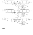
- Fig. 1 shows a portion of a three-phase cable system, in particular, a junction of power cable sections 5 of the three-phase cable system is shown.
- Each phase L1, L2 and L3 is associated with a power cable with an inner conductor 4 and a cable sheath 3, wherein the cable sheaths 3 of the power cables of the respective phases L1, L2 and L3 are galvanically connected to each other.
- a sheath voltage 1 is provided in each case, which serves to dissipate transient overvoltages by the Mantelschreibsableiter 1 due to its non-linear resistance characteristic from its high-impedance operating condition in which the Mantelschreibsableiter has a constant capacity, briefly in a good conductive state passes.
- the energy of the leakage current converts the surge arrester into heat. If the energy in the surge arrester exceeds the maximum dissipatable energy, the surge arrester can be destroyed so that there is no connection between the respective cable sheath 3 and the earth potential.
- a measuring and monitoring system 9 is provided for each jacket voltage arrester 1, although the functions of the individual measuring and monitoring systems 9 can also be implemented in a common measuring and monitoring unit.
- Each measuring and monitoring system 9 is according to Fig. 1 grounded (see reference numeral 10) and has a test signal source 6 for generating a test signal, a measuring device 7 for detecting and evaluating a tapped at the respective Mantelwoodsableiter 1 measurement signal and a partial discharge measuring device 8 for additionally performing a partial discharge measurement.
- the test signal generated by the test signal source 6 is fed into a measuring circuit or a measuring loop, which contains the respectively to be monitored Mantelschreibsableiter 1, wherein the measuring device 7 a tapped at the respective measurement loop measurement signal, which depends on the frequency-dependent impedance of each to be monitored Mantelschreibsableiters changed, detected to close by evaluation of this measurement signal on the current state of the Mantelschreibsableiters 1.
- the frequency spectrum of the test signal impressed into the respective arrester branch is preferably analyzed, which changes depending on the state of the respective jacket voltage arrester (state 1: the arrester is in operation and fully functional and has a constant capacitance; : the arrester has gone into the conductive state, and a conductive channel has arisen in the arrester, state 3: the arrester is destroyed and there is no connection between the cable sheath 3 and the ground potential 10).
- test signal As a test signal from the respective test signal source 6 calibration pulses, preferably low-voltage pulses or the like, are generated, which are in the shield system of a cable sleeve, to which the respective jacket voltage 1 is attached, fed.
- the test signal can also be a signal which changes with respect to its waveform, amplitude and / or repetition rate or frequency, which may in particular also be a wobble signal, ie. a signal with a periodically changed frequency from a start value to an end value.
- the test signal may be a noise signal, wherein preferably a signal with a band-limited white noise may be used.
- the coupling of the test signal into the respective measuring loop takes place via a device 2 which fulfills several tasks.
- the device 2 which is preferably configured in the form of a sensor
- the test signal is fed into the respective measuring loop.
- the device 2 serves for decoupling the measurement signal, ie the test signal response, in order to supply the measurement signal to the respective measuring device 7.
- the device 2 is used in the in Fig. 1 illustrated embodiment also for partial discharge measurement in combination with the partial discharge measuring device 8 contained in the monitoring and measuring system 9, since the measurement signal in addition to the actual test signal and partial discharge pulses that may arise in the insulation of the cable system may contain.
- the coupling of the test signal into the respective measuring loop as well as the decoupling of the measuring signal tapped off at the respective measuring loop does not require a galvanic connection to the respective jacket voltage arrester 1, so that the test signal feed and the measuring signal decoupling can each be decoupled from the sheath voltage conductor 1.
- an inductive sensor 2 eg a "high frequency current transformer” sensor
- Such an inductive sensor 2 may consist of only one part or of several parts exist and in the middle of the sensor have an opening, in which the respective Ableiterzutechnisch to be measured is placed.
- the inductive sensor has a ground connection and is separated from the respective arrester supply line by an insulation.
- Two-part inductive sensors are known as split-core HFCTs and allow mounting without the prior opening of sheath voltage connections.
- the senor 2 provided for test signal coupling and measuring signal decoupling is preferably arranged in the vicinity of the respectively to be monitored Mantelthesesableiters 1, wherein the sensor 2, for example, both above the Mantelschreibsableiters 1 and below the Mantelschreibsableiters 2 can be located.
- the sensor 2 is located above the jacket voltage conductor 1 in order not to impair the sensitivity of the partial discharge measurement.
- the measuring signal decoupled via the respective sensor 2 is supplied to the measuring device 7 contained in the respective measuring and monitoring system 9, wherein the measuring device 7 is preferably designed such that it varies the frequency spectrum of the measuring signal, which varies depending on the frequency-dependent impedance of the jacket voltage diverter 1, evaluates to close the state of the Manteldozenssableiters 1.
- the measuring device 7 is preferably designed such that it varies the frequency spectrum of the measuring signal, which varies depending on the frequency-dependent impedance of the jacket voltage diverter 1, evaluates to close the state of the Mantelwoodsableiters 1.
- each state of the Mantelschreibsableiters 1 may be associated with a specific amplitude and position of the resonant frequency, so that when a change in the amplitude or position of the resonance frequency in a simple manner on the state of the Mantelschreibsableiters 1 can be concluded.
- the current measurement curve of the measurement signal can be compared with a previously recorded and stored frequency spectrum of a functional sheath voltage surge arrester.
- the measurement described above which preferably takes place in the frequency range, may under certain circumstances take place in an environment superimposed by interference signals, which makes it more difficult to evaluate the measurement signal superimposed by such interference signals.
- various signal processing methods for example correlation methods
- the actual test signal or the test signal response can be found again in the measurement signal superimposed with the interference signals, thus increasing the accuracy in monitoring the condition of the respective jacket voltage arrester 1.
- the monitoring method described can be used both in cable systems in operation and in cable systems separated from the power supply network.
- the monitoring method is carried out during operation, ie, online, in a live cable system, after the one-time installation of the above-mentioned monitoring and measuring systems 9 no operation of the monitoring method on the individual Mantelschreibsableitern 1 longer required.
- the monitoring of the Mantelschreibsableiter 1 preferably takes place computer or computer-aided, wherein the evaluation of the measured data takes place in a computing unit, which is preferably not directly to the individual Mantelschreibsableitern 1 or in the vicinity of the monitored cable system.
- the in Fig. 1 shown measuring and monitoring systems 9 may be integrated in a computing unit, which is connected via a bus system with the individual sensors 2.
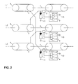
- Fig. 2 shows a second embodiment of the present invention, wherein in Fig. 2 those components which the in Fig. 1 shown components are provided with the same reference numerals.
- FIG. 2 embodiment shown differs from that in Fig. 1 shown embodiment only in that the individual sheath voltage 1 are connected to ground and therefore each have a ground 11.
- Each sensor 2 is located above the respectively to be monitored Manteltensionsableiters 1 and is similar to Fig. 1 connected to the respective measuring and monitoring system 9. Otherwise, the functioning of the in Fig. 2 illustrated embodiment the in Fig. 1 illustrated embodiment, so that the above explanations to Fig. 1 can be referenced.
Landscapes
- Physics & Mathematics (AREA)
- General Physics & Mathematics (AREA)
- Testing Relating To Insulation (AREA)
Abstract
Description
Verfahren und Vorrichtung zur Überwachung eines Mantelspannungsableiters eines KabelsystemsMethod and device for monitoring a jacket voltage diverter of a cable system
Die vorliegende Erfindung betrifft ein Verfahren sowie eine Vorrichtung zur Überwachung eines Mantelspannungsableiters eines Kabelsystems, insbesondere eines Hoch- oder Höchstspannungskabelsystems eines Energieversorgungssystems.The present invention relates to a method and a device for monitoring a jacket voltage diverter of a cable system, in particular a high or extra high voltage cable system of a power supply system.
Mantelspannungsableiter werden als Überspannungsableiter in Energieversorgungssystemen eingesetzt, um transiente Überspannungen, wie beispielsweise Schaltüberspannungen und Blitzüberspannungen, zu begrenzen und ein Versagen der Isolation des jeweiligen Betriebsmittels zu verhindern. Dabei werden herkömmlicherweise Mantelspannungsableiter bei Kabelsystemen an Muffen installiert und befinden sich typischerweise zwischen dem Mantel desjenigen Kabels, das mit der Muffe verbunden ist, und der Erdung oder zwischen zwei Mänteln zweier Kabelphasen, wenn es sich um ein Kabelsystem mit so genannten Auskreuzmuffen oder Cross-Bonding-Muffen handelt. Bei mehrphasigen Kabelsystemen besteht die Aufgabe der einzelnen Mantelspannungsableiter darin, die Mantelschirme der einzelnen Phasen auszukreuzen, um indizierte Mantelstromverluste zu reduzieren und im Fehlerfall Potentialdifferenzen zwischen den einzelnen Kabelmänteln zu begrenzen oder transiente Überspannungen in die Erde abzuleiten.Shock absorbers are used as surge arresters in power supply systems to limit transient overvoltages, such as switching overvoltages and lightning overvoltages, and to prevent failure of the isolation of the respective equipment. In this case, cable surge arresters are conventionally installed in cable systems on sleeves and are typically located between the jacket of the cable connected to the sleeve and the ground or between two sheaths of two cable phases, if it is a cable system with so-called Auskreuzmuffen or cross-bonding Joints. In multi-phase cable systems, the task of the individual sheath voltage surge is to cross the shrouds of the individual phases to reduce indexed sheath current losses and to limit potential differences between the individual cable sheaths in case of failure or to dissipate transient overvoltages in the earth.
Um einen ordnungsgemäßen Betrieb derartiger Mantelspannungsableiter zu gewährleisten, ist ein zuverlässiges Ableitermonitoring unerlässlich, um den aktuellen Zustand des jeweiligen Mantelspannungsableiters überwachen zu können. Wie bereits erläutert worden ist, besteht die wesentliche Funktion eines Mantelspannungsableiters darin, transiente Überspannungen abzuführen, indem der Mantelspannungsableiter aufgrund seiner nicht linearen Widerstandscharakteristik aus einem hochohmigen Betriebszustand kurzzeitig in einen gut leitenden Zustand übergeht. Die Energie des dabei auftretenden Ableitstromes wandelt der Mantelspannungsableiter in Wärme um. Übersteigt die Energie im Ableiter die maximal abführbare Energie, kann neben dem eigentlichen Betriebszustand und dem leitfähigen Zustand ein weiterer Zustand auftreten, in dem der Ableiter zerstört ist und keine Verbindung zwischen dem Kabelmantel und dem Erdpotential besteht.In order to ensure proper operation of such sheath voltage arresters, a reliable arrester monitoring is essential to be able to monitor the current state of the respective sheath voltage arrester. As has already been explained, the essential function of a jacket voltage arrester is to dissipate transient overvoltages, in that the jacket voltage arrester transiently changes from a high-resistance operating state to a good conducting state due to its non-linear resistance characteristic. The energy of the leakage current occurring converts the jacket voltage arrester into heat. If the energy in the arrester exceeds the maximum dissipatable energy, a further condition can occur in addition to the actual operating state and the conductive state in which the arrester is destroyed and there is no connection between the cable sheath and the earth potential.
Der vorliegenden Erfindung liegt die Aufgabe zugrunde, ein Verfahren und eine Vorrichtung zur Überwachung eines Mantelspannungsableiters eines Kabelsystems bereitzustellen, womit auf einfache Art und Weise zuverlässig der Zustand des Mantelspannungsableiters überwacht werden kann.The present invention has for its object to provide a method and apparatus for monitoring a Mantelspannungsableiters of a cable system, which can be easily monitored in a simple manner, the condition of the Mantelspannungsableiters.
Diese Aufgabe wird erfindungsgemäß durch eine Vorrichtung zur Überwachung eines Mantelspannungsableiters eines Kabelsystems mit den Merkmalen des Patentanspruches 1 bzw. ein Verfahren mit den Merkmalen des Patentanspruches 17 gelöst. Die abhängigen Patentansprüche definieren bevorzugte und/oder vorteilhafte Ausführungsformen der vorliegenden Erfindung.This object is achieved by a device for monitoring a Mantelspannungsableiters a cable system with the features of
Erfindungsgemäß wird zur Überwachung eines Mantelspannungsableiters eines Kabelsystems ein Prüfsignal in eine Messschleife, welche den Mantelspannungsableiter beinhaltet, eingespeist, um durch Auswertung eines an der Messschleife abgegriffenen Messsignals, welches von der frequenzabhängigen Impedanz des Mantelspannungsableiters abhängig ist, auf den Zustand des Mantelspannungsableiters schließen zu können.According to the invention for monitoring a Mantelspannungsableiters a cable system, a test signal in a measuring loop, which includes the Mantelspannungsableiter fed to be able to conclude by evaluating a tapped on the measurement loop measurement signal, which depends on the frequency-dependent impedance of the Mantelspannungsableiters on the state of Mantelspannungsableiters.
Vorzugsweise wird dabei das Frequenzspektrum des Messsignals ausgewertet, wobei gemäß einer bevorzugten Ausführungsform die Ableiterimpedanz und die Kabelimpedanz zu einem Schwingkreis verschaltet sind, so dass der Mantelzustand beispielsweise aus der Lage oder Amplitude der Resonanzfrequenz dieses Schwingkreises abgeleitet werden kann.Preferably, the frequency spectrum of the measuring signal is evaluated, wherein in accordance with a preferred embodiment, the arrester impedance and the cable impedance are connected to a resonant circuit, so that the shell state can be derived for example from the position or amplitude of the resonant frequency of this resonant circuit.
Als Prüfsignal kann ein Kalibrierimpuls, vorzugsweise ein Niederspannungsimpuls, in die Messschleife eingeprägt werden. Ebenso ist es möglich, ein sich hinsichtlich seiner Kurvenform, Amplitude und/oder Frequenz über die Zeit variierendes Prüfsignal zuzuführen, wobei es sich bei dem Prüfsignal auch um ein Rauschsignal oder ein Wobble-Signal handeln kann. Die Einspeisung des Prüfsignals kann vorzugsweise in das Schirmsystem einer Kabelmuffe des zu überwachenden Kabelsystems erfolgen, wobei ebenfalls vorzugsweise das Einspeisen des Prüfsignals und das Erfassen des Messsignals durch ein und dieselbe Einrichtung vorgenommen wird, welche darüber hinaus auch zum Messen von Teilentladungen ausgestaltet sein kann.As a test signal, a calibration pulse, preferably a low-voltage pulse, can be impressed into the measurement loop. It is likewise possible to supply a test signal which varies over time with regard to its waveform, amplitude and / or frequency, wherein the test signal can also be a noise signal or a wobble signal. The feeding of the test signal can preferably be carried out in the shielding system of a cable sleeve of the cable system to be monitored, wherein preferably also the feeding of the test signal and the detection of the measurement signal is performed by one and the same device, which may also be configured to measure partial discharges.
Gemäß einer bevorzugten Ausführungsform kann die Einspeisung des Prüfsignals mittels eines in der Nähe des Mantelspannungsableiters angebrachten Sensors erfolgen, wobei das Einspeisen bzw. Einkoppeln des Prüfsignals und das Erfassen bzw. Auskoppeln des Messsignals vorzugsweise galvanisch entkoppelt erfolgt, wobei hierzu beispielsweise induktive Sensoren eingesetzt werden können.According to a preferred embodiment, the feeding of the test signal by means of a mounted in the vicinity of the Mantelspannungsableiters sensor, wherein the feeding or coupling of the test signal and the detection or decoupling of the measurement signal is preferably galvanically decoupled, for this purpose, for example, inductive sensors can be used.
Die vorliegende Erfindung ermöglicht eine zuverlässige kontinuierliche Überwachung von Mantelspannungsableitern während des Betriebs des jeweiligen Kabelsystems, wobei die Überwachung automatisch rechnergestützt erfolgen kann, ohne dass nach der einmaligen Installation eine Bedienung am jeweiligen Mantelspannungsableiter notwendig ist. Die Auswertung des Messsignals bzw. der entsprechenden Messdaten kann in einer Recheneinheit erfolgen, die sich nicht direkt am Mantelspannungsableiter bzw. am Kabelsystem befinden muss.The present invention allows a reliable continuous monitoring of Mantelspannungsableitern during operation of the respective cable system, the monitoring can be done automatically computer-aided, without an operation on the respective Mantelspannungsableiter is necessary after the single installation. The evaluation of the measurement signal or the corresponding measurement data can be carried out in a computing unit that does not have to be located directly on the sheath voltage surge arrester or on the cable system.
Die Erfindung eignet sich bevorzugt zur Überwachung des Zustands von Mantelspannungsableitern eines Hoch-/Höchstspannungskabelsystems, welches Bestandteil eines Energieversorgungssystems ist, ohne jedoch darauf beschränkt zu sein.The invention is preferably useful for monitoring the condition of sheath voltage surge arresters of a high voltage / extra high voltage cable system which is part of, but not limited to, a power supply system.
Die Erfindung wird nachfolgend näher unter Bezugnahme auf die beigefügte Zeichnung anhand bevorzugter Ausführungsbeispiele erläutert.
-
Fig. 1 zeigt ein dreiphasiges Kabelsystem mit einer Vorrichtung zur Überwachung des Zustands von Mantelspannungsableitern dieses dreiphasigen Kabelsystems gemäß einer ersten Ausführungsform der vorliegenden Erfindung, und -
Fig. 2 zeigt ein dreiphasiges Kabelsystem mit einer Vorrichtung zur Überwachung des Zustands von Mantelspannungsableitern dieses dreiphasigen Kabelsystems gemäß einem zweiten Ausführungsbeispiel der vorliegenden Erfindung.
-
Fig. 1 shows a three-phase cable system with a device for monitoring the state of Mantelspannungsableitern this three-phase cable system according to a first embodiment of the present invention, and -
Fig. 2 shows a three-phase cable system with a device for monitoring the state of Mantelspannungsableitern this three-phase cable system according to a second embodiment of the present invention.
Zwischen den Kabelmänteln 3 zweier Energiekabelteilstrecken einer Phase ist jeweils ein Mantelspannungsableiter 1 vorgesehen, welcher zum Abführen von transienten Überspannungen dient, indem der Mantelspannungsableiter 1 aufgrund seiner nicht linearen Widerstandscharakteristik aus seinem hochohmigen Betriebszustand, in dem der Mantelspannungsableiter eine konstante Kapazität besitzt, kurzzeitig in einen gut leitenden Zustand übergeht. Die Energie des Ableitstroms wandelt der Mantelspannungsableiter in Wärme um. Übersteigt die Energie im Mantelspannungsableiter die maximal abführbare Energie, kann der Mantelspannungsableiter zerstört werden, so dass keine Verbindung zwischen dem jeweiligen Kabelmantel 3 und dem Erdpotential besteht.Between the
Um den Zustand der einzelnen Mantelspannungsableiter 1 in
Das von der Prüfsignalquelle 6 erzeugte Prüfsignal wird in einen Messkreis oder eine Messschleife, welche den jeweils zu überwachenden Mantelspannungsableiter 1 beinhaltet, eingespeist, wobei die Messeinrichtung 7 ein an der jeweiligen Messschleife abgegriffenes Messsignal, welches sich abhängig von der frequenzabhängigen Impedanz des jeweils zu überwachenden Mantelspannungsableiters verändert, erfasst, um durch Auswertung dieses Messsignals auf den jeweils aktuellen Zustand des Mantelspannungsableiters 1 zu schließen. Zur Überwachung des jeweiligen Mantelspannungsableiters wird vorzugsweise das Frequenzspektrum des in den jeweiligen Ableiterzweig eingeprägten Prüfsignals analysiert, welches sich abhängig von dem Zustand des jeweiligen Mantelspannungsableiters verändert (Zustand 1: der Ableiter befindet sich im Betrieb und ist voll funktionsfähig und besitzt eine konstante Kapazität; Zustand 2: der Ableiter ist in den leitfähigen Zustand übergegangen, und ein leitfähiger Kanal ist im Ableiter entstanden; Zustand 3: der Ableiter ist zerstört, und es besteht keine Verbindung zwischen dem Kabelmantel 3 und dem Erdpotential 10). Durch Auswertung der frequenzabhängigen Impedanz der jeweiligen Messschleife, welche sich in Abhängigkeit vom Zustand des Mantelspannungsableiters 1 verändert, kann zuverlässig auf den Zustand des Mantelspannungsableiters 1 geschlossen werden.The test signal generated by the
Als Prüfsignal können von der jeweiligen Prüfsignalquelle 6 Kalibrierimpulse, vorzugsweise Niederspannungspulse oder dergleichen, erzeugt werden, die in das Schirmssystem einer Kabelmuffe, an welcher der jeweilige Mantelspannungsableiter 1 angebracht ist, eingespeist werden. Allgemein kann es sich jedoch bei dem Prüfsignal auch um ein Signal handeln, welches sich hinsichtlich seiner Kurvenform, Amplitude und/oder Wiederholrate bzw. Frequenz verändert, wobei es sich insbesondere auch um ein Wobble-Signal handeln kann, d.h. ein Signal mit einer sich periodisch von einem Startwert zu einem Endwert hin veränderten Frequenz. Ebenso kann es sich bei dem Prüfsignal um ein Rauschsignal handeln, wobei vorzugsweise ein Signal mit einem bandbegrenzten weißen Rauschen eingesetzt werden kann.As a test signal from the respective
Gemäß
Die Einkopplung des Prüfsignals in die jeweilige Messschleife sowie die Auskopplung des an der jeweiligen Messschleife abgegriffenen Messsignals erfordert gemäß einer bevorzugten Ausführungsform keine galvanische Verbindung zu dem jeweiligen Mantelspannungsableiter 1, so dass die Prüfsignaleinspeisung und die Messsignalauskopplung jeweils von dem Mantelspannungsableiter 1 entkoppelt erfolgen kann. Zu diesem Zweck kann beispielsweise ein induktiver Sensor 2 (z.B. ein "High Frequency Current Transformer"-Sensor) verwendet werden. Ein derartiger induktiver Sensor 2 kann aus lediglich einem Teil oder aus mehreren Teilen bestehen und in der Mitte des Sensors eine Öffnung aufweisen, in die die jeweils zu vermessende Ableiterzuleitung gelegt ist. Der induktive Sensor besitzt einen Masseanschluss und ist durch eine Isolation von der jeweiligen Ableiterzuleitung getrennt. Induktive Sensoren mit zwei Teilen sind als sogenannte "Split Core HFCTs" bekannt und ermöglichen eine Montage ohne die vorherige Öffnung von Mantelspannungsableiterverbindungen.According to a preferred embodiment, the coupling of the test signal into the respective measuring loop as well as the decoupling of the measuring signal tapped off at the respective measuring loop does not require a galvanic connection to the respective
Allgemein ist der zur Prüfsignaleinkopplung und Messsignalauskopplung vorgesehene Sensor 2 vorzugsweise in der Nähe des jeweils zu überwachenden Mantelspannungsableiters 1 angeordnet, wobei sich der Sensor 2 beispielsweise sowohl oberhalb des Mantelspannungsableiters 1 als auch unterhalb des Mantelspannungsableiters 2 befinden kann. Für die zusätzliche Durchführung einer Teilentladungsmessung kann es vorteilhaft sein, wenn sich der Sensor 2 oberhalb des Mantelspannungsableiters 1 befindet, um nicht die Empfindlichkeit der Teilentladungsmessung zu beeinträchtigen.In general, the
Das über den jeweiligen Sensor 2 ausgekoppelte Messsignal wird der in dem jeweiligen Mess- und Überwachungssystem 9 enthaltenen Messeinrichtung 7 zugeführt wobei die Messeinrichtung 7 vorzugsweise derart ausgestaltet ist, dass sie das Frequenzspektrum des Messsignals, welches sich abhängig von der frequenzabhängigen Impedanz des Mantelspannungsableiters 1 verändert, auswertet, um auf den Zustand des Mantelspannungsableiters 1 zu schließen. Die in
Die zuvor beschriebene Messung, welche vorzugsweise im Frequenzbereich erfolgt, kann unter Umständen in einer von Störsignalen überlagerten Umgebung stattfinden, wodurch die Auswertung des von derartigen Störsignalen überlagerten Messsignals erschwert wird. Durch verschiedene Signalverarbeitungsverfahren (beispielsweise Korrelationsverfahren) kann das eigentliche Prüfsignal bzw. die Prüfsignalantwort in dem mit den Störsignalen überlagerten Messsignal wiederaufgefunden werden, um somit die Genauigkeit bei der Überwachung des Zustands des jeweiligen Mantelspannungsableiters 1 zu erhöhen.The measurement described above, which preferably takes place in the frequency range, may under certain circumstances take place in an environment superimposed by interference signals, which makes it more difficult to evaluate the measurement signal superimposed by such interference signals. By means of various signal processing methods (for example correlation methods), the actual test signal or the test signal response can be found again in the measurement signal superimposed with the interference signals, thus increasing the accuracy in monitoring the condition of the respective
Das zuvor anhand von
Das in
Claims (19)
mit einer Prüfsignalquelle (6) zum Erzeugen eines in eine Messschleife, welche den Mantelspannungsableiter (1) umfasst, einzuspeisenden Prüfsignals, und
mit einer Messeinrichtung (7) zum Erfassen eines an der Messschleife abgegriffenen Messsignals, welches von einer frequenzabhängigen Impedanz des Mantelspannungsableiters (1) abhängig ist, um durch Auswertung des Messsignals auf einen Zustand des Mantelspannungsableiters (1) zu schließen.Device for monitoring a jacket voltage arrester (1) of a cable system (L1-L3, 3-5),
with a test signal source (6) for generating a test signal to be fed into a measuring loop, which comprises the jacket voltage arrester (1), and
with a measuring device (7) for detecting a tapped on the measuring loop measuring signal, which is dependent on a frequency-dependent impedance of the Mantelspannungsableiters (1) to close by evaluation of the measuring signal to a state of the Mantelspannungsableiters (1).
dadurch gekennzeichnet,
dass die Prüfsignalquelle (6) ein Pulssignal, ein Rauschsignal oder ein sich hinsichtlich seiner Kurvenform, Amplitude und/oder Frequenz periodisch veränderndes Signal als das Prüfsignal erzeugt.Device according to claim 1,
characterized,
that the test signal source (6) generates a pulse signal, a noise signal or a periodically changing with respect to its waveform, amplitude and / or frequency signal as the test signal.
dadurch gekennzeichnet,
dass die Prüfsignalquelle (6) derart mit dem Kabelsystem (L1-L3, 3-5) gekoppelt ist, dass das Prüfsignal in ein Schirmsystem einer Kabelmuffe, an welcher der Mantelspannungsableiter (1) angebracht ist, eingespeist wird.Apparatus according to claim 1 or claim 2,
characterized,
that the test signal source (6) is so coupled to the cable system (L1-L3, 3-5) that the test signal is in a screen system of a cable sleeve, is at which the Mantelspannungsableiter (1) attached fed.
dass die Messeinrichtung (7) derart ausgestaltet ist, dass sie zur Erkennung des Zustands des Mantelspannungsableiters (1) eine Lage oder Amplitude einer Resonanzfrequenz des Schwingkreises auswertet.Apparatus according to claim 12, characterized in that the Mantelspannungsableiter (1) is connected in such a way with the cable system (L1-L3, 3-5) and the measuring device (7) that the impedance of the Mantelspannungsableiters (1) and an impedance of the cable system ( L1-L3, 3-5) are components of a resonant circuit, and
in that the measuring device (7) is designed in such a way that it evaluates a position or amplitude of a resonant frequency of the resonant circuit in order to detect the condition of the jacket voltage arrester (1).
umfassend die Schritte
Einspeisen eines Prüfsignals in eine Messschleife, welche den Mantelspannungsableiter (1) umfasst, und
Erfassen eines an der Messschleife abgegriffenen Messsignals, welches von einer frequenzabhängigen Impedanz des Mantelspannungsableiters (1) abhängig ist, um durch Auswertung des Messsignals auf einen Zustand des Mantelspannungsableiters (1) zu schließen.Method for monitoring a jacket voltage arrester (1) of a cable system (L1-L3, 3-5),
comprising the steps
Feeding a test signal into a measuring loop which comprises the sheath voltage conductor (1), and
Detecting a tapped on the measuring loop measurement signal, which is dependent on a frequency-dependent impedance of the Mantelspannungsableiters (1) to close by evaluation of the measurement signal to a state of the Mantelspannungsableiters (1).
Priority Applications (2)
| Application Number | Priority Date | Filing Date | Title |
|---|---|---|---|
| EP10005744.7A EP2392934B1 (en) | 2010-06-02 | 2010-06-02 | Method and device for monitoring a sheath voltage arrester of a cable system |
| US13/151,006 US9146268B2 (en) | 2010-06-02 | 2011-06-01 | Method and device for monitoring a sheath voltage arrester of a cable system |
Applications Claiming Priority (1)
| Application Number | Priority Date | Filing Date | Title |
|---|---|---|---|
| EP10005744.7A EP2392934B1 (en) | 2010-06-02 | 2010-06-02 | Method and device for monitoring a sheath voltage arrester of a cable system |
Publications (3)
| Publication Number | Publication Date |
|---|---|
| EP2392934A1 true EP2392934A1 (en) | 2011-12-07 |
| EP2392934A8 EP2392934A8 (en) | 2012-02-15 |
| EP2392934B1 EP2392934B1 (en) | 2019-02-06 |
Family
ID=43217279
Family Applications (1)
| Application Number | Title | Priority Date | Filing Date |
|---|---|---|---|
| EP10005744.7A Active EP2392934B1 (en) | 2010-06-02 | 2010-06-02 | Method and device for monitoring a sheath voltage arrester of a cable system |
Country Status (2)
| Country | Link |
|---|---|
| US (1) | US9146268B2 (en) |
| EP (1) | EP2392934B1 (en) |
Cited By (4)
| Publication number | Priority date | Publication date | Assignee | Title |
|---|---|---|---|---|
| WO2016190823A1 (en) * | 2015-05-28 | 2016-12-01 | Em Elektri̇k Malzemeleri̇ Yükleni̇m Sanayi̇ Ti̇caret Anoni̇m Şi̇rketi̇ | Link box with built-in partial discharge sensor |
| CN111458597A (en) * | 2020-02-06 | 2020-07-28 | 云南电网有限责任公司电力科学研究院 | Fault positioning method based on lightning overvoltage phase transmission characteristic |
| WO2020151986A1 (en) * | 2019-01-23 | 2020-07-30 | Omicron Energy Solutions Gmbh | Inspecting sheath voltage limiters |
| CN113608031A (en) * | 2021-08-04 | 2021-11-05 | 北京英瑞来科技有限公司 | Method and device for monitoring impulse impedance of transformer substation lightning arrester |
Families Citing this family (5)
| Publication number | Priority date | Publication date | Assignee | Title |
|---|---|---|---|---|
| CN104866644B (en) * | 2015-04-03 | 2018-06-22 | 华南理工大学 | A kind of inductive type current-limited arrester optimum design method based on formula of enumerating |
| CN111239546B (en) * | 2020-02-06 | 2021-07-27 | 云南电网有限责任公司电力科学研究院 | Lightning overvoltage on-line distance measurement and fault location method |
| CN113567802A (en) * | 2020-04-29 | 2021-10-29 | 马克西姆综合产品公司 | System and method for cable shield fault detection and protection |
| US11183828B1 (en) | 2020-06-12 | 2021-11-23 | hvGrid-tech Inc. | Device with health monitoring |
| CN113376470B (en) * | 2021-07-08 | 2022-11-22 | 广西电网有限责任公司电力科学研究院 | Remote monitoring system for running state of lightning protection device |
Citations (2)
| Publication number | Priority date | Publication date | Assignee | Title |
|---|---|---|---|---|
| JPH031476A (en) * | 1989-02-16 | 1991-01-08 | Fuji Electric Co Ltd | Sensing device for leak current of lightning arrester |
| DE19629481A1 (en) * | 1996-07-12 | 1998-01-15 | Siemens Ag | Circuit arrangement for a high-voltage cable system |
Family Cites Families (10)
| Publication number | Priority date | Publication date | Assignee | Title |
|---|---|---|---|---|
| US4161012A (en) * | 1977-03-02 | 1979-07-10 | Joslyn Mfg. And Supply Co. | High voltage protection apparatus |
| GB9005827D0 (en) * | 1990-03-15 | 1990-05-09 | Raychem Gmbh | Electrical protection apparatus |
| US5312361A (en) | 1991-09-13 | 1994-05-17 | Zadini Filiberto P | Automatic cannulation device |
| US6100699A (en) * | 1997-11-12 | 2000-08-08 | At&T Corp. | Faulty filter detection technique |
| US6651020B2 (en) * | 1997-12-24 | 2003-11-18 | Edward S. More | Method and apparatus for economical drift compensation in high resolution measurements |
| DE10345658B3 (en) * | 2003-09-25 | 2005-04-28 | Siemens Ag | Device for monitoring the leakage current of a surge arrester |
| DE102005024206B4 (en) * | 2005-05-25 | 2007-03-15 | Tridelta Überspannungsableiter Gmbh | Surge arrester with cage design |
| US7656639B2 (en) * | 2006-06-22 | 2010-02-02 | Cooper Technologies Company | Retainer for surge arrester disconnector |
| US7843188B2 (en) * | 2008-05-20 | 2010-11-30 | The Boeing Company | Remote sensor network powered inductively from data lines |
| US20100123356A1 (en) * | 2008-11-14 | 2010-05-20 | General Electric Company | Resonance mitigation system and method |
-
2010
- 2010-06-02 EP EP10005744.7A patent/EP2392934B1/en active Active
-
2011
- 2011-06-01 US US13/151,006 patent/US9146268B2/en active Active
Patent Citations (2)
| Publication number | Priority date | Publication date | Assignee | Title |
|---|---|---|---|---|
| JPH031476A (en) * | 1989-02-16 | 1991-01-08 | Fuji Electric Co Ltd | Sensing device for leak current of lightning arrester |
| DE19629481A1 (en) * | 1996-07-12 | 1998-01-15 | Siemens Ag | Circuit arrangement for a high-voltage cable system |
Non-Patent Citations (5)
| Title |
|---|
| FRUTH B A ET AL: "Combination of frequency spectrum analysis and partial discharge pattern recording", ELECTRICAL INSULATION, 1994., CONFERENCE RECORD OF THE 1994 IEEE INTER NATIONAL SYMPOSIUM ON PITTSBURGH, PA, USA 5-8 JUNE 1994, NEW YORK, NY, USA,IEEE, 5 June 1994 (1994-06-05), pages 296 - 300, XP010139506, ISBN: 978-0-7803-1942-4, DOI: 10.1109/ELINSL.1994.401508 * |
| OSZTERMAYER J; CARDILLO E; MARKALOUS S M; WIMMER R; LENZ M; HOEK S M; FESER K: "Asset management based on improved online monitoring systems applied to a 110/380 kV substation", 2003 IEEE BOLOGNA POWERTECH, 23 June 2003 (2003-06-23) - 26 June 2003 (2003-06-26), pages 1 - 5, XP002614600 * |
| P. MOHAUPT; M. GAMLIN; R. GLEYVOD; J. KRAUS; G. VOIGT: "High Voltage Testing using Series Resonance with Variable Frequency", May 2000 (2000-05-01), pages 1 - 6, XP002614599, Retrieved from the Internet <URL:http://www.haefely.com/pdf/scientific/e1-85.pdf> [retrieved on 20101215] * |
| PARMIGIANI B; QUAGGIA D; ELLI E; FRANCHINA S: "ZINC OXIDE SHEATH VOLTAGE LIMITER FOR HV AND EHV POWER CABLE: FIELD EXPERIENCE AND LABORATORY TESTS", IEEE TRANSACTIONS ON POWER DELIVERY, vol. PWRD-1, no. 1, January 1986 (1986-01-01), pages 164 - 170, XP002614598 * |
| PETRY W ET AL: "EINLEITERKABEL MIT AUSGEKREUZTEN MAENTELN", ELEKTRIZITAETSWIRTSCHAFT, VEREINIGUNG DEUTSCHER ELEKTRIZITAETZSWERKE, FRA, DE, vol. 70, no. 26, 20 December 1971 (1971-12-20), pages 753 - 761, XP002045842, ISSN: 0013-5496 * |
Cited By (8)
| Publication number | Priority date | Publication date | Assignee | Title |
|---|---|---|---|---|
| WO2016190823A1 (en) * | 2015-05-28 | 2016-12-01 | Em Elektri̇k Malzemeleri̇ Yükleni̇m Sanayi̇ Ti̇caret Anoni̇m Şi̇rketi̇ | Link box with built-in partial discharge sensor |
| GB2543467A (en) * | 2015-05-28 | 2017-04-19 | Em Elektrik Malzemeleri Yuklenim Sanayi Ticaret Anonim Sirketi | Link box with built-in partial discharge sensor |
| GB2543467B (en) * | 2015-05-28 | 2021-03-03 | Em Elektrik Malzemeleri Yuklenim Sanayi Ticaret Anonim Sirketi | Link box with built-in partial discharge sensor |
| WO2020151986A1 (en) * | 2019-01-23 | 2020-07-30 | Omicron Energy Solutions Gmbh | Inspecting sheath voltage limiters |
| CN111458597A (en) * | 2020-02-06 | 2020-07-28 | 云南电网有限责任公司电力科学研究院 | Fault positioning method based on lightning overvoltage phase transmission characteristic |
| CN111458597B (en) * | 2020-02-06 | 2022-06-10 | 云南电网有限责任公司电力科学研究院 | Fault positioning method based on lightning overvoltage phase transmission characteristic |
| CN113608031A (en) * | 2021-08-04 | 2021-11-05 | 北京英瑞来科技有限公司 | Method and device for monitoring impulse impedance of transformer substation lightning arrester |
| CN113608031B (en) * | 2021-08-04 | 2024-02-02 | 北京英瑞来科技有限公司 | Impact impedance monitoring method and device for substation lightning arrester |
Also Published As
| Publication number | Publication date |
|---|---|
| EP2392934A8 (en) | 2012-02-15 |
| EP2392934B1 (en) | 2019-02-06 |
| US20110298475A1 (en) | 2011-12-08 |
| US9146268B2 (en) | 2015-09-29 |
Similar Documents
| Publication | Publication Date | Title |
|---|---|---|
| EP2392934B1 (en) | Method and device for monitoring a sheath voltage arrester of a cable system | |
| DE69916299T2 (en) | METHOD AND DEVICE FOR THE FALL-RELATED LOCALIZATION OF AN ELECTRICAL CABLE | |
| EP0241764A1 (en) | Process and devices for detecting and localizing damages in electrical installations | |
| DE102013207775B4 (en) | Device for detecting a fault in an electrical line | |
| EP1537428B1 (en) | Method and device for detecting sparking and spark erosion in electric machines | |
| EP3524985A1 (en) | Apparatus and method for insulation monitoring with detection of defective outer conductor in an unearthed 3-phase power supply system | |
| DE102012019996A1 (en) | Line network, in particular DC vehicle electrical system for a motor vehicle and method for monitoring a pipeline network to the emergence of an arc | |
| DE102017116613B3 (en) | Method and test device for measuring partial discharge pulses of a shielded cable | |
| EP2264472B1 (en) | Device for measuring the loss factor | |
| AT523525B1 (en) | Electrical circuit arrangement | |
| DE102018126743B3 (en) | Condition analysis of electrical equipment | |
| WO1994007152A1 (en) | Decoupling of a high-frequency error signal from a high-frequency electromagnetic field in a large electric machine | |
| DE69703759T2 (en) | Method and apparatus for fault detection in the shielding of a shielded cable | |
| DE10141349B4 (en) | Non-intrusive event location system and event location method for an overheat detection system | |
| DE102017110955A1 (en) | Detection of a protective conductor failure by means of active shielding | |
| EP2553477B1 (en) | Device and method for diagnosing test objects using a measuring voltage | |
| EP3269015B1 (en) | Method for determining states and locating faults in installed isolated down conductors in the external lightning protection means | |
| EP1001270B1 (en) | Method for testing a ground connection | |
| DE19640821B4 (en) | Method and device for detecting earth faults | |
| EP2151030A1 (en) | Method for correcting a secondary current path of a current converter disturbed by saturations, and electric field device for conducting said method | |
| DE19515068A1 (en) | Arrangement for partial discharge detection in high voltage cables and connection elements | |
| DE3636367C2 (en) | Method and device for determining the distance and direction of earth faults in isolated and compensated power networks | |
| DE10253864A1 (en) | Star connected stator virtual earth connection monitoring procedure for electrical machines uses difference processing with optimized digital filter of null voltage and coil current measurements | |
| AT522128B1 (en) | Checking sheath voltage limiters | |
| EP3680678B1 (en) | Measuring system for detecting interference on lines of an device or a system |
Legal Events
| Date | Code | Title | Description |
|---|---|---|---|
| 17P | Request for examination filed |
Effective date: 20110714 |
|
| AK | Designated contracting states |
Kind code of ref document: A1 Designated state(s): AL AT BE BG CH CY CZ DE DK EE ES FI FR GB GR HR HU IE IS IT LI LT LU LV MC MK MT NL NO PL PT RO SE SI SK SM TR |
|
| AX | Request for extension of the european patent |
Extension state: BA ME RS |
|
| PUAI | Public reference made under article 153(3) epc to a published international application that has entered the european phase |
Free format text: ORIGINAL CODE: 0009012 |
|
| RAP1 | Party data changed (applicant data changed or rights of an application transferred) |
Owner name: OMICRON ENERGY SOLUTIONS GMBH |
|
| STAA | Information on the status of an ep patent application or granted ep patent |
Free format text: STATUS: EXAMINATION IS IN PROGRESS |
|
| 17Q | First examination report despatched |
Effective date: 20171207 |
|
| GRAP | Despatch of communication of intention to grant a patent |
Free format text: ORIGINAL CODE: EPIDOSNIGR1 |
|
| STAA | Information on the status of an ep patent application or granted ep patent |
Free format text: STATUS: GRANT OF PATENT IS INTENDED |
|
| INTG | Intention to grant announced |
Effective date: 20180926 |
|
| RIN1 | Information on inventor provided before grant (corrected) |
Inventor name: KESSLER, OLE Inventor name: PLATH, RONALD Inventor name: EMANUEL, HARALD |
|
| GRAS | Grant fee paid |
Free format text: ORIGINAL CODE: EPIDOSNIGR3 |
|
| GRAA | (expected) grant |
Free format text: ORIGINAL CODE: 0009210 |
|
| STAA | Information on the status of an ep patent application or granted ep patent |
Free format text: STATUS: THE PATENT HAS BEEN GRANTED |
|
| AK | Designated contracting states |
Kind code of ref document: B1 Designated state(s): AL AT BE BG CH CY CZ DE DK EE ES FI FR GB GR HR HU IE IS IT LI LT LU LV MC MK MT NL NO PL PT RO SE SI SK SM TR |
|
| REG | Reference to a national code |
Ref country code: GB Ref legal event code: FG4D Free format text: NOT ENGLISH |
|
| REG | Reference to a national code |
Ref country code: CH Ref legal event code: EP Ref country code: CH Ref legal event code: NV Representative=s name: FELBER UND PARTNER AG, CH Ref country code: AT Ref legal event code: REF Ref document number: 1095248 Country of ref document: AT Kind code of ref document: T Effective date: 20190215 |
|
| REG | Reference to a national code |
Ref country code: IE Ref legal event code: FG4D Free format text: LANGUAGE OF EP DOCUMENT: GERMAN |
|
| REG | Reference to a national code |
Ref country code: DE Ref legal event code: R096 Ref document number: 502010015774 Country of ref document: DE |
|
| REG | Reference to a national code |
Ref country code: LT Ref legal event code: MG4D |
|
| REG | Reference to a national code |
Ref country code: NL Ref legal event code: MP Effective date: 20190206 |
|
| PG25 | Lapsed in a contracting state [announced via postgrant information from national office to epo] |
Ref country code: SE Free format text: LAPSE BECAUSE OF FAILURE TO SUBMIT A TRANSLATION OF THE DESCRIPTION OR TO PAY THE FEE WITHIN THE PRESCRIBED TIME-LIMIT Effective date: 20190206 Ref country code: PT Free format text: LAPSE BECAUSE OF FAILURE TO SUBMIT A TRANSLATION OF THE DESCRIPTION OR TO PAY THE FEE WITHIN THE PRESCRIBED TIME-LIMIT Effective date: 20190606 Ref country code: NL Free format text: LAPSE BECAUSE OF FAILURE TO SUBMIT A TRANSLATION OF THE DESCRIPTION OR TO PAY THE FEE WITHIN THE PRESCRIBED TIME-LIMIT Effective date: 20190206 Ref country code: LT Free format text: LAPSE BECAUSE OF FAILURE TO SUBMIT A TRANSLATION OF THE DESCRIPTION OR TO PAY THE FEE WITHIN THE PRESCRIBED TIME-LIMIT Effective date: 20190206 Ref country code: FI Free format text: LAPSE BECAUSE OF FAILURE TO SUBMIT A TRANSLATION OF THE DESCRIPTION OR TO PAY THE FEE WITHIN THE PRESCRIBED TIME-LIMIT Effective date: 20190206 Ref country code: NO Free format text: LAPSE BECAUSE OF FAILURE TO SUBMIT A TRANSLATION OF THE DESCRIPTION OR TO PAY THE FEE WITHIN THE PRESCRIBED TIME-LIMIT Effective date: 20190506 |
|
| PG25 | Lapsed in a contracting state [announced via postgrant information from national office to epo] |
Ref country code: BG Free format text: LAPSE BECAUSE OF FAILURE TO SUBMIT A TRANSLATION OF THE DESCRIPTION OR TO PAY THE FEE WITHIN THE PRESCRIBED TIME-LIMIT Effective date: 20190506 Ref country code: GR Free format text: LAPSE BECAUSE OF FAILURE TO SUBMIT A TRANSLATION OF THE DESCRIPTION OR TO PAY THE FEE WITHIN THE PRESCRIBED TIME-LIMIT Effective date: 20190507 Ref country code: IS Free format text: LAPSE BECAUSE OF FAILURE TO SUBMIT A TRANSLATION OF THE DESCRIPTION OR TO PAY THE FEE WITHIN THE PRESCRIBED TIME-LIMIT Effective date: 20190606 Ref country code: LV Free format text: LAPSE BECAUSE OF FAILURE TO SUBMIT A TRANSLATION OF THE DESCRIPTION OR TO PAY THE FEE WITHIN THE PRESCRIBED TIME-LIMIT Effective date: 20190206 Ref country code: HR Free format text: LAPSE BECAUSE OF FAILURE TO SUBMIT A TRANSLATION OF THE DESCRIPTION OR TO PAY THE FEE WITHIN THE PRESCRIBED TIME-LIMIT Effective date: 20190206 |
|
| PG25 | Lapsed in a contracting state [announced via postgrant information from national office to epo] |
Ref country code: CZ Free format text: LAPSE BECAUSE OF FAILURE TO SUBMIT A TRANSLATION OF THE DESCRIPTION OR TO PAY THE FEE WITHIN THE PRESCRIBED TIME-LIMIT Effective date: 20190206 Ref country code: AL Free format text: LAPSE BECAUSE OF FAILURE TO SUBMIT A TRANSLATION OF THE DESCRIPTION OR TO PAY THE FEE WITHIN THE PRESCRIBED TIME-LIMIT Effective date: 20190206 Ref country code: SK Free format text: LAPSE BECAUSE OF FAILURE TO SUBMIT A TRANSLATION OF THE DESCRIPTION OR TO PAY THE FEE WITHIN THE PRESCRIBED TIME-LIMIT Effective date: 20190206 Ref country code: DK Free format text: LAPSE BECAUSE OF FAILURE TO SUBMIT A TRANSLATION OF THE DESCRIPTION OR TO PAY THE FEE WITHIN THE PRESCRIBED TIME-LIMIT Effective date: 20190206 Ref country code: ES Free format text: LAPSE BECAUSE OF FAILURE TO SUBMIT A TRANSLATION OF THE DESCRIPTION OR TO PAY THE FEE WITHIN THE PRESCRIBED TIME-LIMIT Effective date: 20190206 Ref country code: EE Free format text: LAPSE BECAUSE OF FAILURE TO SUBMIT A TRANSLATION OF THE DESCRIPTION OR TO PAY THE FEE WITHIN THE PRESCRIBED TIME-LIMIT Effective date: 20190206 Ref country code: RO Free format text: LAPSE BECAUSE OF FAILURE TO SUBMIT A TRANSLATION OF THE DESCRIPTION OR TO PAY THE FEE WITHIN THE PRESCRIBED TIME-LIMIT Effective date: 20190206 |
|
| REG | Reference to a national code |
Ref country code: DE Ref legal event code: R097 Ref document number: 502010015774 Country of ref document: DE |
|
| PG25 | Lapsed in a contracting state [announced via postgrant information from national office to epo] |
Ref country code: SM Free format text: LAPSE BECAUSE OF FAILURE TO SUBMIT A TRANSLATION OF THE DESCRIPTION OR TO PAY THE FEE WITHIN THE PRESCRIBED TIME-LIMIT Effective date: 20190206 Ref country code: PL Free format text: LAPSE BECAUSE OF FAILURE TO SUBMIT A TRANSLATION OF THE DESCRIPTION OR TO PAY THE FEE WITHIN THE PRESCRIBED TIME-LIMIT Effective date: 20190206 |
|
| PLBE | No opposition filed within time limit |
Free format text: ORIGINAL CODE: 0009261 |
|
| STAA | Information on the status of an ep patent application or granted ep patent |
Free format text: STATUS: NO OPPOSITION FILED WITHIN TIME LIMIT |
|
| 26N | No opposition filed |
Effective date: 20191107 |
|
| PG25 | Lapsed in a contracting state [announced via postgrant information from national office to epo] |
Ref country code: MC Free format text: LAPSE BECAUSE OF FAILURE TO SUBMIT A TRANSLATION OF THE DESCRIPTION OR TO PAY THE FEE WITHIN THE PRESCRIBED TIME-LIMIT Effective date: 20190206 |
|
| PG25 | Lapsed in a contracting state [announced via postgrant information from national office to epo] |
Ref country code: SI Free format text: LAPSE BECAUSE OF FAILURE TO SUBMIT A TRANSLATION OF THE DESCRIPTION OR TO PAY THE FEE WITHIN THE PRESCRIBED TIME-LIMIT Effective date: 20190206 |
|
| REG | Reference to a national code |
Ref country code: BE Ref legal event code: MM Effective date: 20190630 |
|
| PG25 | Lapsed in a contracting state [announced via postgrant information from national office to epo] |
Ref country code: TR Free format text: LAPSE BECAUSE OF FAILURE TO SUBMIT A TRANSLATION OF THE DESCRIPTION OR TO PAY THE FEE WITHIN THE PRESCRIBED TIME-LIMIT Effective date: 20190206 |
|
| PG25 | Lapsed in a contracting state [announced via postgrant information from national office to epo] |
Ref country code: IE Free format text: LAPSE BECAUSE OF NON-PAYMENT OF DUE FEES Effective date: 20190602 |
|
| PG25 | Lapsed in a contracting state [announced via postgrant information from national office to epo] |
Ref country code: BE Free format text: LAPSE BECAUSE OF NON-PAYMENT OF DUE FEES Effective date: 20190630 Ref country code: LU Free format text: LAPSE BECAUSE OF NON-PAYMENT OF DUE FEES Effective date: 20190602 |
|
| PG25 | Lapsed in a contracting state [announced via postgrant information from national office to epo] |
Ref country code: FR Free format text: LAPSE BECAUSE OF NON-PAYMENT OF DUE FEES Effective date: 20190630 |
|
| PG25 | Lapsed in a contracting state [announced via postgrant information from national office to epo] |
Ref country code: CY Free format text: LAPSE BECAUSE OF FAILURE TO SUBMIT A TRANSLATION OF THE DESCRIPTION OR TO PAY THE FEE WITHIN THE PRESCRIBED TIME-LIMIT Effective date: 20190206 |
|
| PG25 | Lapsed in a contracting state [announced via postgrant information from national office to epo] |
Ref country code: HU Free format text: LAPSE BECAUSE OF FAILURE TO SUBMIT A TRANSLATION OF THE DESCRIPTION OR TO PAY THE FEE WITHIN THE PRESCRIBED TIME-LIMIT; INVALID AB INITIO Effective date: 20100602 Ref country code: MT Free format text: LAPSE BECAUSE OF FAILURE TO SUBMIT A TRANSLATION OF THE DESCRIPTION OR TO PAY THE FEE WITHIN THE PRESCRIBED TIME-LIMIT Effective date: 20190206 |
|
| PG25 | Lapsed in a contracting state [announced via postgrant information from national office to epo] |
Ref country code: MK Free format text: LAPSE BECAUSE OF FAILURE TO SUBMIT A TRANSLATION OF THE DESCRIPTION OR TO PAY THE FEE WITHIN THE PRESCRIBED TIME-LIMIT Effective date: 20190206 |
|
| P01 | Opt-out of the competence of the unified patent court (upc) registered |
Effective date: 20230324 |
|
| PGFP | Annual fee paid to national office [announced via postgrant information from national office to epo] |
Ref country code: CH Payment date: 20230702 Year of fee payment: 14 |
|
| PGFP | Annual fee paid to national office [announced via postgrant information from national office to epo] |
Ref country code: GB Payment date: 20240625 Year of fee payment: 15 |
|
| PGFP | Annual fee paid to national office [announced via postgrant information from national office to epo] |
Ref country code: DE Payment date: 20240617 Year of fee payment: 15 |
|
| PGFP | Annual fee paid to national office [announced via postgrant information from national office to epo] |
Ref country code: AT Payment date: 20240618 Year of fee payment: 15 |
|
| PGFP | Annual fee paid to national office [announced via postgrant information from national office to epo] |
Ref country code: IT Payment date: 20240614 Year of fee payment: 15 |
|
| PGFP | Annual fee paid to national office [announced via postgrant information from national office to epo] |
Ref country code: CH Payment date: 20240701 Year of fee payment: 15 |