EP3388848B1 - Method, measuring device and measuring system, for determining at least one diagnosis variable in a power distribution network - Google Patents
Method, measuring device and measuring system, for determining at least one diagnosis variable in a power distribution network Download PDFInfo
- Publication number
- EP3388848B1 EP3388848B1 EP17165889.1A EP17165889A EP3388848B1 EP 3388848 B1 EP3388848 B1 EP 3388848B1 EP 17165889 A EP17165889 A EP 17165889A EP 3388848 B1 EP3388848 B1 EP 3388848B1
- Authority
- EP
- European Patent Office
- Prior art keywords
- measurement
- measurement values
- time
- measuring
- variable
- Prior art date
- Legal status (The legal status is an assumption and is not a legal conclusion. Google has not performed a legal analysis and makes no representation as to the accuracy of the status listed.)
- Active
Links
Images


Classifications
-
- G—PHYSICS
- G01—MEASURING; TESTING
- G01R—MEASURING ELECTRIC VARIABLES; MEASURING MAGNETIC VARIABLES
- G01R31/00—Arrangements for testing electric properties; Arrangements for locating electric faults; Arrangements for electrical testing characterised by what is being tested not provided for elsewhere
- G01R31/08—Locating faults in cables, transmission lines, or networks
- G01R31/081—Locating faults in cables, transmission lines, or networks according to type of conductors
- G01R31/086—Locating faults in cables, transmission lines, or networks according to type of conductors in power transmission or distribution networks, i.e. with interconnected conductors
-
- G—PHYSICS
- G01—MEASURING; TESTING
- G01R—MEASURING ELECTRIC VARIABLES; MEASURING MAGNETIC VARIABLES
- G01R31/00—Arrangements for testing electric properties; Arrangements for locating electric faults; Arrangements for electrical testing characterised by what is being tested not provided for elsewhere
- G01R31/50—Testing of electric apparatus, lines, cables or components for short-circuits, continuity, leakage current or incorrect line connections
-
- G—PHYSICS
- G01—MEASURING; TESTING
- G01R—MEASURING ELECTRIC VARIABLES; MEASURING MAGNETIC VARIABLES
- G01R25/00—Arrangements for measuring phase angle between a voltage and a current or between voltages or currents
- G01R25/005—Circuits for comparing several input signals and for indicating the result of this comparison, e.g. equal, different, greater, smaller, or for passing one of the input signals as output signal
-
- G—PHYSICS
- G01—MEASURING; TESTING
- G01R—MEASURING ELECTRIC VARIABLES; MEASURING MAGNETIC VARIABLES
- G01R27/00—Arrangements for measuring resistance, reactance, impedance, or electric characteristics derived therefrom
- G01R27/02—Measuring real or complex resistance, reactance, impedance, or other two-pole characteristics derived therefrom, e.g. time constant
- G01R27/26—Measuring inductance or capacitance; Measuring quality factor, e.g. by using the resonance method; Measuring loss factor; Measuring dielectric constants ; Measuring impedance or related variables
-
- G—PHYSICS
- G01—MEASURING; TESTING
- G01R—MEASURING ELECTRIC VARIABLES; MEASURING MAGNETIC VARIABLES
- G01R31/00—Arrangements for testing electric properties; Arrangements for locating electric faults; Arrangements for electrical testing characterised by what is being tested not provided for elsewhere
- G01R31/50—Testing of electric apparatus, lines, cables or components for short-circuits, continuity, leakage current or incorrect line connections
- G01R31/58—Testing of lines, cables or conductors
-
- G—PHYSICS
- G01—MEASURING; TESTING
- G01R—MEASURING ELECTRIC VARIABLES; MEASURING MAGNETIC VARIABLES
- G01R27/00—Arrangements for measuring resistance, reactance, impedance, or electric characteristics derived therefrom
- G01R27/02—Measuring real or complex resistance, reactance, impedance, or other two-pole characteristics derived therefrom, e.g. time constant
- G01R27/04—Measuring real or complex resistance, reactance, impedance, or other two-pole characteristics derived therefrom, e.g. time constant in circuits having distributed constants, e.g. having very long conductors or involving high frequencies
-
- G—PHYSICS
- G01—MEASURING; TESTING
- G01R—MEASURING ELECTRIC VARIABLES; MEASURING MAGNETIC VARIABLES
- G01R31/00—Arrangements for testing electric properties; Arrangements for locating electric faults; Arrangements for electrical testing characterised by what is being tested not provided for elsewhere
- G01R31/003—Environmental or reliability tests
-
- G—PHYSICS
- G01—MEASURING; TESTING
- G01R—MEASURING ELECTRIC VARIABLES; MEASURING MAGNETIC VARIABLES
- G01R31/00—Arrangements for testing electric properties; Arrangements for locating electric faults; Arrangements for electrical testing characterised by what is being tested not provided for elsewhere
- G01R31/08—Locating faults in cables, transmission lines, or networks
- G01R31/081—Locating faults in cables, transmission lines, or networks according to type of conductors
- G01R31/085—Locating faults in cables, transmission lines, or networks according to type of conductors in power transmission or distribution lines, e.g. overhead
Definitions
- the invention relates to a method for determining at least one diagnostic variable that indicates an aging condition of equipment in an electrical power supply network, in which first measured values of at least one measured variable are recorded at a first measurement point of the equipment, and second measured values of the at least one measured variable at a second measurement point of the equipment are detected, and using first and second measured values recorded simultaneously in each case, the at least one diagnostic variable is determined.
- the measurement of partial discharges can also be used to monitor cables.
- Another possibility for a diagnosis that can be carried out online is a loss factor measurement. That is exemplary WO 2012/162486 A2 called, which describes a monitoring of the aging condition of a cable that can be carried out online, although complex measurement technology is required in order to enable the measurements at different line ends to be synchronized in time.
- the synchronization is achieved by means of a synchronization device with satellite clocks that have an accuracy of a maximum of ⁇ 40 ns.
- this solution requires a high level of communication effort between the detectors used for the measurement and a central evaluation unit. Further examples of devices for monitoring equipment in an electrical power supply network are given in the publications DE 10 2012 016686 A1 , US 2010/102824 A1 and CN 102 879 716 A disclosed.
- the object of the invention is therefore to provide a comparatively simple determination of an aging condition of the operating medium that can be carried out without interrupting the operational sequence of an operating medium.
- a method of the type mentioned in which the acquisition of the first and second measured values takes place in a time-controlled manner in such a way that a signal of the at least one measured variable with a predetermined sampling rate at defined times and during a defined measurement period with generation of time Course of the first and second measured values are scanned.
- the acquisition of the measured values required for calculating the diagnostic variable does not have to take place in a complex synchronization. Rather, it is already determined in advance at which points in time a recording of the measured values starts and how long it lasts.
- the specified sampling rate should be appropriate for determining the at least one diagnostic variable. For example, it can be 1 million samples per second. However, other sampling rates are also possible. As a result, the measured values can be recorded with a time resolution that is optimal for calculating the diagnostic variable.
- - the specified Times and / or the specified measurement duration is specified by a configuration.
- a configuration required when a measuring device is put into operation can be specifically adapted by entering appropriate setting values with regard to the times and measuring periods to be used.
- an electric current, an electric voltage and / or a phase angle at the first and second measuring point of the operating means are used as the measured variable.
- a diagnostic variable can be formed by recording common measured variables in electrical energy supply networks, which allows information on the aging status of the equipment.
- the at least one diagnostic variable is determined in the form of a loss factor of the equipment or a characteristic impedance of a system equivalent circuit diagram of the equipment.
- the loss factor (English “dissipation factor”) describes, so to speak, the electrical losses within the equipment, which occurs, for example, by converting electrical energy through dissipation into heat.
- the loss factor is determined as the tangent of the loss angle ⁇ between a complex electrical quantity (e.g. current) and its imaginary part.
- a characteristic impedance is that impedance which the corresponding equivalent circuit diagram (system equivalent circuit diagram) of the equipment and in particular describes the equipment and its insulation system.
- the first and the second measuring point of the equipment are arranged in spatial proximity to one another, and the first and second measured values are recorded by means of a single measuring device that is arranged in spatial proximity to the measuring points.
- “Arranged spatially closer to one another” is to be regarded as an arrangement of the measuring points which allows the respective measured values to be recorded with a single measuring device with reasonable expenditure in terms of electrical cabling.
- the measuring points at the input and output of local equipment, such as a transformer, a motor or a generator, are usually arranged in close proximity to one another, since it is possible without great effort to measure the electrical measurement signals recorded at these measuring points using a single measuring device that is connected to the measuring sensors of the respective measuring point via cabling.
- the detection of the signals of the measured variables brought to the measuring device via the cabling is carried out by time-controlled sampling of the signals while forming the measured values in the measuring device.
- Another embodiment of the method according to the invention provides that the first and second measuring points of the operating means are spatially separated from one another, and the first measured values are recorded by means of a first measuring device and the second measured values are recorded by means of a second measuring device.
- the measurement is carried out on a spatially distributed equipment, such as an underground cable or an overhead power line, in which the measuring points are so far apart that recording the signals of the measured variables with a single measuring device is not only impractical, but also subject to measurement errors caused by the transmission of the signals arise over long distances.
- the measuring points may well be a few kilometers apart. With such a spatially spaced arrangement of the measuring points, the measured values are consequently recorded with two measuring devices.
- the first and the second measuring device each include a timer which controls the time-controlled acquisition of the measured values.
- Each of the two measuring devices carries out the acquisition of the measured values controlled by its timer.
- the respective timer is tuned to an external time source by means of a synchronization signal.
- the timers in the measuring devices are time-coordinated with one another as well as possible, so that the acquisition of measured values that belong to one another over time is simplified.
- a further advantageous embodiment provides in this context that the specified times and measurement periods for recording the measurement values of the first and the second measured values are set in time in such a way that the time-controlled acquisition of the measured values takes place simultaneously in the two measuring devices at least during an overlapping time range.
- the time-controlled acquisition of the measured values takes place in such a way that during the measured values acquired by the respective measuring device, at least some measured values are always acquired simultaneously at both measuring points.
- the periods of time during which the measured values are recorded at the two measuring points can therefore begin at different absolute times and have different temporal lengths; it is sufficient for the evaluation if they only have an overlap area within which at both measuring points - absolute in time seen - measured values are recorded at the same time.
- the curves of the first and second measured values are stored and, by subsequent synchronization, simultaneously recorded pairs of measured values of the at least one measured variable are determined from the curves.
- This embodiment has the advantage that, even if the measuring device's timers are not synchronized with one another with high precision, those measured values can be determined from the stored profiles that were actually recorded at - in absolute terms - the same measuring times.
- the fact that the synchronization is carried out later on the basis of the stored profiles and does not have to be provided in advance by means of complex measures with regard to the timers of the measuring devices makes it possible to use relatively cheap - but also less accurate - timers.
- An example of an inexpensive timer that can be used in a measuring device according to the invention is one in the area of radio clocks The timer used whose time is set with a DCF77 signal that is broadcast via long wave.
- the first time derivative is formed from the curves of the first and second measured values, in each curve of the derived measured values the maximum and the associated time at which the maximum occurs in the respective curve , are determined, and those measured values that were recorded at the time of the respective maximum are used as a simultaneously recorded pair of measured values.
- a subsequent time synchronization can be carried out using simple mathematical means, namely only by forming the first derivative of the curve.
- the effect is used that external influences, e.g. Due to a noise on the measured variable signals to be measured, a pattern is impressed on the amplitudes of the signals that can be recognized at both measuring points at the same time. If these effects are identified by forming gradients, they can be used to synchronize the measured values, in that those measured values of the curves that were recorded at the respective point in time of the greatest gradient are assumed to be recorded simultaneously.
- a further advantageous embodiment of the method according to the invention provides that at least that pair of measured values that was recorded at the time of the respective maximum is transmitted to an evaluation device and the diagnostic variable is determined with the evaluation device.
- the evaluation device can be a separate device or a component of one of the measuring devices.
- the diagnostic variable can be determined on the basis of a pair of measured values or several pairs of measured values. Because at least the pair of measured values determined by the subsequent synchronization has been recognized as being recorded at the same time, the surrounding measured values can also be assigned to one another in time.
- a measuring device for acquiring measured values in an electrical power supply network which has a sampling device for sampling a signal of at least one electrical measured variable using a predetermined sampling rate.
- a timer is set up to record the measured values in a time-controlled manner in such a way that the signal of the measured variable is sampled at a predetermined sampling rate at defined times and during a defined measurement period, generating a time profile of the measured values, and a memory device intended for storing the progression of the measured values.
- the measuring device according to the invention all statements made above and below regarding the method according to the invention apply and vice versa in a corresponding manner, in particular the measuring device according to the invention is set up to carry out the method according to the invention in any embodiment or a combination of any embodiments.
- the advantages of the measuring device according to the invention reference is made to the advantages described for the method according to the invention.
- a measuring system for determining at least one diagnostic variable with at least two measuring devices designed according to claim 13, which has a synchronization device which is designed to add pairs of measured values recorded simultaneously in the measuring devices by subsequent synchronization from the courses of the measured values determine by forming the first time derivative in each course of the measured values, determining the maximum in each course of the derived measured values and using those measured values that were recorded at the time of the respective maximum as a simultaneously recorded pair of measured values, and which has an analysis device which is set up to determine the at least one diagnostic variable at least from the simultaneously recorded pair of measured values.
- the measuring system according to the invention all statements made above and below about the method according to the invention apply and vice versa in a corresponding manner, in particular the measuring system according to the invention is set up to carry out the method according to the invention in any embodiment or a combination of any embodiments.
- the advantages of the measuring system according to the invention reference is made to the advantages described for the method according to the invention.
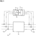
- Figure 1 shows a schematic representation of a measuring system 10, with which a diagnostic variable for specifying an aging condition of electrical equipment 11, for example a transformer, is to be determined in an electrical power supply network (not shown).
- a diagnostic variable for specifying an aging condition of electrical equipment 11 for example a transformer
- two measuring points 12a and 12b are provided, at which signals of electrical measured variables, for example currents and / or voltages, are recorded with measuring sensors only indicated schematically, for example current and / or voltage converters.
- the signals are then fed to a measuring device 13 with which the at least one diagnostic variable is determined therefrom.
- the measuring device 13 has a sampling device 14 which is set with a sampling clock, e.g. with a sampling rate of 1 million samples per second, and samples the signals while obtaining measured values. Specifically, the signal of the at least one measured variable originating from the first measuring point 12a is sampled while obtaining first measured values, while the signal 12b originating from the second measuring point 12b of the at least one measured variable is sampled while obtaining second measured values.
- a sampling clock e.g. with a sampling rate of 1 million samples per second
- the scanning is time-controlled by a timer 15 which transmits a start signal to the scanning device 14 at a predetermined point in time and causes it to scan the signals from the two measuring points 12a, 12b.
- the sampling is carried out during a predetermined measurement period.
- the measurement duration can be set either in the scanning device or in the timer 15. In the latter case, the timer 15 also transmits a stop signal to the scanning device 14 in order to end the acquisition of the first and second measured values.
- the detection is then carried out again at a subsequent predetermined point in time. For example, it can be set in this way that the first and second measured values are to be recorded every 24 hours for a measurement period of 2 seconds. Other settings are also possible.
- sampling times and the measurement duration can e.g. can be specified as a setting value during a configuration of the measuring device 13.
- the measuring points 12a and 12b are arranged in spatial proximity to one another on a local operating means.
- the measuring point 12a can be arranged at the inlet of the equipment 11 and the measuring point 12b at the outlet of the equipment.
- the diagnostic variable can be, for example, a loss factor or a characteristic impedance of the system equivalent circuit diagram of the equipment.
- the aging of the equipment can be determined particularly well using a loss factor.
- other diagnostic variables e.g. complex impedances can be determined or other variables can be derived from it.
- a threshold value can be established for the diagnostic variable, after which a critical aging condition of the equipment is determined when it is reached.
- threshold values can also be defined in order to be able to determine different gradations of the aging condition.
- the diagnostic variable is determined in the exemplary embodiment according to FIG Figure 1 in the measuring device 13 itself.
- the measuring device 13 has an evaluation device 16 which determines the diagnostic variable using the first and second measured values.
- the measured variables on which the measured values are based can be, for example, current, voltage and / or phase angles.
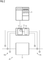
- Figure 2 shows another embodiment of a measuring system 20 for determining a diagnostic variable on a local operating means 11.
- Figures 1 and 2 Corresponding or comparable components are identified by the same reference symbols.
- the main difference between the measuring system 20 and the measuring system 10 of FIG Figure 1 consists in that the evaluation device is not provided in the measuring device 13 itself, but is designed as a central computer system 21. This can be designed in the form of a control center, a station control computer or also a cloud computer system and determine the diagnostic variable. For this purpose, the first and second measured values from the measuring device 13 are fed to the central computer system 21.
- the further functioning of the measuring system 20 corresponds to that of the measuring system 10.
- a diagnostic method can be carried out in which local measuring devices 13 alone or in conjunction with a central computer system 21 can obtain statements about the state of aging of electrical equipment 11 online, that is, during operation of equipment 11.
- the measuring device 13 and possibly the central computer system 21 are designed in such a way that they can also be used in secondary distribution networks in which the condition monitoring of electrical equipment 11 is not possible today for reasons of cost.
- the proposed method is based on a measurement of the loss factor of the electrical equipment 11.
- the measuring device 11 detects signals of measured variables, for example multi-phase currents and voltages at the electrical input or output of the electrical operating means 11 at a very high sampling rate, for example 1 million samples per second.
- the measuring device 13 is designed so that it receives the measurements on the input side as well as on the output side.
- the measuring device 13 comprises a timer 15 which is e.g. can be an inexpensive radio clock module, whose time synchronization can take place, for example, on the basis of the DCF77 signal, which is broadcast via long wave.
- a timer 15 which is e.g. can be an inexpensive radio clock module, whose time synchronization can take place, for example, on the basis of the DCF77 signal, which is broadcast via long wave.
- Such an inexpensive timer is typically not accurate enough for use in power automation systems.
- the use proposed here can make it possible to use such a timer.
- the measuring device 13 scans e.g. the signals from the connected current and voltage sensors, obtaining current and voltage values, and first of all saves them in an internal memory 17.
- the evaluation of the measurements can in principle take place in the measuring device 13 itself ( Figure 1 ).
- the specific parameters of the equipment for example with regard to the insulation medium, for example in the form of a loss factor or a characteristic impedance of the system equivalent circuit diagram of the equipment, are determined from the measured values that belong together over time.
- the loss factors or characteristic impedances of the observed equipment 11 are calculated and the parameters of an associated system equivalent circuit diagram are thus determined.
- the equipment In the case of a transformer as equipment, the equipment consists of the actual transformer and associated bushings, for example. By further processing the loss factors or characteristic impedances, the losses that arise in each of the bushings and in the transformer insulation itself are calculated.
- measurements at different loads e.g. provide an impedance or loss factor temperature spectrum, the evaluation of which shows the condition of the oil or the insulation paper.
- FIG. 30 shows a measuring system 30 which is used to determine a diagnostic variable on a spatially distributed operating means 31.
- a spatially distributed resource it can be, for example, a cable or an overhead line.
- the measuring points 12a and 12b arranged at the input and output of the operating means 31 are therefore at a comparatively large distance from one another, so that the detection of the signals of the measured variables with a single measuring device would not be practical and would also be subject to measurement errors.
- the detection of the signals of the measured variables takes place accordingly with two measuring devices 13a and 13b, which are each arranged in spatial proximity to the respective measuring point 12a, 12b.
- the first measuring device 13a records first measured values at the first measuring point 12a
- the second measuring device 13b records second measured values at the second measuring point 12a.
- Each of the measuring devices 13a, 13b is corresponding to Figure 1 explained measuring device 13 formed.
- a subsequent time synchronization takes place by means of a synchronization device, which can be part of the evaluation device, for example, with which such measured value pairs are determined, their measured values have been recorded at the same time.
- the diagnostic variable is determined in one of the measuring devices 13a, 13b or in both measuring devices 13a, 13b.
- the measured values are transmitted between the measuring devices 13a, 13b via a communication connection 32, which can be wireless or wired, and the subsequent synchronization is carried out.
- the diagnostic variable is then determined with the measured value pairs found.
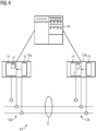
- Figure 4 shows another embodiment of a measuring system for determining a diagnostic variable on a distributed operating means 31
- Figures 3 and 4th Corresponding or comparable components are again identified by the same reference symbols.
- the main difference of the measuring system 40 of the Figure 4 of the measuring system 30 of Figure 3 consists in that the evaluation device is not provided in one or both measuring devices 13a, 13b itself, but as in the exemplary embodiment according to FIG Figure 2 is designed as a central computer system 41.
- This can be designed in the form of a control center, a station control computer or also a cloud computer system and determine the diagnostic variable.
- the first and second measured values from the measuring devices 13a, 13b are fed to the central computer system 41.
- the further functioning of the measuring system 40 corresponds to that of the measuring system 30.
- a diagnostic method can be carried out in which spatially distributed measuring devices 13a, 13b alone or in conjunction with a central computer system 41 can obtain information about the aging status of electrical equipment 31 online, ie during operation of equipment 31.
- the measuring devices 13a, 13b transmit their measured values either to one another or to the central computer system 41.
- the diagnostic variable for example the loss factor
- the readings must be the same Time have been recorded, so be time-synchronous within the framework of a very high time accuracy.
- a time measurement window is parameterized for the measuring devices 13a, 13b, within which the two measuring devices 13a, 13b receive the measured values, e.g. current and voltage values , scan. This is done by specifying a time and a measurement duration, e.g. daily from 12:00:00 to 12:00:02 (hh: mm: ss).
- the timers in both measuring devices 13a, 13b generally have a time offset which is caused by the inaccuracy of their time measurement. This means that the courses of the first and second measured values are not recorded synchronously with one another.
- These gradients are in Figure 5 shown by way of example for first and second measured current values I 1 and I 2 . It is important that the measurement duration is chosen so that the measurement windows of the two measurement devices 13a, 13b overlap at least in one partial area.
- the first derivative is formed from the respective course of the first and second measured values, ie the gradient of the measured value from one sampling interval to the next.
- the pairs of measured values that were recorded at the time of the greatest gradient are transmitted to the evaluation device. In Figure 5 these pairs of measured values are available at times t 1 and t 3 as well as t 2 and t 4 .
- Figure 6 shows a schematic representation of an equivalent circuit diagram of equipment with flowing current I, applied voltage U, as well as capacitive (Ic, C) and ohmic ((IR, R) components.
- the loss factor shows Figure 7 an example of a diagram from which the loss factor can be determined as the tangent of the loss angle ⁇ .
- the in Figure 7 Determine the current phasor shown in relation to the voltage phasor and thus the loss angle ⁇ .
- the aging status of the equipment is then determined.
- the evaluation device provided in a measuring device or the central computer system holds a collection of aging models (e.g. resource-specific threshold values of the diagnostic variable), which are used to draw conclusions from the determined diagnostic variables or the temporal course of the diagnostic variables on the remaining service life of the operating resources, taking into account the load to be expected.
- the aging condition of electrical equipment can thus be continuously monitored. No complex measures for time synchronization are necessary in the measuring devices. Only small amounts of data are exchanged between the measuring devices or a measuring device and a central computer system. As an option, the condition of bushings, oil and paper insulation can be determined at the same time for certain equipment (e.g. transformers).
Description
Die Erfindung betrifft ein Verfahren zum Ermitteln zumindest einer Diagnosegröße, die einen Alterungszustand eines Betriebsmittels in einem elektrischen Energieversorgungsnetz angibt, bei dem an einer ersten Messstelle des Betriebsmittels erste Messwerte zumindest einer Messgröße erfasst werden, an einer zweiten Messstelle des Betriebsmittels zweite Messwerte der zumindest einen Messgröße erfasst werden, und unter Verwendung jeweils gleichzeitig erfasster erster und zweiter Messwerte die zumindest eine Diagnosegröße ermittelt wird.The invention relates to a method for determining at least one diagnostic variable that indicates an aging condition of equipment in an electrical power supply network, in which first measured values of at least one measured variable are recorded at a first measurement point of the equipment, and second measured values of the at least one measured variable at a second measurement point of the equipment are detected, and using first and second measured values recorded simultaneously in each case, the at least one diagnostic variable is determined.
Elektrische Betriebsmittel in Energieversorgungsnetzen, wie beispielsweise Transformatoren, Kabel oder Leitungen, sind durch elektrische Belastungen (z.B. hohe Spannungen und Ströme, Fehlerzustände) im Betrieb aber auch durch äußere Einflüsse (wie mechanische Belastungen, Temperaturschwankungen, extreme Temperaturen, Sonneneinstrahlung, Feuchtigkeit, Frost und ähnliche Einflüsse) einem beständigen Alterungsprozess unterworfen und müssen zur Vorsorge regelmäßig überprüft, gewartet und ausgetauscht werden, um den ordnungsgemäßen Betrieb des Energieversorgungsnetzes zu gewährleisten.Electrical equipment in energy supply networks, such as transformers, cables or lines, are exposed to electrical loads (e.g. high voltages and currents, fault conditions) during operation, but also to external influences (such as mechanical loads, temperature fluctuations, extreme temperatures, solar radiation, moisture, frost and the like Influences) are subject to a constant aging process and must be regularly checked, serviced and replaced as a precaution in order to guarantee the proper operation of the energy supply network.
In heutigen elektrischen Energieversorgungsnetzen ist die automatische Überwachung des Alterungszustandes eines elektrischen Betriebsmittels sehr aufwendig und teuer. Aus diesem Grund werden im Allgemeinen nur sehr große und/oder sehr hochwertige Betriebsmittel, wie zum Beispiel Transformatoren in Hochspannungsnetzen, mit entsprechenden Sensoren und Auswertesystemen ausgerüstet, die in Echtzeit eine Überwachung und Diagnose des Alterungszustandes erlauben. Häufig wird dabei auch nicht das gesamte Betriebsmittel betrachtet, sondern es werden nur ausgewählte Komponenten überwacht.In today's electrical energy supply networks, the automatic monitoring of the state of aging of electrical equipment is very complex and expensive. For this reason, generally only very large and / or very high-quality equipment, such as transformers in high-voltage networks, are equipped with appropriate sensors and evaluation systems that allow real-time monitoring and diagnosis of the aging condition. Often the entire equipment is not considered, but only selected components are monitored.
Während in Hochspannungs-Übertragungsnetzen eine automatische Überwachung und Diagnose von Betriebsmitteln daher noch vergleichswiese häufig stattfindet, ist in Verteilnetzen der Mittel- und Niederspannungsebene eine online-Überwachung, also eine Überwachung während des laufenden Betriebs, dagegen aus Kostengründen eher unüblich. Wenige ausgesuchte Betriebsmittel werden dort mit Hilfe von speziellen Diagnosesystemen untersucht, wobei sie für die Untersuchung aus dem Betrieb genommen werden müssen. Für die diagnostische Zwecke wurden unterschiedliche Methoden entwickelt, die für spezifische Betriebsmittel jeweils am besten geeignet sind. Diese basieren meistens auf offline durchgeführte Messungen, d.h. im Feld befindliche und zu diagnostizierende Betriebsmittel werden hierfür zuerst aus dem Betrieb genommen.While automatic monitoring and diagnosis of equipment is still comparatively common in high-voltage transmission networks, online monitoring, i.e. monitoring during ongoing operation, is rather uncommon for reasons of cost in distribution networks of the medium and low-voltage level. A few selected resources are examined there with the help of special diagnostic systems, whereby they have to be taken out of operation for the examination. Different methods have been developed for diagnostic purposes, each of which is best suited for specific equipment. These are mostly based on measurements carried out offline, i.e. Equipment located in the field and to be diagnosed is first taken out of operation.
Die wenigen online durchführbaren diagnostischen Methoden sind zudem spezifisch für die Betriebsmittel. Meistens trifft man auf Teilentladungsmessungen, die Schwachstellen in den Isolationsmedien identifizieren sollen. Ein Beispiel einer Methode zur Bestimmung des Alterungszustandes von Betriebsmitteln wie Transformatoren oder Generatoren ist aus der
Die Messung von Teilentladungen kann auch zur Überwachung von Kabeln eingesetzt werden. Eine weitere Möglichkeit für eine online durchführbare Diagnose besteht in einer Verlustfaktormessung. Beispielhaft sei die
Es wäre jedoch wünschenswert, auch in Verteilnetzen den Alterungszustand der Betriebsmittel genauer zu kennen, um Wartungs- und Instandhaltungsmaßnahmen optimal planen zu können. Zusätzlich wäre es vorteilhaft, diese Zustände ohne Unterbrechung des Betriebes ermitteln zu können.However, it would be desirable to know the aging condition of the equipment in distribution networks in order to be able to optimally plan maintenance and repair measures. In addition, it would be advantageous to be able to determine these states without interrupting operation.
Aufgabe der Erfindung ist damit, eine ohne Unterbrechung des Betriebsablaufs eines Betriebsmittels durchführbare und vergleichsweise einfache Ermittlung eines Alterungszustands des Betriebsmittels anzugeben.The object of the invention is therefore to provide a comparatively simple determination of an aging condition of the operating medium that can be carried out without interrupting the operational sequence of an operating medium.
Zur Lösung dieser Aufgabe wird ein Verfahren der eingangsgenannten Art vorgeschlagen, bei dem die Erfassung der ersten und zweiten Messwerte zeitgesteuert in der Weise erfolgt, dass ein Signal der zumindest einen Messgröße mit einer vorgegebenen Abtastrate zu festgelegten Zeitpunkten und während einer festgelegten Messdauer unter Erzeugung von zeitlichen Verläufen der ersten und zweiten Messwerte abgetastet werden.To solve this problem, a method of the type mentioned is proposed in which the acquisition of the first and second measured values takes place in a time-controlled manner in such a way that a signal of the at least one measured variable with a predetermined sampling rate at defined times and during a defined measurement period with generation of time Course of the first and second measured values are scanned.
Auf diese Weise kann vorteilhaft erreicht werden, dass die Erfassung der für die Berechnung der Diagnosegröße erforderlichen Messwerte keine aufwendige Synchronisation stattfinden muss. Vielmehr ist bereits im Vorfeld festgelegt, zu welchen Zeitpunkten eine Erfassung der Messwerte startet und wie lange sie dauert.In this way, it can advantageously be achieved that the acquisition of the measured values required for calculating the diagnostic variable does not have to take place in a complex synchronization. Rather, it is already determined in advance at which points in time a recording of the measured values starts and how long it lasts.
Die vorgegebene Abtastrate sollte hierbei für die Ermittlung der zumindest einen Diagnosegröße angemessen sein. Beispielsweise kann sie 1 Million Abtastwerte pro Sekunde betragen. Andere Abtastraten sind jedoch ebenso möglich. Hierdurch kann eine Erfassung der Messwerte mit einer für die Berechnung der Diagnosegröße optimalen zeitlichen Auflösung erfolgen.The specified sampling rate should be appropriate for determining the at least one diagnostic variable. For example, it can be 1 million samples per second. However, other sampling rates are also possible. As a result, the measured values can be recorded with a time resolution that is optimal for calculating the diagnostic variable.
Gemäß einer vorteilhaften Ausführungsform des erfindungsgemäßen Verfahrens ist zudem vorgesehen, dass - die festgelegten Zeitpunkte und/oder die festgelegte Messdauer durch eine Konfiguration vorgegeben wird.According to an advantageous embodiment of the method according to the invention it is also provided that - the specified Times and / or the specified measurement duration is specified by a configuration.
Hierbei kann beispielsweise eine bei der Inbetriebnahme einer Messeinrichtung erforderliche Konfiguration durch Eingabe entsprechender Einstellwerte hinsichtlich der zu verwendenden Zeitpunkte und Messdauern spezifisch angepasst werden.Here, for example, a configuration required when a measuring device is put into operation can be specifically adapted by entering appropriate setting values with regard to the times and measuring periods to be used.
Gemäß einer weiteren vorteilhaften Ausführungsform des erfindungsgemäßen Verfahrens wird vorgeschlagen, dass als Messgröße ein elektrischer Strom, eine elektrische Spannung und/oder ein Phasenwinkel an der ersten und zweiten Messstelle des Betriebsmittels verwendet werden.According to a further advantageous embodiment of the method according to the invention, it is proposed that an electric current, an electric voltage and / or a phase angle at the first and second measuring point of the operating means are used as the measured variable.
Auf diese Weise kann durch Erfassung in elektrischen Energieversorgungsnetzen üblicher Messgrößen eine Diagnosegröße gebildet werden, die einen Aufschluss auf den Alterungszustand des Betriebsmittels erlaubt.In this way, a diagnostic variable can be formed by recording common measured variables in electrical energy supply networks, which allows information on the aging status of the equipment.
Konkret kann hierbei vorgesehen sein, dass - die zumindest eine Diagnosegröße in Form eines Verlustfaktors des Betriebsmittels oder einer charakteristischen Impedanz eines Systemersatzschaltbildes des Betriebsmittels ermittelt wird.Specifically, it can be provided here that the at least one diagnostic variable is determined in the form of a loss factor of the equipment or a characteristic impedance of a system equivalent circuit diagram of the equipment.
Der Verlustfaktor (englisch "dissipation factor") beschreibt quasi die elektrischen Verluste innerhalb des Betriebsmittels, die beispielsweise durch Umwandlung elektrischer Energie durch Dissipation in Wärme erfolgt. Der Verlustfaktor ermittelt sich als Tangens des Verlustwinkels δ zwischen einer komplexen elektrischen Größe (z.B. Strom) und ihrem Imaginärteil. Somit kann durch Angabe des Verlustfaktors, und insbesondere durch Beobachtung einer Veränderung des Verlustfaktors über die Zeit, eine geeignete Angabe über den Alterungszustand eines Betriebsmittels gegeben werden.The loss factor (English "dissipation factor") describes, so to speak, the electrical losses within the equipment, which occurs, for example, by converting electrical energy through dissipation into heat. The loss factor is determined as the tangent of the loss angle δ between a complex electrical quantity (e.g. current) and its imaginary part. Thus, by specifying the loss factor, and in particular by observing a change in the loss factor over time, suitable information about the state of aging of an item of equipment can be given.
Eine charakteristische Impedanz ist diejenige Impedanz, die das entsprechende Ersatzschaltbild (Systemersatzschaltbild) des Betriebsmittels angibt und insbesondere das Betriebsmittel und sein Isolationssystem beschreibt.A characteristic impedance is that impedance which the corresponding equivalent circuit diagram (system equivalent circuit diagram) of the equipment and in particular describes the equipment and its insulation system.
Gemäß einer möglichen Ausführungsform des erfindungsgemäßen Verfahrens ist vorgesehen, dass die erste und die zweite Messstelle des Betriebsmittels in räumlicher Nähe zueinander angeordnet sind, und die ersten und zweiten Messwerte mittels einer einzelnen Messeinrichtung erfasst werden, die in räumlicher Nähe zu den Messstellen angeordnet ist.According to a possible embodiment of the method according to the invention, it is provided that the first and the second measuring point of the equipment are arranged in spatial proximity to one another, and the first and second measured values are recorded by means of a single measuring device that is arranged in spatial proximity to the measuring points.
Unter "in räumlicher Näher zueinander angeordnet" soll hierbei eine Anordnung der Messstellen angesehen werden, die es erlaubt, mit vertretbarem Aufwand hinsichtlich elektrischer Verkabelung die jeweiligen Messwerte mit einer einzigen Messeinrichtung zu erfassen. Üblicherweise sind die Messstellen am Eingang und Ausgang eines lokalen Betriebsmittels, wie beispielsweise eines Transformators, eines Motors oder eines Generators, in räumlicher Nähe zueinander angeordnet, da es ohne großen Aufwand möglich ist, die an diesen Messstellen aufgenommenen Signale der elektrischen Messgrößen mittels einer einzigen Messeinrichtung, die über Verkabelung mit den Messsensoren der jeweiligen Messstelle verbunden ist, zu erfassen. In diesem Fall wird die Erfassung der über die Verkabelung an die Messeinrichtung herangeführten Signale der Messgrößen durch zeitgesteuerte Abtastung der Signale unter Bildung der Messwerte in der Messeinrichtung durchgeführt."Arranged spatially closer to one another" is to be regarded as an arrangement of the measuring points which allows the respective measured values to be recorded with a single measuring device with reasonable expenditure in terms of electrical cabling. The measuring points at the input and output of local equipment, such as a transformer, a motor or a generator, are usually arranged in close proximity to one another, since it is possible without great effort to measure the electrical measurement signals recorded at these measuring points using a single measuring device that is connected to the measuring sensors of the respective measuring point via cabling. In this case, the detection of the signals of the measured variables brought to the measuring device via the cabling is carried out by time-controlled sampling of the signals while forming the measured values in the measuring device.
Eine andere Ausführungsform des erfindungsgemäßen Verfahrens sieht vor, dass die erste und die zweite Messstelle des Betriebsmittels räumlich voneinander entfernt angeordnet sind, und die ersten Messwerte mittels einer ersten Messeinrichtung und die zweiten Messwerte mittels einer zweiten Messeinrichtung erfasst werden.Another embodiment of the method according to the invention provides that the first and second measuring points of the operating means are spatially separated from one another, and the first measured values are recorded by means of a first measuring device and the second measured values are recorded by means of a second measuring device.
Bei dieser Ausführungsform liegt im Unterschied zur vorigen Ausführungsform kein lokales Betriebsmittel vor, vielmehr wird die Messung an einem räumlich verteilten Betriebsmittel, wie z.B. einem unterirdisch verlegten Kabel oder eine überirdisch verlaufenden Freileitung, durchgeführt, bei dem die Messstellen so weit auseinanderliegen, dass eine Erfassung der Signale der Messgrößen mit einer einzigen Messeinrichtung nicht nur unpraktikabel, sondern auch mit Messfehlern behaftet ist, die durch die Übertragung der Signale über lange Distanzen entstehen. So kann es bei Kabeln in Verteilnetzen durchaus vorkommen, dass die Messstellen in einer Entfernung von einigen Kilometern zueinander liegen. Bei einer solchen räumlich auseinander liegenden Anordnung der Messstellen werden die Messwerte folglich mit zwei Messeinrichtungen erfasst.In this embodiment, in contrast to the previous embodiment, there is no local equipment, rather the measurement is carried out on a spatially distributed equipment, such as an underground cable or an overhead power line, in which the measuring points are so far apart that recording the signals of the measured variables with a single measuring device is not only impractical, but also subject to measurement errors caused by the transmission of the signals arise over long distances. In the case of cables in distribution networks, for example, the measuring points may well be a few kilometers apart. With such a spatially spaced arrangement of the measuring points, the measured values are consequently recorded with two measuring devices.
In diesem Zusammenhang ist gemäß einer vorteilhaften Ausführungsform des erfindungsgemäßen Verfahrens vorgesehen, dass die erste und die zweite Messeinrichtung jeweils einen Zeitgeber umfassen, der die zeitgesteuerte Erfassung der Messwerte steuert.In this context, according to an advantageous embodiment of the method according to the invention, it is provided that the first and the second measuring device each include a timer which controls the time-controlled acquisition of the measured values.
Hierdurch kann erreicht werden, dass eine Erfassung von zeitlich zueinander gehörenden Messwerten stattfindet, aus denen sich die Diagnosegröße ermitteln lässt. Jede der beiden Messeinrichtungen führt hierbei über ihren Zeitgeber gesteuert die Erfassung der Messwerte durch.In this way it can be achieved that measured values belonging to one another over time are recorded, from which the diagnostic variable can be determined. Each of the two measuring devices carries out the acquisition of the measured values controlled by its timer.
Konkret kann in diesem Zusammenhang vorgesehen sein, dass der jeweilige Zeitgeber mittels eines Synchronisiersignals auf eine externe Zeitquelle abgestimmt wird.Specifically, it can be provided in this context that the respective timer is tuned to an external time source by means of a synchronization signal.
Auf diese Weise kann nämlich erreicht werden, dass die Zeitgeber in den Messeinrichtungen zeitlich möglichst gut aufeinander abstimmt sind, so dass eine Erfassung zeitlich zueinander gehörender Messwerte vereinfacht wird.In this way it can namely be achieved that the timers in the measuring devices are time-coordinated with one another as well as possible, so that the acquisition of measured values that belong to one another over time is simplified.
Außerdem sieht eine weitere vorteilhafte Ausführungsform in diesem Zusammenhang vor, dass die festgelegten Zeitpunkte und Messdauern zur Erfassung der Messwerte der ersten und der zweiten Messwerte zeitlich derart festgelegt werden, dass die zeitgesteuerte Erfassung der Messwerte zumindest während eines Überlappungs-Zeitbereichs in den beiden Messeinrichtungen gleichzeitig erfolgt.In addition, a further advantageous embodiment provides in this context that the specified times and measurement periods for recording the measurement values of the first and the second measured values are set in time in such a way that the time-controlled acquisition of the measured values takes place simultaneously in the two measuring devices at least during an overlapping time range.
Hierbei findet vorteilhaft die zeitgesteuerte Erfassung der Messwerte derart statt, dass während der von der jeweiligen Messeinrichtung erfassten Messwerte immer zumindest einige Messwerte an beiden Messstellen gleichzeitig zueinander erfasst werden. Die Zeitdauern, während denen an den beiden Messstellen die Messwerte erfasst werden, können somit durchaus zu unterschiedlichen absoluten Zeitpunkten beginnen und unterschiedliche Längen zeitliche aufweisen, es ist für die Auswertung ausreichend, wenn sie lediglich einen Überlappungsbereich aufweisen, innerhalb dessen an beiden Messstellen - zeitlich absolut gesehen - gleichzeitig Messwerte erfasst werden.In this case, the time-controlled acquisition of the measured values takes place in such a way that during the measured values acquired by the respective measuring device, at least some measured values are always acquired simultaneously at both measuring points. The periods of time during which the measured values are recorded at the two measuring points can therefore begin at different absolute times and have different temporal lengths; it is sufficient for the evaluation if they only have an overlap area within which at both measuring points - absolute in time seen - measured values are recorded at the same time.
In diesem Zusammenhang kann konkret beispielsweise vorgesehen sein, dass die Verläufe der ersten und zweiten Messwerte abgespeichert und durch nachträgliche Synchronisierung aus den Verläufen jeweils gleichzeitig erfasste Messwertpaare der zumindest einen Messgröße ermittelt werden.In this context, it can specifically be provided, for example, that the curves of the first and second measured values are stored and, by subsequent synchronization, simultaneously recorded pairs of measured values of the at least one measured variable are determined from the curves.
Diese Ausführungsform besitzt den Vorteil, dass auch bei nicht hochgenau miteinander synchronisierten Zeitgebern des Messeinrichtungen aus den abgespeicherten Verläufen diejenigen Messwerte ermittelt werden können, die tatsächlich zu - absolut gesehen - gleichen Messzeitpunkten erfasst worden sind. Dadurch dass die Synchronisation nachträglich anhand der abgespeicherten Verläufe durchgeführt wird und nicht durch aufwendige Maßnahmen hinsichtlich der Zeitgeber der Messeinrichtungen im Voraus vorgesehen sein muss, ist es möglich, verhältnismäßig günstige - dadurch allerdings auch ungenauere - Zeitgeber zu verwenden. Ein Beispiel eines kostengünstigen Zeitgebers, der in einer erfindungsgemäßen Messeinrichtung verwendet werden kann, ist ein im Umfeld von Funkuhren verwendeter Zeitgeber, dessen Uhrzeit mit einem DCF77-Signal, das per Langwelle ausgestrahlt wird, eingestellt wird. Die Genauigkeit eines solchen Zeitgebers liegt etwa bei 100 ms, was für hochgenaue Messungen im Umfeld von Energieversorgungsnetzen an sich zu ungenau wäre. Durch die nachträgliche Synchronisierung lassen sich jedoch Unterschide der Uhrzeiten beider Zeitgeber vergleichsweise einfach ausgleichen.This embodiment has the advantage that, even if the measuring device's timers are not synchronized with one another with high precision, those measured values can be determined from the stored profiles that were actually recorded at - in absolute terms - the same measuring times. The fact that the synchronization is carried out later on the basis of the stored profiles and does not have to be provided in advance by means of complex measures with regard to the timers of the measuring devices makes it possible to use relatively cheap - but also less accurate - timers. An example of an inexpensive timer that can be used in a measuring device according to the invention is one in the area of radio clocks The timer used whose time is set with a DCF77 signal that is broadcast via long wave. The accuracy of such a timer is around 100 ms, which in itself would be too imprecise for high-precision measurements in the vicinity of energy supply networks. However, due to the subsequent synchronization, differences in the times of the two timers can be compensated comparatively easily.
In diesem Zusammenhang kann beispielsweise vorgesehen sein, dass zur nachträglichen Synchronisierung aus den Verläufen der ersten und zweiten Messwerte jeweils die erste zeitliche Ableitung gebildet wird, in jedem Verlauf der abgeleiteten Messwerte das Maximum und der zugehörige Zeitpunkt, zu dem das Maximum in dem jeweiligen Verlauf auftritt, ermittelt werden, und diejenigen Messwerte, die zum Zeitpunkt des jeweiligen Maximums erfasst worden sind, als gleichzeitig erfasstes Messwertpaar verwendet werden.In this context, it can be provided, for example, that for subsequent synchronization the first time derivative is formed from the curves of the first and second measured values, in each curve of the derived measured values the maximum and the associated time at which the maximum occurs in the respective curve , are determined, and those measured values that were recorded at the time of the respective maximum are used as a simultaneously recorded pair of measured values.
Auf diese Weise kann mit einfachen mathematischen Mitteln, nämlich lediglich durch Bildung der ersten Ableitung des Verlaufs, eine nachträgliche zeitliche Synchronisation durchgeführt werden. Hierbei wird der Effekt ausgenutzt, dass durch äußere Einflüsse, z.B. durch ein Rauschen auf den zu messenden Signalen der Messgrößen, auf die Amplituden der Signale ein Muster aufgeprägt wird, das sich gleichzeitig an beiden Messstellen erkennen lässt. Werden durch Gradientenbildung diese Effekte kenntlich gemacht, so können sie zur Synchronisation der Messwerte herangezogen werden, indem diejenigen Messwerte der Verläufe, die zum jeweiligen Zeitpunkt des größten Gradienten erfasst worden sind, als gleichzeitig erfasst angenommen werden.In this way, a subsequent time synchronization can be carried out using simple mathematical means, namely only by forming the first derivative of the curve. Here, the effect is used that external influences, e.g. Due to a noise on the measured variable signals to be measured, a pattern is impressed on the amplitudes of the signals that can be recognized at both measuring points at the same time. If these effects are identified by forming gradients, they can be used to synchronize the measured values, in that those measured values of the curves that were recorded at the respective point in time of the greatest gradient are assumed to be recorded simultaneously.
Eine weitere vorteilhafte Ausführungsform des erfindungsgemäßen Verfahrens sieht hierbei vor, dass mindestens dasjenige Messwertpaar, das zum Zeitpunkt des jeweiligen Maximums erfasst worden ist, an eine Auswertungseinrichtung übermittelt werden, und mit der Auswertungseinrichtung die Diagnosegröße ermittelt wird.A further advantageous embodiment of the method according to the invention provides that at least that pair of measured values that was recorded at the time of the respective maximum is transmitted to an evaluation device and the diagnostic variable is determined with the evaluation device.
Die Auswertungseinrichtung kann hierbei eine separate Einrichtung oder Bestandteil einer der Messeinrichtungen sein. Die Diagnosegröße kann hierbei auf Grundlage eines Messwertpaares oder mehrerer Messwertpaare ermittelt werden. Dadurch dass zumindest das durch die nachträgliche Synchronisierung ermittelte Messwertpaar als gleichzeitig erfasst erkannt worden ist, können auch die umliegenden Messwerte entsprechend zeitlich einander zugeordnet werden.The evaluation device can be a separate device or a component of one of the measuring devices. The diagnostic variable can be determined on the basis of a pair of measured values or several pairs of measured values. Because at least the pair of measured values determined by the subsequent synchronization has been recognized as being recorded at the same time, the surrounding measured values can also be assigned to one another in time.
Die oben genannte Aufgabe wird auch durch eine Messeinrichtung zum Erfassen von Messwerten in einem elektrischen Energieversorgungsnetz gelöst, die eine Abtasteinrichtung zur Abtastung eines Signals zumindest einer elektrischen Messgröße unter Verwendung einer vorgegebenen Abtastrate aufweist.The above-mentioned object is also achieved by a measuring device for acquiring measured values in an electrical power supply network, which has a sampling device for sampling a signal of at least one electrical measured variable using a predetermined sampling rate.
Erfindungsgemäß sind ein Zeitgeber, der dazu eingerichtet ist, die Erfassung der Messwerte zeitgesteuert in der Weise durchzuführen, dass das Signal der Messgröße mit einer vorgegebenen Abtastrate zu festgelegten Zeitpunkten und während einer festgelegten Messdauer unter Erzeugung eines zeitlichen Verlaufs der Messwerte abgetastet werden, sowie eine Speichereinrichtung zum Abspeichern der Verläufe der Messwerte vorgesehen.According to the invention, a timer is set up to record the measured values in a time-controlled manner in such a way that the signal of the measured variable is sampled at a predetermined sampling rate at defined times and during a defined measurement period, generating a time profile of the measured values, and a memory device intended for storing the progression of the measured values.
Hinsichtlich der erfindungsgemäßen Messeinrichtung gelten alle zu dem erfindungsgemäßen Verfahren voranstehend und nachfolgend gemachten Ausführungen und umgekehrt in entsprechender Weise, insbesondere ist die erfindungsgemäße Messeinrichtung zur Durchführung des erfindungsgemäßen Verfahrens in jeder beliebigen Ausführungsform oder einer Kombination beliebiger Ausführungsformen eingerichtet. Auch hinsichtlich der Vorteile der erfindungsgemäßen Messeinrichtung wird auf die zu dem erfindungsgemäßen Verfahren beschriebenen Vorteile verwiesen.With regard to the measuring device according to the invention, all statements made above and below regarding the method according to the invention apply and vice versa in a corresponding manner, in particular the measuring device according to the invention is set up to carry out the method according to the invention in any embodiment or a combination of any embodiments. With regard to the advantages of the measuring device according to the invention, reference is made to the advantages described for the method according to the invention.
Außerdem wird die oben genannte Aufgabe durch ein Messsystem zum Ermitteln zumindest einer Diagnosegröße mit zumindest zwei nach Anspruch 13 ausgebildeten Messeinrichtungen gelöst, das eine Synchronisiereinrichtung aufweist, die dazu ausgebildet ist, durch nachträgliche Synchronisierung aus den Verläufen der Messwerte jeweils gleichzeitig in den Messeinrichtungen erfasste Messwertpaare zu ermitteln, indem sie in jedem Verlauf der Messwerte jeweils die erste zeitliche Ableitung bildet, in jedem Verlauf der abgeleiteten Messwerte das Maximum ermittelt und diejenigen Messwerte, die zum Zeitpunkt des jeweiligen Maximums erfasst worden sind, als gleichzeitig erfasstes Messwertpaar verwendet, und das eine Analyseeinrichtung aufweist, die dazu eingerichtet ist, die zumindest eine Diagnosegröße zumindest aus dem gleichzeitig erfassten Messwertpaar zu ermitteln.In addition, the above-mentioned object is achieved by a measuring system for determining at least one diagnostic variable with at least two measuring devices designed according to
Hinsichtlich des erfindungsgemäßen Messsystems gelten alle zu dem erfindungsgemäßen Verfahren voranstehend und nachfolgend gemachten Ausführungen und umgekehrt in entsprechender Weise, insbesondere ist die erfindungsgemäße Messsystem zur Durchführung des erfindungsgemäßen Verfahrens in jeder beliebigen Ausführungsform oder einer Kombination beliebiger Ausführungsformen eingerichtet. Auch hinsichtlich der Vorteile des erfindungsgemäßen Messsystems wird auf die zu dem erfindungsgemäßen Verfahren beschriebenen Vorteile verwiesen.With regard to the measuring system according to the invention, all statements made above and below about the method according to the invention apply and vice versa in a corresponding manner, in particular the measuring system according to the invention is set up to carry out the method according to the invention in any embodiment or a combination of any embodiments. With regard to the advantages of the measuring system according to the invention, reference is made to the advantages described for the method according to the invention.
Die Erfindung wird nachfolgend anhand eines Ausführungsbeispiels näher erläutert. Die spezifische Ausgestaltung des Ausführungsbeispiels ist für die allgemeine Ausgestaltung des erfindungsgemäßen Verfahrens und der erfindungsgemäßen Einrichtung in keiner Weise einschränkend zu verstehen; vielmehr können einzelne Ausgestaltungsmerkmale des Ausführungsbeispiels in beliebiger Weise frei untereinander und mit den voranstehend beschriebenen Merkmalen kombiniert werden.The invention is explained in more detail below using an exemplary embodiment. The specific configuration of the exemplary embodiment is in no way to be understood as limiting the general configuration of the method according to the invention and the device according to the invention; rather, individual design features of the exemplary embodiment can be freely combined with one another and with the features described above in any desired manner.
Es zeigen
- Figur 1
- ein erstes Ausführungsbeispiel eines Messsystems zur Ermittlung zumindest einer Diagnosegröße, bei dem die Messstellen in räumlicher Nähe zueinander angeordnet sind;
- Figur 2
- ein zweites Ausführungsbeispiel eines Messsystems zur Ermittlung zumindest einer Diagnosegröße, bei dem die Messstellen in räumlicher Nähe zueinander angeordnet sind;
- Figur 3
- ein erstes Ausführungsbeispiel eines Messsystems zur Ermittlung zumindest einer Diagnosegröße, bei dem die Messstellen räumlich voneinander entfernt angeordnet sind;
- Figur 4
- ein zweites Ausführungsbeispiel eines Messsystems zur Ermittlung zumindest einer Diagnosegröße, bei dem die Messstellen räumlich voneinander entfernt angeordnet sind;
Figur 5- Diagramme mit Verläufen von Strommesswerten, die an zwei Messstellen aufgenommen worden sind, zur Erläuterung einer nachträglichen zeitlichen Synchronisation.
- Figur 6
- ein Ersatzschaltbild eines elektrischen Kabels zur Erläuterung des Verlustfaktors; und
- Figur 7
- ein Diagramm zur Erläuterung der Ermittlung eines Verlustfaktors.
- Figure 1
- a first embodiment of a measuring system for determining at least one diagnostic variable, in which the measuring points are arranged in spatial proximity to one another;
- Figure 2
- a second exemplary embodiment of a measuring system for determining at least one diagnostic variable, in which the measuring points are arranged in spatial proximity to one another;
- Figure 3
- a first exemplary embodiment of a measuring system for determining at least one diagnostic variable, in which the measuring points are arranged spatially apart from one another;
- Figure 4
- a second exemplary embodiment of a measuring system for determining at least one diagnostic variable, in which the measuring points are arranged spatially apart from one another;
- Figure 5
- Diagrams showing the progression of measured current values that have been recorded at two measuring points, to explain a subsequent time synchronization.
- Figure 6
- an equivalent circuit diagram of an electrical cable to explain the loss factor; and
- Figure 7
- a diagram to explain the determination of a loss factor.
Die Messeinrichtung 13 weist eine Abtasteinrichtung 14 auf, die mit einem Abtasttakt, z.B. mit einer Abtastrate von 1 Million Abtastwerten (Samples) pro Sekunde, beaufschlagt ist und die Signale unter Gewinnung von Messwerten abtastet. Konkret wird das von der ersten Messstelle 12a stammende Signal der zumindest einen Messgröße unter Gewinnung von ersten Messwerten abgetastet, während das von der zweiten Messstelle 12b stammende Signal 12b der zumindest einen Messgröße unter Gewinnung von zweiten Messwerten abgetastet wird.The measuring
Die Abtastung erfolgt zeitgesteuert durch einen Zeitgeber 15, der zu einem vorbestimmten Zeitpunkt ein Startsignal an die Abtasteinrichtung 14 übermittelt und diese zur Abtastung der Signale der beiden Messstellen 12a, 12b veranlasst. Die Abtastung wird während einer vorbestimmten Messdauer durchgeführt. Die Messdauer kann entweder in der Abtasteinrichtung oder in dem Zeitgeber 15 eingestellt sein. Im letztgenannten Fall übermittelt der Zeitgeber 15 auch ein Stoppsignal an die Abtasteinrichtung 14, um die Erfassung der ersten und zweiten Messwerte zu beenden. Die Erfassung wird daraufhin zu einem folgenden vorbestimmten Zeitpunkt erneut durchgeführt. Beispielsweise kann auf diese Weise eingestellt sein, dass eine Erfassung der ersten und zweiten Messwerte alle 24 Stunden für eine Messdauer von 2 Sekunden stattfinden soll. Andere Einstellungen sind ebenso möglich.The scanning is time-controlled by a
Die Festlegung der Abtastzeitpunkte und der Messdauer kann z.B. während einer Konfiguration der Messeinrichtung 13 als Einstellwert vorgegeben werden.The definition of the sampling times and the measurement duration can e.g. can be specified as a setting value during a configuration of the measuring
Bei der Ausführungsform gemäß
Bei der Diagnosegröße kann es sich beispielsweise um einen Verlustfaktor oder eine charakteristische Impedanz des Systemersatzschaltbildes des Betriebsmittels handeln. Anhand eines Verlustfaktors lässt sich die Alterung des Betriebsmittels besonders gut feststellen. Alternativ können auch andere Diagnosegrößen, z.B. komplexe Impedanzen, ermittelt werden oder weitere Größen daraus abgeleitet werden.The diagnostic variable can be, for example, a loss factor or a characteristic impedance of the system equivalent circuit diagram of the equipment. The aging of the equipment can be determined particularly well using a loss factor. Alternatively, other diagnostic variables, e.g. complex impedances can be determined or other variables can be derived from it.
Insbesondere kann durch Vergleich zeitlich nacheinander ermittelter Diagnosegrößen, z.B. über den Verlauf eines Jahres betrachtet, eine Veränderung der Diagnosegröße und damit eine voranschreitende Alterung des Betriebsmittels erkannt werden. Es kann ein Schwellenwert für die Diagnosegröße festgelegt sein, ab dessen Erreichen ein kritischer Alterungszustand des Betriebsmittels festgestellt wird. Auch können mehrere Schwellenwerte festgelegt sein, um verschiedene Abstufungen des Alterungszustands ermitteln zu können.In particular, by comparing diagnostic variables determined one after the other, e.g. Considered over the course of a year, a change in the diagnostic variable and thus progressive aging of the equipment can be detected. A threshold value can be established for the diagnostic variable, after which a critical aging condition of the equipment is determined when it is reached. Several threshold values can also be defined in order to be able to determine different gradations of the aging condition.
Die Ermittlung der Diagnosegröße findet bei dem Ausführungsbeispiel gemäß
Der wesentliche Unterschied des Messsystems 20 von dem Messsystem 10 der
Die weitere Funktionsweise des Messsystems 20 stimmt mit derjenigen des Messsystems 10 überein.The further functioning of the measuring
Somit kann mit den Messsystemen 10 und 20 der
Die Messeinrichtung 13 und ggf. das zentrale Computersystem 21 werden dabei so gestaltet, dass sie auch in sekundären Verteilnetzen eingesetzt werden können, in denen heute die Zustandsüberwachung von elektrischen Betriebsmitteln 11 aus Kostengründen nicht möglich ist.The measuring
Das vorgeschlagene Verfahren beruht gemäß einer Ausführung auf einer Messung des Verlustfaktors des elektrischen Betriebsmittels 11. Um die hierfür heute üblicherweise erforderliche hochgenaue Zeitsynchronisation und die teure Übertragung von großen Datenmengen zu umgehen, wird das folgende Vorgehen vorgeschlagen:
Die Messeinrichtung 11 erfasst Signale von Messgrößen, z.B. mehrphasige Ströme und Spannungen am elektrischen Eingang bzw. Ausgang des elektrischen Betriebsmittels 11 mit einer sehr hohen Abtastrate, z.B. 1 Million Abtastwerte pro Sekunde. Im Falle von räumlich konzentrierten Betriebsmitteln (z.B. Transformatoren, Generatoren, Motoren, Schaltern) wird die Messeinrichtung 13 so ausgeführt, dass es sowohl die Messungen auf der Eingangsseite als auch auf der Ausgangsseite entgegennimmt.According to one embodiment, the proposed method is based on a measurement of the loss factor of the
The measuring
Die Messeinrichtung 13 umfasst einen Zeitgeber 15, bei dem es sich z.B. um ein preiswertes Funkuhrmodul handeln kann, dessen Zeitsynchronisierung beispielsweise auf Basis des DCF77-Signals, das per Langwelle ausgestrahlt wird, erfolgen kann. Ein solcher kostengünstiger Zeitgeber ist üblicherweise nicht genau genug für eine Anwendung in Energieautomatisierungssystemen. Durch die hier vorgeschlagene Verwendung kann jedoch eine Benutzung eines solchen Zeitgebers ermöglicht werden.The measuring
Zu vorbestimmten Zeitpunkten, die bei der Konfiguration der Messeinrichtung 13 definiert werden, tastet die Messeinrichtung 13 z.B. die Signale der angeschlossenen Strom- und Spannungssensoren unter Gewinnung von Strom- und Spannungswerten ab und legt diese zunächst in einem internen Speicher 17 ab.At predetermined times, which are defined when configuring the measuring
Im Falle von lokal konzentrierten Betriebsmitteln 11 kann die Auswertung der Messungen prinzipiell in der Messeinrichtung 13 selbst erfolgen (
Im Laufe der Betriebsjahre verändern sich die berechneten Verlustfaktoren oder charakteristischen Impedanzen oder deren Anteile (realer bzw. imaginärer Anteil) und deuten dadurch auf einen Alterungsprozess hin.In the course of the years of operation, the calculated loss factors or characteristic impedances or their proportions (real or imaginary proportion) change and thus indicate an aging process.
Im Falle eines Transformators als Betriebsmittel besteht das Betriebsmittel hierbei beispielsweise aus dem eigentlichen Transformator und dazugehörigen Durchführungen. Durch weitere Bearbeitung der Verlustfaktoren oder charakteristischen Impedanzen werden die Verluste, die in jede der Durchführung und in der Transformatorisolation selbst entstehen, berechnet.In the case of a transformer as equipment, the equipment consists of the actual transformer and associated bushings, for example. By further processing the loss factors or characteristic impedances, the losses that arise in each of the bushings and in the transformer insulation itself are calculated.
Weiterhin ist es möglich, unterschiedliche physikalische Prozesse in der Isolation zu beobachten, die zusätzliche Informationen und Verfeinerungen der diagnostischen Aussagen ermöglichen. So können zum Beispiel Messungen bei unterschiedlichen Lasten (und damit unterschiedlichen Temperaturen des Isolationsmediums) z.B. ein Impedanzen- oder Verlustfaktor-Temperaturspektrum liefern, dessen Auswertung den Zustand des Öles bzw. des Isolationspapiers ergibt.Furthermore, it is possible to observe different physical processes in the isolation, which enable additional information and refinements of the diagnostic statements. For example, measurements at different loads (and thus different temperatures of the insulation medium) e.g. provide an impedance or loss factor temperature spectrum, the evaluation of which shows the condition of the oil or the insulation paper.
In den
Figur 30 zeigt ein Messsystem 30, das zur Ermittlung einer Diagnosegröße an einem räumlich verteilten Betriebsmittel 31 dient. Bei einem solchen räumlich verteilten Betriebsmittel kann es sich z.B. um ein Kabel oder um eine Freileitung handeln. Die am Eingang und Ausgang des Betriebsmittels 31 angeordneten Messstellen 12a und 12b liegen somit zueinander in vergleichsweise großer Entfernung, so dass die Erfassung der Signale der Messgrößen mit einer einzigen Messeinrichtung nicht praktikabel und zudem auch mit Messfehlern versehen wäre.FIG. 30 shows a measuring
Daher findet die Erfassung der Signale der Messgrößen entsprechend mit zwei Messeinrichtungen 13a und 13b statt, die jeweils in räumlicher Nähe zur jeweiligen Messstelle 12a, 12b angeordnet sind. Konkret werden mit der ersten Messeinrichtung 13a erste Messwerte an der ersten Messstelle 12a und mit der zweiten Messeinrichtung 13b zweite Messwerte an der zweiten Messstelle 12a erfasst.Therefore, the detection of the signals of the measured variables takes place accordingly with two
Jede der Messeinrichtungen 13a, 13b ist entsprechend der zu
Bei dem Ausführungsbeispiel gemäß
Der wesentliche Unterschied des Messsystems 40 der
Die weitere Funktionsweise des Messsystems 40 stimmt mit derjenigen des Messsystems 30 überein.The further functioning of the measuring
Somit kann mit den Messsystemen 30 und 40 der
Generell ist es somit bei räumlich einem verteilten Betriebsmittel 31 vonnöten, die Messwerte vom Eingang und vom Ausgang des Betriebsmittels zusammenzuführen. Dazu übertragen die Messeinrichtungen 13a, 13b ihre Messwerte entweder untereinander oder an das zentrale Computersystem 41. Für die Bestimmung der Diagnosegröße, z.B. des Verlustfaktors, würde es ausreichen, nur jeweils ein Messwertpaar von Strom und Spannung zusammenzuführen. Jedoch müssen die Messwerte zu demselben Zeitpunkt aufgenommen worden sein, also im Rahmen einer sehr hohen Zeitgenauigkeit zeitsynchron sein. Die wie beschrieben in den Messeinrichtungen zum Einsatz kommenden vergleichsweise einfachen Zeitgeber, z.B. Funkuhrmodule weisen im Allgemeinen jedoch nur eine Zeitgenauigkeit von ±0,1s auf.In general, in the case of spatially distributed operating means 31, it is therefore necessary to combine the measured values from the input and output of the operating means. To this end, the measuring
Aus diesem Grund wird das folgende Vorgehen vorgeschlagen: Während eines Konfigurationsvorgangs, z.B. bei der Inbetriebsetzung des Messsystems 30, 40 wird bei den Messeinrichtungen 13a, 13b ein zeitliches Messfenster parametriert, innerhalb dessen die beiden Messeinrichtungen 13a, 13b die Messwerte, z.B. Strom- und Spannungswerte, abtasten. Dies erfolgt durch Vorgabe eines Zeitpunktes und einer Messdauer, z.B. täglich von 12:00:00 bis 12:00:02 (hh:mm:ss). Die Zeitgeber in beiden Messeinrichtungen 13a, 13b haben im Allgemeinen einen Zeitversatz, der durch die Ungenauigkeit ihrer Zeitmessung verursacht wird. Damit werden die Verläufe der ersten und zweiten Messwerte zueinander nicht zeitsynchron erfasst. Diese Verläufe sind in
Durch die kapazitiven und induktiven Eigenschaften des Betriebsmittels kommt es zu einer Phasenverschiebung der Größen, so dass die Extremwerte der Spannungen und Ströme (und damit auch alle anderen Werte der Sinuskurve) zu unterschiedlichen Zeitpunkten vorliegen. Die Amplitudengradienten werden allerdings nicht dadurch beeinflusst. Damit kann mit Hilfe der Amplitudenänderungen, die durch das Rauschen der zu messenden Größen verursacht werden, auf zeitlich zueinander gehörende Messwerte geschlossen und damit eine nachträgliche Zeitsynchronisierung vorgenommen werden.The capacitive and inductive properties of the equipment lead to a phase shift in the quantities, so that the extreme values of the voltages and currents (and thus all other values of the sinusoidal curve) are available at different times. However, the amplitude gradients are not influenced by this. With the help of the amplitude changes that are caused by the noise of the variables to be measured, conclusions can be drawn about measured values that belong to one another over time, and thus a subsequent time synchronization can be carried out.
Um die jeweils zeitlich zueinander passenden, also am Eingang und Ausgang des Betriebsmittels 31 absolut gesehen gleichzeitig erfassten ersten und zweiten Messwerte einander zuordnen und damit ein Messwertpaar bilden zu können, wird daher aus dem jeweiligen Verlauf der ersten und zweiten Messwerte jeweils die erste Ableitung gebildet, d.h. der Gradient des Messwertes von einem Abtastintervall zum nächsten. Die Messwertpaare, die zum Zeitpunkt der größten Gradienten (in
Weitere Messwertpaare, die innerhalb eines Zeitbereichs innerhalb des Ungenauigkeitsbereiches des jeweilige Zeitgebers 15 liegen und die einen annähernd gleich großen Gradienten aufweisen, werden dann im weiteren Verlauf als zueinander zeitsysnchron und damit passend für die Ermittlung der Diagnosegröße (z.B. Verlustfaktorberechnung) angenommen.Further pairs of measured values which lie within a time range within the inaccuracy range of the
Für das Beispiel des Verlustfaktors zeigt
Mit Hilfe z.B. der über einen Zeitraum (z.B. ein Jahr) gemessenen Verlustfaktoren werden dann die Alterungszustände der Betriebsmittel bestimmt. Dazu hält entweder die in einer Messeinrichtung vorgesehene Auswerteeinrichtung oder das zentrale Computersystem eine Sammlung von Alterungsmodellen (z.B. betriebsmittelspezifische Schwellenwerte der Diagnosegröße) vor, die genutzt werden, um aus den ermittelten Diagnosegrößen bzw. dem zeitlichen Verlauf der Diagnosegrößen auf die Restlebensdauer der Betriebsmittel unter Berücksichtigung der zu erwartenden Belastung zurückzuschließen.With the help of, for example, the loss factors measured over a period of time (e.g. one year), the aging status of the equipment is then determined. For this purpose, either the evaluation device provided in a measuring device or the central computer system holds a collection of aging models (e.g. resource-specific threshold values of the diagnostic variable), which are used to draw conclusions from the determined diagnostic variables or the temporal course of the diagnostic variables on the remaining service life of the operating resources, taking into account the load to be expected.
Mit dem beschriebenen Verfahren kann somit eine kontinuierliche Überwachung des Alterungszustandes eines elektrischen Betriebsmittels erfolgen. Es sind dabei keine aufwendigen Maßnahmen zur Zeitsynchronisierung in den Messeinrichtungen notwendig. Zwischen den Messeinrichtungen bzw. einer Messeinrichtung und einem zentralen Computersystem werden nur geringe Datenmengen ausgetauscht. Optional kann bei bestimmten Betriebsmitteln (z.B. Transformatoren) gleichzeitig eine Bestimmung des Zustandes von Durchführungen, Öl und Papierisolierung durchgeführt werden.With the method described, the aging condition of electrical equipment can thus be continuously monitored. No complex measures for time synchronization are necessary in the measuring devices. Only small amounts of data are exchanged between the measuring devices or a measuring device and a central computer system. As an option, the condition of bushings, oil and paper insulation can be determined at the same time for certain equipment (e.g. transformers).
Obwohl die Erfindung vorstehend im Detail durch bevorzugte Ausführungsbeispiele näher illustriert und beschrieben worden ist, ist die Erfindung nicht durch die offenbarten Beispiele eingeschränkt und andere Variationen können vom Fachmann hieraus abgeleitet werden, ohne den Schutzumfang der nachfolgenden Patentansprüche zu verlassen.Although the invention has been illustrated and described in greater detail above by preferred exemplary embodiments, the invention is not restricted by the disclosed examples and other variations can be derived therefrom by the person skilled in the art without departing from the scope of the following patent claims.
Claims (10)
- Method for identifying at least one diagnosis variable, which indicates an ageing state of an operating means (11, 31) in an electrical energy supply network, in which- first measurement values of at least one measurement variable are detected at a first measuring point (12a) of the operating means (11, 31);- second measurement values of the at least one measurement variable are detected at a second measuring point (12b) of the operating means (11, 31); and- the at least one diagnosis variable is identified using respective simultaneously detected first and second measurement values;characterized in that- the first and second measurement values are detected in a time-controlled manner in such a way that a signal of the at least one measurement variable is sampled at a prescribed sampling rate at set times and over a set measurement duration so as to generate time profiles of the first and second measurement values, wherein- the first and the second measuring point (12a, 12b) of the operating means (31) are arranged at a physical distance from one another; and- the first measurement values are detected by means of a first measuring device (13a) and the second measurement values are detected by means of a second measuring device (13b),- the set times and measurement durations for detecting the measurement values of the first and the second measurement values are set in terms of time in such a way that the measurement values are detected simultaneously in a time-controlled manner at least over an overlap time range in the two measuring devices (13a, 13b); and wherein- the profiles of the first and second measurement values are stored and, by subsequent synchronization, respective simultaneously detected measurement value pairs of the at least one measurement variable are identified from the profiles.
- Method according to Claim 1,
characterized in that- the set times and/or the set measurement duration is prescribed by a configuration. - Method according to Claim 1 or 2,
characterized in that- the measurement variable used is an electric current, an electrical voltage and/or a phase angle at the first and second measuring point of the operating means (11, 31) . - Method according to one of the preceding claims,
characterized in that- the at least one diagnosis variable is identified in the form of a dissipation factor of the operating means (11, 31) or of a characteristic impedance of a system equivalent circuit diagram of the operating means (11, 31) . - Method according to one of the preceding claims,
characterized in that- the first and the second measuring device (13a, 13b) each comprise a timer (15), which controls the time-controlled detection of the measurement values. - Method according to Claim 5,
characterized in that- the respective timer (15) is coordinated with an external time source by means of a synchronization signal. - Method according to one of the preceding claims,
characterized in that- in each case the first time derivative is formed from the profiles of the first and second measurement values for the subsequent synchronization;- the maximum and the associated time at which the maximum occurs in the respective profile are identified in each profile of the derived measurement values; and- those measurement values that have been detected at the time of the respective maximum are used as the simultaneously detected measurement value pair. - Method according to Claim 7,
characterized in that- at least that measurement value pair that has been detected at the time of the respective maximum is transmitted to an evaluation device (16, 21, 41); and- the at least one diagnosis variable is identified using the evaluation device (16, 21, 41). - Measuring device (13, 13a, 13b) for detecting measurement values in an electrical energy supply network, having- a sampling device (14) for sampling a signal of at least one electrical measurement variable using a prescribed sampling rate;characterized by- a timer (15), which is configured to detect the measurement values in a time-controlled manner in such a way that the signal of the measurement variable is sampled at a prescribed sampling rate at set times and over a set measurement duration so as to generate a time profile of the measurement values;- a storage device (17) for storing the profiles of the measurement values; and- a synchronization device, which is configured to subsequently synchronize the stored profiles with those profiles of measurement values of the measurement variable that have been received from a second measurement device; wherein the measurement device is configured to perform a method according to one of Claims 1 to 8.
- Measuring system (10, 20, 30, 40) for identifying at least one diagnosis variable, having at least two measuring devices (13a, 13b) designed according to Claim 9, having- a synchronization device that is designed, by subsequent synchronization, to identify respective measurement value pairs detected simultaneously in the measuring devices (13a, 13b) from the profiles of the measurement values by virtue of the fact that said synchronization device forms in each case the first time derivative in each profile of the measurement values, identifies the maximum in each profile of the derived measurement values and uses those measurement values that have been detected at the time of the respective maximum as the simultaneously detected measurement value pair; and- an evaluation device 3(16, 21, 41) is provided, which is configured to identify the at least one diagnosis variable at least from the simultaneously detected measurement value pair.
Priority Applications (3)
| Application Number | Priority Date | Filing Date | Title |
|---|---|---|---|
| EP17165889.1A EP3388848B1 (en) | 2017-04-11 | 2017-04-11 | Method, measuring device and measuring system, for determining at least one diagnosis variable in a power distribution network |
| CN201810315152.9A CN108693440B (en) | 2017-04-11 | 2018-04-10 | Method, measuring device and measuring system for determining at least one diagnostic index |
| US15/950,423 US20180292442A1 (en) | 2017-04-11 | 2018-04-11 | Method for identifying at least one diagnosis variable, measuring device and measuring system |
Applications Claiming Priority (1)
| Application Number | Priority Date | Filing Date | Title |
|---|---|---|---|
| EP17165889.1A EP3388848B1 (en) | 2017-04-11 | 2017-04-11 | Method, measuring device and measuring system, for determining at least one diagnosis variable in a power distribution network |
Publications (2)
| Publication Number | Publication Date |
|---|---|
| EP3388848A1 EP3388848A1 (en) | 2018-10-17 |
| EP3388848B1 true EP3388848B1 (en) | 2020-10-28 |
Family
ID=58547336
Family Applications (1)
| Application Number | Title | Priority Date | Filing Date |
|---|---|---|---|
| EP17165889.1A Active EP3388848B1 (en) | 2017-04-11 | 2017-04-11 | Method, measuring device and measuring system, for determining at least one diagnosis variable in a power distribution network |
Country Status (3)
| Country | Link |
|---|---|
| US (1) | US20180292442A1 (en) |
| EP (1) | EP3388848B1 (en) |
| CN (1) | CN108693440B (en) |
Families Citing this family (1)
| Publication number | Priority date | Publication date | Assignee | Title |
|---|---|---|---|---|
| CN112557839B (en) * | 2020-11-24 | 2021-09-24 | 西南交通大学 | Method for evaluating thermo-oxidative aging degree of ethylene propylene rubber cable of motor train unit |
Family Cites Families (17)
| Publication number | Priority date | Publication date | Assignee | Title |
|---|---|---|---|---|
| US4846130A (en) * | 1988-07-05 | 1989-07-11 | General Motors Corporation | Engine ignition timing with knock control by combustion pressure harmonic amplitude ratio |
| EP1623240B1 (en) | 2003-05-09 | 2008-04-09 | Siemens Aktiengesellschaft | Measuring device, and method for locating a partial discharge |
| DE10361664B4 (en) * | 2003-12-30 | 2009-08-13 | Austriamicrosystems Ag | Energy counter arrangement |
| CA2585820A1 (en) * | 2007-04-18 | 2008-10-18 | Hydro-Quebec | Localizing faults on an electrical network using distributed voltage measurement |
| WO2008134998A1 (en) * | 2007-05-08 | 2008-11-13 | Siemens Aktiengesellschaft | Method for determining an adjustment value indicating a ground impedance and measurement device |
| JP2009176107A (en) * | 2008-01-25 | 2009-08-06 | Tokyo Electric Power Co Inc:The | Closed circuit determining device and distribution system structure |
| CN101494374B (en) * | 2009-03-04 | 2010-09-08 | 南京因泰莱配电自动化设备有限公司 | Current protection control method for vacuum circuit breaker |
| KR20100104139A (en) * | 2009-03-16 | 2010-09-29 | 주식회사 크라또 | On-line insulation resistance measurement system and apparatus |
| US8589094B2 (en) * | 2009-08-28 | 2013-11-19 | General Electric Company | Global trip unit |
| US20120299603A1 (en) * | 2011-05-25 | 2012-11-29 | Electric Power Research Institute, Inc. | On-line monitoring system of insulation losses for underground power cables |
| DE102012016686A1 (en) * | 2012-08-24 | 2014-05-15 | Michael Rösner | Method for measuring dielectric loss factor of electrical insulation of high-voltage devices, involves detecting electric field strength at measuring point on high voltage side of high-voltage device |
| CN102879716A (en) * | 2012-09-24 | 2013-01-16 | 哈尔滨理工大学 | Method and device for monitoring main insulation of three phases of cables under intersection and interconnection of metal protective layers on line |
| CN103323718B (en) * | 2013-06-27 | 2015-06-17 | 成都高斯电子技术有限公司 | Capacitive high-voltage equipment insulation aging diagnostic test system and working method thereof |
| GB2531787A (en) * | 2014-10-31 | 2016-05-04 | Isra-Juk Electronics Ltd | System and method for detection of electrical faults in an electrical network |
| DE102015014820A1 (en) * | 2014-11-19 | 2016-05-19 | Haag - Elektronische Meßgeräte GmbH | Device system for controlling and / or monitoring a power supply network |
| CN104678266B (en) * | 2015-02-05 | 2017-06-20 | 国家电网公司 | A kind of long range high-tension cable shelf depreciation both-end alignment system and method |
| CN105699843A (en) * | 2016-02-04 | 2016-06-22 | 华中科技大学 | Electric cable running state diagnosis method and system |
-
2017
- 2017-04-11 EP EP17165889.1A patent/EP3388848B1/en active Active
-
2018
- 2018-04-10 CN CN201810315152.9A patent/CN108693440B/en active Active
- 2018-04-11 US US15/950,423 patent/US20180292442A1/en active Pending
Also Published As
| Publication number | Publication date |
|---|---|
| EP3388848A1 (en) | 2018-10-17 |
| CN108693440A (en) | 2018-10-23 |
| CN108693440B (en) | 2023-02-03 |
| US20180292442A1 (en) | 2018-10-11 |
Similar Documents
| Publication | Publication Date | Title |
|---|---|---|
| EP3379273B1 (en) | Method, device and system for determining the location a fault on a line of an electrical energy supply network | |
| EP2619599B1 (en) | Electrical device and method for detecting a phase loss in an electrical device | |
| DE102011079935B4 (en) | Monitoring device for a cable sleeve and cable sleeve with monitoring device | |
| EP2008352A1 (en) | Method for monitoring the electrical energy quality in an electrical energy supply system, power quality field device and power quality system | |
| EP1941285B1 (en) | Method for generating a data record, and field device and system for detecting the quality of electrical power from a power supply system | |
| DE102017104110B4 (en) | Method and device for loss factor monitoring of capacitor bushings | |
| EP2930522A1 (en) | Method and device for spatially resolved diagnosis | |
| EP3658927A1 (en) | Method and assembly for detecting partial discharges of an electrical operating device | |
| DE102010014387A1 (en) | Method for simulating errors in continuous voltage testers and continuous voltage testers | |
| DE102014220421A1 (en) | Measuring node, system and method for monitoring the state of a power supply network | |
| DE102012016686A1 (en) | Method for measuring dielectric loss factor of electrical insulation of high-voltage devices, involves detecting electric field strength at measuring point on high voltage side of high-voltage device | |
| EP3388848B1 (en) | Method, measuring device and measuring system, for determining at least one diagnosis variable in a power distribution network | |
| DE19832387A1 (en) | Method for determining installation and / or calibration errors of a plurality of signal decoupling units of one or more partial discharge measuring systems | |
| EP3719510A1 (en) | Method, device and system for determining the location of a fault on a line of an electrical energy supply network | |
| EP1340988B1 (en) | Method and device for measuring the impedance in an electrical energy supply network | |
| EP3643579A1 (en) | Device and method for monitoring points | |
| DE102012103263A1 (en) | Method and system for investigating a tapping change device of a transformer | |
| EP3712624A1 (en) | Method for operating a technical device | |
| DE102012025178A1 (en) | Method for automatic characterization and monitoring of electrical system by comparing correlations between measured values, involves performing comparison through evaluation of mutual correlations of pairs of measurement variables | |
| EP3527996B1 (en) | Measuring system and method for measuring electrical signals | |
| DE102010013103B4 (en) | Device and method for the diagnosis of measurement objects using a measurement voltage | |
| EP3014291B1 (en) | Partial conductor termination test for stator bars of electrical machines | |
| DE3636367C2 (en) | Method and device for determining the distance and direction of earth faults in isolated and compensated power networks | |
| WO2019179645A1 (en) | Method and measuring assembly for detecting an electromagnetic disturbance influence on a line core of an electrical line | |
| DE102017131128A1 (en) | Electric plug |
Legal Events
| Date | Code | Title | Description |
|---|---|---|---|
| PUAI | Public reference made under article 153(3) epc to a published international application that has entered the european phase |
Free format text: ORIGINAL CODE: 0009012 |
|
| STAA | Information on the status of an ep patent application or granted ep patent |
Free format text: STATUS: THE APPLICATION HAS BEEN PUBLISHED |
|
| AK | Designated contracting states |
Kind code of ref document: A1 Designated state(s): AL AT BE BG CH CY CZ DE DK EE ES FI FR GB GR HR HU IE IS IT LI LT LU LV MC MK MT NL NO PL PT RO RS SE SI SK SM TR |
|
| AX | Request for extension of the european patent |
Extension state: BA ME |
|
| STAA | Information on the status of an ep patent application or granted ep patent |
Free format text: STATUS: REQUEST FOR EXAMINATION WAS MADE |
|
| 17P | Request for examination filed |
Effective date: 20190404 |
|
| RBV | Designated contracting states (corrected) |
Designated state(s): AL AT BE BG CH CY CZ DE DK EE ES FI FR GB GR HR HU IE IS IT LI LT LU LV MC MK MT NL NO PL PT RO RS SE SI SK SM TR |
|
| REG | Reference to a national code |
Ref country code: DE Ref legal event code: R079 Ref document number: 502017007898 Country of ref document: DE Free format text: PREVIOUS MAIN CLASS: G01R0031020000 Ipc: G01R0031500000 |
|
| GRAP | Despatch of communication of intention to grant a patent |
Free format text: ORIGINAL CODE: EPIDOSNIGR1 |
|
| STAA | Information on the status of an ep patent application or granted ep patent |
Free format text: STATUS: GRANT OF PATENT IS INTENDED |
|
| RIC1 | Information provided on ipc code assigned before grant |
Ipc: G01R 31/50 20200101AFI20200528BHEP Ipc: G01R 27/04 20060101ALN20200528BHEP |
|
| INTG | Intention to grant announced |
Effective date: 20200618 |
|
| GRAS | Grant fee paid |
Free format text: ORIGINAL CODE: EPIDOSNIGR3 |
|
| GRAA | (expected) grant |
Free format text: ORIGINAL CODE: 0009210 |
|
| STAA | Information on the status of an ep patent application or granted ep patent |
Free format text: STATUS: THE PATENT HAS BEEN GRANTED |
|
| AK | Designated contracting states |
Kind code of ref document: B1 Designated state(s): AL AT BE BG CH CY CZ DE DK EE ES FI FR GB GR HR HU IE IS IT LI LT LU LV MC MK MT NL NO PL PT RO RS SE SI SK SM TR |
|
| REG | Reference to a national code |
Ref country code: GB Ref legal event code: FG4D Free format text: NOT ENGLISH |
|
| REG | Reference to a national code |
Ref country code: CH Ref legal event code: EP |
|
| REG | Reference to a national code |
Ref country code: AT Ref legal event code: REF Ref document number: 1328745 Country of ref document: AT Kind code of ref document: T Effective date: 20201115 |
|
| REG | Reference to a national code |
Ref country code: DE Ref legal event code: R096 Ref document number: 502017007898 Country of ref document: DE |
|
| REG | Reference to a national code |
Ref country code: IE Ref legal event code: FG4D Free format text: LANGUAGE OF EP DOCUMENT: GERMAN |
|
| REG | Reference to a national code |
Ref country code: NL Ref legal event code: MP Effective date: 20201028 |
|
| PG25 | Lapsed in a contracting state [announced via postgrant information from national office to epo] |
Ref country code: GR Free format text: LAPSE BECAUSE OF FAILURE TO SUBMIT A TRANSLATION OF THE DESCRIPTION OR TO PAY THE FEE WITHIN THE PRESCRIBED TIME-LIMIT Effective date: 20210129 Ref country code: FI Free format text: LAPSE BECAUSE OF FAILURE TO SUBMIT A TRANSLATION OF THE DESCRIPTION OR TO PAY THE FEE WITHIN THE PRESCRIBED TIME-LIMIT Effective date: 20201028 Ref country code: PT Free format text: LAPSE BECAUSE OF FAILURE TO SUBMIT A TRANSLATION OF THE DESCRIPTION OR TO PAY THE FEE WITHIN THE PRESCRIBED TIME-LIMIT Effective date: 20210301 Ref country code: RS Free format text: LAPSE BECAUSE OF FAILURE TO SUBMIT A TRANSLATION OF THE DESCRIPTION OR TO PAY THE FEE WITHIN THE PRESCRIBED TIME-LIMIT Effective date: 20201028 Ref country code: NO Free format text: LAPSE BECAUSE OF FAILURE TO SUBMIT A TRANSLATION OF THE DESCRIPTION OR TO PAY THE FEE WITHIN THE PRESCRIBED TIME-LIMIT Effective date: 20210128 |
|
| REG | Reference to a national code |
Ref country code: LT Ref legal event code: MG4D |
|
| PG25 | Lapsed in a contracting state [announced via postgrant information from national office to epo] |
Ref country code: ES Free format text: LAPSE BECAUSE OF FAILURE TO SUBMIT A TRANSLATION OF THE DESCRIPTION OR TO PAY THE FEE WITHIN THE PRESCRIBED TIME-LIMIT Effective date: 20201028 Ref country code: LV Free format text: LAPSE BECAUSE OF FAILURE TO SUBMIT A TRANSLATION OF THE DESCRIPTION OR TO PAY THE FEE WITHIN THE PRESCRIBED TIME-LIMIT Effective date: 20201028 Ref country code: IS Free format text: LAPSE BECAUSE OF FAILURE TO SUBMIT A TRANSLATION OF THE DESCRIPTION OR TO PAY THE FEE WITHIN THE PRESCRIBED TIME-LIMIT Effective date: 20210228 Ref country code: PL Free format text: LAPSE BECAUSE OF FAILURE TO SUBMIT A TRANSLATION OF THE DESCRIPTION OR TO PAY THE FEE WITHIN THE PRESCRIBED TIME-LIMIT Effective date: 20201028 Ref country code: BG Free format text: LAPSE BECAUSE OF FAILURE TO SUBMIT A TRANSLATION OF THE DESCRIPTION OR TO PAY THE FEE WITHIN THE PRESCRIBED TIME-LIMIT Effective date: 20210128 Ref country code: SE Free format text: LAPSE BECAUSE OF FAILURE TO SUBMIT A TRANSLATION OF THE DESCRIPTION OR TO PAY THE FEE WITHIN THE PRESCRIBED TIME-LIMIT Effective date: 20201028 |
|
| PG25 | Lapsed in a contracting state [announced via postgrant information from national office to epo] |
Ref country code: NL Free format text: LAPSE BECAUSE OF FAILURE TO SUBMIT A TRANSLATION OF THE DESCRIPTION OR TO PAY THE FEE WITHIN THE PRESCRIBED TIME-LIMIT Effective date: 20201028 Ref country code: HR Free format text: LAPSE BECAUSE OF FAILURE TO SUBMIT A TRANSLATION OF THE DESCRIPTION OR TO PAY THE FEE WITHIN THE PRESCRIBED TIME-LIMIT Effective date: 20201028 |
|
| REG | Reference to a national code |
Ref country code: DE Ref legal event code: R097 Ref document number: 502017007898 Country of ref document: DE |
|
| PG25 | Lapsed in a contracting state [announced via postgrant information from national office to epo] |
Ref country code: RO Free format text: LAPSE BECAUSE OF FAILURE TO SUBMIT A TRANSLATION OF THE DESCRIPTION OR TO PAY THE FEE WITHIN THE PRESCRIBED TIME-LIMIT Effective date: 20201028 Ref country code: SK Free format text: LAPSE BECAUSE OF FAILURE TO SUBMIT A TRANSLATION OF THE DESCRIPTION OR TO PAY THE FEE WITHIN THE PRESCRIBED TIME-LIMIT Effective date: 20201028 Ref country code: EE Free format text: LAPSE BECAUSE OF FAILURE TO SUBMIT A TRANSLATION OF THE DESCRIPTION OR TO PAY THE FEE WITHIN THE PRESCRIBED TIME-LIMIT Effective date: 20201028 Ref country code: CZ Free format text: LAPSE BECAUSE OF FAILURE TO SUBMIT A TRANSLATION OF THE DESCRIPTION OR TO PAY THE FEE WITHIN THE PRESCRIBED TIME-LIMIT Effective date: 20201028 Ref country code: LT Free format text: LAPSE BECAUSE OF FAILURE TO SUBMIT A TRANSLATION OF THE DESCRIPTION OR TO PAY THE FEE WITHIN THE PRESCRIBED TIME-LIMIT Effective date: 20201028 Ref country code: SM Free format text: LAPSE BECAUSE OF FAILURE TO SUBMIT A TRANSLATION OF THE DESCRIPTION OR TO PAY THE FEE WITHIN THE PRESCRIBED TIME-LIMIT Effective date: 20201028 |
|
| PG25 | Lapsed in a contracting state [announced via postgrant information from national office to epo] |
Ref country code: DK Free format text: LAPSE BECAUSE OF FAILURE TO SUBMIT A TRANSLATION OF THE DESCRIPTION OR TO PAY THE FEE WITHIN THE PRESCRIBED TIME-LIMIT Effective date: 20201028 |
|
| PLBE | No opposition filed within time limit |
Free format text: ORIGINAL CODE: 0009261 |
|
| STAA | Information on the status of an ep patent application or granted ep patent |
Free format text: STATUS: NO OPPOSITION FILED WITHIN TIME LIMIT |
|
| 26N | No opposition filed |
Effective date: 20210729 |
|
| PG25 | Lapsed in a contracting state [announced via postgrant information from national office to epo] |
Ref country code: AL Free format text: LAPSE BECAUSE OF FAILURE TO SUBMIT A TRANSLATION OF THE DESCRIPTION OR TO PAY THE FEE WITHIN THE PRESCRIBED TIME-LIMIT Effective date: 20201028 |
|
| PG25 | Lapsed in a contracting state [announced via postgrant information from national office to epo] |
Ref country code: SI Free format text: LAPSE BECAUSE OF FAILURE TO SUBMIT A TRANSLATION OF THE DESCRIPTION OR TO PAY THE FEE WITHIN THE PRESCRIBED TIME-LIMIT Effective date: 20201028 Ref country code: MC Free format text: LAPSE BECAUSE OF FAILURE TO SUBMIT A TRANSLATION OF THE DESCRIPTION OR TO PAY THE FEE WITHIN THE PRESCRIBED TIME-LIMIT Effective date: 20201028 |
|
| PG25 | Lapsed in a contracting state [announced via postgrant information from national office to epo] |
Ref country code: LU Free format text: LAPSE BECAUSE OF NON-PAYMENT OF DUE FEES Effective date: 20210411 |
|
| REG | Reference to a national code |
Ref country code: BE Ref legal event code: MM Effective date: 20210430 |
|
| PG25 | Lapsed in a contracting state [announced via postgrant information from national office to epo] |
Ref country code: LI Free format text: LAPSE BECAUSE OF NON-PAYMENT OF DUE FEES Effective date: 20210430 Ref country code: CH Free format text: LAPSE BECAUSE OF NON-PAYMENT OF DUE FEES Effective date: 20210430 |
|
| PG25 | Lapsed in a contracting state [announced via postgrant information from national office to epo] |
Ref country code: IE Free format text: LAPSE BECAUSE OF NON-PAYMENT OF DUE FEES Effective date: 20210411 |
|
| PG25 | Lapsed in a contracting state [announced via postgrant information from national office to epo] |
Ref country code: IS Free format text: LAPSE BECAUSE OF FAILURE TO SUBMIT A TRANSLATION OF THE DESCRIPTION OR TO PAY THE FEE WITHIN THE PRESCRIBED TIME-LIMIT Effective date: 20210228 |
|
| PG25 | Lapsed in a contracting state [announced via postgrant information from national office to epo] |
Ref country code: BE Free format text: LAPSE BECAUSE OF NON-PAYMENT OF DUE FEES Effective date: 20210430 |
|
| REG | Reference to a national code |
Ref country code: AT Ref legal event code: MM01 Ref document number: 1328745 Country of ref document: AT Kind code of ref document: T Effective date: 20220411 |
|
| PG25 | Lapsed in a contracting state [announced via postgrant information from national office to epo] |
Ref country code: CY Free format text: LAPSE BECAUSE OF FAILURE TO SUBMIT A TRANSLATION OF THE DESCRIPTION OR TO PAY THE FEE WITHIN THE PRESCRIBED TIME-LIMIT Effective date: 20201028 |
|
| PG25 | Lapsed in a contracting state [announced via postgrant information from national office to epo] |
Ref country code: HU Free format text: LAPSE BECAUSE OF FAILURE TO SUBMIT A TRANSLATION OF THE DESCRIPTION OR TO PAY THE FEE WITHIN THE PRESCRIBED TIME-LIMIT; INVALID AB INITIO Effective date: 20170411 Ref country code: AT Free format text: LAPSE BECAUSE OF NON-PAYMENT OF DUE FEES Effective date: 20220411 |
|
| PGFP | Annual fee paid to national office [announced via postgrant information from national office to epo] |
Ref country code: IT Payment date: 20230421 Year of fee payment: 7 Ref country code: FR Payment date: 20230421 Year of fee payment: 7 Ref country code: DE Payment date: 20220620 Year of fee payment: 7 |
|
| PGFP | Annual fee paid to national office [announced via postgrant information from national office to epo] |
Ref country code: GB Payment date: 20230504 Year of fee payment: 7 |