EP3014291B1 - Partial conductor termination test for stator bars of electrical machines - Google Patents
Partial conductor termination test for stator bars of electrical machines Download PDFInfo
- Publication number
- EP3014291B1 EP3014291B1 EP14772081.7A EP14772081A EP3014291B1 EP 3014291 B1 EP3014291 B1 EP 3014291B1 EP 14772081 A EP14772081 A EP 14772081A EP 3014291 B1 EP3014291 B1 EP 3014291B1
- Authority
- EP
- European Patent Office
- Prior art keywords
- stator winding
- test signal
- signal
- winding rod
- reflection component
- Prior art date
- Legal status (The legal status is an assumption and is not a legal conclusion. Google has not performed a legal analysis and makes no representation as to the accuracy of the status listed.)
- Not-in-force
Links
- 238000012360 testing method Methods 0.000 title claims description 74
- 239000004020 conductor Substances 0.000 title description 97
- 238000004804 winding Methods 0.000 claims description 116
- 238000000034 method Methods 0.000 claims description 46
- 238000009413 insulation Methods 0.000 claims description 32
- 230000006378 damage Effects 0.000 claims description 21
- 230000005540 biological transmission Effects 0.000 claims description 17
- 230000002123 temporal effect Effects 0.000 claims description 7
- 238000001514 detection method Methods 0.000 claims 2
- 238000002347 injection Methods 0.000 claims 2
- 239000007924 injection Substances 0.000 claims 2
- 230000008878 coupling Effects 0.000 description 32
- 238000010168 coupling process Methods 0.000 description 32
- 238000005859 coupling reaction Methods 0.000 description 32
- 238000005259 measurement Methods 0.000 description 9
- 238000004519 manufacturing process Methods 0.000 description 6
- 238000002955 isolation Methods 0.000 description 5
- 230000001965 increasing effect Effects 0.000 description 4
- 238000009434 installation Methods 0.000 description 3
- 238000000926 separation method Methods 0.000 description 3
- 208000027418 Wounds and injury Diseases 0.000 description 2
- 238000010292 electrical insulation Methods 0.000 description 2
- 230000001939 inductive effect Effects 0.000 description 2
- 208000014674 injury Diseases 0.000 description 2
- 238000013459 approach Methods 0.000 description 1
- 238000005452 bending Methods 0.000 description 1
- 238000010276 construction Methods 0.000 description 1
- 230000007423 decrease Effects 0.000 description 1
- 230000007547 defect Effects 0.000 description 1
- 230000001771 impaired effect Effects 0.000 description 1
- 239000012535 impurity Substances 0.000 description 1
- 238000007689 inspection Methods 0.000 description 1
- 230000002028 premature Effects 0.000 description 1
- 238000000275 quality assurance Methods 0.000 description 1
- 238000012552 review Methods 0.000 description 1
- 230000035945 sensitivity Effects 0.000 description 1
- 238000001228 spectrum Methods 0.000 description 1
Images


Classifications
-
- G—PHYSICS
- G01—MEASURING; TESTING
- G01R—MEASURING ELECTRIC VARIABLES; MEASURING MAGNETIC VARIABLES
- G01R31/00—Arrangements for testing electric properties; Arrangements for locating electric faults; Arrangements for electrical testing characterised by what is being tested not provided for elsewhere
- G01R31/08—Locating faults in cables, transmission lines, or networks
- G01R31/11—Locating faults in cables, transmission lines, or networks using pulse reflection methods
-
- G—PHYSICS
- G01—MEASURING; TESTING
- G01R—MEASURING ELECTRIC VARIABLES; MEASURING MAGNETIC VARIABLES
- G01R31/00—Arrangements for testing electric properties; Arrangements for locating electric faults; Arrangements for electrical testing characterised by what is being tested not provided for elsewhere
- G01R31/12—Testing dielectric strength or breakdown voltage ; Testing or monitoring effectiveness or level of insulation, e.g. of a cable or of an apparatus, for example using partial discharge measurements; Electrostatic testing
- G01R31/1227—Testing dielectric strength or breakdown voltage ; Testing or monitoring effectiveness or level of insulation, e.g. of a cable or of an apparatus, for example using partial discharge measurements; Electrostatic testing of components, parts or materials
- G01R31/1263—Testing dielectric strength or breakdown voltage ; Testing or monitoring effectiveness or level of insulation, e.g. of a cable or of an apparatus, for example using partial discharge measurements; Electrostatic testing of components, parts or materials of solid or fluid materials, e.g. insulation films, bulk material; of semiconductors or LV electronic components or parts; of cable, line or wire insulation
- G01R31/1272—Testing dielectric strength or breakdown voltage ; Testing or monitoring effectiveness or level of insulation, e.g. of a cable or of an apparatus, for example using partial discharge measurements; Electrostatic testing of components, parts or materials of solid or fluid materials, e.g. insulation films, bulk material; of semiconductors or LV electronic components or parts; of cable, line or wire insulation of cable, line or wire insulation, e.g. using partial discharge measurements
-
- G—PHYSICS
- G01—MEASURING; TESTING
- G01R—MEASURING ELECTRIC VARIABLES; MEASURING MAGNETIC VARIABLES
- G01R31/00—Arrangements for testing electric properties; Arrangements for locating electric faults; Arrangements for electrical testing characterised by what is being tested not provided for elsewhere
- G01R31/34—Testing dynamo-electric machines
-
- G—PHYSICS
- G01—MEASURING; TESTING
- G01R—MEASURING ELECTRIC VARIABLES; MEASURING MAGNETIC VARIABLES
- G01R31/00—Arrangements for testing electric properties; Arrangements for locating electric faults; Arrangements for electrical testing characterised by what is being tested not provided for elsewhere
- G01R31/50—Testing of electric apparatus, lines, cables or components for short-circuits, continuity, leakage current or incorrect line connections
- G01R31/52—Testing for short-circuits, leakage current or ground faults
Definitions
- the invention relates to a method for checking a plurality of mutually insulated individual conductors in a stator winding rod of an electrical machine and a corresponding device.
- stator winding bars are used to stabilize the current density within the electric machine and to reduce induced eddy currents as much as possible.
- the rotating machines are constructed from a large number of partial conductors or individual conductors.
- the individual conductors are insulated from each other by means of a corresponding sub-conductor insulation, as is known to the person skilled in the art. Furthermore, it is a common practice to roughen the sub-conductors to minimize losses due to induced eddy currents.
- the sub-conductors are constructed as so-called stator winding bars, which in turn receive a desired degree of Verröbelung, and if necessary, be bent.
- the desired distortion, as well as bending, causes a mechanical stress that can result in damage to the single conductor insulation, which can cause electrical leakage between individual ones of the conductors of a stator winding rod.
- US 2011/304340 A1 discloses a method for testing a power line for anomaly.
- US Pat. No. 7,906,973 B1 describes a network device with a control module and a cable test module.
- US 2004/100272 A1 a method for isolating a circuit in an aircraft is described.
- EP 2 202 529 A2 discloses a method and apparatus for cable inspection.
- DE 10 2013 202717 A2 describes a modular harness test and a modular harness tester.
- the object of the invention is to provide a method and a device for checking a plurality of mutually insulated individual conductors in a stator winding rod of an electric machine that can reliably check also manufactured stator winding bars to a violation of the insulation between each of the plurality of individual conductors.
- a single measurement is sufficient to check the individual conductors within the stator winding rod.
- the inventive method for testing a plurality of mutually insulated individual conductors in a stator winding rod of an electric machine comprises a step of coupling a test signal, a step of determining a first portion of the test signal and a step of comparing.
- the step of coupling a test signal comprises coupling the test signal into a plurality of individual conductors of the stator winding rod.
- the step of comparing comprises according to the invention a comparison of at least the first portion of the test signal with a reference signal, so as to determine a damage insulation, that is a galvanic separation between each of the plurality of individual conductors.
- This method is advantageous for checking a plurality of individual conductors within the stator winding rod with only one measurement. As a result, the quality assurance of the stator winding rod is cost and time-saving.
- a test signal is introduced into the plurality of individual conductors of the stator winding rod.
- the person skilled in the corresponding methods are known.
- the coupling can take place via an electrical connection, an inductive coupling and / or a capacitive coupling between a signal source and the stator winding rod, so that the stator winding rod and thus individual conductors of the stator winding rod are subjected to the test signal.
- the first reflection component of the test signal is that component of the test signal which is reflected by the multiplicity of individual conductors and is therefore detectable at the coupling-in point or at the point of coupling.
- the step of determining comprises determining a first reflection component of the test signal and / or of a first transmission component.
- determining a first reflection component of the test signal and / or of a first transmission component results in the advantage that only one or two connections to the stator winding rod are required for testing the stator winding bars.
- the skilled person thus has a freedom as to how to test the stator winding bars.
- the determination of the reflection component and the transmission component result in two variables that can be included in an error check.
- the step of coupling comprises coupling to a first portion of the stator winding rod or to a first end portion of the stator winding rod. It may be advantageous to perform the step of coupling to a first portion of the stator winding rod that is not an end portion of the stator winding rod. This can result, for example, from production conditions. If the test signal is coupled in at a first section which is not the end section of the stator winding rod, this may mean that not the entire length of the individual conductors within the stator winding rod is checked.
- the method according to the invention can be flexibly adapted to prevailing conditions during the production process. It is further preferable to have the step of determining as determining of the first reflection portion to the first portion or at the first end portion of the stator winding rod. If the location of the coupling or the section for coupling and for determining are identical, the method according to the invention simplifies further. As a result, the method according to the invention can be carried out in a time and cost-effective manner.
- the method according to the invention may preferably include a termination of a second end section of the stator winding rod. Completing the stator winding rod at its second end has the advantage that it is possible to achieve defined reflection properties for the electrically unconnected individual conductors within the stator winding rod.
- the termination may include a short circuit, a desired resistance or the characteristic impedance of the stator winding rod.
- the closing step comprises completing at least a first selection of the single conductors within the stator winding rod. This results in a defined reflection behavior for the first selection of the individual conductors, provided that the insulation between the individual conductors of the first selection is not damaged. It is further preferred that the step of closing comprises closing off the plurality of individual conductors at the second end of the stator winding rod, which are checked by the method according to the invention. This has the advantage that the plurality of mutually insulated individual conductors checked by the method exhibit a defined reflection behavior in the stator winding rod, as long as the insulation between them is not damaged.
- stator winding rod Since the number of individual conductors within the stator winding rod is known, it may further be advantageous to terminate all of the individual conductors within the stator winding rod by the desired resistance, short circuit or characteristic impedance in order to achieve defined reflection properties for all individual conductors within the stator winding rod, if the individual conductors are galvanically isolated, that is, unless the insulation between all the individual conductors of the stator winding rod is damaged.
- the step of comparing comprises a reference signal that is a beat reference signal.
- the beat reference signal is compared with a beat signal from the first reflectance component and the test signal.
- the method may include coupling the test signal into a second selection of the individual conductors of the stator winding rod.
- the coupling into the second selection of the plurality of individual conductors can take place on a second section, in particular on a second end section of the stator winding rod.
- the method may comprise determining a second reflection component at the second section or the second end section of the stator winding rod.
- the comparing may comprise comparing at least the second reflection component with the reference signal and / or the first reflection component.
- the test signal comprises a temporal voltage curve with at least one edge defined slope.
- defined steepness is to be understood as meaning that sufficiently high frequency components are contained in the slope of the edge in order to detect a possible change the reflection component can reliably detect how it can occur due to damage to the insulation.
- test signal may include a temporal voltage curve with at least one voltage pulse with at least one edge of defined slope. It is also possible that the voltage pulse comprises two edges of the defined slope. More preferably, the defined slope may be a few volts within a few nanoseconds or microseconds, preferably 0.1 to 10 volts per microsecond or higher.
- the stated values are only to be understood as examples and do not represent a limitation of the invention.
- the test signal may comprise a temporal voltage curve with at least a maximum of a few volts, preferably 0.1 to 80 volts, these characteristics of the temporal voltage curve have the advantage that no special safety precautions are necessary when the stator winding rod is checked according to the inventive method ,
- the stated values are only to be understood as examples and do not represent a limitation of the invention.
- the invention further proposes a device for checking a plurality of individual conductors in a stator winding rod of an electric machine according to claim 8.
- the machine includes a signal source and a measuring device.
- the signal source is arranged to provide and couple a test signal into a plurality of individual conductors of the stator winding rod.
- the measuring device is set up to determine a reflection component and / or a transmission component of the test signal and to analyze the reflection component and / or the transmission component in relation to a reference signal.
- the reference signal may be a beat reference signal, and with a beat signal from the first reflection component and the test signal.
- the overlay signal may include, for example, an addition of the test signal and the reflection signal.
- the resulting beat signal is reduced by the reflection component.
- the test signal contains corresponding alternating voltage components.
- other forms of beat signals and / or beat reference signals are known.
- the fault is to be understood as a stator winding rod in which there is at least a damage of the insulation between the mutually insulated individual conductors, so that there is a low-impedance conclusion between each of the individual conductors.
- the electrical machine is a generator.
- the inventive device stator winding rods such as those used in a generator.
- the electric machine can also be any rotating electrical machine, something an electric motor or the already mentioned generator. This results in the advantage, in particular large rotary electric machines already during their assembly on correctness, that is to check the desired electrical insulation between each of the individual conductors out. This prevents a possible loss of power of the electrical machine.
- FIG. 1 shows a first structure for carrying out the method according to the invention.
- a stator winding rod 1 is acted on at a first portion, in particular at a first end portion 1a with a test signal U1, wherein at a second portion of the stator winding rod 1, in particular at its second end portion 1b no termination or short circuit is provided.
- the test signal U1 can be provided by a signal source 12.
- the test signal U1 propagates along the stator winding rod 1. It is advantageous to couple the test signal U1 into a plurality of the individual conductors within the stator winding rod 1 in order to be able to test several of the individual conductors with the one measurement. Without limitation, it is possible to couple the test signal U1 into all of the individual conductors of the stator winding rod 1.
- the coupling 100 may mean, for example, an electrical connection, a capacitive coupling and / or an inductive coupling of the test signal U1.
- FIG. 1a is shown as the coupling section 100, the first end portion 1a of the stator winding rod 1.
- coupling 100 of the test signal U1 to the plurality of individual conductors may occur at any other portion of the stator winding rod 1. The location of the coupling can therefore be selected according to the production-specific circumstances.
- the test signal U1 will propagate along the stator winding rod 1 due to the characteristic impedance of the stator winding rod 1, a transmission component U3 reaching the second end 1b of the stator winding rod 1, while due to the given characteristic impedance a reflection component U2 at the coupling-in portion 1a - in the figure as the first end portion of the stator winding rod 1 - reflected.
- the characteristic impedance of the stator winding rod 1 With the change of the characteristic impedance of the stator winding rod 1 is also a change the reflection component U2 and the transmission component U3.
- the reflection component U2 measured there can also be referred to as a first reflection component.
- the first reflection component U2 is determined or measured in a step of the determination 200.
- the significant change of this first reflection component U2 in the case of a low-resistance connection between individual individual conductors can be determined in a comparison step 300 of the method.
- a measuring device 14 can be used, for example in the form of an oscilloscope.
- the measuring device 14 could also be attached to the second end section 1b of the stator winding rod 1 (not shown).
- FIG. 1b shows an alternative structure for carrying out the method according to the invention.
- the second end portion 1b of the stator winding rod 1 is terminated by a resistor Z, Z0.
- the use of the resistor has the advantage that in the case of undamaged insulation between the individual conductors, a defined reflection behavior of the test signal U1 along the individual conductors can be set.
- the resistance Z, Z0 can be used to achieve a short circuit to ground or a termination by a characteristic impedance Z0 of the individually insulated individual conductors.
- the test signal U1 is coupled only at a first end 1a of the stator winding rod 1.
- the test signal U1 is coupled into at least a second selection of the individual conductors of the stator winding rod 1.
- the coupling 100a of the test signal U1 takes place in the same individual conductors that have already been used for the coupling 100 at the first section or end section 1a. If the respective reflection components U2, U2 'deviate for these two measurements, so that the first reflection component U2 at the first section or end section 1a is different from a second reflection section U2 at the second section or end section 1b of the stator winding rod 1, this is so an indication of damage to the individual conductors. That is, in a step of comparing 300a of the second reflection component U2 'with a reference signal Uref and / or the first reflection component U2, a clear difference results, which points to the damage to the insulation of the individual conductors against each other.
- test setup is a test signal U1 of a few volts with a defined edge steepness sufficient.
- the slew rate should be in the range of a few volts within a few microseconds.
- the slope it is possible for the slope to be in the range of a few volts per nanosecond.
- the sensitivity for detecting impurities increases with increasing steepness; because with increasing steepness a larger frequency spectrum is contained in the flank.
- FIG. 2a shows an example of a course of a beat signal U1 + U2 over time t.
- a characteristic signal Uref as shown.
- FIG. 2b shows an example of a course of the first and second reflection signal U2, U2 'over time. Due to the significant change in the characteristic impedance in the case of a damaged insulation, there is a clear difference (as shown) between the reference signal Uref and the first and the second reflection component U2, U2 '. This significant difference can be used to determine a damage of the insulation between each of the individual conductors in the step of comparing 300, 300a of a desired reference signal with the respective reflection components U2, U2 '.
- the transmission component U3 measured at the respectively opposite section or end section of the stator winding rod 1 which is not used for coupling, could be used to determine insulation damage the single conductor of the stator winding rod can be used against each other.
- the significant change in the characteristic impedance in the case of a low-resistance connection of individual individual conductors will also affect the transmission component U3.
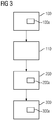
- FIG. 3 shows a flowchart of the inventive method for checking a plurality of mutually insulated individual conductors of the stator winding rod 1.
- a test signal U1 is coupled into the plurality of individual conductors of the stator winding rod 1.
- the plurality of individual conductors may comprise all of the individual conductors present in the stator winding rod 1, and it is also possible without restriction that coupling in step 100 takes place only in selected ones of the individual conductors of the stator winding rod 1 which are insulated from one another.
- the step 100 may alternatively or additionally include a step of coupling 100a the test signal into at least a second selection of the plurality of individual conductors of the stator winding rod at a second portion or at a second portion second end portion 1b of the stator winding rod 1 include.
- the method can advantageously comprise a step 110 of closing a second end section of the stator winding rod 1.
- the conclusion can be made by short circuit, a resistance Z or the characteristic impedance Z0 of the stator winding rod 1.
- termination 110 occurs at the end portion of the stator winding rod 1 which is not used for coupling 100 the test signal.
- the reflec- ting behavior changes for the correctly insulated individual conductors. It may be advantageous to complete all individual conductors into which the test signal is coupled in step 100 in step 110.
- the method comprises according to FIG. 3 further comprising a step of determining 200 a portion of the test signal U1.
- the determination 200 may be the determination 200 of the first reflection component U2 and / or the transmission component U3 of the test signal U1.
- the second reflection component U2 'of the test signal U1 it is optionally possible for the second reflection component U2 'of the test signal U1 to be determined in a step 200a.
- a step 300 at least the first reflection component U2 and / or the transmission component U3 is compared with a reference signal Uref in order to determine damage to insulation between individual ones of the plurality of individual conductors.
- the step of comparing 300 may also include comparing 300a at least the second reflection component U2 'with the reference signal Uref and / or the first reflection component U2.
- the steps 300, 300a of the method may be related to FIGS. 2a and 2b include described possibilities of comparison.
- the inventive device 10 for checking a plurality of individual conductors in a stator winding rod 1 of an electric machine is in FIGS. 1a and 1b shown.
- the device 10 comprises a voltage source 12 for providing and coupling a test signal U1 into the plurality of individual conductors of a stator winding rod 1.
- the device 10 further comprises a measuring device 14.
- the measuring device 14 may be, for example, an oscilloscope.
- the measuring device 14 is used to determine a reflection component U2, a second reflection component U2 'and / or a transmission component U3 of the test signal U1.
- the measuring device 14 can enable an analysis of the reflection components U2 and / or U2 'with respect to a reference signal Uref.
- the reference signal Uref typically characterizes a corresponding signal for a stator winding rod 1, the insulation of which is undamaged between the individual individual conductors.
- the device 10 may further comprise means for coupling the test signal U1 into the plurality of individual conductors.
- the corresponding agents are known in the art and in FIGS. 1a and 1b Not shown.
- the voltage source 12 and the measuring device 14 may also be designed as a device 10.
- the device 10 may further include a resistor Z, Z0 for terminating the stator winding rod.
- the reference signal Uref may be without limitation the one associated with above FIGS. 2a and 2b act described forms of the reference signal.
Landscapes
- Physics & Mathematics (AREA)
- General Physics & Mathematics (AREA)
- Testing Of Short-Circuits, Discontinuities, Leakage, Or Incorrect Line Connections (AREA)
- Tests Of Circuit Breakers, Generators, And Electric Motors (AREA)
- Windings For Motors And Generators (AREA)
Description
Die Erfindung betrifft ein Verfahren zur Überprüfung einer Vielzahl von gegeneinander isolierten Einzelleitern in einem Ständerwicklungsstab einer elektrischen Maschine und eine entsprechende Vorrichtung. In elektrischen Maschinen, insbesondere in rotierenden elektrischen Maschinen, wie zum Beispiel Motoren oder Generatoren, werden sogenannte Ständerwicklungsstäbe verwendet, um die Stromdichte innerhalb der elektrischen Maschine zu verstetigen und induzierte Wirbelströme soweit als möglich zu reduzieren. Dazu sind die rotierenden Maschinen aus einer Vielzahl von Teilleitern bzw. Einzelleitern aufgebaut. Die Einzelleiter sind gegeneinander isoliert mittels einer entsprechenden Teilleiterisolierung, wie sie dem Fachmann bekannt ist. Weiter ist es ein gängiges Vorgehen, die Teilleiter zu verröbeln, um Verluste durch induzierte Wirbelströme zu minimieren. Bei der Herstellung von großen elektrischen Maschinen, die auch als rotierende Maschinen bezeichnet werden können, ist es erforderlich, die Einzelleiter zu verbacken, um die gewünschte Isolation der Einzelleiter, und damit deren galvanische Trennung zu erreichen. Dazu werden die Teilleiter als sogenannte Ständerwicklungsstäbe aufgebaut, die ihrerseits ein gewünschtes Maß an Verröbelung erhalten, und soweit dies erforderlich ist, gebogen werden. Die gewünschte Verröbelung verursacht ebenso wie das Verbiegen eine mechanische Beanspruchung, die dazu führen kann, dass die Einzelleiterisolation beschädigt wird, so dass es zu elektrischen Schlüssen zwischen einzelnen der Einzelleiter eines Ständerwicklungsstabs kommen kann. Diese unerwünschten elektrischen Verbindungen zwischen Einzelleitern, beeinträchtigen die galvanische Isolation der Einzelleiter und führen im Betrieb der Maschine, etwa des Dreh-(strom)motors oder des Generators dazu, dass ein Risiko eines frühzeitigen Ausfalls besteht. Dadurch wird die Lebensdauer und/oder Leistungsfähigkeit der Maschine erheblich beeinträchtigt. Es ist daher von Interesse entsprechende mögliche Verletzungen der Einzelleiterisolation bereits bei der Herstellung zu erkennen. Bisher war es üblich, die Einzelleiter eines Ständerstabs zu überprüfen, bevor der Ständerwicklungs- bzw. der Einzelständerstab, an seinen beiden Enden konsolidiert, d.h. elektrisch mit den weiteren Teilen der Maschine verbunden wurde. Dazu war es üblich, mittels eines geeigneten Messgeräts, etwa eines Multimeters, den Ständerstab bzw. Ständerwicklungsstab auf mögliche Teilleiterschlüsse, das heißt elektrische Verbindung zwischen einzelnen der Einzelleiter zu überprüfen, was auf eine Beschädigung der elektrischen Isolation zwischen einzelnen der Vielzahl von Einzelleitern innerhalb des Ständerwicklungsstabs hinweist. Mittels eines Multimeters war es bisher erforderlich, jeden Einzelleiter gegenüber den übrigen Einzelleitern auf elektrische insbesondere niederohmige Verbindung zu überprüfen.The invention relates to a method for checking a plurality of mutually insulated individual conductors in a stator winding rod of an electrical machine and a corresponding device. In electric machines, particularly in rotating electrical machines, such as motors or generators, so-called stator winding bars are used to stabilize the current density within the electric machine and to reduce induced eddy currents as much as possible. For this purpose, the rotating machines are constructed from a large number of partial conductors or individual conductors. The individual conductors are insulated from each other by means of a corresponding sub-conductor insulation, as is known to the person skilled in the art. Furthermore, it is a common practice to roughen the sub-conductors to minimize losses due to induced eddy currents. In the manufacture of large electrical machines, which can also be referred to as rotating machines, it is necessary to bake the individual conductors in order to achieve the desired isolation of the individual conductors, and thus their galvanic separation. For this purpose, the sub-conductors are constructed as so-called stator winding bars, which in turn receive a desired degree of Verröbelung, and if necessary, be bent. The desired distortion, as well as bending, causes a mechanical stress that can result in damage to the single conductor insulation, which can cause electrical leakage between individual ones of the conductors of a stator winding rod. These unwanted electrical connections between individual conductors impair the galvanic isolation of the individual conductors and, during operation of the machine, such as the rotary current motor or the generator, leads to the risk of premature failure. This will increase the life and / or performance of the machine significantly affected. It is therefore of interest to identify possible possible injuries to the individual conductor insulation already during production. Previously, it was customary to check the individual conductors of a stand rod before the Ständerwicklungs- or the single-stand rod, consolidated at its two ends, ie was electrically connected to the other parts of the machine. For this purpose, it has been customary, by means of a suitable measuring device, such as a multimeter, to check the stator bar or stator winding bar for possible subconductor connections, that is to say electrical connection between individual ones of the individual conductors, resulting in damage to the electrical insulation between individual ones of the plurality of individual conductors within the stator winding bar points. By means of a multimeter, it has hitherto been necessary to check each individual conductor against the other individual conductors for electrical, in particular, low-resistance connection.
Dieses Vorgehen im Stand der Technik war sehr zeit- und kostenintensiv, da es für einen Ständerwicklungsstab, der zum Beispiel aus 50 Einzelleitern aufgebaut ist, die entsprechend gegeneinander verröbelt sind, erforderlich ist, jeden Einzelleiter auf Isolation zu den übrigen Einzelleitern innerhalb des Ständerwicklungsstabs zu überprüfen. Das heißt, es müssen insgesamt 1225 Kombinationen von Einzelleitern überprüft werden. Es sind also zur vollständigen Überprüfung 1225 Messschritte notwendig. Darüber hinaus kann im Stand der Technik die entsprechende Messung mittels des Multimeters, wie oben beschrieben, nur stattfinden, solange die Einzelleiter, die zu dem Ständerwicklungsstab zusammengefügt werden sollen, noch nicht konsolidiert sind. Das heißt, diese Messungen müssen schon vor Aufbringen der entsprechenden Isolation bzw. vor Einbau der Röbelstäbe in das Ständerblechpaket durchgeführt werden, da zu einem späteren Zeitpunkt keine Messung mehr möglich ist. Daraus ergibt sich insbesondere, dass Vorbeschädigungen, zum Beispiel während des Transports, die erst durch zusätzliche mechanische Beanspruchung etwa Pressung nach Einbau der Stäbe bzw. Röbelstäbe in das Blechpaket zu niederohmigen Schlüssen zwischen den Einzelleitern führen, nicht erkannt werden. Das heißt, im Stand der Technik konnte es vorkommen, dass die zeitaufwändige Messung keine Verletzungen der Isolation der Einzelleiter gegeneinander angezeigt hat, obgleich diese nach abgeschlossenem Einbau vorliegt.This prior art approach has been very time consuming and costly because it is necessary for a stator winding bar constructed of, for example, 50 individual conductors that are correspondingly roughened against each other, to check each individual conductor for isolation to the remaining individual conductors within the stator winding rod , This means that a total of 1225 combinations of individual leaders must be checked. So 1225 measuring steps are necessary for a complete check. Moreover, in the prior art, the corresponding measurement by means of the multimeter, as described above, can only take place as long as the individual conductors to be joined to the stator winding rod have not yet been consolidated. That is, these measurements must be carried out before the installation of the corresponding insulation or before installing the Röbelstäbe in the stator core, since at a later date, no measurement is possible. This results in particular that pre-damage, for example, during transport, the only by additional mechanical stress such as pressure after installation of the rods or Röbelstäbe in the laminated core to low-impedance closures between the individual conductors, are not recognized. That is, in the prior art, it could happen that the time-consuming measurement has not indicated any injury to the isolation of the individual conductors against each other, although this is present after completion of installation.
Diese Probleme werden durch das erfindungsgemäße Verfahren zur Überprüfung einer Vielzahl von gegeneinander isolierten Einzelleitern in einem Ständerwicklungsstab einer elektrischen Maschine nach Anspruch 1 behoben, denn durch das erfindungsgemäße Verfahren werden elektrische Verbindungen, insbesondere niederohmige Schlüssel zwischen einzelnen der Einzelleiter auch nach Fertigstellung des Ständerwicklungsstabs detektierbar. Eine entsprechende Vorrichtung zur Überprüfung einer Vielzahl von Einzelleitern in einem Ständerwicklungsstab einer elektrischen Maschine gemäß der vorliegenden Erfindung löst ebenso die Probleme im Stand der Technik.These problems are solved by the inventive method for checking a plurality of mutually insulated individual conductors in a stator winding rod of an electric machine according to
Aufgabe der Erfindung ist es ein Verfahren und eine Vorrichtung zur Überprüfung einer Vielzahl von gegeneinander isolierten Einzelleitern in einem Ständerwicklungsstab einer elektrischen Maschine bereitzustellen, das auch fertig hergestellte Ständerwicklungsstäbe zuverlässig auf eine Verletzung der Isolierung zwischen einzelnen der Vielzahl der Einzelleiter überprüfen kann. Ebenso ist es ein Vorteil des vorliegenden Verfahrens und der Vorrichtung gemäß der Erfindung, dass eine einzelne Messung zum Überprüfen der Einzelleiter innerhalb des Ständerwicklungsstabs ausreichend ist. Dadurch wird die Überprüfung eines fertig hergestellten Ständerwicklungsstabs zeitsparender und kostengünstiger möglich als im Stand der Technik.The object of the invention is to provide a method and a device for checking a plurality of mutually insulated individual conductors in a stator winding rod of an electric machine that can reliably check also manufactured stator winding bars to a violation of the insulation between each of the plurality of individual conductors. Likewise, it is an advantage of the present method and apparatus according to the invention that a single measurement is sufficient to check the individual conductors within the stator winding rod. As a result, the review of a finished manufactured stator winding rod is time-saving and cheaper possible than in the prior art.
Das erfindungsgemäße Verfahren zur Überprüfung einer Vielzahl von gegeneinander isolierten Einzelleitern in einem Ständerwicklungsstab einer elektrischen Maschine gemäß Anspruch 1 umfasst einen Schritt des Einkoppelns eines Prüfsignals, einen Schritt des Ermittelns eines ersten Anteils des Prüfsignals und einen Schritt des Vergleichens. Der Schritt des Einkoppelns eines Prüfsignals umfasst ein Einkoppeln des Prüfsignals in eine Vielzahl von Einzelleitern des Ständerwicklungsstabs. Der Schritt des Vergleichens umfasst erfindungsgemäß ein Vergleichen zumindest des ersten Anteils des Prüfsignals mit einem Referenzsignal, um so eine Beschädigung einer Isolierung, das heißt einer galvanischen Trennung zwischen einzelnen der Vielzahl der Einzelleiter zu ermitteln.The inventive method for testing a plurality of mutually insulated individual conductors in a stator winding rod of an electric machine according to
Dieses Verfahren ist vorteilhaft, um eine Vielzahl von Einzelleitern innerhalb des Ständerwicklungsstabs mit nur einer Messung zu überprüfen. Dadurch wird die Qualitätssicherung des Ständerwicklungsstabs kosten- und zeitgünstiger. Unter Einkoppeln ist zu verstehen, dass ein Prüfsignal in die Vielzahl von Einzelleitern des Ständerwicklungsstabs eingebracht wird. Dem Fachmann sind entsprechende Verfahren bekannt. So kann das Einkoppeln über eine elektrische Verbindung, eine induktive Kopplung und/oder eine kapazitive Kopplung zwischen einer Signalquelle und dem Ständerwicklungsstab erfolgen, so dass der Ständerwicklungsstab und damit Einzelleiter des Ständerwicklungsstabs mit dem Prüfsignal beaufschlagt sind. Unter dem ersten Reflexionsanteil des Prüfsignals ist jener Anteil des Prüfsignals zu verstehen, der von der Vielzahl der Einzelleiter reflektiert wird, und daher am Einkoppelpunkt bzw. am Ort des Einkoppelns detektierbar ist.This method is advantageous for checking a plurality of individual conductors within the stator winding rod with only one measurement. As a result, the quality assurance of the stator winding rod is cost and time-saving. Under coupling is to be understood that a test signal is introduced into the plurality of individual conductors of the stator winding rod. The person skilled in the corresponding methods are known. Thus, the coupling can take place via an electrical connection, an inductive coupling and / or a capacitive coupling between a signal source and the stator winding rod, so that the stator winding rod and thus individual conductors of the stator winding rod are subjected to the test signal. The first reflection component of the test signal is that component of the test signal which is reflected by the multiplicity of individual conductors and is therefore detectable at the coupling-in point or at the point of coupling.
Vorzugsweise umfasst der Schritt des Ermittelns ein Ermitteln eines ersten Reflektionsanteils des Prüfsignals und/oder eines ersten Transmissionsanteils. Daraus ergibt sich der Vorteil, dass für die Prüfung der Ständerwicklungsstäbe wahlweise nur eine oder zwei Verbindungen mit dem Ständerwicklungsstab erforderlich sind. Der Fachmann hat also eine Freiheit, wie die Prüfung der Ständerwicklungsstäbe zu erfolgen hat. Darüber hinaus ergeben sich aus dem Ermitteln von Reflektionsanteil und Transmissionsanteil zwei Größen, die in eine Fehlerprüfung eingehen können.Preferably, the step of determining comprises determining a first reflection component of the test signal and / or of a first transmission component. This results in the advantage that only one or two connections to the stator winding rod are required for testing the stator winding bars. The skilled person thus has a freedom as to how to test the stator winding bars. In addition, the determination of the reflection component and the transmission component result in two variables that can be included in an error check.
Vorzugsweise umfasst der Schritt des Einkoppelns ein Einkoppeln an einem ersten Abschnitt des Ständerwicklungsstabs oder an einem ersten Endabschnitt des Ständerwicklungsstabs. Es kann vorteilhaft sein, den Schritt des Einkoppelns an einem ersten Abschnitt des Ständerwicklungsstabs vorzunehmen, der nicht ein Endabschnitt des Ständerwicklungsstabs ist. Dies kann sich zum Beispiel aus Fertigungsgegebenheiten ergeben. Wird das Prüfsignal an einem ersten Abschnitt eingekoppelt, der nicht Endabschnitt des Ständerwicklungsstabs ist, so kann dies bedeuten, dass nicht die gesamte Länge der Einzelleiter innerhalb des Ständerwicklungsstabs überprüft werden.Preferably, the step of coupling comprises coupling to a first portion of the stator winding rod or to a first end portion of the stator winding rod. It may be advantageous to perform the step of coupling to a first portion of the stator winding rod that is not an end portion of the stator winding rod. This can result, for example, from production conditions. If the test signal is coupled in at a first section which is not the end section of the stator winding rod, this may mean that not the entire length of the individual conductors within the stator winding rod is checked.
Ebenso ist es denkbar, das Prüfsignal an einem ersten Endabschnitt des Ständerwicklungsstabs einzukoppeln, da dieser Endabschnitt mit weiteren Abschnitten der elektrischen Maschine im weiteren Fertigungsprozess verbunden wird, wodurch sich sicherstellen lässt, dass im Wesentlichen die gesamte Länge des im Folgenden zu konsolidierenden Ständerwicklungsstabs frei von Beschädigungen der Isolierung zwischen einzelnen der Vielzahl der Einzelleiter ist. Durch die Wahlfreiheit des Einkoppelpunkts als ersten Abschnitt und/oder ersten Endabschnitt des Ständerwicklungsstabs lässt sich das erfindungsgemäße Verfahren an jeweils vorliegende Gegebenheiten während des Fertigungsprozesses flexibel anpassen. Es ist weiter bevorzugt den Schritt des Ermittelns als ein Ermitteln des ersten Reflexionsanteils an den ersten Abschnitt oder an dem ersten Endabschnitt des Ständerwicklungsstabs auszuführen. Wenn der Ort des Einkoppelns bzw. der Abschnitt zum Einkoppeln und zum Ermitteln gleich sind, vereinfacht sich das erfindungsgemäße Verfahren weiter. Dadurch lässt sich das erfindungsgemäße Verfahren zeit- und kostengünstiger durchführen.It is also conceivable to couple the test signal to a first end section of the stator winding rod, since this end section is connected to further sections of the electric machine in the further manufacturing process, thereby ensuring that substantially the entire length of the stator winding rod to be subsequently consolidated is free of damage the isolation between each of the plurality of individual conductors is. Due to the freedom of choice of the coupling-in point as the first section and / or the first end section of the stator winding rod, the method according to the invention can be flexibly adapted to prevailing conditions during the production process. It is further preferable to have the step of determining as determining of the first reflection portion to the first portion or at the first end portion of the stator winding rod. If the location of the coupling or the section for coupling and for determining are identical, the method according to the invention simplifies further. As a result, the method according to the invention can be carried out in a time and cost-effective manner.
Bevorzugt kann das erfindungsgemäße Verfahren ein Abschließen eines zweiten Endabschnitts des Ständerwicklungsstabs umfassen. Ein Abschließen des Ständerwicklungsstabs an dessen zweitem Ende hat den Vorteil, dass sich für die elektrisch nicht verbundenen Einzelleiter innerhalb des Ständerwicklungsstabs definierte Reflexionseigenschaften erreichen lassen. So kann das Abschließen einen Kurzschluss, einen gewünschten Widerstand oder den Wellenwiderstand des Ständerwicklungsstabs umfassen.The method according to the invention may preferably include a termination of a second end section of the stator winding rod. Completing the stator winding rod at its second end has the advantage that it is possible to achieve defined reflection properties for the electrically unconnected individual conductors within the stator winding rod. Thus, the termination may include a short circuit, a desired resistance or the characteristic impedance of the stator winding rod.
Es ist weiter bevorzugt, dass der Schritt des Abschließens ein Abschließen zumindest einer ersten Auswahl der Einzelleiter innerhalb des Ständerwicklungsstabs umfasst. Dadurch ergibt sich für die erste Auswahl der Einzelleiter ein definiertes Reflexionsverhalten, sofern die Isolierung zwischen den Einzelleitern der ersten Auswahl nicht beschädigt ist. Es ist weiter bevorzugt, dass der Schritt des Abschließens ein Abschließen der Vielzahl der Einzelleiter an dem zweiten Ende des Ständerwicklungsstabs umfasst, die durch das erfindungsgemäße Verfahren überprüft werden. Dies hat den Vorteil, dass die durch das Verfahren überprüfte Vielzahl von gegeneinander isolierten Einzelleitern in dem Ständerwicklungsstab ein definiertes Reflexionsverhalten zeigen, sofern die Isolierung zwischen diesen nicht beschädigt ist. Da die Anzahl der Einzelleiter innerhalb des Ständerwicklungsstabs bekannt ist, kann es weiter von Vorteil sein, sämtliche der Einzelleiter innerhalb des Ständerwicklungsstabs durch den gewünschten Widerstand, Kurzschluss oder Wellenwiderstand abzuschließen, um für sämtliche Einzelleiter innerhalb des Ständerwicklungsstabs definierte Reflexionseigenschaften zu erreichen, sofern die Einzelleiter galvanisch getrennt sind, das heißt sofern die Isolierung zwischen allen Einzelleitern des Ständerwicklungsstabs nicht beschädigt ist.It is further preferred that the closing step comprises completing at least a first selection of the single conductors within the stator winding rod. This results in a defined reflection behavior for the first selection of the individual conductors, provided that the insulation between the individual conductors of the first selection is not damaged. It is further preferred that the step of closing comprises closing off the plurality of individual conductors at the second end of the stator winding rod, which are checked by the method according to the invention. This has the advantage that the plurality of mutually insulated individual conductors checked by the method exhibit a defined reflection behavior in the stator winding rod, as long as the insulation between them is not damaged. Since the number of individual conductors within the stator winding rod is known, it may further be advantageous to terminate all of the individual conductors within the stator winding rod by the desired resistance, short circuit or characteristic impedance in order to achieve defined reflection properties for all individual conductors within the stator winding rod, if the individual conductors are galvanically isolated, that is, unless the insulation between all the individual conductors of the stator winding rod is damaged.
Bevorzugt umfasst der Schritt des Vergleichens ein Referenzsignal, das ein Überlagerungsreferenzsignal ist. Das Überlagerungsreferenzsignal wird mit einem Überlagerungssignal aus dem ersten Reflexionsanteil und dem Prüfsignal verglichen. Dieses Vorgehen hat den Vorteil, dass die Prüfung der Einzelleiter an einem Ende des Ständerwicklungsstabs möglich ist. Dadurch wird der für das Verfahren erforderliche Messaufbau vereinfacht.Preferably, the step of comparing comprises a reference signal that is a beat reference signal. The beat reference signal is compared with a beat signal from the first reflectance component and the test signal. This procedure has the advantage that it is possible to test the individual conductors at one end of the stator winding rod. This simplifies the measurement setup required for the procedure.
Weiter bevorzugt kann das Verfahren ein Einkoppeln des Prüfsignals in eine zweite Auswahl der Einzelleiter des Ständerwicklungsstabs umfassen. Das Einkoppeln in die zweite Auswahl der Vielzahl der Einzelleiter kann an einem zweiten Abschnitt, insbesondere an einem zweiten Endabschnitt des Ständerwicklungsstabs erfolgen. Weiter kann das Verfahren ein Ermitteln eines zweiten Reflexionsanteils an dem zweiten Abschnitt oder dem zweiten Endabschnitt des Ständerwicklungsstabs umfassen. Das Vergleichen kann ein Vergleichen zumindest des zweiten Reflexionsanteils mit dem Referenzsignal und/oder dem ersten Reflexionsanteil umfassen. Durch dieses Vorgehen kann die Prüfung der Einzelleiter des Ständerwicklungsstabs sowohl an dessen erstem Ende als auch an dessen zweitem Ende erfolgen. Sofern die Reflexionsanteile an den beiden Abschnitten bzw. Endabschnitten voneinander abweichen, ist dies ein Hinweis auf eine Beschädigung der Isolierung zwischen den Einzelleitern innerhalb des Ständerwicklungsstabs und damit einer beeinträchtigten galvanischen Trennung dieser Einzelleiter.More preferably, the method may include coupling the test signal into a second selection of the individual conductors of the stator winding rod. The coupling into the second selection of the plurality of individual conductors can take place on a second section, in particular on a second end section of the stator winding rod. Furthermore, the method may comprise determining a second reflection component at the second section or the second end section of the stator winding rod. The comparing may comprise comparing at least the second reflection component with the reference signal and / or the first reflection component. By this procedure, the examination of the individual conductors of the stator winding rod can take place both at its first end and at its second end. If the reflection components at the two sections or end sections deviate from each other, this is an indication of damage to the insulation between the individual conductors within the stator winding rod and thus an impaired galvanic separation of these individual conductors.
Weiter bevorzugt umfasst das Prüfsignal einen zeitlichen Spannungsverlauf mit mindestens einer Flanke definierter Steilheit. Dabei ist definierte Steilheit dahingehend zu verstehen, dass in der Steilheit der Flanke ausreichend hohe Frequenzanteile enthalten sind, um eine mögliche Veränderung des Reflexionsanteils zuverlässig detektieren zu können, wie sie durch Beschädigung der Isolierung auftreten kann.More preferably, the test signal comprises a temporal voltage curve with at least one edge defined slope. In this case, defined steepness is to be understood as meaning that sufficiently high frequency components are contained in the slope of the edge in order to detect a possible change the reflection component can reliably detect how it can occur due to damage to the insulation.
Weiter kann das Prüfsignal einen zeitlichen Spannungsverlauf mit mindestens einem Spannungsimpuls mit mindestens einer Flanke definierter Steilheit umfassen. Ebenso ist es möglich, dass der Spannungsimpuls zwei Flanken der definierten Steilheit umfasst. Weiter bevorzugt kann die definierte Steilheit einige Volt innerhalb weniger Nanosekunden oder Mikrosekunden betragen, vorzugsweise 0,1 bis 10 Volt pro Mikrosekunde oder höher betragen. Wobei die angegebenen Werte nur beispielhaft zu verstehen sind und keine Beschränkung der Erfindung darstellen.Furthermore, the test signal may include a temporal voltage curve with at least one voltage pulse with at least one edge of defined slope. It is also possible that the voltage pulse comprises two edges of the defined slope. More preferably, the defined slope may be a few volts within a few nanoseconds or microseconds, preferably 0.1 to 10 volts per microsecond or higher. The stated values are only to be understood as examples and do not represent a limitation of the invention.
Weiter bevorzugt kann das Prüfsignal einen zeitlichen Spannungsverlauf mit mindestens einem Maximum von einigen Volt, vorzugsweise 0,1 bis 80 Volt umfassen, diese Merkmale des zeitlichen Spannungsverlaufs haben den Vorteil, dass keine besonderen Sicherheitsvorkehrungen notwendig sind, wenn der Ständerwicklungsstab gemäß des erfindungsgemäßen Verfahrens überprüft wird. Wobei die angegebenen Werte nur beispielhaft zu verstehen sind und keine Beschränkung der Erfindung darstellen.Further preferably, the test signal may comprise a temporal voltage curve with at least a maximum of a few volts, preferably 0.1 to 80 volts, these characteristics of the temporal voltage curve have the advantage that no special safety precautions are necessary when the stator winding rod is checked according to the inventive method , The stated values are only to be understood as examples and do not represent a limitation of the invention.
Die Erfindung schlägt weiter eine Vorrichtung zur Überprüfung einer Vielzahl von Einzelleitern in einem Ständerwicklungsstab einer elektrischen Maschine gemäß Anspruch 8 vor. Die Maschine umfasst eine Signalquelle und eine Messvorrichtung. Die Signalquelle ist eingerichtet zum Bereitstellen und Einkoppeln eines Prüfsignals in eine Vielzahl von Einzelleitern des Ständerwicklungsstabs. Die Messvorrichtung ist eingerichtet zum Ermitteln eines Reflexionsanteils und/oder eines Transmissionsanteils des Prüfsignals und zum Analysieren des Reflexionsanteils und/oder des Transmissionsanteils in Bezug auf ein Referenzsignal.The invention further proposes a device for checking a plurality of individual conductors in a stator winding rod of an electric machine according to claim 8. The machine includes a signal source and a measuring device. The signal source is arranged to provide and couple a test signal into a plurality of individual conductors of the stator winding rod. The measuring device is set up to determine a reflection component and / or a transmission component of the test signal and to analyze the reflection component and / or the transmission component in relation to a reference signal.
Weiter bevorzugt kann das Referenzsignal ein Überlagerungsreferenzsignal sein, und mit einen Überlagerungssignal aus dem ersten Reflexionsanteil und dem Prüfsignal ist. Dem Fachmann sind verschiedene Möglichkeiten, ein Überlagerungssignal zu erzeugen, bekannt, so kann das Überlagerungssignal zum Beispiel eine Addition aus dem Prüfsignal und des Reflexionssignals umfassen. Dadurch wird das resultierende Überlagerungssignal um den Reflexionsanteil reduziert. Ebenso ist es möglich, das Prüfsignal und den Reflexionsanteil gegeneinander aufzutragen, um sogenannte Lissajous-Figuren zu erzeugen. Dazu ist es bekanntermaßen vorteilhaft, dass das Prüfsignal entsprechende Wechselspannungsanteile enthält. Ebenso sind weitere Formen von Überlagerungssignalen und/oder Überlagerungsreferenzsignalen bekannt. Es ist vorteilhaft, das Überlagerungssignal aus Prüfsignal und Reflexionsanteil so zu wählen, dass sich im Falle einer Beschädigung der Isolation ein deutlicher Unterschied zu dem Überlagerungsreferenzsignal eines unbeschädigten Ständerwicklungsstabs, das heißt eines Ständerwicklungsstabs mit unbeschädigter Isolierung im Fehlerfall ergibt. Dabei ist der Fehlerfall zu verstehen als ein Ständerwicklungsstab, in dem zumindest eine Beschädigung der Isolierung zwischen den gegeneinander isolierten Einzelleitern besteht, so dass sich ein niederohmiger Schluss zwischen einzelnen der Einzelleiter ergibt.More preferably, the reference signal may be a beat reference signal, and with a beat signal from the first reflection component and the test signal. The person skilled in various ways to generate a beat signal, known, the overlay signal may include, for example, an addition of the test signal and the reflection signal. As a result, the resulting beat signal is reduced by the reflection component. It is also possible to apply the test signal and the reflection component against each other to produce so-called Lissajous figures. For this purpose, it is known that it is advantageous that the test signal contains corresponding alternating voltage components. Likewise, other forms of beat signals and / or beat reference signals are known. It is advantageous to select the beat signal from the test signal and the reflection component so that, in the event of damage to the insulation, there is a significant difference to the overlay reference signal of an undamaged stator winding rod, ie a stator winding rod with undamaged insulation in the event of a fault. In this case, the fault is to be understood as a stator winding rod in which there is at least a damage of the insulation between the mutually insulated individual conductors, so that there is a low-impedance conclusion between each of the individual conductors.
Weiter bevorzugt handelt es sich bei der elektrischen Maschine um einen Generator. Dies ist vorteilhaft, da damit durch die erfindungsgemäße Vorrichtung Ständerwicklungsstäbe, wie sie in einem Generator zum Einsatz kommen, überprüft werden können. Ohne Einschränkung kann es sich bei der elektrischen Maschine auch um jede rotierende elektrische Maschine handeln, etwas einen Elektromotor oder den bereits erwähnten Generator. Daraus ergibt sich der Vorteil insbesondere große rotierende elektrische Maschinen schon bei deren Zusammenbau auf Korrektheit, das heißt die gewünschte elektrische Isolierung zwischen einzelnen der Einzelleiter hin zu überprüfen. Dadurch wird ein möglicher Leistungsverlust der elektrischen Maschine verhindert.More preferably, the electrical machine is a generator. This is advantageous because it can be checked by the inventive device stator winding rods, such as those used in a generator. Without limitation, the electric machine can also be any rotating electrical machine, something an electric motor or the already mentioned generator. This results in the advantage, in particular large rotary electric machines already during their assembly on correctness, that is to check the desired electrical insulation between each of the individual conductors out. This prevents a possible loss of power of the electrical machine.
Im Folgenden werden bevorzugte Ausführungsformen des erfindungsgemäßen Verfahrens und der erfindungsgemäßen Vorrichtung anhand der beigefügten schematischen Zeichnung erläutert. Es zeigen:
Figur 1a- eine erste Anordnung zur Durchführung des erfindungsgemäßen Verfahrens,
Figur 1b- eine zweite Anordnung zur Durchführung des erfindungsgemäßen Verfahrens,
- Figur 2a
- einen beispielhaften Verlauf von Referenzsignalen Uref und Reflexionsanteilen im Falle eines Überlagerungssignals U1+U2,
- Figur 2b
- einen schematischen Signalverlauf des Referenzsignals Uref für den Reflexionsanteil im Falle einer unbeschädigten Isolierung und einer fehlerhaften Isolierung, und
- Figur 3
- einen Ablaufplan des erfindungsgemäßen Verfahrens.
- FIG. 1a
- a first arrangement for carrying out the method according to the invention,
- FIG. 1b
- a second arrangement for carrying out the method according to the invention,
- FIG. 2a
- an exemplary course of reference signals Uref and reflection components in the case of a beat signal U1 + U2,
- FIG. 2b
- a schematic waveform of the reference signal Uref for the reflection component in the case of undamaged insulation and faulty insulation, and
- FIG. 3
- a flow chart of the method according to the invention.
Dem Fachmann sind geeignete Mittel zum Einkoppeln 100 des Prüfsignals als erstem Verfahrensschritt bekannt. So kann das Einkoppeln 100 zum Beispiel eine elektrische Verbindung, ein kapazitives Einkoppeln und/oder ein induktives Einkoppeln des Prüfsignals U1 bedeuten. In
Sind nun aufgrund von Beschädigungen einer Isolation der Einzelleiter des Ständerwicklungsstabs 1 gegeneinander niederohmige Verbindungen oder Schlüsse zwischen einzelnen der Einzelleiter des Ständerwicklungsstabs 1 vorhanden, so ändert sich an diesen Fehlstellen der Wellenwiderstand des Ständerwicklungsstabs 1. Mit der Änderung des Wellenwiderstands des Ständerwicklungsstabs 1 geht auch eine Änderung des Reflexionsanteils U2 und des Transmissionsanteils U3 einher. Bei dem Einkoppeln 100 des Referenzsignals U1 in den ersten Endabschnitt 1a bzw. den ersten Abschnitt des Ständerwicklungsstabs 1 kann der dort gemessene Reflexionsanteil U2 auch als ein erster Reflexionsanteil bezeichnet werden. Der erste Reflexionsanteil U2 wird in einem Schritt des Ermittelns 200 bestimmt bzw. gemessen. Die deutliche Änderung dieses ersten Reflexionsanteils U2 im Fall einer niederohmigen Verbindung zwischen einzelnen der Einzelleiter lässt sich in einem Vergleichsschritt 300 des Verfahrens bestimmen. Dazu wird der erste Reflexionsanteil U2 mit einem Referenzsignal Uref für den fehlerfreien Fall verglichen, um eine Beschädigung der Isolierung zwischen einzelnen der Einzelleiter zu ermitteln. Dazu kann zum Beispiel eine Messvorrichtung 14 verwendet werden, etwa in Form eines Oszilloskops.Are now due to damage to insulation of the individual conductors of the
Der Fachmann wird verstehen, dass aufgrund der deutlichen Änderung des Wellenwiderstands im Fehlerfall auch eine deutliche Änderung eines Transmissionsanteils U3 des Prüfsignals U1 zur Detektion von Beschädigungen der Isolierung, das heißt niederohmigen Verbindungen zwischen einzelnen der Einzelleiter verwendet werden kann. Zur Messung des Transmissionsanteils U3 könnte die Messvorrichtung 14 auch an dem zweiten Endabschnitt 1b des Ständerwicklungsstabs 1 angebracht sein (nicht gezeigt).The skilled person will understand that due to the significant change in the characteristic impedance in case of failure and a significant change in a transmission component U3 of the test signal U1 for detecting damage to the insulation, that is, low-resistance connections between each of the individual conductors can be used. For measuring the transmission component U3, the measuring
Für den in
Es ist von Vorteil, dass das Einkoppeln 100a des Prüfsignals U1 in dieselben Einzelleiter erfolgt, die schon für das Einkoppeln 100 an dem ersten Abschnitt bzw. Endabschnitt 1a verwendet wurden. Weichen für diese beiden Messungen die jeweiligen Reflexionsanteile U2, U2' ab, so dass der erste Reflexionsanteil U2 an dem ersten Abschnitt bzw. Endabschnitt 1a verschieden ist von einem zweiten Reflexionsanteil U2 an dem zweiten Abschnitt bzw. Endabschnitt 1b des Ständerwicklungsstabs 1, so ist dies ein Hinweis auf Beschädigung der Einzelleiter. Das heißt, in einem Schritt des Vergleichens 300a des zweiten Reflexionsanteils U2' mit einem Referenzsignal Uref und/oder dem ersten Reflexionsanteil U2 ergibt sich ein deutlicher Unterschied, der auf die Beschädigung der Isolation der Einzelleiter gegeneinander hinweist.It is advantageous that the
Für den in
Der Fachmann wird verstehen, dass im Falle einer Ermittlung des ersten Reflexionsanteils U2 an dem ersten Endabschnitt 1a und des zweiten Reflexionsanteils U2' (nicht gezeigt) an dem zweiten Endabschnitt 1b des Ständerwicklungsstabs 1 möglicherweise ein zur Länge des Ständerwicklungsstabs 1 symmetrisches Auftreten von Beschädigungen der Isolation bei dem Schritt des Vergleichens 300a übersehen werden kann.It will be understood by those skilled in the art that if the first reflectance portion U2 at the
Es ist vorteilhaft, ein Überlagerungssignal U1+U2 über der Zeit aufzutragen, da im Fehlerfall das Überlagerungssignal U1+U2 abnimmt, so dass sich eine deutliche Abweichung zwischen dem Referenzsignal Uref und dem Überlagerungssignal U1+U2 ergibt. Dem Fachmann sind weitere Möglichkeiten von Überlagerungssignalen bekannt. Ohne Einschränkung könnte zum Beispiel der in Schritt 200 ermittelte Reflexionsanteil U2, U2' vergrößert oder verstärkt werden, um die Abweichung noch deutlicher zu machen. Es ist daher möglich, geeignete Darstellungen zu wählen, so dass sich in dem Schritt des Vergleichens 300a ein deutlicher Unterschied zwischen dem fehlerfreien Ständerwicklungsstab und einem fehlerhaften Ständerwicklungsstab ergibt.It is advantageous to apply a beat signal U1 + U2 over time, since in the event of an error the beat signal U1 + U2 decreases, resulting in a significant deviation between the reference signal Uref and the beat signal U1 + U2. The person skilled in the art knows further possibilities of heterodyne signals. Without limitation, for example, the reflection component U2, U2 'determined in
Ohne Einschränkung könnte in dem Schritt des Ermittelns 200 anstelle des ersten Reflexionsanteils U2 bzw. des zweiten Reflexionsanteils U2' auch der am jeweils gegenüberliegenden Abschnitt bzw. Endabschnitt des Ständerwicklungsstabs 1 der nicht zum Einkoppeln verwendet wird, gemessene Transmissionsanteil U3, zur Ermittlung einer Beschädigung der Isolierung der Einzelleiter des Ständerwicklungsstabs gegeneinander verwendet werden. Die deutliche Änderung des Wellenwiderstands im Falle einer niederohmigen Verbindung einzelner der Einzelleiter wird sich auch auf den Transmissionsanteil U3 auswirken.Without restriction, in the step of determining 200, instead of the first reflection component U2 or the second reflection component U2 ', the transmission component U3, measured at the respectively opposite section or end section of the
Dem Fachmann sind weitere Möglichkeiten bekannt, um ein Überlagerungssignal aus Prüfsignal U1, dessen Reflexionsanteil U2, U2', und/oder dem Transmissionsanteil U3 zu erzeugen, um einen deutlichen Unterschied bei dem Schritt des Ermittelns 300, 300a zwischen einer unbeschädigten Isolierung und einer beschädigten Isolierung zu erreichen. Denkbar sind zum Beispiel Darstellungen ausgewählter Signale aus dem Prüfsigna U1, dem Reflexionsanteil U2, U2' und/oder dem Transmissionsanteil U3 gegeneinander in Form von Lissajous-Figuren. Die in
Dem Fachmann sind darüber hinaus Verfahren bekannt, um aus zu erwartenden Signalverläufen für den Fehlerfall und den fehlerfreien Fall Masken zu erstellen, so dass gegebenenfalls automatisch zwischen beiden Fällen unterschieden werden kann.Other ways are known to those skilled in the art to generate a beat signal from the test signal U1, its reflection component U2, U2 ', and / or the transmission component U3, by a significant difference in the step of determining 300, 300a between undamaged insulation and damaged insulation to reach. Conceivable, for example, representations of selected signals from the Prüfsigna U1, the reflection component U2, U2 'and / or the transmission component U3 against each other in the form of Lissajous figures. In the
In addition, methods are known to the person skilled in the art in order to create masks from expected signal progressions for the error case and the error-free case, so that, if necessary, a distinction can be automatically made between the two cases.
Weiter kann das Verfahren vorteilhaft einen Schritt 110 des Abschließens eines zweiten Endabschnitts des Ständerwicklungsstabs 1 umfassen. Das Abschließen kann durch Kurzschluss, einen Widerstand Z oder den Wellenwiderstand Z0 des Ständerwicklungsstabs 1 erfolgen. Typischerweise erfolgt das Abschließen 110 an dem Endabschnitt des Ständerwicklungsstabs 1, der nicht zum Einkoppeln 100 des Prüfsignals verwendet wird. Wie beschrieben ändert sich durch den Schritt des Abschließens das Reflexionsverhalten für die korrekt gegeneinander isolierten Einzelleiter. Es kann von Vorteil sein alle Einzelleiter, in welche das Prüfsignal in dem Schritt 100 eingekoppelt wird, in Schritt 110 auch abzuschließen.Furthermore, the method can advantageously comprise a
Das Verfahren umfasst gemäß
In einem Schritt 300 wird zumindest der erste Reflexionsanteil U2 und/oder der Transmissionsanteil U3 mit einem Referenzsignal Uref verglichen, um eine Beschädigung einer Isolierung zwischen einzelnen der Vielzahl der Einzelleiter zu ermitteln. Optional kann der Schritt des Vergleichens 300 auch ein Vergleichen 300a zumindest des zweiten Reflexionsanteils U2' mit dem Referenzsignal Uref und/oder dem ersten Reflexionsanteil U2 umfassen. Die Schritte 300, 300a des Verfahrens können den im Zusammenhang mit
Die erfindungsgemäße Vorrichtung 10 zur Überprüfung einer Vielzahl von Einzelleitern in einem Ständerwicklungsstab 1 einer elektrischen Maschine ist in
Claims (9)
- Method for checking a multiplicity of mutually insulated strands in a stator winding bar (1) of an electrical machine, the method comprising:- injecting (100) a test signal (U1) into the multiplicity of strands of the stator winding bar (1), wherein the step of injection (100) comprises an injection at a first segment of the stator winding bar (1) or at a first end segment (1a) of the stator winding bar (1),- detecting (200) a first component (U2) of the test signal (U1), wherein the step of detection (200) comprises a detection of a first reflection component (U2) at the first segment or at the first end segment (1a),- injecting (100a) the test signal (U1) into at least a second selection of the multiplicity of strands of the stator winding bar (1) at a second segment of the stator winding bar (1) or at a second end segment (1a) of the stator winding bar (1),- detecting (200a) a second reflection component (U2') at the second segment or the second end segment (1b),- comparing (300) at least the first component of the test signal (U1) with a reference signal (Uref) in order to detect damage to an insulation between individual strands of the multiplicity of strands, wherein the reference signal (Uref) is a superposition reference signal that is compared with a superposition signal (U1+U2) of the first reflection component (U2) and the test signal (U1) and- comparing (300a) at least the second reflection component (U2') with the reference signal, wherein the reference signal (Uref) is a superposition reference signal that is compared with a superposition signal (U1+U2') of the second reflection component (U2') and the test signal (U1).
- Method according to one of the previous claims, further comprising:- terminating (110) a second end segment (1b) of the stator winding bar (1) by a short circuit, a resistor (Z) or the characteristic impedance (Z0) of the stator winding bar (1).
- Method according to Claim 2,
wherein the step of termination (110) comprises a termination of at least a first selection of the multiplicity of strands, preferably the multiplicity of strands at the second end (1b) of the stator winding bar. - Method according to one of the previous claims,
wherein the test signal (U1) comprises a temporal voltage curve with at least one edge of a defined gradient. - Method according to one of the previous claims,
wherein the test signal (U1) comprises a temporal voltage curve with at least one voltage pulse with at least one edge of defined gradient. - Method according to one of Claims 1 or 5,
wherein the defined gradient amounts to a few volts within a few nanoseconds, preferably 0.1 to 10 volts per nanosecond or higher. - Method according to one of the previous claims,
wherein the test signal (U1) is at least one temporal voltage curve with at least one maximum of a few volts, preferably in the range from 0.1 to 80 volts. - Apparatus (10) for checking a multiplicity of strands in a stator winding bar (1) of an electrical machine, the apparatus (10) comprising:- a signal source (12) configured to provide and inject a test signal (U1) into the multiplicity of strands,- a measuring apparatus (14) configured to detect a reflection component (U2, U2') and/or a transmission component (U3) of the test signal (U1) at a first segment or at a first end segment (1a) of the stator winding bar (1), and a second reflection component (U2') at a second segment or at a second end segment (1b) of the stator winding bar, and to analyze the reflection component (U2, U2') and/or the transmission component (U3) in relation to a reference signal (Uref), wherein the reference signal (Uref) is a superposition signal that is compared both with a superposition signal (U1+U2) of the first reflection component (U2) and the test signal (U1) and with a superposition signal (U1+U2') of the second reflection component (U2') and the test signal (U1).
- Apparatus (10) according to Claim 8, wherein the electrical machine is a generator.
Priority Applications (1)
| Application Number | Priority Date | Filing Date | Title |
|---|---|---|---|
| EP14772081.7A EP3014291B1 (en) | 2013-09-24 | 2014-09-09 | Partial conductor termination test for stator bars of electrical machines |
Applications Claiming Priority (3)
| Application Number | Priority Date | Filing Date | Title |
|---|---|---|---|
| EP13185685.8A EP2851695A1 (en) | 2013-09-24 | 2013-09-24 | Partial continuity test for stator bars of electrical machines |
| PCT/EP2014/069143 WO2015043942A1 (en) | 2013-09-24 | 2014-09-09 | Interstrand short circuit testing of stator winding bars of electric machines |
| EP14772081.7A EP3014291B1 (en) | 2013-09-24 | 2014-09-09 | Partial conductor termination test for stator bars of electrical machines |
Publications (2)
| Publication Number | Publication Date |
|---|---|
| EP3014291A1 EP3014291A1 (en) | 2016-05-04 |
| EP3014291B1 true EP3014291B1 (en) | 2017-11-01 |
Family
ID=49231337
Family Applications (2)
| Application Number | Title | Priority Date | Filing Date |
|---|---|---|---|
| EP13185685.8A Withdrawn EP2851695A1 (en) | 2013-09-24 | 2013-09-24 | Partial continuity test for stator bars of electrical machines |
| EP14772081.7A Not-in-force EP3014291B1 (en) | 2013-09-24 | 2014-09-09 | Partial conductor termination test for stator bars of electrical machines |
Family Applications Before (1)
| Application Number | Title | Priority Date | Filing Date |
|---|---|---|---|
| EP13185685.8A Withdrawn EP2851695A1 (en) | 2013-09-24 | 2013-09-24 | Partial continuity test for stator bars of electrical machines |
Country Status (5)
| Country | Link |
|---|---|
| US (1) | US10107852B2 (en) |
| EP (2) | EP2851695A1 (en) |
| JP (1) | JP6297678B2 (en) |
| CN (1) | CN105593692B (en) |
| WO (1) | WO2015043942A1 (en) |
Families Citing this family (3)
| Publication number | Priority date | Publication date | Assignee | Title |
|---|---|---|---|---|
| DE102020210658A1 (en) * | 2020-08-21 | 2022-02-24 | Fraunhofer-Gesellschaft zur Förderung der angewandten Forschung eingetragener Verein | Procedure for non-destructive testing of stator winding insulation |
| CN113791369B (en) * | 2021-09-27 | 2023-01-03 | 重庆大学 | Lissajous figure transformer winding deformation online monitoring method based on third harmonic |
| DE102022130286A1 (en) | 2022-11-16 | 2024-05-16 | Bayerische Motoren Werke Aktiengesellschaft | Method for detecting and/or locating an insulation fault of an active part of an electrical machine |
Family Cites Families (16)
| Publication number | Priority date | Publication date | Assignee | Title |
|---|---|---|---|---|
| US5550631A (en) * | 1994-03-17 | 1996-08-27 | A R T Group Inc | Insulation doping system for monitoring the condition of electrical insulation |
| JP3639376B2 (en) | 1996-03-15 | 2005-04-20 | 日立マクセル株式会社 | Organic electrolyte secondary battery |
| JPH09257862A (en) | 1996-03-21 | 1997-10-03 | Toshiba Corp | Winding insulation diagnostic device |
| JP3247049B2 (en) | 1996-08-08 | 2002-01-15 | 三菱電線工業株式会社 | Cable deterioration diagnosis method |
| US6035265A (en) * | 1997-10-08 | 2000-03-07 | Reliance Electric Industrial Company | System to provide low cost excitation to stator winding to generate impedance spectrum for use in stator diagnostics |
| US6323658B1 (en) * | 1997-10-08 | 2001-11-27 | Reliance Electric Technologies, Llc | Method of conducting broadband impedance response tests to predict stator winding failure |
| US6859041B2 (en) * | 2002-11-26 | 2005-02-22 | Honeywell International, Inc. | Methods for locating faults in aircraft branch conductors and determining the distance to the faults |
| US7906973B1 (en) * | 2006-06-09 | 2011-03-15 | Marvell International Ltd. | Cable tester |
| CN101025434A (en) * | 2007-03-28 | 2007-08-29 | 华北电力大学 | Asynchronous motor stator winding inter-turn short circuit failure on-line detecting method and device |
| US8085053B2 (en) * | 2008-12-23 | 2011-12-27 | Biosense Webster, Inc. | Twisted-pair electrical cable testing |
| US9210257B2 (en) * | 2010-06-11 | 2015-12-08 | Utilx Corporation | Systems and methods employing time domain reflectometry |
| JP5721581B2 (en) | 2011-07-15 | 2015-05-20 | 株式会社トーエネック | Winding diagnosis system for rotating machines |
| AT511807B1 (en) * | 2011-08-01 | 2013-03-15 | Univ Wien Tech | METHOD AND DEVICE FOR ONLINE RECOGNITION OF STATE-OF-CHARGE INSULATION IN AN ELECTRICAL MACHINE |
| DE102013202717A1 (en) * | 2012-02-29 | 2013-08-29 | Gm Global Technology Operations, Llc | Modular cable harness testing device for testing different types of cable harnesses to detect impedance abnormalities, has housing and multiple time range reflectometer machines, which are arranged in housing for generating test impulses |
| US9297848B2 (en) | 2012-02-29 | 2016-03-29 | GM Global Technology Operations LLC | Modular wiring harness testing systems and apparatus |
| US9255970B2 (en) * | 2012-09-27 | 2016-02-09 | General Electric Company | On-line monitoring of stator insulation in motors and generators |
-
2013
- 2013-09-24 EP EP13185685.8A patent/EP2851695A1/en not_active Withdrawn
-
2014
- 2014-09-09 WO PCT/EP2014/069143 patent/WO2015043942A1/en not_active Ceased
- 2014-09-09 EP EP14772081.7A patent/EP3014291B1/en not_active Not-in-force
- 2014-09-09 US US15/021,689 patent/US10107852B2/en not_active Expired - Fee Related
- 2014-09-09 JP JP2016516558A patent/JP6297678B2/en not_active Expired - Fee Related
- 2014-09-09 CN CN201480052711.1A patent/CN105593692B/en not_active Expired - Fee Related
Non-Patent Citations (1)
| Title |
|---|
| None * |
Also Published As
| Publication number | Publication date |
|---|---|
| CN105593692B (en) | 2018-10-19 |
| WO2015043942A1 (en) | 2015-04-02 |
| US10107852B2 (en) | 2018-10-23 |
| EP2851695A1 (en) | 2015-03-25 |
| EP3014291A1 (en) | 2016-05-04 |
| CN105593692A (en) | 2016-05-18 |
| US20170299646A1 (en) | 2017-10-19 |
| JP6297678B2 (en) | 2018-03-20 |
| JP2016533472A (en) | 2016-10-27 |
Similar Documents
| Publication | Publication Date | Title |
|---|---|---|
| EP2585841B1 (en) | Device and method for monitoring a photovoltaic system | |
| EP3374776B1 (en) | Method and measuring apparatus for checking a cable harness | |
| EP3631976B1 (en) | Method for detecting a contact fault in a photovoltaic system | |
| DE102012220798B4 (en) | Method and system for impact testing for a stator with bar windings | |
| EP2378301B1 (en) | Faultsimulator for cable-isolation tester | |
| DE102014107025A1 (en) | Insulation inspection instrument | |
| DE102013110993A1 (en) | Method and device for monitoring at least one electronic switch contact for a vehicle | |
| EP3788388B1 (en) | Sensor device and method for determining an alternating voltage | |
| EP3014291B1 (en) | Partial conductor termination test for stator bars of electrical machines | |
| EP0662220B1 (en) | Decoupling of a high-frequency error signal from a high-frequency electromagnetic field in a large electric machine | |
| EP3643579B1 (en) | Device and method for monitoring points | |
| EP2863236B1 (en) | Test system for high voltage components | |
| DE68916969T2 (en) | TESTING ELECTRICAL CIRCLES. | |
| EP3422027B1 (en) | Device, method, production method for testing cable harnesses | |
| EP3388848B1 (en) | Method, measuring device and measuring system, for determining at least one diagnosis variable in a power distribution network | |
| DE10226615B4 (en) | A partial discharge measuring device and method for measuring partial discharges on motor windings with a pulse amplitude of variable amplitude and variable rise time | |
| EP3914918B1 (en) | Inspecting sheath voltage limiters | |
| EP0394525A1 (en) | Method and apparatus for the contactless checking of the insulation of insulated electric conductors and for the detection and classification of insulation faults | |
| EP2553477B1 (en) | Device and method for diagnosing test objects using a measuring voltage | |
| EP1001270B1 (en) | Method for testing a ground connection | |
| DE10325389B4 (en) | Insulation tester and method for testing electrical insulation | |
| DE102020129825A1 (en) | Method for avoiding a collision when measuring the loop impedance by several participants | |
| EP2290385A1 (en) | Monitoring system for power transformers and monitoring method | |
| EP4273566B1 (en) | Electrical arrangement comprising a redundant electrical transmission path and means for detecting an error state thereof and method for detecting an error state of the redundant electrical transmission path of the electrical arrangement | |
| DE102023129474A1 (en) | In situ monitoring of dynamically mechanically stressed supply and/or control lines |
Legal Events
| Date | Code | Title | Description |
|---|---|---|---|
| PUAI | Public reference made under article 153(3) epc to a published international application that has entered the european phase |
Free format text: ORIGINAL CODE: 0009012 |
|
| 17P | Request for examination filed |
Effective date: 20160128 |
|
| AK | Designated contracting states |
Kind code of ref document: A1 Designated state(s): AL AT BE BG CH CY CZ DE DK EE ES FI FR GB GR HR HU IE IS IT LI LT LU LV MC MK MT NL NO PL PT RO RS SE SI SK SM TR |
|
| AX | Request for extension of the european patent |
Extension state: BA ME |
|
| DAX | Request for extension of the european patent (deleted) | ||
| GRAP | Despatch of communication of intention to grant a patent |
Free format text: ORIGINAL CODE: EPIDOSNIGR1 |
|
| RIC1 | Information provided on ipc code assigned before grant |
Ipc: G01R 31/11 20060101ALI20170331BHEP Ipc: G01R 31/34 20060101ALI20170331BHEP Ipc: G01R 31/02 20060101AFI20170331BHEP Ipc: G01R 31/12 20060101ALI20170331BHEP Ipc: G01R 31/08 20060101ALI20170331BHEP |
|
| INTG | Intention to grant announced |
Effective date: 20170503 |
|
| GRAS | Grant fee paid |
Free format text: ORIGINAL CODE: EPIDOSNIGR3 |
|
| RAP1 | Party data changed (applicant data changed or rights of an application transferred) |
Owner name: SIEMENS AKTIENGESELLSCHAFT |
|
| GRAA | (expected) grant |
Free format text: ORIGINAL CODE: 0009210 |
|
| AK | Designated contracting states |
Kind code of ref document: B1 Designated state(s): AL AT BE BG CH CY CZ DE DK EE ES FI FR GB GR HR HU IE IS IT LI LT LU LV MC MK MT NL NO PL PT RO RS SE SI SK SM TR |
|
| REG | Reference to a national code |
Ref country code: GB Ref legal event code: FG4D Free format text: NOT ENGLISH |
|
| REG | Reference to a national code |
Ref country code: CH Ref legal event code: EP Ref country code: CH Ref legal event code: NV Representative=s name: SIEMENS SCHWEIZ AG, CH Ref country code: AT Ref legal event code: REF Ref document number: 942569 Country of ref document: AT Kind code of ref document: T Effective date: 20171115 |
|
| REG | Reference to a national code |
Ref country code: IE Ref legal event code: FG4D Free format text: LANGUAGE OF EP DOCUMENT: GERMAN |
|
| REG | Reference to a national code |
Ref country code: DE Ref legal event code: R096 Ref document number: 502014006082 Country of ref document: DE |
|
| REG | Reference to a national code |
Ref country code: NL Ref legal event code: MP Effective date: 20171101 |
|
| REG | Reference to a national code |
Ref country code: LT Ref legal event code: MG4D |
|
| PG25 | Lapsed in a contracting state [announced via postgrant information from national office to epo] |
Ref country code: LT Free format text: LAPSE BECAUSE OF FAILURE TO SUBMIT A TRANSLATION OF THE DESCRIPTION OR TO PAY THE FEE WITHIN THE PRESCRIBED TIME-LIMIT Effective date: 20171101 Ref country code: FI Free format text: LAPSE BECAUSE OF FAILURE TO SUBMIT A TRANSLATION OF THE DESCRIPTION OR TO PAY THE FEE WITHIN THE PRESCRIBED TIME-LIMIT Effective date: 20171101 Ref country code: SE Free format text: LAPSE BECAUSE OF FAILURE TO SUBMIT A TRANSLATION OF THE DESCRIPTION OR TO PAY THE FEE WITHIN THE PRESCRIBED TIME-LIMIT Effective date: 20171101 Ref country code: NL Free format text: LAPSE BECAUSE OF FAILURE TO SUBMIT A TRANSLATION OF THE DESCRIPTION OR TO PAY THE FEE WITHIN THE PRESCRIBED TIME-LIMIT Effective date: 20171101 Ref country code: NO Free format text: LAPSE BECAUSE OF FAILURE TO SUBMIT A TRANSLATION OF THE DESCRIPTION OR TO PAY THE FEE WITHIN THE PRESCRIBED TIME-LIMIT Effective date: 20180201 Ref country code: ES Free format text: LAPSE BECAUSE OF FAILURE TO SUBMIT A TRANSLATION OF THE DESCRIPTION OR TO PAY THE FEE WITHIN THE PRESCRIBED TIME-LIMIT Effective date: 20171101 |
|
| PG25 | Lapsed in a contracting state [announced via postgrant information from national office to epo] |
Ref country code: LV Free format text: LAPSE BECAUSE OF FAILURE TO SUBMIT A TRANSLATION OF THE DESCRIPTION OR TO PAY THE FEE WITHIN THE PRESCRIBED TIME-LIMIT Effective date: 20171101 Ref country code: GR Free format text: LAPSE BECAUSE OF FAILURE TO SUBMIT A TRANSLATION OF THE DESCRIPTION OR TO PAY THE FEE WITHIN THE PRESCRIBED TIME-LIMIT Effective date: 20180202 Ref country code: IS Free format text: LAPSE BECAUSE OF FAILURE TO SUBMIT A TRANSLATION OF THE DESCRIPTION OR TO PAY THE FEE WITHIN THE PRESCRIBED TIME-LIMIT Effective date: 20180301 Ref country code: RS Free format text: LAPSE BECAUSE OF FAILURE TO SUBMIT A TRANSLATION OF THE DESCRIPTION OR TO PAY THE FEE WITHIN THE PRESCRIBED TIME-LIMIT Effective date: 20171101 Ref country code: HR Free format text: LAPSE BECAUSE OF FAILURE TO SUBMIT A TRANSLATION OF THE DESCRIPTION OR TO PAY THE FEE WITHIN THE PRESCRIBED TIME-LIMIT Effective date: 20171101 Ref country code: BG Free format text: LAPSE BECAUSE OF FAILURE TO SUBMIT A TRANSLATION OF THE DESCRIPTION OR TO PAY THE FEE WITHIN THE PRESCRIBED TIME-LIMIT Effective date: 20180201 |
|
| PG25 | Lapsed in a contracting state [announced via postgrant information from national office to epo] |
Ref country code: DK Free format text: LAPSE BECAUSE OF FAILURE TO SUBMIT A TRANSLATION OF THE DESCRIPTION OR TO PAY THE FEE WITHIN THE PRESCRIBED TIME-LIMIT Effective date: 20171101 Ref country code: CY Free format text: LAPSE BECAUSE OF FAILURE TO SUBMIT A TRANSLATION OF THE DESCRIPTION OR TO PAY THE FEE WITHIN THE PRESCRIBED TIME-LIMIT Effective date: 20171101 Ref country code: EE Free format text: LAPSE BECAUSE OF FAILURE TO SUBMIT A TRANSLATION OF THE DESCRIPTION OR TO PAY THE FEE WITHIN THE PRESCRIBED TIME-LIMIT Effective date: 20171101 Ref country code: CZ Free format text: LAPSE BECAUSE OF FAILURE TO SUBMIT A TRANSLATION OF THE DESCRIPTION OR TO PAY THE FEE WITHIN THE PRESCRIBED TIME-LIMIT Effective date: 20171101 Ref country code: SK Free format text: LAPSE BECAUSE OF FAILURE TO SUBMIT A TRANSLATION OF THE DESCRIPTION OR TO PAY THE FEE WITHIN THE PRESCRIBED TIME-LIMIT Effective date: 20171101 |
|
| REG | Reference to a national code |
Ref country code: DE Ref legal event code: R097 Ref document number: 502014006082 Country of ref document: DE |
|
| PG25 | Lapsed in a contracting state [announced via postgrant information from national office to epo] |
Ref country code: SM Free format text: LAPSE BECAUSE OF FAILURE TO SUBMIT A TRANSLATION OF THE DESCRIPTION OR TO PAY THE FEE WITHIN THE PRESCRIBED TIME-LIMIT Effective date: 20171101 Ref country code: RO Free format text: LAPSE BECAUSE OF FAILURE TO SUBMIT A TRANSLATION OF THE DESCRIPTION OR TO PAY THE FEE WITHIN THE PRESCRIBED TIME-LIMIT Effective date: 20171101 Ref country code: PL Free format text: LAPSE BECAUSE OF FAILURE TO SUBMIT A TRANSLATION OF THE DESCRIPTION OR TO PAY THE FEE WITHIN THE PRESCRIBED TIME-LIMIT Effective date: 20171101 |
|
| PLBE | No opposition filed within time limit |
Free format text: ORIGINAL CODE: 0009261 |
|
| STAA | Information on the status of an ep patent application or granted ep patent |
Free format text: STATUS: NO OPPOSITION FILED WITHIN TIME LIMIT |
|
| REG | Reference to a national code |
Ref country code: FR Ref legal event code: PLFP Year of fee payment: 5 |
|
| PG25 | Lapsed in a contracting state [announced via postgrant information from national office to epo] |
Ref country code: MT Free format text: LAPSE BECAUSE OF FAILURE TO SUBMIT A TRANSLATION OF THE DESCRIPTION OR TO PAY THE FEE WITHIN THE PRESCRIBED TIME-LIMIT Effective date: 20171101 |
|
| 26N | No opposition filed |
Effective date: 20180802 |
|
| PG25 | Lapsed in a contracting state [announced via postgrant information from national office to epo] |
Ref country code: SI Free format text: LAPSE BECAUSE OF FAILURE TO SUBMIT A TRANSLATION OF THE DESCRIPTION OR TO PAY THE FEE WITHIN THE PRESCRIBED TIME-LIMIT Effective date: 20171101 |
|
| PGFP | Annual fee paid to national office [announced via postgrant information from national office to epo] |
Ref country code: DE Payment date: 20181119 Year of fee payment: 5 |
|
| PGFP | Annual fee paid to national office [announced via postgrant information from national office to epo] |
Ref country code: CH Payment date: 20181210 Year of fee payment: 5 |
|
| PG25 | Lapsed in a contracting state [announced via postgrant information from national office to epo] |
Ref country code: MC Free format text: LAPSE BECAUSE OF FAILURE TO SUBMIT A TRANSLATION OF THE DESCRIPTION OR TO PAY THE FEE WITHIN THE PRESCRIBED TIME-LIMIT Effective date: 20171101 |
|
| REG | Reference to a national code |
Ref country code: BE Ref legal event code: MM Effective date: 20180930 |
|
| REG | Reference to a national code |
Ref country code: IE Ref legal event code: MM4A |
|
| PG25 | Lapsed in a contracting state [announced via postgrant information from national office to epo] |
Ref country code: LU Free format text: LAPSE BECAUSE OF NON-PAYMENT OF DUE FEES Effective date: 20180909 |
|
| PG25 | Lapsed in a contracting state [announced via postgrant information from national office to epo] |
Ref country code: IE Free format text: LAPSE BECAUSE OF NON-PAYMENT OF DUE FEES Effective date: 20180909 |
|
| PG25 | Lapsed in a contracting state [announced via postgrant information from national office to epo] |
Ref country code: BE Free format text: LAPSE BECAUSE OF NON-PAYMENT OF DUE FEES Effective date: 20180930 |
|
| PGFP | Annual fee paid to national office [announced via postgrant information from national office to epo] |
Ref country code: FR Payment date: 20190918 Year of fee payment: 6 |
|
| REG | Reference to a national code |
Ref country code: DE Ref legal event code: R079 Ref document number: 502014006082 Country of ref document: DE Free format text: PREVIOUS MAIN CLASS: G01R0031020000 Ipc: G01R0031500000 |
|
| PGFP | Annual fee paid to national office [announced via postgrant information from national office to epo] |
Ref country code: GB Payment date: 20190902 Year of fee payment: 6 |
|
| PGFP | Annual fee paid to national office [announced via postgrant information from national office to epo] |
Ref country code: IT Payment date: 20190926 Year of fee payment: 6 |
|
| PG25 | Lapsed in a contracting state [announced via postgrant information from national office to epo] |
Ref country code: TR Free format text: LAPSE BECAUSE OF FAILURE TO SUBMIT A TRANSLATION OF THE DESCRIPTION OR TO PAY THE FEE WITHIN THE PRESCRIBED TIME-LIMIT Effective date: 20171101 |
|
| REG | Reference to a national code |
Ref country code: DE Ref legal event code: R119 Ref document number: 502014006082 Country of ref document: DE |
|
| PG25 | Lapsed in a contracting state [announced via postgrant information from national office to epo] |
Ref country code: PT Free format text: LAPSE BECAUSE OF FAILURE TO SUBMIT A TRANSLATION OF THE DESCRIPTION OR TO PAY THE FEE WITHIN THE PRESCRIBED TIME-LIMIT Effective date: 20171101 |
|
| REG | Reference to a national code |
Ref country code: CH Ref legal event code: PL |
|
| PG25 | Lapsed in a contracting state [announced via postgrant information from national office to epo] |
Ref country code: HU Free format text: LAPSE BECAUSE OF FAILURE TO SUBMIT A TRANSLATION OF THE DESCRIPTION OR TO PAY THE FEE WITHIN THE PRESCRIBED TIME-LIMIT; INVALID AB INITIO Effective date: 20140909 Ref country code: MK Free format text: LAPSE BECAUSE OF NON-PAYMENT OF DUE FEES Effective date: 20171101 |
|
| PG25 | Lapsed in a contracting state [announced via postgrant information from national office to epo] |
Ref country code: LI Free format text: LAPSE BECAUSE OF NON-PAYMENT OF DUE FEES Effective date: 20190930 Ref country code: DE Free format text: LAPSE BECAUSE OF NON-PAYMENT OF DUE FEES Effective date: 20200401 Ref country code: CH Free format text: LAPSE BECAUSE OF NON-PAYMENT OF DUE FEES Effective date: 20190930 Ref country code: AL Free format text: LAPSE BECAUSE OF FAILURE TO SUBMIT A TRANSLATION OF THE DESCRIPTION OR TO PAY THE FEE WITHIN THE PRESCRIBED TIME-LIMIT Effective date: 20171101 |
|
| REG | Reference to a national code |
Ref country code: AT Ref legal event code: MM01 Ref document number: 942569 Country of ref document: AT Kind code of ref document: T Effective date: 20190909 |
|
| PG25 | Lapsed in a contracting state [announced via postgrant information from national office to epo] |
Ref country code: AT Free format text: LAPSE BECAUSE OF NON-PAYMENT OF DUE FEES Effective date: 20190909 |
|
| GBPC | Gb: european patent ceased through non-payment of renewal fee |
Effective date: 20200909 |
|
| PG25 | Lapsed in a contracting state [announced via postgrant information from national office to epo] |
Ref country code: FR Free format text: LAPSE BECAUSE OF NON-PAYMENT OF DUE FEES Effective date: 20200930 |
|
| PG25 | Lapsed in a contracting state [announced via postgrant information from national office to epo] |
Ref country code: GB Free format text: LAPSE BECAUSE OF NON-PAYMENT OF DUE FEES Effective date: 20200909 |
|
| PG25 | Lapsed in a contracting state [announced via postgrant information from national office to epo] |
Ref country code: IT Free format text: LAPSE BECAUSE OF NON-PAYMENT OF DUE FEES Effective date: 20200909 |