EP0662220B1 - Decoupling of a high-frequency error signal from a high-frequency electromagnetic field in a large electric machine - Google Patents
Decoupling of a high-frequency error signal from a high-frequency electromagnetic field in a large electric machine Download PDFInfo
- Publication number
- EP0662220B1 EP0662220B1 EP93918952A EP93918952A EP0662220B1 EP 0662220 B1 EP0662220 B1 EP 0662220B1 EP 93918952 A EP93918952 A EP 93918952A EP 93918952 A EP93918952 A EP 93918952A EP 0662220 B1 EP0662220 B1 EP 0662220B1
- Authority
- EP
- European Patent Office
- Prior art keywords
- temperature
- signal
- error signal
- frequency
- stator
- Prior art date
- Legal status (The legal status is an assumption and is not a legal conclusion. Google has not performed a legal analysis and makes no representation as to the accuracy of the status listed.)
- Expired - Lifetime
Links
Images


Classifications
-
- G—PHYSICS
- G01—MEASURING; TESTING
- G01R—MEASURING ELECTRIC VARIABLES; MEASURING MAGNETIC VARIABLES
- G01R31/00—Arrangements for testing electric properties; Arrangements for locating electric faults; Arrangements for electrical testing characterised by what is being tested not provided for elsewhere
- G01R31/34—Testing dynamo-electric machines
- G01R31/346—Testing of armature or field windings
-
- G—PHYSICS
- G01—MEASURING; TESTING
- G01R—MEASURING ELECTRIC VARIABLES; MEASURING MAGNETIC VARIABLES
- G01R31/00—Arrangements for testing electric properties; Arrangements for locating electric faults; Arrangements for electrical testing characterised by what is being tested not provided for elsewhere
- G01R31/34—Testing dynamo-electric machines
- G01R31/343—Testing dynamo-electric machines in operation
Definitions
- the invention relates to the decoupling of a high-frequency error signal from a high-frequency electromagnetic field in a large electrical machine with a stator carrying an electrical winding.
- the invention relates in particular to the operational monitoring of a large electrical machine, especially to the detection of damage.
- a measuring transducer designed in stripline technology and serving as an antenna for decoupling a high-frequency error signal, is placed on the stand in the manner of a directional coupler and connected to an evaluation device via corresponding connecting lines.
- the location from which the error signal originated should be localized by evaluating the level and / or the time profile of the error signal.
- the invention is based on the object specify a possibility for decoupling a high-frequency error signal from a large electrical machine, in which largely only devices that are already available are used. Both methods and devices are to be specified for this purpose.
- the inventive method for decoupling a high-frequency error signal from a high-frequency electromagnetic field in a large electrical machine with a stand carrying an electrical winding and equipped with at least one temperature sensor is based on the fact that the temperature sensor is used as an antenna for decoupling the error signal.
- a monitoring device that is generally present anyway, namely a monitoring device for the operating temperature with at least one temperature sensor, is used to decouple the high-frequency error signal.
- the special type of temperature sensor is only important insofar as this temperature sensor must be suitable as an antenna for high-frequency signals. Above all, this means that it should at least partially have sufficient electrical conductivity and not too small dimensions. However, this is the case with the temperature sensors commonly used. In many cases, temperature sensors with temperature-dependent electrical resistors are used, which are provided with connecting cables that are at least many centimeters long; all temperature sensors which have metallic cladding tubes or similar components and which can otherwise be operated in almost any manner are also possible.
- Temperature sensors are also particularly advantageous because they are always close to the (elevated temperatures generating) electrical winding are arranged, so in the vicinity of the most critical part for sparking. Accordingly, the strength of the high-frequency signals which can be removed from a conventional temperature sensor is not a problem, since the proximity to the possible sources of error generally ensures a very strong high-frequency electromagnetic field in the vicinity of the temperature sensor and thus a sufficient strength of the error signal obtained by means of the temperature sensor .
- the temperature measured by a temperature sensor in a large electrical machine is a variable that changes very little over time, which can be represented by a very low-frequency signal, practically a signal of zero frequency, and thus allows a problem-free separation between temperature signals and high-frequency error signals.
- a temperature sensor is particularly suitable which has a sensor element located in the stator of the large electrical machine with connected connecting leads leading out of the stator. With such a temperature sensor, the connecting lines can act directly as antennas, in particular as quarter-wave antennas. Such a temperature sensor can also be used to obtain high-frequency error signals which are not influenced by the sensor element used to obtain the temperature signals. For example, lead from the sensor element two twisted electrical connection lines, which are tapped in phase to derive the high-frequency error signals.
- the connecting lines act as one Antenna, and depending on the configuration, the sensor element does not contribute at all or only very little to the error signals. For example, there would be no contribution from a sensor element, which is merely a spatially small resistance element with temperature-dependent electrical resistance.
- a particularly advantageous development of the method according to the invention is characterized in that a large number of temperature sensors present in the large electrical machine are used as antennas.
- the numerous temperature sensors are distributed substantially uniformly over the stand, so that the error signals of the temperature sensors can be correlated to one another to determine a location in the large machine where they were caused.
- This configuration makes advantageous use of the fact that high-frequency electromagnetic fields in a large electrical machine are considerably attenuated as they spread, so that the strength of the error signals that can be obtained with the high-frequency fields emanating from a specific location is essentially dependent on the positioning of a temperature sensor used for decoupling depend. With a sufficient number of temperature sensors, an evaluation of the strengths (and possibly also the phase positions) of the error signals obtained can be used to conclude where the error signals were caused.
- the device according to the invention for decoupling a high-frequency error signal from a high-frequency electromagnetic field in a large electrical machine with a stator carrying an electrical winding is distinguished by at least one temperature sensor arranged in the stator for generating a low-frequency temperature signal, with connecting leads which lead out of the stator, and a diplexer for decoupling the error signal from the temperature signal, with an input, a first output and a second output, to which input the connecting lines are connected, to which first output the temperature signal and to which second output the error signal is provided.
- the device according to the invention provides an error signal which is picked up by a temperature sensor arranged in the stator and is decoupled from a temperature signal likewise originating from the temperature sensor.
- the temperature sensor can preferably be operated electrically and supplies a low-frequency signal, preferably a direct current signal, as the temperature signal; in this case the diplexer is advantageously equipped so that it acts as a low-pass filter with respect to the first output and as a high-pass filter with respect to the second output.
- the diplexer delivers a low-frequency signal fed in at the input to the first output and a high-frequency signal fed in at the input to the second output.
- further filters in particular high-pass, low-pass or band-pass filters, can optionally be connected downstream of the outputs of the diplexer.
- Amplifiers and other signal processing devices can of course also be included.
- the temperature sensor of the device preferably lies in a slot which belongs to a plurality of slots in the stator, in which winding bars of the winding are inserted.
- the temperature sensor of the winding on which sparking and the like can occur primarily, is immediately adjacent, which ensures a very strong high-frequency electromagnetic field in the vicinity of the temperature sensor and thus a sufficient strength of the error signals to be taken from the temperature sensor.
- the temperature sensor is located in an electrically insulating intermediate layer which is arranged in a slot between two winding bars lying one above the other in the slot. In this way, the temperature sensor is sensitive to high-frequency electromagnetic fields emanating from both winding bars in the slot, and it is located in an electrically insulating layer in which the propagation of high-frequency electromagnetic fields is relatively possible.
- the temperature sensor as the actual sensor element for forming the temperature signals has a resistance element with a temperature-dependent electrical resistance.
- thermosensors for supplying temperature signals and error signals are provided in the device, the temperature sensors preferably being distributed uniformly over the stand.
- the invention enables the detection of spark formation in a large electrical machine in a particularly advantageous manner, spark formation being concluded from the occurrence of a high-frequency error signal at a temperature sensor.
- the invention enables particularly favorable detection and, in the context of a further development, localization of damage.
- a high-frequency error signal to be decoupled according to the invention is advantageously in a frequency range between 1 MHz and 300 MHz, in particular between 3 MHz and 100 MHz.
- temperature sensors with the usual geometric dimensions are particularly suitable.
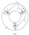
- the stator 5 has grooves 10 (see FIG. 2) , in which two electrical winding bars 1, 2 are arranged as components of the electrical winding.
- Each winding bar 1, 2 has a straight segment 1, which lies in the slot 10, and two arches 2, one at each end of the straight segment 1.
- the arches 2 run outside the slot 10 and serve to connect different winding bars to one another. Between the straight segments 1 there is one Intermediate layer 11 made of insulating material.
- a temperature sensor 3, 4 with a sensor element 3, in particular a resistance element with a temperature-dependent electrical resistance, and connecting lines 4 which lead out of the stator 5 and to be connected to signal processing devices for evaluating the temperature signals and error signals are.
- These signal processing devices are not shown in FIG. 1.
- the two temperature sensors 3, 4 can be used to locate damage 15, on which sparking occurs during operation of the large electrical machine, for example as part of a partial discharge. Because the damage 15 is much closer to the temperature sensor 3, 4 shown on the left than the one shown on the right, the error signal occurring in the left temperature sensor 3, 4 is significantly larger than the error signal which can be seen from the right temperature sensor 3, 4. This simple example shows how the damage 15 can be located.
- the location system for error signals thus present can advantageously be supplemented by further temperature sensors, in particular by temperature sensors approximately in the middle of the stator 5.
- FIG. 1 does not show all the usual features of a large electrical machine. So the stand 5 is shown as a compact block, which does not necessarily correspond to normal practice. Also not shown are means for closing the slots in which the winding bars 1, 2 are located. Furthermore, the proportions shown are not to scale. To supplement the information that can be gathered from FIG. 1 and the subsequent figures, reference is made to the general specialist knowledge of the relevant average specialist.
- Fig. 2 shows a cross section perpendicular to the axis through the machine shown in Fig. 1.
- the stand 5 has grooves 10, in which the straight segments 1 of the winding bars 1, 2 are inserted.
- Three grooves 10 are shown as representatives for the grooves 10 that are usually present in large numbers in large electrical machines.
- In each groove 10 there are two straight segments 1 one above the other, and an intermediate layer 11 is inserted between them.
- a sensor element 3 is located in each intermediate layer 11 with connecting lines 4.
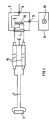
- 3 and 4 show two exemplary embodiments for temperature sensors which can be used as antennas and which are made up of sensor elements 3, in particular resistance elements with temperature-variable electrical resistances, connecting lines 4 and diplexers 6 for decoupling the error signals from the temperature signals.
- the connecting lines 4 are connected to a coaxial cable 16, namely a connecting line 4 to the inner conductor and another connecting line 4 to the outer conductor, which in turn is grounded.
- the mixture of temperature signal and error signal obtained by the temperature sensor is fed from the coaxial cable 16 to the input 7 of a diplexer 6.
- the error signal is decoupled from the temperature signal in the diplexer 6.
- the temperature signal is fed from the input 7 via a coil 18, which forms a low-pass filter for passing signals with low frequencies, to the first output 8 of the diplexer 6, and the error signal passes from the input 7 via a capacitor 17 to the second output 9 of the diplexer 6
- the capacitor 17 forms a high-pass filter which only allows high-frequency signals to pass through.
- the error signal can be fed from the second output 9 of the diplexer 6 to an evaluation device (not shown).
- the exact function of the temperature sensor formed from sensor element 3 and connecting lines 4 as an antenna for the high-frequency error signal depends, of course, essentially on the frequency of the error signal and the geometric dimensions of the temperature sensor; 3, however, a capacitive coupling to a high-frequency electromagnetic field in the large electrical machine is essentially achieved.
- Fig. 4 shows another embodiment of the temperature sensor, in which the connecting lines 4 with the sensor element 3 essentially serve as an inductively acting antenna for high-frequency signals.
- the temperature sensor is connected to two coaxial cables 16 with earthed outer conductors; the connecting lines 4 are connected to the inner conductor of the coaxial cable 16.
- the input 7 of the diplexer 6 is designed to connect both coaxial cables 16.
- the decoupling of the error signal from the temperature signal takes place by means of a transformer 19.
- the primary winding of the transformer 19, which is connected to the input 7, has a center tap or is bifilar wound, a connection corresponding to a center tap being provided.
- the first output 8 for deriving the low-frequency temperature signal is connected to the center tap of the primary winding.
- the high-frequency error signal is passed on in the transformer 19 to the secondary winding and from there fed to the second output 9 of the diplexer 6.
- An evaluation device 14 is connected to the second output 9, which of course can contain further filters and in which the error signal can be evaluated.
- the type of evaluation corresponds to the requirements of the individual case; In particular, an evaluation with regard to faults in the electrical machine is possible.
- the evaluation device 14 is provided with a display element 20, for example shown as a lamp.
- the invention enables a high-frequency error signal to be decoupled from a high-frequency electromagnetic field in a large electrical machine in a particularly simple and reliable manner, and in particular permits the detection of damage with spark formation.
Abstract
Description
Die Erfindung betrifft die Auskopplung eines hochfrequenten Fehlersignals aus einem hochfrequenten elektromagnetischen Feld in einer elektrischen Großmaschine mit einem eine elektrische Wicklung tragenden Ständer.The invention relates to the decoupling of a high-frequency error signal from a high-frequency electromagnetic field in a large electrical machine with a stator carrying an electrical winding.
Die Erfindung bezieht sich dabei insbesondere auf die betriebliche Überwachung einer elektrischen Großmaschine, vor allem auf die Erkennung von Schäden. Im einzelnen wird Bezug genommen auf Schäden, die beim Betrieb in der elektrischen Großmaschine zu Funkenbildungen führen.The invention relates in particular to the operational monitoring of a large electrical machine, especially to the detection of damage. In particular, reference is made to damage which leads to spark formation when operating in the large electrical machine.
Unter elektrischen Großmaschinen werden im vorliegenden Zusammenhang insbesondere Großgeneratoren wie z. B. Turbogeneratoren verstanden, deren elektrische Leistungen 50 MVA und mehr betragen.Large electrical generators in the present context are particularly large generators such. B. understood turbogenerators, the electrical outputs are 50 MVA and more.
Die Erkennung von Schäden in Anlagen mit elektrischen Großmaschinen findet ein ständig wachsendes Interesse im Bestreben, die Verfügbarkeit der Anlagen zu erhöhen und Schäden möglichst frühzeitig, womöglich sogar vorausschauend und vorzugsweise während des regulären Betriebs, zu erkennen. Dabei ist auch von Bedeutung, daß digitale Rechenanlagen zur Auswertung der Signale aus komplexen Überwachungssystemen in zunehmendem Umfang kostengünstig zur Verfügung stehen.The detection of damage in plants with large electrical machines is becoming increasingly popular in the effort to increase the availability of the plants and to detect damage as early as possible, possibly even with foresight and preferably during regular operation. It is also important that digital computing systems for evaluating the signals from complex monitoring systems are increasingly available at low cost.
Verfahren und Vorrichtungen zur Erkennung eventuell auch Lokalisierung, von Schäden in elektrischen Anlagen, insbesondere in Anlagen mit elektrischen Großmaschinen, gehen hervor aus der DE-34 08 256 C2, der DE-35 26 149 A1, der DE-39 18 116 A1, der EP-0228 613 B1 und der EP 0241 764 B1. Aus diesen Schriften sind sowohl ganze Systeme zur Erkennung und Lokalisierung von Schäden in elektrischen Anlagen mit Auswertungen von hochfrequenten Fehlersignalen als auch Einzelheiten zur Auskopplung hochfrequenter Fehlersignale aus hochfrequenten Feldern in elektrischen Großmaschinen erkennbar. Das US-Patent 4,949,001 betrifft den Nachweis von Teilentladungen in dem Ständer einer dynamoelektrischen Großmaschine, insbesondere eines Turbogenerators. Patentgemäß wird auf den Ständer ein in Streifenleitertecnnik ausgebildeter und als Antenne zur Auskopplung eines hochfrequenten Fehlersignals dienender Meßwertaufnehmer nach Art eines Richtkopplers aufgelegt und über entsprechende Anschlußleitungen mit einer Auswerteeinrichtung verbunden. Durch Auswertung der Höhe und/oder des zeitlichen Verlaufs des Fehlersignals soll eine Lokalisierung der Stelle, von der das Fehlersignal ausgegangen ist, erfolgen. Auf den Inhalt aller zitierten Dokumente wird zur Vermeidung weiterer Wiederholungen an dieser Stelle ausdrücklich Bezug genommen.Methods and devices for detection, possibly also localization, Damages in electrical systems, in particular in systems with large electrical machines, result from DE-34 08 256 C2, DE-35 26 149 A1, DE-39 18 116 A1, EP-0228 613 B1 and EP 0241 764 B1. These documents can be used to identify entire systems for the detection and localization of damage in electrical systems with evaluations of high-frequency error signals, as well as details for decoupling high-frequency error signals from high-frequency fields in large electrical machines. US Pat. No. 4,949,001 relates to the detection of partial discharges in the stator of a large dynamoelectric machine, in particular a turbogenerator. According to the patent, a measuring transducer, designed in stripline technology and serving as an antenna for decoupling a high-frequency error signal, is placed on the stand in the manner of a directional coupler and connected to an evaluation device via corresponding connecting lines. The location from which the error signal originated should be localized by evaluating the level and / or the time profile of the error signal. To avoid further repetition, reference is expressly made here to the content of all cited documents.
Ein wichtiger Gesichtspunkt bei der Auskopplung hochfrequenter Fehlersignale aus einer elektrischen Großmaschine ist die bestmögliche Ausnutzung ohnehin vorhandener Bauteile und Einrichtungen, um die von Fehlern oder dgl. verursachten hochfrequenten elektromagnetischen Felder nicht durch zusätzliche Bauteile zu beeinträchtigen oder gar abzuschirmen; darüber hinaus sind auch ökonomische Gesichtspunkte zu beachten, die allzu komplexe Systeme von Sensoren unvorteilhaft erscheinen lassen können. Schließlich sprechen auch Erwägungen zur Belastbarkeit und zum Wirkungsgrad der elektrischen Großmaschinen gegen eine allzu großzügige Gewährung von Platz für Systeme zur Betriebsüberwachung.An important aspect when decoupling high-frequency error signals from a large electrical machine is the best possible use of already existing components and devices so that the high-frequency electromagnetic fields caused by errors or the like are not impaired or even shielded by additional components; In addition, economic aspects must also be taken into account, which can make overly complex systems of sensors appear disadvantageous. Finally, considerations regarding the resilience and the efficiency of large electrical machines also speak against an overly generous granting of space for systems for operational monitoring.
Aus dem Aufsatz "Messen und Überwachen von Temperaturen an großen Asynchronmotoren" von W. Raasch, Elektro-Jahr 1979, Vogel-Verlag, Würzburg, DE, Seiten 27 bis 30, geht eine elektrische Großmaschine in Form eines Asynchronmotors hervor mit einem eine elektrische Wicklung tragenden Ständer, wobei die Wicklung in Nuten des Ständers eingelegt ist und wobei in einer Nut ein Temperaturmeßfühler angeordnet ist.From the article "Measuring and monitoring temperatures on large asynchronous motors" by W. Raasch, Elektro-Jahr 1979, Vogel-Verlag, Würzburg, DE, pages 27 to 30, a large electrical machine in the form of an asynchronous motor emerges with an electrical winding load-bearing stand, wherein the winding is inserted in the slots of the stand and wherein a temperature sensor is arranged in a groove.
Die Erfindung basiert auf der Aufgabe, eine Möglichkeit zur Auskopplung eines hochfrequenten Fehlersignals aus einer elektrischen Großmaschine anzugeben, bei der weitestgehend ausschließlich auf ohnehin vorhandene Einrichtungen zurückgegriffen wird. Es sollen hierzu sowohl Verfahren als auch Vorrichtungen angegeben werden.The invention is based on the object specify a possibility for decoupling a high-frequency error signal from a large electrical machine, in which largely only devices that are already available are used. Both methods and devices are to be specified for this purpose.
Das erfindungsgemäße Verfahren zur Auskopplung eines hochfrequenten Fehlersignals aus einem hochfrequenten elektromagnetischen Feld in einer elektrischen Großmaschine mit einem eine elektrische Wicklung tragenden und mit zumindest einem Temperaturfühler bestückten Ständer beruht darauf, daß der Temperaturfühler als Antenne zur Auskopplung des Fehlersignals benutzt wird.The inventive method for decoupling a high-frequency error signal from a high-frequency electromagnetic field in a large electrical machine with a stand carrying an electrical winding and equipped with at least one temperature sensor is based on the fact that the temperature sensor is used as an antenna for decoupling the error signal.
Erfindungsgemäß wird zur Auskopplung des hochfrequenten Fehlersignals auf eine in der Regel ohnehin vorhandene Überwachungseinrichtung, nämlich eine Überwachungseinrichtung für die Betriebstemperatur mit zumindest einem Temperaturfühler, zurückgegriffen. Auf die spezielle Art des Temperaturfühlers kommt es dabei nur insoweit an, als daß dieser Temperaturfühler als Antenne für hochfrequente Signale geeignet sein muß. Dies bedeutet vor allem, daß er zumindest teilweise eine hinreichende elektrische Leitfähigkeit sowie nicht allzu kleine Abmessungen aufweisen sollte. Dies ist allerdings bei den Üblicherweise eingesetzten Temperaturfühlern der Fall. Vielfach werden nämlich Temperaturfühler mit temperaturabhängigen elektrischen Widerständen benutzt, die mit immerhin viele Zentimeter langen Anschlußleitungen versehen sind; auch kommen ohne weiteres sämtliche Temperaturfühler in Frage, die metallische Hüllrohre oder ähnliche Bauteile haben und ansonsten in nahezu beliebiger Weise zu betreiben sein können. Temperaturfühler sind auch deshalb besonders vorteilhaft, weil sie in einem Ständer einer elektrischen Großmaschine stets in der Nähe der (erhöhte Temperaturen erzeugenden) elektrischen Wicklung angeordnet sind, also in der Nähe des für Funkenbildungen kritischsten Teils. Dementsprechend ist auch die Stärke der einem üblichen Temperaturfühler abnehmbaren hochfrequenten Signale kein Problem, da durch die Nähe zu den möglichen Fehlerquellen in aller Regel ein recht starkes hochfrequentes elektromagnetisches Feld in der Umgebung des Temperaturfühlers und damit eine hinreichende Stärke des mittels des Temperaturfühlers erhaltenen Fehlersignals gewährleistet ist. Darüber hinaus ist jedenfalls die von einem Temperaturfühler gemessene Temperatur in einer elektrischen Großmaschine eine zeitlich nur sehr wenig veränderliche Größe, die von einem sehr niederfrequenten Signal, praktisch einem Signal der Frequenz Null, darstellbar ist und somit eine problemlose Trennung zwischen Temperatursignalen und hochfrequenten Fehlersignalen erlaubt.According to the invention, a monitoring device that is generally present anyway, namely a monitoring device for the operating temperature with at least one temperature sensor, is used to decouple the high-frequency error signal. The special type of temperature sensor is only important insofar as this temperature sensor must be suitable as an antenna for high-frequency signals. Above all, this means that it should at least partially have sufficient electrical conductivity and not too small dimensions. However, this is the case with the temperature sensors commonly used. In many cases, temperature sensors with temperature-dependent electrical resistors are used, which are provided with connecting cables that are at least many centimeters long; all temperature sensors which have metallic cladding tubes or similar components and which can otherwise be operated in almost any manner are also possible. Temperature sensors are also particularly advantageous because they are always close to the (elevated temperatures generating) electrical winding are arranged, so in the vicinity of the most critical part for sparking. Accordingly, the strength of the high-frequency signals which can be removed from a conventional temperature sensor is not a problem, since the proximity to the possible sources of error generally ensures a very strong high-frequency electromagnetic field in the vicinity of the temperature sensor and thus a sufficient strength of the error signal obtained by means of the temperature sensor . In addition, the temperature measured by a temperature sensor in a large electrical machine is a variable that changes very little over time, which can be represented by a very low-frequency signal, practically a signal of zero frequency, and thus allows a problem-free separation between temperature signals and high-frequency error signals.
Daß günstigerweise im Rahmen der Erfindung elektrisch betriebene Temperaturfühler eingesetzt werden, insbesondere Temperaturfühler, die mit elektrischer Gleichspannung oder elektrischem Gleichstrom betrieben werden, wurde bereits erwähnt. Besonders geeignet ist ein Temperaturfühler, der ein in dem Ständer der elektrischen Großmaschine liegendes Fühlerelement mit daran angeschlossenen, aus dem Ständer herausführenden Anschlußleitungen aufweist. Bei einem solchen Temperaturfühler können die Anschlußleitungen unmittelbar als Antennen wirken, insbesondere als Viertelwellenantennen. Auch können mit einem solchen Temperaturfühler hochfrequente Fehlersignale gewonnen werden, welche durch das der Gewinnung der Temperatursignale dienende Fühlerelement nicht beeinflußt sind. Beispielsweise führen von dem Fühlerelement zwei miteinander verdrillte elektrische Anschlußleitungen ab, die zur Ableitung der hochfrequenten Fehlersignale gleichphasig angezapft werden. Dann wirken die Anschlußleitungen wie eine einzige Antenne, und das Fühlerelement trägt je nach Ausgestaltung überhaupt nicht oder nur sehr wenig zu den Fehlersignalen bei. Keinen Beitrag ergäbe beispielsweise ein Fühlerelement, das lediglich ein räumlich kleines Widerstandselement mit temperaturabhängigem elektrischem Widerstand ist. In jedem Falle ist es vorteilhaft, die Fehlersignale gleichzeitig mit den Temperatursignalen von dem Temperaturfühler abzunehmen und nachfolgend von diesen zu entkoppeln. Dies ist besonders einfach dann möglich, wenn die Temperatursignale niederfrequente Signale, insbesondere Gleichstromsignale oder Gleichspannungssignale, sind.It has already been mentioned that it is advantageous to use electrically operated temperature sensors in the context of the invention, in particular temperature sensors that are operated with direct electrical voltage or direct current. A temperature sensor is particularly suitable which has a sensor element located in the stator of the large electrical machine with connected connecting leads leading out of the stator. With such a temperature sensor, the connecting lines can act directly as antennas, in particular as quarter-wave antennas. Such a temperature sensor can also be used to obtain high-frequency error signals which are not influenced by the sensor element used to obtain the temperature signals. For example, lead from the sensor element two twisted electrical connection lines, which are tapped in phase to derive the high-frequency error signals. Then the connecting lines act as one Antenna, and depending on the configuration, the sensor element does not contribute at all or only very little to the error signals. For example, there would be no contribution from a sensor element, which is merely a spatially small resistance element with temperature-dependent electrical resistance. In any case, it is advantageous to take the error signals from the temperature sensor at the same time as the temperature signals and to subsequently decouple them. This is particularly easy if the temperature signals are low-frequency signals, in particular direct current signals or direct voltage signals.
Eine besonders günstige Weiterbildung des erfindungsgemäßen Verfahrens ist dadurch gekennzeichnet, daß in einer Vielzahl in der elektrischen Großmaschine vorhandene Temperaturfühler als Antennen benutzt werden. Vorteilhafterweise sind die vielzähligen Temperaturfühler im wesentlichen gleichmäßig über den Ständer verteilt, so daß die Fehlersignale der Temperaturfühler zueinander korreliert werden können zur Ermittlung einer Stelle in der Großmaschine, wo sie verursacht wurden. Diese Ausgestaltung macht vorteilhaften Gebrauch von der Tatsache, daß hochfrequente elektromagnetische Felder in einer elektrischen Großmaschine bei ihrer Ausbreitung beträchtlich gedämpft werden, so daß die mit den von einer bestimmten Stelle ausgehenden hochfrequenten Feldern erhaltbaren Fehlersignale bezüglich ihrer Stärke wesentlich von der Positionierung eines zur Auskopplung benutzten Temperaturfühlers abhängen. Mit einer hinreichenden Vielzahl von Temperaturfühlern kann daher aus einer Bewertung der Stärken (und unter Umständen auch der Phasenlagen) der erhaltenen Fehiersignale auf die Stelle geschlossen werden, wo die Fehlersignale verursacht wurden.A particularly advantageous development of the method according to the invention is characterized in that a large number of temperature sensors present in the large electrical machine are used as antennas. Advantageously, the numerous temperature sensors are distributed substantially uniformly over the stand, so that the error signals of the temperature sensors can be correlated to one another to determine a location in the large machine where they were caused. This configuration makes advantageous use of the fact that high-frequency electromagnetic fields in a large electrical machine are considerably attenuated as they spread, so that the strength of the error signals that can be obtained with the high-frequency fields emanating from a specific location is essentially dependent on the positioning of a temperature sensor used for decoupling depend. With a sufficient number of temperature sensors, an evaluation of the strengths (and possibly also the phase positions) of the error signals obtained can be used to conclude where the error signals were caused.
Die erfindungsgemäße Vorrichtung zur Auskopplung eines hochfrequenten Fehlersignals aus einem hochfrequenten elektromagnetischen Feld in einer elektrischen Großmaschine mit einem eine elektrische Wicklung tragenden Ständer ist ausgezeichnet durch zumindest einen in dem Ständer angeordneten Temperaturfühler zur Erzeugung eines niederfrequenten Temperatursignals, mit Anschlußleitungen, die aus dem Ständer herausführen, und einen Diplexer zur Entkopplung des Fehlersignals von dem Temperatursignal, mit einem Eingang, einem ersten Ausgang und einem zweiten Ausgang, an welchem Eingang die Anschlußleitungen angeschlossen sind, an welchem ersten Ausgang das Temperatursignal und an welchem zweiten Ausgang das Fehlersignal bereitgestellt wird.The device according to the invention for decoupling a high-frequency error signal from a high-frequency electromagnetic field in a large electrical machine with a stator carrying an electrical winding is distinguished by at least one temperature sensor arranged in the stator for generating a low-frequency temperature signal, with connecting leads which lead out of the stator, and a diplexer for decoupling the error signal from the temperature signal, with an input, a first output and a second output, to which input the connecting lines are connected, to which first output the temperature signal and to which second output the error signal is provided.
Die erfindungsgemäße Vorrichtung stellt ein Fehlersignal bereit, welches von einem in dem Ständer angeordneten Temperaturfühler abgenommen und von einem ebenfalls dem Temperaturfühler entstammenden Temperatursignal entkoppelt ist. Wie bereits angedeutet, ist der Temperaturfühler vorzugsweise elektrisch betreibbar und liefert als Temperatursignal ein niederfrequentes Signal, vorzugsweise ein Gleichstromsignal; in diesem Fall ist der Diplexer günstigerweise so ausgestattet, daß er bezüglich des ersten Ausgangs als Tiefpaßfilter und bezüglich des zweiten Ausgangs als Hochpaßfilter wirkt. Dies bedeutet, daß der Diplexer ein am Eingang eingespeistes niederfrequentes Signal dem ersten Ausgang und ein am Eingang eingespeistes hochfrequentes Signal dem zweiten Ausgang zustellt. Es versteht sich, daß den Ausgängen des Diplexers ggf. weiter Filter, insbesondere Hochpaß-, Tiefpaß- oder Bandpaßfilter, nachgeschaltet sein können. Auch können Verstärker und andere Signalverarbeitungseinrichtungen selbstverständlich einbezogen sein.The device according to the invention provides an error signal which is picked up by a temperature sensor arranged in the stator and is decoupled from a temperature signal likewise originating from the temperature sensor. As already indicated, the temperature sensor can preferably be operated electrically and supplies a low-frequency signal, preferably a direct current signal, as the temperature signal; in this case the diplexer is advantageously equipped so that it acts as a low-pass filter with respect to the first output and as a high-pass filter with respect to the second output. This means that the diplexer delivers a low-frequency signal fed in at the input to the first output and a high-frequency signal fed in at the input to the second output. It goes without saying that further filters, in particular high-pass, low-pass or band-pass filters, can optionally be connected downstream of the outputs of the diplexer. Amplifiers and other signal processing devices can of course also be included.
Der Temperaturfühler der Vorrichtung liegt vorzugsweise in einer Nut, welche zu einer Vielzahl von Nuten des Ständers gehört, in welche Wicklungsstäbe der Wicklung eingelegt sind. Auf diese Weise ist der Temperaturfühler der Wicklung, an welcher Funkenbildungen und dergleichen in erster Linie auftreten können, unmittelbar benachbart, wodurch ein recht starkes hochfrequentes elektromagnetisches Feld in der Umgebung des Temperaturfühlers und damit eine hinreichende Stärke der von dem Temperaturfühler abzunehmenden Fehlersignale gewährleistet ist. Besonders bevorzugt ist es dabei, daß der Temperaturfühler in einer elektrisch isolierenden Zwischenlage, die in einer Nut zwischen zwei in der Nut übereinanderliegenden Wicklungsstäben angeordnet ist, liegt. Auf diese Weise ist der Temperaturfühler empfindlich für hochfrequente elektromagnetische Felder, die von beiden Wicklungsstäben in der Nut ausgehen, und er befindet sich in einer elektrisch isolierenden Schicht, in der die Ausbreitung hochfrequenter elektromagnetischer Felder relativ gut möglich ist.The temperature sensor of the device preferably lies in a slot which belongs to a plurality of slots in the stator, in which winding bars of the winding are inserted. In this way, the temperature sensor of the winding, on which sparking and the like can occur primarily, is immediately adjacent, which ensures a very strong high-frequency electromagnetic field in the vicinity of the temperature sensor and thus a sufficient strength of the error signals to be taken from the temperature sensor. It is particularly preferred that the temperature sensor is located in an electrically insulating intermediate layer which is arranged in a slot between two winding bars lying one above the other in the slot. In this way, the temperature sensor is sensitive to high-frequency electromagnetic fields emanating from both winding bars in the slot, and it is located in an electrically insulating layer in which the propagation of high-frequency electromagnetic fields is relatively possible.
Günstig ist auch, wenn der Temperaturfühler als eigentliches Fühlerelement zur Bildung der Temperatursignale ein Widerstandselement mit einem temperaturabhängigen elektrischen Widerstand aufweist.It is also advantageous if the temperature sensor as the actual sensor element for forming the temperature signals has a resistance element with a temperature-dependent electrical resistance.
Besonders günstig ist es, wenn in der Vorrichtung eine Vielzahl von Temperaturfühlern zur Lieferung von Temperatursignalen und Fehlersignalen vorgesehen sind, wobei die Temperaturfühler vorzugsweise gleichmäßig über den Ständer verteilt sind.It is particularly expedient if a plurality of temperature sensors for supplying temperature signals and error signals are provided in the device, the temperature sensors preferably being distributed uniformly over the stand.
Die Erfindung ermöglicht in besonders günstiger Weise den Nachweis einer Funkenbildung in einer elektrischen Großmaschine, wobei aus dem Auftreten eines hochfrequenten Fehlersignals an einem Temperaturfühler auf eine Funkenbildung geschlossen wird. Insbesondere ermöglicht die Erfindung eine besonders günstige Erkennung und, im Rahmen einer Weiterbildung Lokalisierung eines Schadens.The invention enables the detection of spark formation in a large electrical machine in a particularly advantageous manner, spark formation being concluded from the occurrence of a high-frequency error signal at a temperature sensor. In particular, the invention enables particularly favorable detection and, in the context of a further development, localization of damage.
Ein erfindungsgemäß auszukoppelndes hochfrequentes Fehlersignal liegt vorteilhafterweise in einem Frequenzbereich zwischen 1 MHz und 300 MHz, insbesondere zwischen 3 MHz und 100 MHz. Zum Nachweis von hochfrequenten Fehlersignalen mit solchen Frequenzen sind Temperaturfühler mit üblichen geometrischen Abmessungen besonders geeignet.A high-frequency error signal to be decoupled according to the invention is advantageously in a frequency range between 1 MHz and 300 MHz, in particular between 3 MHz and 100 MHz. For the detection of high-frequency error signals with such frequencies, temperature sensors with the usual geometric dimensions are particularly suitable.
Ausführungsbeispiele der Erfindung werden nun anhand der Zeichnung erläutert. Zur Verdeutlichung bestimmter Merkmale ist die Zeichnung teilweise schematisiert und/oder nicht maßstäblich ausgeführt. Insbesondere wurde teilweise auf die Darstellung einschlägig bekannter und im vorliegenden Zusammenhang nicht wesentlicher Komponenten verzichtet. Im einzelnen zeigen:
- Fig. 1 einen schematisierten axialen Längsschnitt durch eine elektrische Großmaschine mit erfindungsgemäß zu benutzenden Temperaturfühlern;
- Fig. 2 einen schematisierten radialen Querschnitt durch die in Fig. 1 dargestellte Maschine;
- Fig. 3 und Fig. 4 Ausführungsbeispiele für im Sinne der Erfindung ertüchtigte Temperaturfühler.
- 1 shows a schematic axial longitudinal section through a large electrical machine with temperature sensors to be used according to the invention;
- FIG. 2 shows a schematic radial cross section through the machine shown in FIG. 1;
- 3 and 4 show exemplary embodiments of temperature sensors that have been upgraded in the sense of the invention.
Fig. 1 zeigt einen entlang der Achse 13 ausgeführten Längsschnitt durch eine elektrische Großmaschine mit einem Ständer 5 und einem in einer Ausnehmung des Ständers 5 angeordneten, um die Achse 13 drehbaren Rotor 12. Der Ständer 5 weist Nuten 10 auf (siehe Fig. 2), in denen zwei elektrische Wicklungsstäbe 1, 2 als Bestandteile der elektrischen Wicklung angeordnet sind. Jeder Wicklungsstab 1, 2 hat ein gerades Segment 1, welches in der Nut 10 liegt, sowie zwei Bögen 2, jeweils einen an jedem Ende des geraden Segmentes 1. Die Bögen 2 verlaufen außerhalb der Nut 10 und dienen der Verbindung verschiedener Wicklungsstäbe miteinander. Zwischen den geraden Segmenten 1 liegt eine Zwischenlage 11 aus isolierendem Material. An jedem Ende des Ständers 5 liegt in der Zwischenlage 11 ein Temperaturfühler 3, 4 mit einem Fühlerelement 3, insbesondere einem Widerstandselement mit einem temperaturabhängigen elektrischen Widerstand, und Anschlußleitungen 4, welche aus dem Ständer 5 herausführen und an Signalverarbeitungseinrichtungen zur Auswertung der Temperatursignale und Fehlersignale anzuschließen sind. Diese Signalverarbeitungseinrichtungen sind in Fig. 1 nicht dargestellt. Die zwei Temperaturfühler 3, 4 können herangezogen werden zur Ortung eines Schadens 15, an dem beim Betrieb der elektrischen Großmaschine eine Funkenbildung, beispielsweise im Rahmen einer Teilentladung, auftritt. Dadurch, daß der Schaden 15 dem links dargestellten Temperaturfühler 3, 4 wesentlich näher ist als dem rechts dargestellten, ist das im linken Temperaturfühler 3, 4 auftretende Fehlersignal wesentlich größer als das Fehlersignal, welches dem rechten Temperaturfühler 3, 4 entnehmbar ist. Aus diesem einfachen Beispiel ist ersichtlich, wie eine Ortung des Schadens 15 möglich ist. Das somit vorliegende Ortungssystem für Fehlersignale ist vorteilhaft ergänzbar um weitere Temperaturfühler, insbesondere um Temperaturfühler etwa in der Mitte des Ständers 5.1 shows a longitudinal section along the
Es sei nochmals darauf hingewiesen, daß Fig. 1 nicht alle üblichen Merkmale einer elektrischen Großmaschine zeigt. So ist der Ständer 5 dargestellt als kompakter Block, was nicht unbedingt der üblichen Praxis entspricht. Auch sind nicht dargestellt Mittel zum Verschließen der Nuten, in denen die Wicklungsstäbe 1, 2 liegen. Weiterhin sind die dargestellten Größenverhältnisse nicht maßstabsgerecht. Für eine Ergänzung der aus Fig. 1 und den nachfolgenden Figuren entnehmbaren Hinweise wird insoweit auf das allgemeine Fachwissen des einschlägig tätigen Durchschnittfachmanns verwiesen.It should be pointed out again that FIG. 1 does not show all the usual features of a large electrical machine. So the
Fig. 2 zeigt einen senkrecht zur Achse gelegten Querschnitt durch die in Fig. 1 dargestellte Maschine. Der Ständer 5 weist Nuten 10 auf, in die die geraden Segmente 1 der Wicklungsstäbe 1, 2 eingelegt sind. Dargestellt sind drei Nuten 10 als Repräsentanten für die üblicherweise in elektrischen Großmaschinen in großer Vielzahl vorhandenen Nuten 10. In jeder Nut 10 befinden sich übereinander zwei gerade Segmente 1, und zwischen diesen eingefügt ist eine Zwischenlage 11. In jeder Zwischenlage 11 befindet sich ein Fühlerelement 3 mit Anschlußleitungen 4.Fig. 2 shows a cross section perpendicular to the axis through the machine shown in Fig. 1. The
Die Fig. 3 und 4 zeigen zwei Ausführungsbeispiele für als Antennen benutzbare Temperaturfühler aus Fühlerelementen 3, insbesondere Widerstandselementen mit temperaturveränderlichen elektrischen Widerständen, Anschlußleitungen 4 und Diplexern 6 zur Entkopplung der Fehlersignale von den Temperatursignalen. Gemäß Fig. 3 sind die Anschlußleitungen 4 an ein Koaxialkabel 16 angeschlossen, und zwar eine Anschlußleitung 4 an den Innenleiter und eine andere Anschlußleitung 4 an den Außenleiter, der seinerseits geerdet ist. Aus dem Koaxialkabel 16 wird das von dem Temperaturfühler erhaltene Gemisch aus Temperatursignal und Fehlersignal dem Eingang 7 eines Diplexers 6 zugeführt. In dem Diplexer 6 erfolgt die Entkopplung des Fehlersignals von dem Temperatursignal. Das Temperatursignal wird vom Eingang 7 über eine Spule 18, welche ein Tiefpaßfilter zum Durchlaß von Signalen mit niedrigen Frequenzen bildet, dem ersten Ausgang 8 des Diplexers 6 zugeführt, und das Fehlersignal gelangt vom Eingang 7 über einen Kondensator 17 zum zweiten Ausgang 9 des Diplexers 6. Der Kondensator 17 bildet ein Hochpaßfilter, welches nur hochfrequente Signale passieren läßt. Vom zweiten Ausgang 9 des Diplexers 6 ist das Fehlersignal einer nicht dargestellten Auswerteeinrichtung zuführbar. Die genaue Funktion des aus Fühlerelement 3 und Anschlußleitungen 4 gebildeten Temperaturfühlers als Antenne für das hochfrequente Fehlersignal hängt natürlich wesentlich von der Frequenz des Fehlersignals und den geometrischen Abmessungen des Temperaturfühlers ab; mit dem Temperaturfühler nach Fig. 3 wird jedoch im wesentlichen eine kapazitive Kopplung an ein hochfrequentes elektromagnetisches Feld in der elektrischen Großmaschine erreicht.3 and 4 show two exemplary embodiments for temperature sensors which can be used as antennas and which are made up of
Fig. 4 zeigt eine andere Ausgestaltung des Temperaturfühlers, bei dem die Anschlußleitungen 4 mit dem Fühlerelement 3 im wesentlichen als eine induktiv wirkende Antenne für hochfrequente Signale dienen. Nach Fig. 4 ist der Temperaturfühler angeschlossen an zwei Koaxialkabel 16 mit geerdeten Außenleitern; die Anschlußleitungen 4 sind an die Innenleiter der Koaxialkabel 16 angeschlossen. Der Eingang 7 des Diplexers 6 ist ausgebildet zum Anschluß beider Koaxialkabel 16. Die Entkopplung des Fehlersignals von dem Temperatursignal erfolgt mittels eines Transformators 19. Die Primärwicklung des Transformators 19, die mit dem Eingang 7 verbunden ist, weist eine Mittenanzapfung auf oder ist bifilar gewickelt, wobei ein einer Mittenanzapfung entsprechender Anschluß vorgesehen ist. An die Mittenanzapfung der Primärwicklung angeschlossen ist der erste Ausgang 8 zur Ableitung des niederfrequenten Temperatursignals. Das hochfrequente Fehlersignal wird in dem Transformator 19 an die Sekundärwicklung weitergegeben und von dort dem zweiten Ausgang 9 des Diplexers 6 zugeführt. An den zweiten Ausgang 9 angeschlossen ist eine Auswerteeinrichtung 14, welche selbstverständlich weitere Filter beinhalten kann und in der das Fehlersignal auswertbar ist. Die Art und Weise der Auswertung entspricht den Anforderungen des Einzelfalls; insbesondere möglich ist eine Auswertung im Hinblick auf Störungen in der elektrischen Maschine. Zur Anzeige solcher Störungen ist die Auswerteeinrichtung 14 versehen mit einem Anzeigeelement 20, beispielhaft als Lampe dargestellt.Fig. 4 shows another embodiment of the temperature sensor, in which the connecting
Die Erfindung ermöglicht in besonders einfacher und zuverlässiger Weise die Auskopplung eines hochfrequenten Fehlersignals aus einem hochfrequenten elektromagnetischen Feld in einer elektrischen Großmaschine und gestattet insbesondere die Erkennung eines Schadens mit Funkenbildung.The invention enables a high-frequency error signal to be decoupled from a high-frequency electromagnetic field in a large electrical machine in a particularly simple and reliable manner, and in particular permits the detection of damage with spark formation.
Claims (17)
- Method for decoupling a high-frequency error signal originating from a high-frequency electromagnetic field in a heavy electrical machine having a stator (5) which carries an electrical winding (1, 2), characterized in that the stator (5) is equipped with at least one temperature sensor (3, 4) and said temperature sensor (3, 4) is utilized as aerial for decoupling the error signal.
- Method according to Claim 1, wherein the temperature sensor (3, 4) for obtaining a temperature signal is electrically operated.
- Method according to Claim 2, wherein the temperature sensor (3, 4) for obtaining the temperature signal is supplied with electrical direct voltage or electrical direct current.
- Method according to Claim 2 or 3, wherein the temperature sensor (3, 4) comprises a sensor element (3) situated in the stator (5) and having connecting leads (4) connected thereto and leading out of the stator (5).
- Method according to one of Claims 2 to 4, wherein the error signal is picked up from the temperature sensor (3, 4) at the same time as the temperature signal and is decoupled from the temperature signal.
- Method according to Claim 5, wherein the temperature signal is a low-frequency signal, in particular a direct-current signal.
- Method according to one of the preceding claims, wherein error signals are picked up from a multiplicity of temperature sensors (3, 4).
- Method according to Claim 7, whereina) the temperature sensors (3, 4) are distributed essentially uniformly over the stator (5);b) the error signals of the temperature sensors (3, 4) are correlated with one another to determine a position (15) in the heavy machine at which the error signal was caused.
- Method according to one of Claims 1 to 8, wherein the spark formation is inferred from the occurrence of a high-frequency error signal to detect a spark formation in the heavy electrical machine.
- Method according to one of Claims 1 to 8, wherein a defect in the heavy electrical machine is inferred from the occurrence of the error signal.
- Method according to one of Claims 1 to 8, wherein an error signal having a frequency between 1 MHz and 300 MHz, in particular between 3 MHz and 100 MHz, is decoupled.
- Device for decoupling a high-frequency error signal originating from a high-frequency electromagnetic field in a heavy electrical machine having a stator (5) which carries an electrical winding (1, 2), characterized by at least one temperature sensor (3, 4) disposed in the stator (5) for generating a low-frequency temperature signal and having connecting leads (4) which lead out of the stator (5), and by a diplexer (6) for decoupling the error signal from the temperature signal, having an input (7), a first output (8) and a second output (9), to which input (7) the connecting leads (4) are connected, at which first output (8) the temperature signal is provided and at which second output (9) the error signal is provided.
- Device according to Claim 12, whereina) the temperature sensor (3, 4) is electrically operated;b) the diplexer (6) acts as a low-pass filter in relation to the first output (8) and as a high-pass filter in relation to the second output (9).
- Device according to Claim 12 or 13, wherein the temperature sensor (3, 4) is situated in a slot (10) which belongs to a multiplicity of slots (10) in the stator (5) in which winding bars (1) of the winding (1, 2) are laid.
- Device according to Claim 14, wherein the temperature sensor (3, 4) is situated in an electrically insulating interlayer (11) which is disposed in a slot (10) between two winding bars (1) situated one on top of the other in the slot (10).
- Device according to one of Claims 12 to 15, wherein the temperature sensor (3, 4) has a resistance element (3) comprising a temperature-dependent electrical resistor.
- Device according to one of Claims 12 to 16, which has a multiplicity of temperature sensors (3, 4) which are distributed preferably uniformly over the stator (5).
Applications Claiming Priority (3)
| Application Number | Priority Date | Filing Date | Title |
|---|---|---|---|
| DE4231714 | 1992-09-22 | ||
| DE4231714 | 1992-09-22 | ||
| PCT/DE1993/000815 WO1994007152A1 (en) | 1992-09-22 | 1993-09-07 | Decoupling of a high-frequency error signal from a high-frequency electromagnetic field in a large electric machine |
Publications (2)
| Publication Number | Publication Date |
|---|---|
| EP0662220A1 EP0662220A1 (en) | 1995-07-12 |
| EP0662220B1 true EP0662220B1 (en) | 1996-11-20 |
Family
ID=6468552
Family Applications (1)
| Application Number | Title | Priority Date | Filing Date |
|---|---|---|---|
| EP93918952A Expired - Lifetime EP0662220B1 (en) | 1992-09-22 | 1993-09-07 | Decoupling of a high-frequency error signal from a high-frequency electromagnetic field in a large electric machine |
Country Status (11)
| Country | Link |
|---|---|
| US (1) | US5917334A (en) |
| EP (1) | EP0662220B1 (en) |
| JP (1) | JPH08501389A (en) |
| KR (1) | KR100306084B1 (en) |
| CN (1) | CN1044746C (en) |
| AT (1) | ATE145482T1 (en) |
| CZ (1) | CZ284614B6 (en) |
| DE (1) | DE59304558D1 (en) |
| ES (1) | ES2095664T3 (en) |
| RU (1) | RU2129285C1 (en) |
| WO (1) | WO1994007152A1 (en) |
Cited By (2)
| Publication number | Priority date | Publication date | Assignee | Title |
|---|---|---|---|---|
| EP3570052A1 (en) | 2018-05-18 | 2019-11-20 | Siemens Aktiengesellschaft | Method for measurement of a pulsed high frequency event signal |
| EP3839531A1 (en) | 2019-12-16 | 2021-06-23 | Siemens Aktiengesellschaft | Device for detecting a high-frequency event signal in an electric rotating machine |
Families Citing this family (11)
| Publication number | Priority date | Publication date | Assignee | Title |
|---|---|---|---|---|
| JP3187642B2 (en) * | 1994-02-25 | 2001-07-11 | 関西電力株式会社 | Electrical device abnormality detection method and rotating electrical machine abnormality detection device |
| JP3685367B2 (en) * | 1999-05-24 | 2005-08-17 | 三菱電機株式会社 | Rotating electrical machine abnormality detection device |
| CA2467106A1 (en) * | 2001-11-19 | 2003-05-30 | Alstom (Switzerland) Ltd. | Method for dectection of a ground fault, which occurs in the vicinity of a neutral point in an electrical device, as well as an apparatus for carrying out the method |
| EP1418437A1 (en) * | 2002-10-02 | 2004-05-12 | ALSTOM Technology Ltd | Method and electromagnetic sensor for measuring partial discharges in windings of electrical devices |
| DE10318951B4 (en) * | 2003-04-26 | 2016-12-29 | Hella Kgaa Hueck & Co. | Device and method for detecting arcs in a circuit, in particular in a motor vehicle electrical system |
| DE102004020724B3 (en) * | 2004-04-28 | 2006-01-05 | Sensoplan Aktiengesellschaft | Method for detecting defects in sheet metal segments in electric generators and motors |
| DE102007061573A1 (en) * | 2007-12-18 | 2009-06-25 | Endress + Hauser Gmbh + Co. Kg | Device for determining and / or monitoring at least one level of at least one medium in a container according to a travel time measurement method and / or a capacitive measurement method |
| US8129873B2 (en) * | 2010-04-05 | 2012-03-06 | General Electronic Company | Stator coil coolant flow reduction monitoring |
| ITMI20111194A1 (en) * | 2011-06-29 | 2012-12-30 | Ansaldo Energia Spa | DEVICE AND METHOD TO PERFORM THERMAL RESISTANCE TESTS ON AT LEAST ONE STATHY BAR OF AN ELECTRIC MACHINE |
| US20220224261A1 (en) * | 2019-04-30 | 2022-07-14 | Brookhaven Science Associates, Llc | Method and device for detection of condition of brushless motors and generators |
| CZ309279B6 (en) | 2021-01-18 | 2022-07-13 | Modemtec S.R.O. | A method of signal extraction and a device for this |
Family Cites Families (17)
| Publication number | Priority date | Publication date | Assignee | Title |
|---|---|---|---|---|
| US3641439A (en) * | 1969-08-08 | 1972-02-08 | Narda Microwave Corp | Near-field radiation monitor |
| US4083001A (en) * | 1976-12-29 | 1978-04-04 | Westinghouse Electric Corporation | Measurement of motor winding temperature |
| US4114077A (en) * | 1977-04-01 | 1978-09-12 | Westinghouse Electric Corp. | Rotor overtemperature protection for electric motors |
| US4238733A (en) * | 1979-05-15 | 1980-12-09 | Canadian General Electric Company Limited | Corona discharge monitor system |
| DE3234023A1 (en) * | 1982-09-14 | 1984-03-15 | SWF-Spezialfabrik für Autozubehör Gustav Rau GmbH, 7120 Bietigheim-Bissingen | Device for monitoring the operating state of an electric motor |
| DD214461B1 (en) * | 1983-04-14 | 1989-09-27 | Meissen Kabelwerk | MEASURING PROBE FOR THE ELECTRICAL DETECTION OF IMPULSE SOFT PARTIAL DISCHARGES |
| CH673729A5 (en) * | 1984-10-04 | 1990-03-30 | Mitsubishi Electric Corp | |
| DE3526149A1 (en) * | 1985-06-15 | 1986-12-18 | Kraftwerk Union AG, 4330 Mülheim | CONNECTING UNIT FOR THE OPERATIONAL MONITORING OF THE HIGH VOLTAGE WINDINGS AND THE CONNECTED LEADS FOR ELECTRICAL HIGH VOLTAGE MACHINES AND APPARATUS, BY MEANS OF PARTIAL DISCHARGE DETECTION AND TAKE-OFF SPARK MEASUREMENT |
| DE3543927A1 (en) * | 1985-12-12 | 1987-06-19 | Kraftwerk Union Ag | METHOD FOR PARTIAL DISCHARGE DETECTION AND Tear-off Spark Measurement in DYNAMOELECTRIC HIGH-VOLTAGE MACHINES AND DEVICE FOR ITS IMPLEMENTATION |
| EP0241764B1 (en) * | 1986-04-14 | 1990-08-01 | Siemens Aktiengesellschaft | Process and devices for detecting and localizing damages in electrical installations |
| DE3918116A1 (en) * | 1989-06-02 | 1990-12-06 | Siemens Ag | Monitoring function of turbogenerator rectifier - indirectly sensing commutation performance and analytically locating individual faults on rotary rectifiers |
| US4949001A (en) * | 1989-07-21 | 1990-08-14 | Campbell Steven R | Partial discharge detection method and apparatus |
| US5019760A (en) * | 1989-12-07 | 1991-05-28 | Electric Power Research Institute | Thermal life indicator |
| US5262717A (en) * | 1991-04-16 | 1993-11-16 | Ontario Hydro | Method and apparatus for measuring electric motor efficiency and loading |
| US5257863A (en) * | 1992-07-30 | 1993-11-02 | Electric Power Research Institute, Inc | Electronic rotor temperature sensor |
| US5416430A (en) * | 1993-04-28 | 1995-05-16 | Electric Power Research Institute, Inc. | Apparatus and method for identification and location of internal arcing in dynamoelectric machines |
| US5475312A (en) * | 1994-06-07 | 1995-12-12 | Iris Power Engineering Inc. | Method and device for distinguishing between partial discharge and electrical noise |
-
1993
- 1993-09-07 DE DE59304558T patent/DE59304558D1/en not_active Expired - Fee Related
- 1993-09-07 JP JP6507657A patent/JPH08501389A/en active Pending
- 1993-09-07 EP EP93918952A patent/EP0662220B1/en not_active Expired - Lifetime
- 1993-09-07 RU RU95111380A patent/RU2129285C1/en active
- 1993-09-07 KR KR1019950701110A patent/KR100306084B1/en not_active IP Right Cessation
- 1993-09-07 WO PCT/DE1993/000815 patent/WO1994007152A1/en active IP Right Grant
- 1993-09-07 ES ES93918952T patent/ES2095664T3/en not_active Expired - Lifetime
- 1993-09-07 AT AT93918952T patent/ATE145482T1/en not_active IP Right Cessation
- 1993-09-07 CZ CZ95607A patent/CZ284614B6/en not_active IP Right Cessation
- 1993-09-22 CN CN93119064A patent/CN1044746C/en not_active Expired - Fee Related
-
1995
- 1995-03-22 US US08/408,643 patent/US5917334A/en not_active Expired - Lifetime
Cited By (3)
| Publication number | Priority date | Publication date | Assignee | Title |
|---|---|---|---|---|
| EP3570052A1 (en) | 2018-05-18 | 2019-11-20 | Siemens Aktiengesellschaft | Method for measurement of a pulsed high frequency event signal |
| EP3839531A1 (en) | 2019-12-16 | 2021-06-23 | Siemens Aktiengesellschaft | Device for detecting a high-frequency event signal in an electric rotating machine |
| WO2021121700A1 (en) | 2019-12-16 | 2021-06-24 | Siemens Aktiengesellschaft | Device for sensing a high-frequency event signal in a rotating electrical machine |
Also Published As
| Publication number | Publication date |
|---|---|
| EP0662220A1 (en) | 1995-07-12 |
| KR950703740A (en) | 1995-09-20 |
| RU2129285C1 (en) | 1999-04-20 |
| KR100306084B1 (en) | 2001-11-30 |
| ATE145482T1 (en) | 1996-12-15 |
| WO1994007152A1 (en) | 1994-03-31 |
| CZ60795A3 (en) | 1995-06-14 |
| ES2095664T3 (en) | 1997-02-16 |
| JPH08501389A (en) | 1996-02-13 |
| RU95111380A (en) | 1997-03-10 |
| CZ284614B6 (en) | 1999-01-13 |
| DE59304558D1 (en) | 1997-01-02 |
| CN1044746C (en) | 1999-08-18 |
| CN1096104A (en) | 1994-12-07 |
| US5917334A (en) | 1999-06-29 |
Similar Documents
| Publication | Publication Date | Title |
|---|---|---|
| EP0642027B1 (en) | Method and device for detecting earth faults of the conductors in a electrical machine | |
| DE19507826C2 (en) | Device for detecting malfunctions or damage to an electrical device or a rotating electrical machine | |
| EP0662220B1 (en) | Decoupling of a high-frequency error signal from a high-frequency electromagnetic field in a large electric machine | |
| DE69919723T2 (en) | Inductive magnetic sensor with several closely coupled windings | |
| EP2204660B1 (en) | Method and device for determining partial discharges from an electric component | |
| DE19644833C2 (en) | Device for testing the insulation of an electrical conductor | |
| EP2295996A1 (en) | System for monitoring a transformer | |
| EP3658925B1 (en) | Method and testing device for measuring partial discharge pulses of a shielded cable | |
| DE102013107968A1 (en) | Online monitoring system for use in electrical installations and method of operation thereof | |
| WO1999056140A1 (en) | Method and device for monitoring an electrode line of a bipolar high voltage direct current (hvdc) transmission system | |
| WO2018046465A1 (en) | Method and measuring apparatus for checking a cable harness | |
| DE602005002598T2 (en) | Measuring device for the detection and analysis of partial discharges in electrical machines | |
| EP0845107B1 (en) | Measurement system for electric disturbances in a high-voltage switchboard plant | |
| DE10141349A1 (en) | Non-intrusive fault location system for an overheating detection system | |
| EP0606283B1 (en) | Process and appropriate measuring arrangement for assessing the arc on sliding contacts of electric machines | |
| DE3206598C2 (en) | ||
| DE4435442A1 (en) | Sensor for decoupling partial discharge pulses from a high-voltage electrical system | |
| EP3014291B1 (en) | Partial conductor termination test for stator bars of electrical machines | |
| DE19754351C1 (en) | Method of measuring the temp. of a coil with an associated inductance and temp. dependent capacitance | |
| EP3914918B1 (en) | Inspecting sheath voltage limiters | |
| DE19515068A1 (en) | Arrangement for partial discharge detection in high voltage cables and connection elements | |
| DE19932611A1 (en) | Procedure for measurement and analysis of high frequency none- sinusoidal partial voltage discharges from electric motors of any shape or amplitude | |
| WO1994007151A1 (en) | Decoupling of a high-frequency error signal in a liquid-cooled electric heavy electric machine | |
| DE19515067C1 (en) | High voltage cable with arrangement for determining partial discharge to cable connection points | |
| DE4100037C2 (en) | Method of determining a sheathed earth fault in an electrically conductive medium which is grounded on both sides and surrounded by an insulating sheath, using an inductive measuring system during operation |
Legal Events
| Date | Code | Title | Description |
|---|---|---|---|
| PUAI | Public reference made under article 153(3) epc to a published international application that has entered the european phase |
Free format text: ORIGINAL CODE: 0009012 |
|
| 17P | Request for examination filed |
Effective date: 19950119 |
|
| AK | Designated contracting states |
Kind code of ref document: A1 Designated state(s): AT CH DE ES FR GB IT LI SE |
|
| 17Q | First examination report despatched |
Effective date: 19951128 |
|
| GRAH | Despatch of communication of intention to grant a patent |
Free format text: ORIGINAL CODE: EPIDOS IGRA |
|
| GRAH | Despatch of communication of intention to grant a patent |
Free format text: ORIGINAL CODE: EPIDOS IGRA |
|
| GRAA | (expected) grant |
Free format text: ORIGINAL CODE: 0009210 |
|
| AK | Designated contracting states |
Kind code of ref document: B1 Designated state(s): AT CH DE ES FR GB IT LI SE |
|
| REF | Corresponds to: |
Ref document number: 145482 Country of ref document: AT Date of ref document: 19961215 Kind code of ref document: T |
|
| REG | Reference to a national code |
Ref country code: CH Ref legal event code: NV Representative=s name: SIEMENS SCHWEIZ AG |
|
| REF | Corresponds to: |
Ref document number: 59304558 Country of ref document: DE Date of ref document: 19970102 |
|
| ITF | It: translation for a ep patent filed |
Owner name: STUDIO JAUMANN |
|
| REG | Reference to a national code |
Ref country code: ES Ref legal event code: FG2A Ref document number: 2095664 Country of ref document: ES Kind code of ref document: T3 |
|
| GBT | Gb: translation of ep patent filed (gb section 77(6)(a)/1977) |
Effective date: 19970124 |
|
| ET | Fr: translation filed | ||
| ET | Fr: translation filed |
Free format text: CORRECTIONS |
|
| PLBE | No opposition filed within time limit |
Free format text: ORIGINAL CODE: 0009261 |
|
| STAA | Information on the status of an ep patent application or granted ep patent |
Free format text: STATUS: NO OPPOSITION FILED WITHIN TIME LIMIT |
|
| 26N | No opposition filed | ||
| PGFP | Annual fee paid to national office [announced via postgrant information from national office to epo] |
Ref country code: SE Payment date: 20000915 Year of fee payment: 8 |
|
| PGFP | Annual fee paid to national office [announced via postgrant information from national office to epo] |
Ref country code: ES Payment date: 20000928 Year of fee payment: 8 |
|
| PG25 | Lapsed in a contracting state [announced via postgrant information from national office to epo] |
Ref country code: SE Free format text: LAPSE BECAUSE OF NON-PAYMENT OF DUE FEES Effective date: 20010908 Ref country code: ES Free format text: LAPSE BECAUSE OF NON-PAYMENT OF DUE FEES Effective date: 20010908 |
|
| REG | Reference to a national code |
Ref country code: GB Ref legal event code: IF02 |
|
| EUG | Se: european patent has lapsed |
Ref document number: 93918952.8 |
|
| PGFP | Annual fee paid to national office [announced via postgrant information from national office to epo] |
Ref country code: AT Payment date: 20020814 Year of fee payment: 10 |
|
| PGFP | Annual fee paid to national office [announced via postgrant information from national office to epo] |
Ref country code: CH Payment date: 20021206 Year of fee payment: 10 |
|
| PG25 | Lapsed in a contracting state [announced via postgrant information from national office to epo] |
Ref country code: AT Free format text: LAPSE BECAUSE OF NON-PAYMENT OF DUE FEES Effective date: 20030907 |
|
| PG25 | Lapsed in a contracting state [announced via postgrant information from national office to epo] |
Ref country code: LI Free format text: LAPSE BECAUSE OF NON-PAYMENT OF DUE FEES Effective date: 20030930 Ref country code: CH Free format text: LAPSE BECAUSE OF NON-PAYMENT OF DUE FEES Effective date: 20030930 |
|
| REG | Reference to a national code |
Ref country code: ES Ref legal event code: FD2A Effective date: 20021011 |
|
| REG | Reference to a national code |
Ref country code: CH Ref legal event code: PL |
|
| PG25 | Lapsed in a contracting state [announced via postgrant information from national office to epo] |
Ref country code: IT Free format text: LAPSE BECAUSE OF NON-PAYMENT OF DUE FEES;WARNING: LAPSES OF ITALIAN PATENTS WITH EFFECTIVE DATE BEFORE 2007 MAY HAVE OCCURRED AT ANY TIME BEFORE 2007. THE CORRECT EFFECTIVE DATE MAY BE DIFFERENT FROM THE ONE RECORDED. Effective date: 20050907 |
|
| PGFP | Annual fee paid to national office [announced via postgrant information from national office to epo] |
Ref country code: GB Payment date: 20060912 Year of fee payment: 14 Ref country code: FR Payment date: 20060912 Year of fee payment: 14 |
|
| PGFP | Annual fee paid to national office [announced via postgrant information from national office to epo] |
Ref country code: DE Payment date: 20061120 Year of fee payment: 14 |
|
| GBPC | Gb: european patent ceased through non-payment of renewal fee |
Effective date: 20070907 |
|
| PG25 | Lapsed in a contracting state [announced via postgrant information from national office to epo] |
Ref country code: DE Free format text: LAPSE BECAUSE OF NON-PAYMENT OF DUE FEES Effective date: 20080401 |
|
| REG | Reference to a national code |
Ref country code: FR Ref legal event code: ST Effective date: 20080531 |
|
| PG25 | Lapsed in a contracting state [announced via postgrant information from national office to epo] |
Ref country code: FR Free format text: LAPSE BECAUSE OF NON-PAYMENT OF DUE FEES Effective date: 20071001 |
|
| PG25 | Lapsed in a contracting state [announced via postgrant information from national office to epo] |
Ref country code: GB Free format text: LAPSE BECAUSE OF NON-PAYMENT OF DUE FEES Effective date: 20070907 |