EP2930522A1 - Procédé et dispositif de diagnostic à résolution spatiale - Google Patents
Procédé et dispositif de diagnostic à résolution spatiale Download PDFInfo
- Publication number
- EP2930522A1 EP2930522A1 EP15163140.5A EP15163140A EP2930522A1 EP 2930522 A1 EP2930522 A1 EP 2930522A1 EP 15163140 A EP15163140 A EP 15163140A EP 2930522 A1 EP2930522 A1 EP 2930522A1
- Authority
- EP
- European Patent Office
- Prior art keywords
- pulses
- operating means
- evaluation unit
- pulse
- cable
- Prior art date
- Legal status (The legal status is an assumption and is not a legal conclusion. Google has not performed a legal analysis and makes no representation as to the accuracy of the status listed.)
- Granted
Links
- 238000000034 method Methods 0.000 title claims abstract description 65
- 238000003745 diagnosis Methods 0.000 title claims abstract description 27
- 238000011156 evaluation Methods 0.000 claims abstract description 44
- 238000002592 echocardiography Methods 0.000 claims abstract description 5
- 238000004364 calculation method Methods 0.000 claims abstract description 4
- 230000002452 interceptive effect Effects 0.000 claims abstract 2
- 238000005259 measurement Methods 0.000 claims description 31
- 238000004088 simulation Methods 0.000 claims description 8
- 238000005070 sampling Methods 0.000 claims description 3
- 238000001208 nuclear magnetic resonance pulse sequence Methods 0.000 claims 2
- 230000005540 biological transmission Effects 0.000 abstract description 5
- 230000001066 destructive effect Effects 0.000 description 13
- 230000008878 coupling Effects 0.000 description 7
- 238000010168 coupling process Methods 0.000 description 7
- 238000005859 coupling reaction Methods 0.000 description 7
- 238000002310 reflectometry Methods 0.000 description 7
- 230000001419 dependent effect Effects 0.000 description 6
- 208000028659 discharge Diseases 0.000 description 6
- 238000000691 measurement method Methods 0.000 description 6
- 238000001514 detection method Methods 0.000 description 5
- 230000002349 favourable effect Effects 0.000 description 5
- 230000036961 partial effect Effects 0.000 description 5
- 238000011161 development Methods 0.000 description 4
- 230000018109 developmental process Effects 0.000 description 4
- 238000002405 diagnostic procedure Methods 0.000 description 4
- 238000010586 diagram Methods 0.000 description 4
- 238000004458 analytical method Methods 0.000 description 3
- 230000007547 defect Effects 0.000 description 3
- 230000002950 deficient Effects 0.000 description 3
- 239000006185 dispersion Substances 0.000 description 3
- 238000009826 distribution Methods 0.000 description 3
- 230000004807 localization Effects 0.000 description 3
- 230000008901 benefit Effects 0.000 description 2
- 238000004422 calculation algorithm Methods 0.000 description 2
- 238000012937 correction Methods 0.000 description 2
- 230000006866 deterioration Effects 0.000 description 2
- 238000012545 processing Methods 0.000 description 2
- 238000001228 spectrum Methods 0.000 description 2
- 238000010183 spectrum analysis Methods 0.000 description 2
- 230000002123 temporal effect Effects 0.000 description 2
- 238000012360 testing method Methods 0.000 description 2
- 238000012546 transfer Methods 0.000 description 2
- 235000006679 Mentha X verticillata Nutrition 0.000 description 1
- 235000002899 Mentha suaveolens Nutrition 0.000 description 1
- 235000001636 Mentha x rotundifolia Nutrition 0.000 description 1
- 230000006978 adaptation Effects 0.000 description 1
- 230000032683 aging Effects 0.000 description 1
- 230000002238 attenuated effect Effects 0.000 description 1
- 238000005311 autocorrelation function Methods 0.000 description 1
- 239000011248 coating agent Substances 0.000 description 1
- 238000000576 coating method Methods 0.000 description 1
- 238000010276 construction Methods 0.000 description 1
- 230000003247 decreasing effect Effects 0.000 description 1
- 238000013461 design Methods 0.000 description 1
- 230000007613 environmental effect Effects 0.000 description 1
- 230000007274 generation of a signal involved in cell-cell signaling Effects 0.000 description 1
- 238000009413 insulation Methods 0.000 description 1
- 230000010354 integration Effects 0.000 description 1
- 230000000670 limiting effect Effects 0.000 description 1
- 238000012423 maintenance Methods 0.000 description 1
- 230000028161 membrane depolarization Effects 0.000 description 1
- 230000003287 optical effect Effects 0.000 description 1
- 230000003449 preventive effect Effects 0.000 description 1
- 238000004886 process control Methods 0.000 description 1
- 238000004393 prognosis Methods 0.000 description 1
- 230000009467 reduction Effects 0.000 description 1
- 230000002829 reductive effect Effects 0.000 description 1
- 230000011664 signaling Effects 0.000 description 1
- 230000035882 stress Effects 0.000 description 1
- 238000003325 tomography Methods 0.000 description 1
- 230000009466 transformation Effects 0.000 description 1
Images


Classifications
-
- G—PHYSICS
- G01—MEASURING; TESTING
- G01R—MEASURING ELECTRIC VARIABLES; MEASURING MAGNETIC VARIABLES
- G01R31/00—Arrangements for testing electric properties; Arrangements for locating electric faults; Arrangements for electrical testing characterised by what is being tested not provided for elsewhere
- G01R31/001—Measuring interference from external sources to, or emission from, the device under test, e.g. EMC, EMI, EMP or ESD testing
-
- G—PHYSICS
- G01—MEASURING; TESTING
- G01R—MEASURING ELECTRIC VARIABLES; MEASURING MAGNETIC VARIABLES
- G01R31/00—Arrangements for testing electric properties; Arrangements for locating electric faults; Arrangements for electrical testing characterised by what is being tested not provided for elsewhere
- G01R31/08—Locating faults in cables, transmission lines, or networks
- G01R31/081—Locating faults in cables, transmission lines, or networks according to type of conductors
- G01R31/083—Locating faults in cables, transmission lines, or networks according to type of conductors in cables, e.g. underground
-
- G—PHYSICS
- G01—MEASURING; TESTING
- G01R—MEASURING ELECTRIC VARIABLES; MEASURING MAGNETIC VARIABLES
- G01R31/00—Arrangements for testing electric properties; Arrangements for locating electric faults; Arrangements for electrical testing characterised by what is being tested not provided for elsewhere
- G01R31/08—Locating faults in cables, transmission lines, or networks
- G01R31/11—Locating faults in cables, transmission lines, or networks using pulse reflection methods
-
- G—PHYSICS
- G01—MEASURING; TESTING
- G01R—MEASURING ELECTRIC VARIABLES; MEASURING MAGNETIC VARIABLES
- G01R31/00—Arrangements for testing electric properties; Arrangements for locating electric faults; Arrangements for electrical testing characterised by what is being tested not provided for elsewhere
- G01R31/50—Testing of electric apparatus, lines, cables or components for short-circuits, continuity, leakage current or incorrect line connections
- G01R31/58—Testing of lines, cables or conductors
Definitions
- the invention firstly relates to a method for the spatially resolved diagnosis of the electrical state of a spatially extended operating means, in particular of a cable for transmitting electrical energy, by means of interference between pulses fed into the operating means by a signal generator.
- the invention has a device for the spatially resolved diagnosis of an electrical condition of a spatially extended operating means, in particular a cable for transmitting electrical energy, by means of interference between at least two by a pulse interval .DELTA.t staggered pulses fed into the resource.
- partial discharge diagnosis In the partial discharge diagnosis mentioned at the beginning (so-called "TE" diagnosis (partial discharge diagnosis) partial discharge defects are recognized, evaluated and localized.)
- TE diagnosis partial discharge diagnosis
- the voltage load during the measurement is greater than the nominal voltage in order to obtain a reliable state prognosis of the cable at all
- high voltage stress can cause additional aging or damage to the cable to be diagnosed
- a spatial localization of a main discharge point is possible, but by multiple defects, high cable lengths with correspondingly high attenuation or moisture in the K Abel, a localization is much more difficult.
- the measurement is made using high voltage applied to the cable. Subsequently, measuring voltages are measured by means of a voltage detection device and individual currents to be assigned to the measuring objects by means of the at least two current detection devices and evaluated in an evaluation unit.
- frequency domain reflectometry Frequency Domain Reflectometry method
- FDR method Frequency Domain Reflectometry method
- JTFDR Joint Time Frequency Domain Reflectometry
- a disadvantage of this previously known method is the fact that in turn only changes in the impedance or the frequency spectrum are detectable and evaluable.
- the US 2008/0048668 A1 further discloses diagnostic methods for electrical cables using axial tomography.
- the cable to be examined at the beginning and at the end connected in a suitable manner which z. B. by a variable voltage, an internal resistance, a variable frequency, a load impedance or the like can be done, and so generates a standing wave.
- balance equations can be established which, by varying the input parameters N times, produce a system of equations which theoretically determines all line parameters at any point of the cable.
- An object of the invention is therefore to provide a method for spatially resolved electrical diagnosis of a spatially extended equipment, in particular a high-voltage cable for energy transmission.
- an object of the invention is to provide a mobile and at the same time easy-to-use device for carrying out the method.
- the method allows sufficiently reliable statements about local qualitative properties, so that the probability of failure of precisely defined cable segments or cable sections can be predicted with additional expert knowledge. Due to the comparatively low measurement effort, the method can also be used for cable measurements in the field, i. H. be used on site.
- the form of the pulses can basically have an arbitrary temporal course.
- local energy losses eW (x) over the length l of the cable are determined mathematically in method step e) for spatially resolved diagnosis using a plurality of interference voltage profiles and voltage profiles produced by the pulses, wherein the voltage profiles are digitized by means of the evaluation unit and calculated an error-free simulation of the equipment.
- interference-free voltage waveforms can be related to the interference voltage waveforms to optimize the evaluation.
- the digital evaluation unit a recording and computational evaluation of the recorded voltage waveforms from the analog-to-digital converter in real time is possible.
- both the constructive interference between the pulse pairs fed into the cable and / or their destructive interference can be exploited.
- pulses and pulse trains are generated with a maximum amplitude of up to 1,000 volts.
- the pulses used can, for. B. have a rectangular, trapezoidal, triangular, sawtooth, sinusoidal, sin (x) / x-shaped, exponential, semi-circular, semi-elliptic, gefonnet rectangular, bell-shaped (Gaussian) pulse shape or any combination of at least two of said pulse shapes.
- the fenestrated rectangular pulses can, for. B. in the manner of "Hamming", “Blackman”, “Harris”, “Kaiser” or "trained by Hann".
- the diagnostic possibilities of the measuring method according to the invention are optimized.
- a dispersion correction can also be carried out.
- the length 1 of the operating means by means of the digital evaluation unit and the signal generator, in particular by means of a transit time measurement of at least one pulse detected.
- the length l of the device to be diagnosed is possible.
- the knowledge of precise length l is necessary, inter alia, in order to influence the pulse spacing .DELTA.t of the pulses fed into the cable in such a way that they interfere with each other at a point x to be examined or that interference occurs at all. Due to the successive variation of the pulse interval ⁇ t of the pulse pairs fed into the cable, the cable can be precisely scanned over its entire length l and electrically evaluated. Alternatively, the determination of the total length of the equipment can also be carried out by means of known TDR methods, FDR methods or a combination thereof.
- the spatially resolved diagnosis of the electrical state of the cable takes place fully automatically under preferred control of the digital evaluation unit and / or manually.
- the diagnostic possibilities of the measuring method according to the invention are considerably expanded.
- the shape of the pulses can in this case have an arbitrary time course and z. B. rectangular, trapezoidal, triangular, sinusoidal, bell-shaped (Gaussian) or be formed with an overlay of such geometries. Additionally or alternatively, the pulses can also be formed by the piecemeal assembly of different geometries.
- the pulses can z. B. with respect to their center (tW / 2) be asymmetric.
- the pulse shape also causes the dispersion correction.
- the signal generator generates pulses which are rectangular in a section of the extended equipment or cable of interest, in particular in the section to be examined, but at the beginning of which have a different shape. This is only limited because the overlapping pulses have different run lengths.
- the voltage profiles can be digitized by means of the evaluation unit and computationally put into relation to an error-free simulation of the equipment.
- the signal generator is followed by a filter system and a variable impedance, wherein the adjustable impedance with a beginning of the resource connected is.
- the evaluation unit is assigned a measuring device, in particular an analog-digital converter, and at least one digital computing unit.
- the voltage waveforms and their echoes can be detected and evaluated with high accuracy in real time.
- at least one screen is provided as an optical output unit.
- the evaluation unit can also have a printer.
- the evaluation unit and an acoustic signaling device such. B. a speaker for the output of beeps and / or be assigned by beeps for certain operating conditions or error messages and / or a voice output.
- one end of the equipment is open or terminated with an impedance Z.
- the interference of the pulses fed into the operating medium can be influenced.
- the pulses fed into the operating medium can interact with one another by means of constructive or destructive interference.
- a length 1 of the operating means by means of the evaluation unit and the signal generator, in particular by means of a transit time measurement with at least one pulse detectable.
- the method exploits the interference characteristics of traveling electrical waves in order to enable a spatially resolved diagnosis of a spatially primarily extended in his longitudinal resources, in particular a cable for energy transfer, and to describe the properties of the dielectric with high accuracy qualitatively.
- equipment spatially extended in its longitudinal direction primarily refers to single or multi-core power supply cables of all voltage levels, including any necessary coupling and connection elements, such as, for example, As sleeves and the like understood.
- a multiplicity of traveling-wave-forming pulse pairs are fed into the equipment or cable to be examined.
- the pulses causing the traveling waves propagate in the equipment to be examined at a finite speed v and are attenuated and distorted by line-related losses.
- a traveling wave in this case consists of a discrete-time signal, which is interpreted as a pulse with a defined amplitude, pulse width tW and -form. These sizes are variable and dependent on the cable to be diagnosed.
- the voltage or current profile at the input or output of the cable is measured. This procedure is initially similar to time domain reflectometry or time domain reflectometry (TDR).
- not a single pulse or jump is generated, but always a pulse pair with a defined pulse interval ⁇ t.
- These pulses are fed from one or both sides.
- the pulse pairs should meet at a specific point x, which results from the previously defined pulse spacing, in the propagation medium. In this case: 0 ⁇ x ⁇ l, where 1 is the total length of the equipment to be examined. If one first considers the one-sided feed, this can be achieved by feeding in a pulse pair at the beginning of the line and the line end being "open". Thus, at the end of a reflection of the traveling waves or the pulse pair - wherein the reflection factor of the voltage at the open end of the cable is one - and there is a returning wave.
- the returning traveling wave or the first pulse and the second still trailing wave or the second pulse meet in the resource or the cable at the point x, which is dependent on the pulse interval and the propagation velocity.
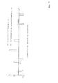
- Fig. 1 to 3 For example, various energy losses are shown within a resource to be diagnosed by the method, which has changed dielectric properties in a range.
- the medium to be examined In order to determine the dielectric properties as a function of the location, the medium to be examined must be scanned across its entire length l with the aid of the method according to the invention. This is done by changing the pulse interval .DELTA.t of the two pulses fed or the pulse pair.
- the total transit time tTransit or tPurchlauf of the pulses must be determined by the resource, which is dependent on the propagation speed and length of the resource, respectively. This can be done for example by means of a reflection measurement in the time domain or in the frequency domain, ie by means of a conventional TDR measurement or FDR measurement. Regardless of the measuring method used to determine all relevant electrical line parameters the smallest pulse interval ⁇ tMin is always dependent on the pulse width tW and must always be greater than or equal to the pulse width tW. The number of time-resolvable steps between ⁇ tMin and ⁇ tMax gives the minimum step size (resolution) of the scan in the axial direction of the resource. The pulse width tW further influences the real width of the interference zone of the two pulses, the propagation speed and the overlap time of the pulses.
- the generation of respectively constructive and destructive interference at a specific point to be examined x of the device to be diagnosed can considerably increase the accuracy of the evaluation of the local parameters or the criteria by suitable algorithms, two options being available:
- Constructive interference can be z. B. by pulse pairs each having the same polarity of the voltage, the same pulse width tW and a defined distance .DELTA.t generate, causing a voltage increase occurs at a point to be examined of the equipment and thus set locally increased dielectric losses.
- Destructive interference can be contrast z. B. by pulse pairs each having the same pulse width tW and defined pulse spacing .DELTA.t, but each generate different polarity of the voltage, whereby a voltage reduction and concomitantly reduced dielectric losses occur at a point to be examined of the equipment.
- detection and localization of strong impedance changes and reflections in the resource can be made using matched TDR or FDR (eg Gaussian Pulse Reversal, Cross Correlation, Resonance Points, Frequency Spectrum).
- TDR eg Gaussian Pulse Reversal, Cross Correlation, Resonance Points, Frequency Spectrum.
- a failure of pulses can be used as an additional comparison criterion, wherein the pulse interval is chosen so large that no interference occurs in the resource (see. Fig. 3 ).
- a counter-simulation with a mint, comparable (reference) resource can be used as a comparison criterion.
- the simulation basis forms an equivalent circuit diagram for frequency-dependent, spatially extended electrical equipment, discretized in n (single) elements.
- the voltage distribution at the input is split (cf. Fig. 9 ) in two components: one is the voltage curve without its reflections and the other is only the voltage curve with the reflections within the equipment. This results in a voltage curve Ue (t) and a voltage curve Ur (t).
- the loss energy in the case of missing interference in the resource is calculated once and for each interference point (constructive or destructive interference).
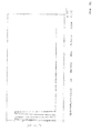
- Fig. 8 shows a diagram in which the dielectric energy losses over the portion of a subject to be examined, in particular a cable for energy transfer, are removed in%.
- the resource has a defective region with significantly degraded dielectric properties.
- the dielectric energy loss (referred size) is used both constructively and in the case of destructive interference of the pulses.
- Fig. 9 shows a schematic representation of an apparatus for performing the spatially resolved diagnostic method according to the invention on an extended resource, in particular a cable for electrical transmission of high electrical energy.
- the device 10 comprises inter alia a pulse or a signal generator 12, a filter system 14 for limiting the band of the input signal as well as a variable impedance 16 for adaptation to different types of operating means 26 or cables are connected downstream.
- a pulse or the signal generator 12 two similar, for example, rectangular pulses 18, 20 are generated with a variable pulse interval .DELTA.t and fed via the filter system 14 and the impedance 16 via a coupling line 22 in a beginning 24 of a device to be diagnosed 26 by way of example .
- the pulses 18, 20 can have an arbitrary voltage or current profile over the time t.
- two pulses 18, 20 are also referred to as a pulse pair in the context of this description.
- the spatially extended operating means 26, which is preferably a multicore high-voltage cable with 3 phases, but at least one core for electrical energy transmission or the like, here comprises by way of example a plurality of 1... N areas or cable segments or cable sections and has one Total length l on.
- an impedance Z is provided, which may be designed as an open end, as a short circuit or as an active termination.
- a preferably virtual, digitally simulated or a real replica 30 of the operating means 26, as indicated by a dotted line may be connected to the coupling line 22.
- a junction 32 in which it is z. B.
- a coupling element and / or a coupler is connected via a (measuring) line 34, a measuring device 36, in particular an analog-to-digital converter with a high sampling rate, with a fast, preferably a digital processing unit 38, such as z.
- a PC a digital oscilloscope, an analyzer, a logic array.
- the digital values of the analog voltages on the measuring line 34 output by the analog-digital converter arrive via data lines 39 (bus) to the arithmetic unit 38 for evaluation.
- the measuring device 36 forms here together with the arithmetic unit 38 an evaluation unit 40.
- the evaluation unit 40 may further not shown input and output devices, such. As screens, projectors, keyboards, sounders, printers, etc. include.
- the triggering or the triggering of the pulse generator preferably takes place on the basis of the results of the signal processing within the arithmetic unit 38.
- the pulse width tW or the temporal length of the pulses 18, 20 is likewise variable, wherein this is preferably the same in each case.
- the evaluation unit 40 By means of the evaluation unit 40, the voltage profile at the beginning 24 of the device 26 designed in the manner of a cable can be measured and evaluated.
- the pulse interval ⁇ t is preferably varied as a function of the results of the evaluation, so that all segments 1... N of the equipment 26 can be subjected to a high-precision, spatially resolved dielectric diagnosis. As a result, if necessary. Defective areas 1 ... N are reliably detected and, under certain circumstances, their remaining service life can be predicted so that an immediate replacement of the affected cable segment can be planned.
- the pulses may also be fed to the start 24 and / or end 28 of the resource 26.
- the pulses 18, 20 one of the in Fig. 9 merely exemplarily shown rectangular shape have a different course and z. B. have a triangular, a sawtooth, a trapezoidal, a sinusoidal, an exponential, a bell-shaped (ie Gaussian) course or a combination of at least two of said geometries.
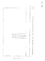
- the Fig. 10 shows the within the (measuring) device of the invention Fig. 9 occurring voltage waveform UA (t) at the beginning 24 of the device 26, which is a superposition of Fig. 11 with the voltage curve UA (t) at the beginning 24 of the device 26 without reflections and of Fig. 12 with the exclusively the reflections containing voltage waveform UA (t) at the beginning 24 of the operating means 26 represents.
- the invention opens up the possibility for the first time of evaluating the state of individual segments or sections of a device to be examined, in particular of a high-voltage cable for electrical energy transmission, and of selectively exchanging them in the event of a fault or predicting their failure.
- z For energy utilities, for example, completely new possibilities in preventive cable diagnostics and asset management.
- Appropriate condition-based and risk-based strategies result in considerable potential savings in the maintenance and servicing of cable routes.
- With the help of the method according to the invention can also heterogeneous cable routes, such.
- the electrical state diagnosis is possible as a function of the location x along the longitudinal extent of the equipment (see g., Spatial resolution). As a result, individual cable segments or cable sections can be evaluated to the nearest meter in terms of their dielectric properties.
- the device also allows, inter alia, a measurement at the end of the equipment, so that no synchronization between the beginning and the end of the equipment is necessary. Rather, only a synchronization between the pulse or the signal generator and the measurement signal acquisition is needed.
- the hardware for signal generation, measurement and control has a compact design and, in contrast to conventional measuring methods and measurement setups, enables problem-free field use in the field, which is a clear advantage represents the state of the art.
Applications Claiming Priority (1)
| Application Number | Priority Date | Filing Date | Title |
|---|---|---|---|
| DE102014005698.8A DE102014005698A1 (de) | 2014-04-11 | 2014-04-11 | Verfahren sowie Vorrichtung zur ortsaufgelösten Diagnose |
Publications (2)
| Publication Number | Publication Date |
|---|---|
| EP2930522A1 true EP2930522A1 (fr) | 2015-10-14 |
| EP2930522B1 EP2930522B1 (fr) | 2019-07-24 |
Family
ID=52824125
Family Applications (1)
| Application Number | Title | Priority Date | Filing Date |
|---|---|---|---|
| EP15163140.5A Active EP2930522B1 (fr) | 2014-04-11 | 2015-04-10 | Procédé et dispositif de diagnostic à résolution spatiale |
Country Status (4)
| Country | Link |
|---|---|
| US (1) | US9880212B2 (fr) |
| EP (1) | EP2930522B1 (fr) |
| CN (1) | CN105021951A (fr) |
| DE (1) | DE102014005698A1 (fr) |
Cited By (1)
| Publication number | Priority date | Publication date | Assignee | Title |
|---|---|---|---|---|
| WO2017216061A1 (fr) * | 2016-06-15 | 2017-12-21 | Leoni Kabel Gmbh | Procédé de surveillance d'une ligne et ensemble de mesure comprenant une ligne |
Families Citing this family (6)
| Publication number | Priority date | Publication date | Assignee | Title |
|---|---|---|---|---|
| DE102013224573B3 (de) * | 2013-11-29 | 2014-10-02 | Hagenuk KMT Kabelmeßtechnik GmbH | Verfahren und Einrichtung zur Ortung von Teilentladungen in elektrischen Kabeln |
| US10382312B2 (en) * | 2016-03-02 | 2019-08-13 | Fisher-Rosemount Systems, Inc. | Detecting and locating process control communication line faults from a handheld maintenance tool |
| JP6716791B2 (ja) * | 2016-11-11 | 2020-07-01 | レオニ カーベル ゲーエムベーハー | 導線を監視するための方法と測定装置 |
| US10663532B2 (en) * | 2017-10-24 | 2020-05-26 | Hamilton Sundstrand Corporation | Method of testing cable shield performance |
| CN109406903A (zh) * | 2018-11-30 | 2019-03-01 | 国网江苏省电力有限公司无锡供电分公司 | 一种电缆接头进水缺陷检测与诊断方法 |
| CN114207458A (zh) * | 2019-08-09 | 2022-03-18 | 瑞典爱立信有限公司 | 向无线电站点中的无线电单元供电的电力线缆的远程诊断 |
Citations (8)
| Publication number | Priority date | Publication date | Assignee | Title |
|---|---|---|---|---|
| US4538103A (en) * | 1982-08-30 | 1985-08-27 | John Cappon | Time domain reflectometer apparatus for identifying the location of cable defects |
| US5270661A (en) * | 1991-10-25 | 1993-12-14 | Pipeline Profiles, Ltd. | Method of detecting a conductor anomaly by applying pulses along the conductor in opposite directions |
| JP2001153913A (ja) | 1999-11-26 | 2001-06-08 | Fujikura Ltd | Cvケーブルの絶縁劣化診断方法 |
| US20060097730A1 (en) | 2002-07-09 | 2006-05-11 | Jin-Bae Park | Time-frequency domain reflectometry apparatus and method |
| US20080048668A1 (en) | 2006-08-25 | 2008-02-28 | Instrument Manufacturing Company (Imcorp) | Diagnostic methods for electrical cables utilizing axial tomography |
| US7966137B2 (en) | 2005-10-03 | 2011-06-21 | Wirescan As | Line resonance analysis system |
| DE102010013103A1 (de) | 2010-03-29 | 2011-09-29 | B2 Electronic Gmbh | Vorrichtung und Verfahren zur Diagnose von Messobjekten unter Verwendung einer Messspannung |
| EP2623999A2 (fr) * | 2012-02-06 | 2013-08-07 | Hagenuk KMT Kabelmesstechnik GmbH | Procédé de localisation d'une faute dans un câble de test et dispositif correspondant |
Family Cites Families (13)
| Publication number | Priority date | Publication date | Assignee | Title |
|---|---|---|---|---|
| US4970467A (en) | 1989-04-27 | 1990-11-13 | Burnett Gale D | Apparatus and method for pulse propagation analysis of a pipeline or the like |
| GB2242324B (en) * | 1990-03-22 | 1993-09-22 | Stc Plc | Fault location. |
| US5361776A (en) * | 1993-08-06 | 1994-11-08 | Telectronics Pacing Systems, Inc. | Time domain reflectometer impedance sensor method of use and implantable cardiac stimulator using same |
| DE19546455C1 (de) * | 1995-12-13 | 1997-05-07 | Wandel & Goltermann | Meßverfahren und Meßanordnung zur Ermittlung der Länge einer elektrischen Leitung mit mehrfachen Reflexionen |
| US6777953B2 (en) * | 2001-01-24 | 2004-08-17 | General Dynamics (Otc) Aerospace, Inc. | Parallel arc fault diagnostic for aircraft wiring |
| US6570388B2 (en) * | 2001-04-06 | 2003-05-27 | United Microeletronics Corp. | Transmission line pulse method for measuring electrostatic discharge voltages |
| US6980007B1 (en) * | 2002-06-07 | 2005-12-27 | Marvell International Ltd. | Cable tester with insertion loss and return loss estimators |
| US7019533B1 (en) * | 2002-06-07 | 2006-03-28 | Marvell International Ltd. | Cable tester |
| US7164274B2 (en) * | 2003-06-11 | 2007-01-16 | Broadcom Corporation | Cable diagnostics using time domain reflectometry and applications using the same |
| US7030621B2 (en) * | 2004-05-04 | 2006-04-18 | General Electric Company | Low current AC partial discharge diagnostic system for wiring diagnostics |
| US7808247B1 (en) * | 2007-02-22 | 2010-10-05 | Marvel International Ltd. | Fast cable tester |
| US8461848B2 (en) * | 2008-12-10 | 2013-06-11 | Marvell International Ltd. | Cable diagnostics for Base-T systems |
| EP2659278B1 (fr) * | 2010-12-30 | 2018-11-21 | Prysmian S.p.A. | Localisation de pannes générant des décharges partielles |
-
2014
- 2014-04-11 DE DE102014005698.8A patent/DE102014005698A1/de not_active Withdrawn
-
2015
- 2015-04-10 EP EP15163140.5A patent/EP2930522B1/fr active Active
- 2015-04-10 US US14/683,390 patent/US9880212B2/en active Active
- 2015-04-13 CN CN201510255468.XA patent/CN105021951A/zh active Pending
Patent Citations (8)
| Publication number | Priority date | Publication date | Assignee | Title |
|---|---|---|---|---|
| US4538103A (en) * | 1982-08-30 | 1985-08-27 | John Cappon | Time domain reflectometer apparatus for identifying the location of cable defects |
| US5270661A (en) * | 1991-10-25 | 1993-12-14 | Pipeline Profiles, Ltd. | Method of detecting a conductor anomaly by applying pulses along the conductor in opposite directions |
| JP2001153913A (ja) | 1999-11-26 | 2001-06-08 | Fujikura Ltd | Cvケーブルの絶縁劣化診断方法 |
| US20060097730A1 (en) | 2002-07-09 | 2006-05-11 | Jin-Bae Park | Time-frequency domain reflectometry apparatus and method |
| US7966137B2 (en) | 2005-10-03 | 2011-06-21 | Wirescan As | Line resonance analysis system |
| US20080048668A1 (en) | 2006-08-25 | 2008-02-28 | Instrument Manufacturing Company (Imcorp) | Diagnostic methods for electrical cables utilizing axial tomography |
| DE102010013103A1 (de) | 2010-03-29 | 2011-09-29 | B2 Electronic Gmbh | Vorrichtung und Verfahren zur Diagnose von Messobjekten unter Verwendung einer Messspannung |
| EP2623999A2 (fr) * | 2012-02-06 | 2013-08-07 | Hagenuk KMT Kabelmesstechnik GmbH | Procédé de localisation d'une faute dans un câble de test et dispositif correspondant |
Non-Patent Citations (1)
| Title |
|---|
| KE LIU ET AL: "Network Cable Fault Location Based on the Wide Pulse Time Domain Reflection", TESTING AND DIAGNOSIS, 2009. ICTD 2009. IEEE CIRCUITS AND SYSTEMS INTERNATIONAL CONFERENCE ON, IEEE, PISCATAWAY, NJ, USA, 28 April 2009 (2009-04-28), pages 1 - 3, XP031460482, ISBN: 978-1-4244-2587-7 * |
Cited By (2)
| Publication number | Priority date | Publication date | Assignee | Title |
|---|---|---|---|---|
| WO2017216061A1 (fr) * | 2016-06-15 | 2017-12-21 | Leoni Kabel Gmbh | Procédé de surveillance d'une ligne et ensemble de mesure comprenant une ligne |
| US11002781B2 (en) | 2016-06-15 | 2021-05-11 | Leoni Kabel Gmbh | Method for monitoring a line, and measuring arrangement containing line |
Also Published As
| Publication number | Publication date |
|---|---|
| CN105021951A (zh) | 2015-11-04 |
| EP2930522B1 (fr) | 2019-07-24 |
| DE102014005698A1 (de) | 2015-10-15 |
| US9880212B2 (en) | 2018-01-30 |
| US20150316599A1 (en) | 2015-11-05 |
Similar Documents
| Publication | Publication Date | Title |
|---|---|---|
| EP2930522B1 (fr) | Procédé et dispositif de diagnostic à résolution spatiale | |
| EP2482089B1 (fr) | Procédé et système de localisation d'une erreur sur un câble | |
| DE69333936T2 (de) | Lokalisierung von fehlern in kabeln | |
| DE102006043120B4 (de) | Breitband-Ultrahochfrequenz-Simulations-Teilentladungsgenerator | |
| DE2656911C2 (fr) | ||
| EP3223026A1 (fr) | Procede, dispositif et systeme destines a localiser un defaut sur une ligne d'un reseau d'alimentation electrique | |
| DE2404223A1 (de) | Verfahren zur messung von teilentladungen und zur ortung von fehlstellen in der isolierung von isolierten leitern | |
| DE60020050T2 (de) | Verfahren und Vorrichtung zur Ortung der Quelle von Teilentladungen | |
| DE112008001713B4 (de) | System und Verfahren zum Ermitteln der Position einer Teilentladung in einer elektrischen Einrichtung | |
| EP3781812A1 (fr) | Contrôle de parafoudres d'éoliennes | |
| EP3968038A1 (fr) | Procédé et dispositif de détermination d'un emplacement défectueux dans un réseau d'alimentation en énergie électrique | |
| EP2392934A1 (fr) | Procédé et appareil de surveillance d'un parafoudre d'un système de câble | |
| WO2003012466A2 (fr) | Procede de localisation de defauts, notamment sur des reseaux basse et moyenne tension ramifies et circuit d'evaluation utilise a cet effet | |
| EP3719510B1 (fr) | Procédé, dispositif et système de détection d'un emplacement de défaillance sur une conduite d'un réseau d'alimentation électrique | |
| WO2009046751A1 (fr) | Procédé pour déterminer la répartition de température le long d'un conducteur | |
| CH649847A5 (en) | Method for fault location in an electrical line | |
| EP1430318B1 (fr) | Procede et dispositif de localisation d'une erreur dans une ligne | |
| EP2553477B1 (fr) | Dispositif et procédé de diagnostic d'objets de mesure en utilisant une tension de mesure | |
| DE102019104742A1 (de) | Vorrichtung und Verfahren zum automatischen Erfassen einer Teilentladung | |
| EP3014291B1 (fr) | Contrôle de la terminaison de conducteurs partiels de barres de stator de machines électriques | |
| EP3269015B1 (fr) | Procédé de détermination d'état et de localisation de défauts sur des dérivations isolées installées dans un système de protection extérieure contre la foudre | |
| WO2019179645A1 (fr) | Procédé et ensemble de mesure destiné à la détection d'une perturbation électromagnétique sur l'âme dun conducteur électrique | |
| EP3914918B1 (fr) | Test de limiteurs de tension de gaine | |
| EP3769097B1 (fr) | Ensemble de mesure et procédé pour surveiller un câble | |
| DE2644157A1 (de) | Geraet zur lokalisierung von fehlerstellen in elektrischen kabeln |
Legal Events
| Date | Code | Title | Description |
|---|---|---|---|
| PUAI | Public reference made under article 153(3) epc to a published international application that has entered the european phase |
Free format text: ORIGINAL CODE: 0009012 |
|
| AK | Designated contracting states |
Kind code of ref document: A1 Designated state(s): AL AT BE BG CH CY CZ DE DK EE ES FI FR GB GR HR HU IE IS IT LI LT LU LV MC MK MT NL NO PL PT RO RS SE SI SK SM TR |
|
| AX | Request for extension of the european patent |
Extension state: BA ME |
|
| 17P | Request for examination filed |
Effective date: 20160412 |
|
| RBV | Designated contracting states (corrected) |
Designated state(s): AL AT BE BG CH CY CZ DE DK EE ES FI FR GB GR HR HU IE IS IT LI LT LU LV MC MK MT NL NO PL PT RO RS SE SI SK SM TR |
|
| REG | Reference to a national code |
Ref country code: DE Ref legal event code: R079 Ref document number: 502015009715 Country of ref document: DE Free format text: PREVIOUS MAIN CLASS: G01R0031080000 Ipc: G01R0031020000 |
|
| GRAP | Despatch of communication of intention to grant a patent |
Free format text: ORIGINAL CODE: EPIDOSNIGR1 |
|
| STAA | Information on the status of an ep patent application or granted ep patent |
Free format text: STATUS: GRANT OF PATENT IS INTENDED |
|
| RIC1 | Information provided on ipc code assigned before grant |
Ipc: G01R 31/11 20060101ALI20190211BHEP Ipc: G01R 31/08 20060101ALI20190211BHEP Ipc: G01R 31/02 20060101AFI20190211BHEP |
|
| INTG | Intention to grant announced |
Effective date: 20190306 |
|
| GRAS | Grant fee paid |
Free format text: ORIGINAL CODE: EPIDOSNIGR3 |
|
| GRAA | (expected) grant |
Free format text: ORIGINAL CODE: 0009210 |
|
| STAA | Information on the status of an ep patent application or granted ep patent |
Free format text: STATUS: THE PATENT HAS BEEN GRANTED |
|
| REG | Reference to a national code |
Ref country code: DE Ref legal event code: R081 Ref document number: 502015009715 Country of ref document: DE Owner name: SEBA-DYNATRONIC MESS- UND ORTUNGSTECHNIK GMBH, DE Free format text: FORMER OWNER: SEBA-DYNATRONIC MESS- UND ORTUNGSTECHNIK GMBH, 96148 BAUNACH, DE Ref country code: DE Ref legal event code: R081 Ref document number: 502015009715 Country of ref document: DE Owner name: FRIEDRICH-ALEXANDER-UNIVERSITAET ERLANGEN-NUER, DE Free format text: FORMER OWNER: SEBA-DYNATRONIC MESS- UND ORTUNGSTECHNIK GMBH, 96148 BAUNACH, DE |
|
| AK | Designated contracting states |
Kind code of ref document: B1 Designated state(s): AL AT BE BG CH CY CZ DE DK EE ES FI FR GB GR HR HU IE IS IT LI LT LU LV MC MK MT NL NO PL PT RO RS SE SI SK SM TR |
|
| REG | Reference to a national code |
Ref country code: GB Ref legal event code: FG4D Free format text: NOT ENGLISH |
|
| REG | Reference to a national code |
Ref country code: CH Ref legal event code: EP |
|
| REG | Reference to a national code |
Ref country code: DE Ref legal event code: R096 Ref document number: 502015009715 Country of ref document: DE |
|
| REG | Reference to a national code |
Ref country code: AT Ref legal event code: REF Ref document number: 1158808 Country of ref document: AT Kind code of ref document: T Effective date: 20190815 |
|
| REG | Reference to a national code |
Ref country code: IE Ref legal event code: FG4D Free format text: LANGUAGE OF EP DOCUMENT: GERMAN |
|
| REG | Reference to a national code |
Ref country code: DE Ref legal event code: R079 Ref document number: 502015009715 Country of ref document: DE Free format text: PREVIOUS MAIN CLASS: G01R0031020000 Ipc: G01R0031500000 |
|
| REG | Reference to a national code |
Ref country code: NL Ref legal event code: MP Effective date: 20190724 |
|
| REG | Reference to a national code |
Ref country code: NO Ref legal event code: T2 Effective date: 20190724 |
|
| REG | Reference to a national code |
Ref country code: LT Ref legal event code: MG4D |
|
| PG25 | Lapsed in a contracting state [announced via postgrant information from national office to epo] |
Ref country code: SE Free format text: LAPSE BECAUSE OF FAILURE TO SUBMIT A TRANSLATION OF THE DESCRIPTION OR TO PAY THE FEE WITHIN THE PRESCRIBED TIME-LIMIT Effective date: 20190724 Ref country code: HR Free format text: LAPSE BECAUSE OF FAILURE TO SUBMIT A TRANSLATION OF THE DESCRIPTION OR TO PAY THE FEE WITHIN THE PRESCRIBED TIME-LIMIT Effective date: 20190724 Ref country code: LT Free format text: LAPSE BECAUSE OF FAILURE TO SUBMIT A TRANSLATION OF THE DESCRIPTION OR TO PAY THE FEE WITHIN THE PRESCRIBED TIME-LIMIT Effective date: 20190724 Ref country code: PT Free format text: LAPSE BECAUSE OF FAILURE TO SUBMIT A TRANSLATION OF THE DESCRIPTION OR TO PAY THE FEE WITHIN THE PRESCRIBED TIME-LIMIT Effective date: 20191125 Ref country code: FI Free format text: LAPSE BECAUSE OF FAILURE TO SUBMIT A TRANSLATION OF THE DESCRIPTION OR TO PAY THE FEE WITHIN THE PRESCRIBED TIME-LIMIT Effective date: 20190724 Ref country code: NL Free format text: LAPSE BECAUSE OF FAILURE TO SUBMIT A TRANSLATION OF THE DESCRIPTION OR TO PAY THE FEE WITHIN THE PRESCRIBED TIME-LIMIT Effective date: 20190724 Ref country code: BG Free format text: LAPSE BECAUSE OF FAILURE TO SUBMIT A TRANSLATION OF THE DESCRIPTION OR TO PAY THE FEE WITHIN THE PRESCRIBED TIME-LIMIT Effective date: 20191024 |
|
| PG25 | Lapsed in a contracting state [announced via postgrant information from national office to epo] |
Ref country code: AL Free format text: LAPSE BECAUSE OF FAILURE TO SUBMIT A TRANSLATION OF THE DESCRIPTION OR TO PAY THE FEE WITHIN THE PRESCRIBED TIME-LIMIT Effective date: 20190724 Ref country code: ES Free format text: LAPSE BECAUSE OF FAILURE TO SUBMIT A TRANSLATION OF THE DESCRIPTION OR TO PAY THE FEE WITHIN THE PRESCRIBED TIME-LIMIT Effective date: 20190724 Ref country code: LV Free format text: LAPSE BECAUSE OF FAILURE TO SUBMIT A TRANSLATION OF THE DESCRIPTION OR TO PAY THE FEE WITHIN THE PRESCRIBED TIME-LIMIT Effective date: 20190724 Ref country code: IS Free format text: LAPSE BECAUSE OF FAILURE TO SUBMIT A TRANSLATION OF THE DESCRIPTION OR TO PAY THE FEE WITHIN THE PRESCRIBED TIME-LIMIT Effective date: 20191124 Ref country code: RS Free format text: LAPSE BECAUSE OF FAILURE TO SUBMIT A TRANSLATION OF THE DESCRIPTION OR TO PAY THE FEE WITHIN THE PRESCRIBED TIME-LIMIT Effective date: 20190724 Ref country code: GR Free format text: LAPSE BECAUSE OF FAILURE TO SUBMIT A TRANSLATION OF THE DESCRIPTION OR TO PAY THE FEE WITHIN THE PRESCRIBED TIME-LIMIT Effective date: 20191025 |
|
| PG25 | Lapsed in a contracting state [announced via postgrant information from national office to epo] |
Ref country code: TR Free format text: LAPSE BECAUSE OF FAILURE TO SUBMIT A TRANSLATION OF THE DESCRIPTION OR TO PAY THE FEE WITHIN THE PRESCRIBED TIME-LIMIT Effective date: 20190724 |
|
| PG25 | Lapsed in a contracting state [announced via postgrant information from national office to epo] |
Ref country code: IT Free format text: LAPSE BECAUSE OF FAILURE TO SUBMIT A TRANSLATION OF THE DESCRIPTION OR TO PAY THE FEE WITHIN THE PRESCRIBED TIME-LIMIT Effective date: 20190724 Ref country code: RO Free format text: LAPSE BECAUSE OF FAILURE TO SUBMIT A TRANSLATION OF THE DESCRIPTION OR TO PAY THE FEE WITHIN THE PRESCRIBED TIME-LIMIT Effective date: 20190724 Ref country code: DK Free format text: LAPSE BECAUSE OF FAILURE TO SUBMIT A TRANSLATION OF THE DESCRIPTION OR TO PAY THE FEE WITHIN THE PRESCRIBED TIME-LIMIT Effective date: 20190724 Ref country code: EE Free format text: LAPSE BECAUSE OF FAILURE TO SUBMIT A TRANSLATION OF THE DESCRIPTION OR TO PAY THE FEE WITHIN THE PRESCRIBED TIME-LIMIT Effective date: 20190724 Ref country code: PL Free format text: LAPSE BECAUSE OF FAILURE TO SUBMIT A TRANSLATION OF THE DESCRIPTION OR TO PAY THE FEE WITHIN THE PRESCRIBED TIME-LIMIT Effective date: 20190724 |
|
| PG25 | Lapsed in a contracting state [announced via postgrant information from national office to epo] |
Ref country code: IS Free format text: LAPSE BECAUSE OF FAILURE TO SUBMIT A TRANSLATION OF THE DESCRIPTION OR TO PAY THE FEE WITHIN THE PRESCRIBED TIME-LIMIT Effective date: 20200224 Ref country code: SM Free format text: LAPSE BECAUSE OF FAILURE TO SUBMIT A TRANSLATION OF THE DESCRIPTION OR TO PAY THE FEE WITHIN THE PRESCRIBED TIME-LIMIT Effective date: 20190724 Ref country code: SK Free format text: LAPSE BECAUSE OF FAILURE TO SUBMIT A TRANSLATION OF THE DESCRIPTION OR TO PAY THE FEE WITHIN THE PRESCRIBED TIME-LIMIT Effective date: 20190724 Ref country code: CZ Free format text: LAPSE BECAUSE OF FAILURE TO SUBMIT A TRANSLATION OF THE DESCRIPTION OR TO PAY THE FEE WITHIN THE PRESCRIBED TIME-LIMIT Effective date: 20190724 |
|
| REG | Reference to a national code |
Ref country code: DE Ref legal event code: R097 Ref document number: 502015009715 Country of ref document: DE |
|
| PLBE | No opposition filed within time limit |
Free format text: ORIGINAL CODE: 0009261 |
|
| STAA | Information on the status of an ep patent application or granted ep patent |
Free format text: STATUS: NO OPPOSITION FILED WITHIN TIME LIMIT |
|
| PG2D | Information on lapse in contracting state deleted |
Ref country code: IS |
|
| 26N | No opposition filed |
Effective date: 20200603 |
|
| PG25 | Lapsed in a contracting state [announced via postgrant information from national office to epo] |
Ref country code: SI Free format text: LAPSE BECAUSE OF FAILURE TO SUBMIT A TRANSLATION OF THE DESCRIPTION OR TO PAY THE FEE WITHIN THE PRESCRIBED TIME-LIMIT Effective date: 20190724 |
|
| PG25 | Lapsed in a contracting state [announced via postgrant information from national office to epo] |
Ref country code: MC Free format text: LAPSE BECAUSE OF FAILURE TO SUBMIT A TRANSLATION OF THE DESCRIPTION OR TO PAY THE FEE WITHIN THE PRESCRIBED TIME-LIMIT Effective date: 20190724 |
|
| REG | Reference to a national code |
Ref country code: CH Ref legal event code: PL |
|
| PG25 | Lapsed in a contracting state [announced via postgrant information from national office to epo] |
Ref country code: FR Free format text: LAPSE BECAUSE OF NON-PAYMENT OF DUE FEES Effective date: 20200430 Ref country code: LU Free format text: LAPSE BECAUSE OF NON-PAYMENT OF DUE FEES Effective date: 20200410 Ref country code: CH Free format text: LAPSE BECAUSE OF NON-PAYMENT OF DUE FEES Effective date: 20200430 Ref country code: LI Free format text: LAPSE BECAUSE OF NON-PAYMENT OF DUE FEES Effective date: 20200430 |
|
| REG | Reference to a national code |
Ref country code: BE Ref legal event code: MM Effective date: 20200430 |
|
| PG25 | Lapsed in a contracting state [announced via postgrant information from national office to epo] |
Ref country code: BE Free format text: LAPSE BECAUSE OF NON-PAYMENT OF DUE FEES Effective date: 20200430 |
|
| GBPC | Gb: european patent ceased through non-payment of renewal fee |
Effective date: 20200410 |
|
| PG25 | Lapsed in a contracting state [announced via postgrant information from national office to epo] |
Ref country code: IE Free format text: LAPSE BECAUSE OF NON-PAYMENT OF DUE FEES Effective date: 20200410 Ref country code: GB Free format text: LAPSE BECAUSE OF NON-PAYMENT OF DUE FEES Effective date: 20200410 |
|
| PG25 | Lapsed in a contracting state [announced via postgrant information from national office to epo] |
Ref country code: MT Free format text: LAPSE BECAUSE OF FAILURE TO SUBMIT A TRANSLATION OF THE DESCRIPTION OR TO PAY THE FEE WITHIN THE PRESCRIBED TIME-LIMIT Effective date: 20190724 Ref country code: CY Free format text: LAPSE BECAUSE OF FAILURE TO SUBMIT A TRANSLATION OF THE DESCRIPTION OR TO PAY THE FEE WITHIN THE PRESCRIBED TIME-LIMIT Effective date: 20190724 |
|
| PG25 | Lapsed in a contracting state [announced via postgrant information from national office to epo] |
Ref country code: MK Free format text: LAPSE BECAUSE OF FAILURE TO SUBMIT A TRANSLATION OF THE DESCRIPTION OR TO PAY THE FEE WITHIN THE PRESCRIBED TIME-LIMIT Effective date: 20190724 |
|
| PGFP | Annual fee paid to national office [announced via postgrant information from national office to epo] |
Ref country code: NO Payment date: 20220421 Year of fee payment: 8 Ref country code: DE Payment date: 20220419 Year of fee payment: 8 |
|
| PGFP | Annual fee paid to national office [announced via postgrant information from national office to epo] |
Ref country code: AT Payment date: 20220414 Year of fee payment: 8 |
|
| REG | Reference to a national code |
Ref country code: DE Ref legal event code: R119 Ref document number: 502015009715 Country of ref document: DE |
|
| REG | Reference to a national code |
Ref country code: NO Ref legal event code: MMEP |
|
| REG | Reference to a national code |
Ref country code: AT Ref legal event code: MM01 Ref document number: 1158808 Country of ref document: AT Kind code of ref document: T Effective date: 20230410 |
|
| PG25 | Lapsed in a contracting state [announced via postgrant information from national office to epo] |
Ref country code: NO Free format text: LAPSE BECAUSE OF NON-PAYMENT OF DUE FEES Effective date: 20230430 Ref country code: DE Free format text: LAPSE BECAUSE OF NON-PAYMENT OF DUE FEES Effective date: 20231103 Ref country code: AT Free format text: LAPSE BECAUSE OF NON-PAYMENT OF DUE FEES Effective date: 20230410 |