EP2930118A1 - Container handling device and method for holding, gripping and/or turning containers - Google Patents
Container handling device and method for holding, gripping and/or turning containers Download PDFInfo
- Publication number
- EP2930118A1 EP2930118A1 EP15159947.9A EP15159947A EP2930118A1 EP 2930118 A1 EP2930118 A1 EP 2930118A1 EP 15159947 A EP15159947 A EP 15159947A EP 2930118 A1 EP2930118 A1 EP 2930118A1
- Authority
- EP
- European Patent Office
- Prior art keywords
- holding
- container
- centering
- container handling
- handling device
- Prior art date
- Legal status (The legal status is an assumption and is not a legal conclusion. Google has not performed a legal analysis and makes no representation as to the accuracy of the status listed.)
- Granted
Links
- 238000000034 method Methods 0.000 title claims abstract description 17
- 230000000284 resting effect Effects 0.000 claims abstract 2
- 239000000725 suspension Substances 0.000 claims description 2
- 238000004873 anchoring Methods 0.000 claims 1
- 238000002372 labelling Methods 0.000 description 4
- 229920003023 plastic Polymers 0.000 description 4
- 230000008901 benefit Effects 0.000 description 3
- 239000011521 glass Substances 0.000 description 3
- 230000008569 process Effects 0.000 description 3
- 239000003999 initiator Substances 0.000 description 2
- 238000007689 inspection Methods 0.000 description 2
- 238000007639 printing Methods 0.000 description 2
- 230000004913 activation Effects 0.000 description 1
- 238000006243 chemical reaction Methods 0.000 description 1
- 230000006835 compression Effects 0.000 description 1
- 238000007906 compression Methods 0.000 description 1
- 230000001419 dependent effect Effects 0.000 description 1
- 238000011161 development Methods 0.000 description 1
- 230000018109 developmental process Effects 0.000 description 1
- 230000000694 effects Effects 0.000 description 1
- 229920002457 flexible plastic Polymers 0.000 description 1
- 230000007246 mechanism Effects 0.000 description 1
- 238000012986 modification Methods 0.000 description 1
- 230000004048 modification Effects 0.000 description 1
- 230000009467 reduction Effects 0.000 description 1
Images

Classifications
-
- B—PERFORMING OPERATIONS; TRANSPORTING
- B65—CONVEYING; PACKING; STORING; HANDLING THIN OR FILAMENTARY MATERIAL
- B65C—LABELLING OR TAGGING MACHINES, APPARATUS, OR PROCESSES
- B65C3/00—Labelling other than flat surfaces
- B65C3/06—Affixing labels to short rigid containers
- B65C3/08—Affixing labels to short rigid containers to container bodies
- B65C3/14—Affixing labels to short rigid containers to container bodies the container being positioned for labelling with its centre-line vertical
-
- B—PERFORMING OPERATIONS; TRANSPORTING
- B41—PRINTING; LINING MACHINES; TYPEWRITERS; STAMPS
- B41J—TYPEWRITERS; SELECTIVE PRINTING MECHANISMS, i.e. MECHANISMS PRINTING OTHERWISE THAN FROM A FORME; CORRECTION OF TYPOGRAPHICAL ERRORS
- B41J3/00—Typewriters or selective printing or marking mechanisms characterised by the purpose for which they are constructed
- B41J3/407—Typewriters or selective printing or marking mechanisms characterised by the purpose for which they are constructed for marking on special material
- B41J3/4073—Printing on three-dimensional objects not being in sheet or web form, e.g. spherical or cubic objects
- B41J3/40733—Printing on cylindrical or rotationally symmetrical objects, e. g. on bottles
-
- B—PERFORMING OPERATIONS; TRANSPORTING
- B65—CONVEYING; PACKING; STORING; HANDLING THIN OR FILAMENTARY MATERIAL
- B65C—LABELLING OR TAGGING MACHINES, APPARATUS, OR PROCESSES
- B65C3/00—Labelling other than flat surfaces
- B65C3/26—Affixing labels to non-rigid containers, e.g. bottles made of polyethylene, boxes to be inflated by internal air pressure prior to labelling
-
- B—PERFORMING OPERATIONS; TRANSPORTING
- B65—CONVEYING; PACKING; STORING; HANDLING THIN OR FILAMENTARY MATERIAL
- B65C—LABELLING OR TAGGING MACHINES, APPARATUS, OR PROCESSES
- B65C9/00—Details of labelling machines or apparatus
- B65C9/02—Devices for moving articles, e.g. containers, past labelling station
- B65C9/04—Devices for moving articles, e.g. containers, past labelling station having means for rotating the articles
- B65C9/045—Devices for moving articles, e.g. containers, past labelling station having means for rotating the articles adapted for accommodating articles of different diameters, e.g. for adapting the program of rotation to the diameter of the articles
Definitions
- the present invention relates to a container handling device for holding, gripping and / or rotating containers on a support at its upper mouth and / or at its neck region with the features of independent claim 1.
- the invention also relates to a method for holding, gripping and / or or rotating containers standing on a support of such a container handling device with the features of independent method claim 14.
- a so-called. Centering head which engages on the upper side of a vessel or a container, which stands on a support such as a turntable.
- the centering head is normally part of a more complex container treatment machine and serves for axially clamping one of a plurality of containers located in the machine and each on a separate turntable.
- the centering head according to the invention has a replaceable turret with different centering bells and / or inserts.
- Such holding devices are, for example, from the DE 40 35 998 or DE 10 2009 025 907 known.
- multi-part centering devices have already been developed for special tasks, as for example.
- DE 41 14 025 and DE 20 006 237 are disclosed.
- a first object of the present invention is to provide a universally usable centering head which has high flexibility in operation through suitability for different container shapes and / or sizes, and allows setup times to be changed to other container shapes and / or sizes. or to reduce container sizes.
- the invention proposes a device for handling and / or treating containers with the features of independent claim 1.
- the device is prepared and equipped for holding, gripping and / or rotating containers standing on a support at its upper mouth and / or at its neck region and comprises at least two holding and / or centering elements which can be vertically adjusted and / or transmit a vertical holding force, which are alternately adjustable between an operating position and a rest position, so that each holding in the operating position holding and / or centering element can be brought into engagement with a container.
- the at least two holding and / or centering elements are arranged on a common holding device, by its rotation about a defined pivot angle each holding and / or centering element is pivotable between its operating and rest position.
- the holding device can be lowered for fixing a standing on the support or a turntable container variable in the vertical direction, preferably in different height levels, so that different sized containers alike can be kept.
- the edition is usually turntable, which serve the rotatable receiving a respective container.
- turntables with associated holding and / or fixing devices or centering elements may be arranged on the outer circumference of a rotatable machine part, which may be part of a more complex container handling and / or handling machine.
- the holding device can be raised again in the vertical direction, whereby the neck or mouth region of the container is released and the container can be removed from the support.
- the at least two holding and / or centering elements are mounted on the common holding device, so that each holding in the operating position holding and / or centering element are brought from above by vertical lowering with the neck or mouth region of the container standing on the support can, while the respectively pivoted from the engagement area with the container or rotated and thus in rest position holding and / or centering is oriented in the lateral direction where it does not collide with the container nor collide with an adjacent container or holding element of an immediately adjacent container position or come into contact.
- the holding device is rotatably mounted on a machine holder, which in turn is preferably rotatable about a vertical axis of rotation, so that it can interact in particular with rotatably mounted supports or turntables on which the containers are with their underside, so that a corresponding positioning of the container or vessel is made possible by a controlled motor rotation of the machine holder to a predeterminable angle of rotation.
- the holder rotatably mounted on the machine holder may in particular have a pivot or pivot axis which is inclined by approximately 45 degrees relative to the vertical, whereby the respective holding and / or centering devices can be brought into the operating position or in the rest position, without requiring large Pivoting or travel paths are required.
- a kind of revolving magazine is formed, which can provide several differently shaped and dimensioned holding or centering available, of which there is only one in each operating position, in which they have a vertically extending longitudinal extension and effective direction to the respective container which stands on the support or on the turntable, while the other respective holding or Centering devices are brought into a rest position, in which their longitudinal direction, for example, can be horizontal or at a different angle.
- the respective longitudinal axes of the at least two holding and / or centering elements which are fixed to the common holding device, respectively cut the rotary or pivot axis of the rotatable holding device at an angle of about 45 degrees, respectively the above-mentioned revolver-like adjustment mechanism is formed, which allows a very fast conversion, without the need for manual intervention or replacement of parts would be required.
- the holding device is rotatable about its longitudinal axis in several latching steps, a fast manual switch between rest and operating position can be achieved by corresponding pivoting of the holding device to the inclined, in particular inclined by 45 degrees rotational or pivot axis.
- the latching steps can advantageously each have graduations of, for example, about 60 degrees or even about 90 degrees or about 120 degrees. Other graduations are conceivable, possibly also with divergent angular divisions.
- the inventive design of the container handling device also allows further equipment features, so that the holding and / or centering elements, for example, each may be equipped with a central air line or air duct, which can be performed in integrated design in each case by the holding devices to the machine holder.
- air ducts to the holding device, bypassing the central machine holder are conceivable, which can be attached to the holding device suitable line connections for flexible air ducts.
- These air lines can be used particularly advantageously for supplying sterilized air into the container, which is advantageous, for example, in arrangements in a sterile environment or in a clean room.
- the air lines can optionally be used to supply the container sterile air.
- Another advantage of the arrangement is the particularly compact design, which has an advantageous effect in a sterile environment.
- a compact design is particularly advantageous when a container treatment device operates in the so-called. Clean room.
- the at least two holding and / or centering elements arranged on the common holding device can each be adjusted manually between their operating position and their rest position.
- the at least two holding and / or centering elements arranged on the common holding device can be adjusted by motor, in particular by an electric motor, between their operating position and their rest position.
- the machine holder is raised and lowered by a motor and optionally provided with an additional torque support to ensure an exact spatial positioning of the holding and / or centering.
- These can in turn be equipped with various attachments such as, for example, holding bells, suction elements, stamps, etc.
- the present invention can also be characterized in that it proposes a holding device that is extremely variable in adaptable to different container shapes, contours and sizes, which can, for example, have a rotatable turret with preferably up to six receptacles for different centering bells.
- the revolver is rotatably mounted by hand and can be fixed, for example, via a locking element in a desired position.
- the turret can also be rotated via a suitable actuator and, for example, be fixed via a pneumatically operated plunger in the selected rotational position or operating position. It is also conceivable to query the currently selected plunger position via an initiator or other sensor unit in order to ensure the desired position and to facilitate actuation by an actuator, such as an electromotive adjustment drive.
- the turret has a torque support and a sprung pressure piece to obtain a Vorarret ist during the changeover.
- a further object of the present invention is to provide a universally applicable container treatment method which, by being applicable to different container shapes and / or sizes, has a high flexibility in operation and which enables set-up times to be converted to others To reduce container shapes and / or container sizes.
- the invention proposes a method for holding, gripping and / or rotating containers standing on a support of a container handling apparatus at their respective upper mouth and / or at their neck region, which has the following features.
- at least two holding and / or centering elements which are vertically adjustable and / or transmit a vertical holding force are alternately adjusted between an operating position and a rest position or are alternately brought into an operating position or a rest position, so that the respective holding position is in the operating position. and / or centering element is brought into engagement with a container which stands on the support.
- the at least two holding and / or centering elements are arranged on a common holding device, that each holding and / or centering element can be pivoted between its operating and rest position by its rotation about a defined pivoting angle.
- FIG. 1 shows an embodiment of a portion of a device 10 according to the invention for handling and / or treatment of containers 12, the representation thereof in its entirety is omitted here for the sake of clarity.
- the partially identifiable device 10 is prepared and equipped for holding, gripping, and / or rotating cushioned containers 12 at its upper mouth 14 and / or at its neck area, as shown in FIG Fig. 1 is indicated schematically.
- the device 10 shown there by way of example is vertically adjustable as a whole, ie lowered in the direction of arrow 16 to first set up with a vertically downwardly facing centering element 18 on the mouth 14 of the container 12 and this with a defined pressing force on the turntable or the support (not shown ).
- the entire device 10 is vertically raised and lowered not only in the direction of arrow 16, but also rotatable about the vertical longitudinal axis 20, whereby the container 12 together with the turntable on which it stands to rotate and position in the desired manner, which, for example. a labeling, a printing of the container outside, its inspection, etc. easier or can make meaningful.
- the device 10 comprises a total of two such centering elements 18, which are each configured differently and which are each intended to transmit a vertical holding force to the mouth 14 of the container 12 in its vertical downwardly facing operating position.
- the two centering elements 18 are attached to a common holding device 22, by means of which each of the two centering elements 18 can be pivoted between an operating position and a rest position. That in the presentation of the Fig. 1 pointing vertically downwards and just above the mouth 14 of the container 12 located centering element 18 is in the operating position and thus in an active standby position so that it can be placed by vertical adjustment in the direction of arrow 16 down to the container 12 and thus activated.
- the horizontal pointing to the left second centering element 18, the contour of which differs slightly from the other centering element 18, in a non-active rest position since it can not be placed on the container 12 in this horizontal rest position.
- the two centering elements 18 are each formed as Zentrierglocken 24, the wider lower umbrella-like centering engage around the mouth 14 of the container 12 and thus can hold securely when it is placed on it.
- Above the centering 24 is followed by a respective hollow cylindrical shaft portion 26, which are pushed for releasable attachment of the centering 18 on a correspondingly sized mounting pin 28 largely free of play on this and can be clamped and fixed by a clamping lever 30.
- the two cylindrical mounting pins 28, the outer diameter of which corresponds in each case to the inner diameter of the central bores of the two hollow cylindrical shaft sections 26 of the respective centering elements 18, are anchored to the rotatable holding device 22, which is formed in two parts.
- An axle 32 is fixedly connected to the vertical (arrow 16) adjustable and rotatable about the vertical longitudinal axis 20 device holder 34 so that it is both lifted and lowered together with this and rotated about the axis 20.
- axle bearing 32 carries and supports a tilted by about 45 degrees to the vertical longitudinal axis 20 and this intersecting in the 45 ° angle pivot axis 36 with obliquely downwardly facing mushroom-like widening 38 with conical outer surface, which the two Fastening pin 28 carries and centrally to the axis 36 also has an obliquely downward pointing and easily accessible for manual adjustment rotary knob 40.
- the axle receptacle 32 On the back of the mushroom-like widening 38, the axle receptacle 32 carries an axially adjustable locking bolt 42, which engages in the locked state in the rear end face of the mushroom-like widening 38 and thus blocks a rotation of the pivot axis 36 within the axle receptacle 32. If the locking bolt 42, however, unlocked by twisting or manual axial train obliquely upwards, the entire broadening 38 together with the held on the broadening 38 centering elements 18 can be rotated about the pivot axis 36 by manually turning the central rotary knob 40, thereby simultaneously the centering elements 18 between an operating position and a rest position can be pivoted.
- the holding device 22 after manual actuation of the locking bolt 42 and manual rotation of the rotary knob 40, the holding device 22, for example, be rotated by 180 degrees, which causes an exchange of the positions of the two centering elements 18, since these at respectively opposite and thus offset by 180 degrees positions on the conical outer surface of the mushroom-like widening 38 of the holding device 22 are arranged and fixed.
- the Fig. 1 allows a plurality of threaded holes 44 on the conical outer surface of the mushroom-like widening 38 of rotatable about the pivot axis 36 holding device 22, in each of which a separate mounting pin 28 can be screwed, which in turn can each hold a separate centering element 18 in the manner shown.
- a separate mounting pin 28 can be screwed, which in turn can each hold a separate centering element 18 in the manner shown.
- the taper of the threaded holes 44 bearing outer surface of the holding device coincides with the inclination of the pivot axis 36.
- Both the mentioned taper and the inclination of the pivot axis 36 are in the illustrated embodiment 45 degrees, whereby the exact vertical position of the downwardly pointing, rotated in operating position centering element 18 is ensured.
- a plurality of threaded holes 44 are provided at the widening 38 of the holding device 22 a plurality of threaded holes 44 at regular intervals from each other, which are each located at 60-degree intervals. If in each of these threaded holes 44, a mounting pin 28 is arranged to receive a centering element 18, and also if the rear end face of the widening 38 has a corresponding number of regularly spaced mounting holes for locking with the locking pin 42, then by twist angle of 60 degrees around the pivot axis 36 in total to be carried to six different centering elements 18 with the device 10 and brought by appropriate rotation about the axis 36 in the operating position.
- centering elements 18 fastened to the holding device 22, however, it must be ensured that the centering elements 18 of adjacent devices 10, which are in each case in the rest position, do not touch each other. If the distance between a plurality of adjacent devices 10 is insufficient for this purpose, a restriction to only two or three centering elements 18 per holding device 22 may be required.
- the holding device 22 for fixing a standing on the support or the turntable container 12 can be variably lowered in the vertical direction 16, preferably in different height levels, so that different sized container 12 can be equally held.
- the edition is usually turntable, which serve the rotatable receiving a respective container 12.
- Several such turntables with associated holding and / or fixing means or centering elements 18 may be arranged on the outer circumference of a rotatable machine part, which may be part of a more complex container handling and / or container handling machine (not shown).
- the holding device 22 can be raised again along the vertical longitudinal axis 20 in the vertical direction, whereby the neck or mouth region 14 of the container 12 is released and the container 12 can be removed from the support.
- the at least two holding and / or centering elements 18 are mounted and fixed on the common holding device 22, so that each holding in the operating position holding and / or centering element 18 from above by vertical lowering with the neck or mouth region 14 of the support standing container 12 can be brought into engagement while the respectively pivoted from the engagement area with the container 12 or rotated and thus in rest position holding and / or centering element 18 is oriented in the lateral direction, where it neither collide with the container 12 nor with an adjacent container 12 or holding element of an immediately adjacent container position may collide or come into contact.
- the two or more arranged on the common holding device 22 holding and / or centering elements 18 each between their operating position (vertically aligned with the longitudinal axis 20) and its rest position (horizontal position in Fig. 1 ) can be adjusted manually, by actuation of the locking bolt 42 and by manual rotation by means of the arranged on the axle 32 rotary knob 40.
- By means of in the axle mount 32 integrated servomotor can be made possible.
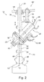
- the machine holder 34 is raised and lowered by motor and possibly provided with an additional torque support (see also Fig. 2 ) to ensure an exact spatial positioning of the holding and / or centering elements 18.
- These can in turn be equipped with various attachments such as, for example, holding bells, suction elements, stamps, etc.
- the two centering elements 18 shown each have differently sized centering bells 24, which are arranged on a largely identically designed and dimensioned shaft portion 26.
- the centering bell 24 located in the current operating position is slightly conically elongated, while the centering bell 24, which is in the rest position, has a flatter design and is dish-shaped.
- FIG. 2 The in the schematic sectional view of Fig. 2 shown further embodiment of the inventive device 10 for handling and / or treatment of containers 12 differs in some details from the in Fig. 1 shown first variant. These essential differences are explained in detail below, while other equipment details that match the first variant, are not or only briefly explained, as in this context to the above description of Fig. 1 can be referenced.
- FIG. 2 This is how the in Fig. 2 shown and aligned in the vertical direction with the longitudinal axis 20 centering 18 no centering bell, but a conical countersunk 46, which may optionally have an elastic surface to the seal against the container mouth 14, in which it can be sunk (see the in Fig. 2 to ensure and / or improve the state shown).
- the conical countersunk head 46 of the centering element 18 also has a central air bore 48, the mouth 50 is centrally located in the tip of the countersunk head 46, so that the interior of the container 12 can be set under pressure or optionally negative pressure. Normally, a slight overpressure is introduced into flexible plastic containers 12 via the air bore 48, while these are labeled and / or printed, in order in this way to stabilize the outer jacket surface and to optimize the printed image or the labeling process.
- the central air bore 48 is guided not only by the shaft portion 26 and the mounting pin 28, but also in the interior of the holding device 22 via the corresponding threaded bore 44.
- the air bore 48 initially runs vertically along the longitudinal axis 20 until it reaches the pivot axis 36 of the holding device 22, which hits the central vertical longitudinal axis of the device holder 34 at an angle of 45 degrees.
- a further lateral line connection 58 may optionally serve to supply another, not shown, centering element 18, for which purpose a separate air line to one of the other threaded holes 44 is required, which is guided through the interior of the holding device 22.
- the variant of the Fig. 2 an optional motorized adjustment of the holding device.
- the locking pin 42 is provided for unlocking and locking the holding device 22 in its various angular positions with a pneumatic actuator 60, which may be connected via two control lines with a controllable compressed air supply (not shown).
- a pneumatic actuator 60 By the pneumatic actuation of the actuator 60 and the cooperating locking bolt 42, the rotation of the lower mushroom-like widening 38 can be initiated by the 45 degrees inclined pivot axis 36, which either manually - by operating the rotary knob 40 - or by motor activation - eg. By Electric motor or air motor o. The like. - Can be done.
- Such a servomotor can be integrated in the axle receptacle 32.
- the torque support 62 includes at least one lateral lever 64 supported by an axle anchor 66 on an upper bracket 68, the axle anchor 66 being disposed parallel to the longitudinal axis 20 and the additional lateral lever 64 having a horizontal longitudinal extension direction.
- FIGS. 1 and 2 show, on the holding device, which, for example. Includes a rotatable turret, up to six shots for different Centering be arranged.
- the revolver is rotatably mounted by hand and can be fixed, for example, via a locking element in a desired position (see Fig. 1 ).
- the turret can also be rotated via a suitable actuator and, for example, be fixed in the selected rotational position or operating position via a pneumatically operated plunger (see Fig. 2 ).
- an actuator such as an electromotive adjustment drive.
- this embodiment is not shown here in detail.
- FIGS. 1 and 2 described aspects of an embodiment of the container treatment apparatus 10 also relate to the inventive method for holding, gripping and / or rotating standing on a support of the container handling device 10 containers 12.
Abstract
Die Erfindung betrifft eine Behälterhandhabungsvorrichtung (10) zum Halten, Greifen und/oder Drehen von auf einer Auflage stehenden Behältern (12) an ihrer oberen Mündung (14) und/oder an ihrem Halsbereich. Die Vorrichtung (10) weist wenigstens zwei vertikal verstellbare und/oder eine vertikale Haltekraft übertragende Halte- und/oder Zentrierelemente (18) auf, die wechselweise zwischen einer Betriebslage und einer Ruhelage verstellbar sind, so dass das jeweils in Betriebslage befindliche Halte- und/oder Zentrierelement (18) in Eingriff mit einem Behälter (12) bringbar ist. Die wenigstens zwei Halte- und/oder Zentrierelemente (18) sind an einer gemeinsamen Halteeinrichtung (22) angeordnet, durch deren Rotation um einen definierten Schwenkwinkel jedes daran befindliche Halte- und/oder Zentrierelement (18) zwischen seiner Betriebs- und Ruhelage verschwenkbar ist. Die Erfindung betrifft zudem ein Verfahren zum Halten, Greifen und/oder Drehen von auf einer Auflage einer solchen Behälterhandhabungsvorrichtung (10) stehenden Behältern (12).The invention relates to a container handling device (10) for holding, gripping and / or rotating resting on a container containers (12) at its upper mouth (14) and / or at its neck region. The device (10) has at least two vertically adjustable and / or a vertical holding force transmitting holding and / or centering elements (18) which are alternately adjustable between an operating position and a rest position, so that each located in the operating position holding and / or centering element (18) into engagement with a container (12) can be brought. The at least two holding and / or centering elements (18) are arranged on a common holding device (22), by the rotation about a defined pivot angle each holding and / or centering element (18) is pivotable between its operating and rest position. The invention also relates to a method for holding, gripping and / or rotating containers (12) standing on a support of such a container handling device (10).
Description
Die vorliegende Erfindung betrifft eine Behälterhandhabungsvorrichtung zum Halten, Greifen und/oder Drehen von auf einer Auflage stehenden Behältern an ihrer oberen Mündung und/oder an ihrem Halsbereich mit den Merkmalen des unabhängigen Anspruchs 1. Die Erfindung betrifft zudem ein Verfahren zum Halten, Greifen und/oder Drehen von auf einer Auflage einer solchen Behälterhandhabungsvorrichtung stehenden Behältern mit den Merkmalen des unabhängigen Verfahrensanspruchs 14.The present invention relates to a container handling device for holding, gripping and / or rotating containers on a support at its upper mouth and / or at its neck region with the features of independent claim 1. The invention also relates to a method for holding, gripping and / or or rotating containers standing on a support of such a container handling device with the features of
Mit der vorliegenden Erfindung wird ein sog. Zentrierkopf zur Verfügung gestellt, der oberseitig an einem Gefäß oder einem Behälter angreift, welcher auf einer Auflage wie bspw. einem Drehteller steht. Der Zentrierkopf ist normalerweise Teil einer komplexeren Behälterbehandlungsmaschine und dient dem axialen Einspannen eines von mehreren in der Maschine befindlichen und jeweils auf separaten Drehteller stehenden Behälters. Der erfindungsgemäße Zentrierkopf weist einen wechselbaren Revolverkopf mit unterschiedlichen Zentrierglocken und/oder -einsätzen auf.With the present invention, a so-called. Centering head is provided which engages on the upper side of a vessel or a container, which stands on a support such as a turntable. The centering head is normally part of a more complex container treatment machine and serves for axially clamping one of a plurality of containers located in the machine and each on a separate turntable. The centering head according to the invention has a replaceable turret with different centering bells and / or inserts.
Ähnliche Vorrichtungen dieser Art werden üblicherweise in Behälter- oder Gefäßbehandlungsmaschinen wie bspw. in Etikettier-, Inspektion- oder Druckmaschinen zum Fixieren der auf Drehtellern aufrecht stehenden Flaschen, Dosen oder dgl. Behältern eingesetzt. Durch eine axiale Abstandsverringerung können Gefäße oder Behälter zwischen dem Drehteller und dem axial fluchtend zugeordneten Zentrierkopf drehbar eingespannt werden. Die bislang verwendeten Zentrierköpfe sind normalerweise einstückig ausgeführt, wie dies bspw. die
Bei bekannten Behälterbehandlungsvorrichtungen werden in Rundläufermaschinen mit darin angeordneten bzw. diesen zugeordneten Etikettiervorrichtungen, Füllvorrichtungen oder Behälterinspektionsvorrichtungen die zu behandelnden Behälter meist auf einem Karussell angeordnet und jeweils auf einem Flaschenteller platziert und dort mittels die Behälter von oben fixierenden Greifvorrichtungen drehbar gehalten. Die Greifvorrichtungen sind meist durch federvorgespannte Elemente wie bspw. Zentrierglocken gebildet, die die Behälter beim Bewegen durch die Maschine halten und auf dem Drehteller fixieren.In known container treatment devices are arranged in rotary machines with therein or associated therewith labeling, filling or Behälterinspektionsvorrichtungen the container to be treated usually on a carousel and placed each on a bottle plate and held rotatably there by means of the container from above fixing gripping devices. The gripping devices are usually formed by spring-biased elements such as. Centering, which hold the container when moving through the machine and fix it on the turntable.
Derartige Halteeinrichtungen sind bspw. aus der
Nachteilig erweisen sich die aus dem Stand der Technik bekannten Einrichtungen, wenn unterschiedliche Gebinde oder Behälter mit unterschiedlichen und/oder voneinander abweichenden Mündungen verwendet werden bzw. auf den Drehtellern fixiert werden sollen, da hierbei die Zentrierglocken per Hand gegen jeweils zur abweichenden Mündungsform und/oder -größe passende Aufsätze oder Zentrierglocken ausgetauscht werden müssen.Disadvantages prove to be the devices known from the prior art, if different containers or containers are used with different and / or divergent mouths or should be fixed on the turntables, since in this case the centering by hand against each other to the different mouth shape and / or size matching essays or centering must be replaced.
Ein erstes Ziel der vorliegenden Erfindung besteht darin, einen universell verwendbaren Zentrierkopf zur Verfügung zu stellen, der durch eine Eignung für unterschiedliche Behälterformen und/oder -größen eine hohe Flexibilität im Betrieb aufweist und es ermöglicht, die Rüstzeiten bei der Umstellung auf andere Behälterformen und/oder Behältergrößen zu reduzieren.A first object of the present invention is to provide a universally usable centering head which has high flexibility in operation through suitability for different container shapes and / or sizes, and allows setup times to be changed to other container shapes and / or sizes. or to reduce container sizes.
Das Ziel der Erfindung wird mit dem Gegenstand des unabhängigen Anspruchs 1 erreicht. Merkmale vorteilhafter Weiterbildungen der Erfindung finden sich in den abhängigen Ansprüchen sowie in der weiteren Beschreibung.The object of the invention is achieved with the subject matter of independent claim 1. Features of advantageous developments of the invention can be found in the dependent claims and in the further description.
Zur Erreichung des genannten Ziels schlägt die Erfindung eine Vorrichtung zur Handhabung und/oder Behandlung von Behältern mit den Merkmalen des unabhängigen Anspruchs 1 vor. Die Vorrichtung ist vorbereitet und ausgestattet zum Halten, Greifen und/oder Drehen von auf einer Auflage stehenden Behältern an ihrer oberen Mündung und/oder an ihrem Halsbereich und umfasst wenigstens zwei vertikal verstellbare und/oder eine vertikale Haltekraft übertragende Halte- und/oder Zentrierelemente, die wechselweise zwischen einer Betriebslage und einer Ruhelage verstellbar sind, so dass das jeweils in Betriebslage befindliche Halte- und/oder Zentrierelement in Eingriff mit einem Behälter bringbar ist. Weiterhin ist vorgesehen, dass die wenigstens zwei Halte- und/oder Zentrierelemente an einer gemeinsamen Halteeinrichtung angeordnet sind, durch deren Rotation um einen definierten Schwenkwinkel jedes daran befindliche Halte- und/oder Zentrierelement zwischen seiner Betriebs- und Ruhelage verschwenkbar ist. Die Halteeinrichtung kann zur Fixierung eines auf der Auflage bzw. einem Drehteller stehenden Behälters variabel in vertikaler Richtung abgesenkt werden, vorzugsweise in unterschiedliche Höhenniveaus, damit unterschiedlich große Behälter gleichermaßen gehalten werden können. Bei der Auflage handelt es sich üblicherweise um Drehteller, die der drehbaren Aufnahme jeweils eines Behälters dienen. Mehrere solcher Drehteller mit zugehörigen Halte- und/oder Fixiereinrichtungen bzw. Zentrierelementen können am äußeren Umfang eines drehbaren Maschinenteils angeordnet sein, die Teil einer komplexeren Behälterbehandlungs- und/oder -handhabungsmaschine sein kann.To achieve the stated object, the invention proposes a device for handling and / or treating containers with the features of independent claim 1. The device is prepared and equipped for holding, gripping and / or rotating containers standing on a support at its upper mouth and / or at its neck region and comprises at least two holding and / or centering elements which can be vertically adjusted and / or transmit a vertical holding force, which are alternately adjustable between an operating position and a rest position, so that each holding in the operating position holding and / or centering element can be brought into engagement with a container. It is further provided that the at least two holding and / or centering elements are arranged on a common holding device, by its rotation about a defined pivot angle each holding and / or centering element is pivotable between its operating and rest position. The holding device can be lowered for fixing a standing on the support or a turntable container variable in the vertical direction, preferably in different height levels, so that different sized containers alike can be kept. The edition is usually turntable, which serve the rotatable receiving a respective container. Several such turntables with associated holding and / or fixing devices or centering elements may be arranged on the outer circumference of a rotatable machine part, which may be part of a more complex container handling and / or handling machine.
Um den Behälter wieder freizugeben, kann die Halteeinrichtung wieder in vertikaler Richtung angehoben werden, wodurch der Hals- oder Mündungsbereich des Behälter freigegeben wird und der Behälter von der Auflage entnommen werden kann. Die wenigstens zwei Halte- und/oder Zentrierelemente sind an der gemeinsamen Halteeinrichtung gelagert, so dass das jeweils in Betriebslage befindliche Halte- und/oder Zentrierelement von oben durch vertikales Absenken mit dem Hals- oder Mündungsbereich des auf der Auflage stehenden Behälters in Eingriff gebracht werden kann, während das jeweils aus dem Eingriffsbereich mit dem Behälter geschwenkte oder gedrehte und damit in Ruhelage befindliche Halte- und/oder Zentrierelement in seitlicher Richtung orientiert ist, wo es weder mit dem Behälter kollidieren noch mit einem benachbarten Behälter oder Halteelement einer unmittelbar benachbarten Behälterposition kollidieren oder in Berührung kommen kann.To release the container again, the holding device can be raised again in the vertical direction, whereby the neck or mouth region of the container is released and the container can be removed from the support. The at least two holding and / or centering elements are mounted on the common holding device, so that each holding in the operating position holding and / or centering element are brought from above by vertical lowering with the neck or mouth region of the container standing on the support can, while the respectively pivoted from the engagement area with the container or rotated and thus in rest position holding and / or centering is oriented in the lateral direction where it does not collide with the container nor collide with an adjacent container or holding element of an immediately adjacent container position or come into contact.
Bei einer vorteilhaften Variante der erfindungsgemäßen Behälterhandhabungsvorrichtung ist die Halteeinrichtung an einem Maschinenhalter drehbar gelagert, der wiederum vorzugsweise um eine vertikale Drehachse rotierbar ist, so dass er insbesondere mit drehbar gelagerten Auflagen bzw. Drehtellern zusammenwirken kann, auf denen die Behälter mit ihrer Unterseite stehen, so dass durch eine gesteuerte motorische Drehung des Maschinenhalters um einen vorgebbaren Drehwinkel eine entsprechende Positionierung des Behälters bzw. Gefäßes ermöglicht ist. Die am Maschinenhalter rotierbar gelagerte Halteeinrichtung kann insbesondere eine Dreh- oder Schwenkachse aufweisen, die um ca. 45 Grad gegenüber der Vertikalen geneigt ist, wodurch die jeweiligen Halte- und/oder Zentriereinrichtungen in die Betriebslage oder in die Ruhelage bringbar sind, ohne dass hierzu große Verschwenkoder Verfahrwege erforderlich sind. Durch die um 45 Grad geneigte Schwenkachse ist eine Art Revolvermagazin gebildet, das mehrere unterschiedlich geformte und dimensionierte Halte- bzw. Zentriereinrichtungen zur Verfügung stellen kann, von denen sich immer nur jeweils eine in Betriebslage befindet, bei der sie eine vertikal stehende Längserstreckungs- und Wirkrichtung zum jeweiligen Behälter aufweist, der auf der Auflage bzw. auf dem Drehteller steht, während die jeweils anderen Halte- bzw. Zentriereinrichtungen in eine Ruhelage gebracht sind, bei der ihre Längserstreckungsrichtung bspw. horizontal oder in einem anderen Winkel liegen kann.In an advantageous variant of the container handling device according to the invention, the holding device is rotatably mounted on a machine holder, which in turn is preferably rotatable about a vertical axis of rotation, so that it can interact in particular with rotatably mounted supports or turntables on which the containers are with their underside, so that a corresponding positioning of the container or vessel is made possible by a controlled motor rotation of the machine holder to a predeterminable angle of rotation. The holder rotatably mounted on the machine holder may in particular have a pivot or pivot axis which is inclined by approximately 45 degrees relative to the vertical, whereby the respective holding and / or centering devices can be brought into the operating position or in the rest position, without requiring large Pivoting or travel paths are required. Due to the tilted by 45 degrees pivot axis a kind of revolving magazine is formed, which can provide several differently shaped and dimensioned holding or centering available, of which there is only one in each operating position, in which they have a vertically extending longitudinal extension and effective direction to the respective container which stands on the support or on the turntable, while the other respective holding or Centering devices are brought into a rest position, in which their longitudinal direction, for example, can be horizontal or at a different angle.
Bei einer weiteren bevorzugten Ausführungsvariante der erfindungsgemäßen Behälterhandhabungsvorrichtung können die jeweiligen Längsachsen der wenigstens zwei Halte- und/oder Zentrierelemente, die an der gemeinsamen Halteeinrichtung fixiert sind, die Dreh- oder Schwenkachse der rotierbaren Halteeinrichtung jeweils vorzugsweise in einem Winkel von etwa 45 Grad schneiden, wodurch der oben erwähnte revolverähnliche Verstellmechanismus gebildet ist, der eine sehr schnelle Umrüstung ermöglicht, ohne dass hierzu manuelle Eingriffe oder ein Austauschen von Teilen erforderlich wären. Wenn zudem die Halteeinrichtung in mehreren Raststufen um ihre Längsachse verdrehbar ist, kann eine schnelle manuelle Umschaltung zwischen Ruheund Betriebslage durch entsprechendes Verschwenken der Halteeinrichtung um die schräge, insbesondere um 45 Grad schräg gestellte Dreh- oder Schwenkachse erreicht werden. Die Raststufen können vorteilhafterweise jeweils Gradeinteilungen von bspw. ca. 60 Grad oder auch von ca. 90 Grad oder von ca. 120 Grad aufweisen. Auch andere Gradeinteilungen sind denkbar, ggf. auch mit voneinander abweichenden Winkelunterteilungen.In a further preferred embodiment of the container handling device according to the invention, the respective longitudinal axes of the at least two holding and / or centering elements, which are fixed to the common holding device, respectively cut the rotary or pivot axis of the rotatable holding device at an angle of about 45 degrees, respectively the above-mentioned revolver-like adjustment mechanism is formed, which allows a very fast conversion, without the need for manual intervention or replacement of parts would be required. In addition, if the holding device is rotatable about its longitudinal axis in several latching steps, a fast manual switch between rest and operating position can be achieved by corresponding pivoting of the holding device to the inclined, in particular inclined by 45 degrees rotational or pivot axis. The latching steps can advantageously each have graduations of, for example, about 60 degrees or even about 90 degrees or about 120 degrees. Other graduations are conceivable, possibly also with divergent angular divisions.
Die erfindungsgemäße Ausgestaltung der Behälterhandhabungsvorrichtung ermöglicht auch weitere Ausstattungsmerkmale, so dass die Halte- und/oder Zentrierelemente bspw. jeweils mit einer zentralen Luftleitung oder Luftdurchführung ausgestattet sein können, die sich in integrierter Bauweise jeweils durch die Halteeinrichtungen bis zum Maschinenhalter führen lassen. Auch Luftführungen bis zur Halteeinrichtung unter Umgehung der zentralen Maschinenhalterung sind denkbar, wobei an der Halteeinrichtung geeignete Leitungsanschlüsse für flexible Luftleitungen angebracht sein können. Diese Luftleitungen können besonders vorteilhaft zur Zuführung von sterilisierter Luft in den Behälter genutzt werden, was bspw. bei Anordnungen in steriler Umgebung bzw. im Reinraum von Vorteil ist. So können die Luftleitungen wahlweise genutzt werden, dem Behälter Sterilluft zuzuführen.The inventive design of the container handling device also allows further equipment features, so that the holding and / or centering elements, for example, each may be equipped with a central air line or air duct, which can be performed in integrated design in each case by the holding devices to the machine holder. Also, air ducts to the holding device, bypassing the central machine holder are conceivable, which can be attached to the holding device suitable line connections for flexible air ducts. These air lines can be used particularly advantageously for supplying sterilized air into the container, which is advantageous, for example, in arrangements in a sterile environment or in a clean room. Thus, the air lines can optionally be used to supply the container sterile air.
Ein weiterer Vorteil der Anordnung ist die besonders kompakte Bauweise, die sich vorteilhaft in steriler Umgebung auswirkt. So ist eine solche kompakte Bauweise besonders vorteilhaft, wenn eine Behälterbehandlungsvorrichtung im sog. Reinraum arbeitet.Another advantage of the arrangement is the particularly compact design, which has an advantageous effect in a sterile environment. Thus, such a compact design is particularly advantageous when a container treatment device operates in the so-called. Clean room.
Wahlweise kann bei der Behälterhandhabungsvorrichtung vorgesehen sein, dass sich die wenigstens zwei an der gemeinsamen Halteeinrichtung angeordneten Halte- und/oder Zentrierelemente jeweils zwischen ihrer Betriebslage und ihrer Ruhelage manuell verstellen lassen. Ebenso kann in alternativer Ausführung vorgesehen sein, dass sich die wenigstens zwei an der gemeinsamen Halteeinrichtung angeordneten Halte- und/oder Zentrierelemente jeweils zwischen ihrer Betriebslage und ihrer Ruhelage motorisch, insbesondere elektromotorisch verstellen lassen. Weiterhin kann es von Vorteil sein, wenn der Maschinenhalter motorisch heb- und senkbar ist und ggf. mit einer zusätzlichen Drehmomentabstützung versehen ist, um eine exakte räumliche Positionierung der Halte- und/oder Zentrierelemente zu gewährleisten. Diese können wiederum mit verschiedenen Anbauteilen wie bspw. Halteglocken, Saugelementen, Stempel etc. ausgestattet sein.Optionally, it may be provided in the container handling device that the at least two holding and / or centering elements arranged on the common holding device can each be adjusted manually between their operating position and their rest position. Likewise, it can be provided in an alternative embodiment that the at least two holding and / or centering elements arranged on the common holding device can be adjusted by motor, in particular by an electric motor, between their operating position and their rest position. Furthermore, it may be advantageous if the machine holder is raised and lowered by a motor and optionally provided with an additional torque support to ensure an exact spatial positioning of the holding and / or centering. These can in turn be equipped with various attachments such as, for example, holding bells, suction elements, stamps, etc.
Die vorliegende Erfindung kann auch dadurch charakterisiert werden, dass sie eine äußerst variabel an verschiedene Behälterformen, -konturen und -größen anpassbare Halteeinrichtung vorschlägt, die bspw. einen drehbaren Revolverkopf mit vorzugsweise bis zu sechs Aufnahmen für unterschiedliche Zentrierglocken aufweisen kann. Im einfachsten Fall ist der Revolver über Hand drehbar gelagert und kann bspw. über ein Rastelement in einer gewünschten Lage fixiert werden. Anstelle von Hand kann der Revolver auch über einen geeigneten Aktuator gedreht und bspw. über einen pneumatisch arbeitenden Stößel in der gewählten Drehlage bzw. Betriebslage fixiert werden. Weiterhin denkbar ist eine Abfrage der aktuell gewählten Stößelposition über einen Initiator oder sonstige Sensoreinheit, um die gewünscht Position sicher zu stellen und die Ansteuerung durch einen Aktuator wie bspw. einen elektromotorischen Verstellantrieb zu erleichtern.The present invention can also be characterized in that it proposes a holding device that is extremely variable in adaptable to different container shapes, contours and sizes, which can, for example, have a rotatable turret with preferably up to six receptacles for different centering bells. In the simplest case, the revolver is rotatably mounted by hand and can be fixed, for example, via a locking element in a desired position. Instead of hand, the turret can also be rotated via a suitable actuator and, for example, be fixed via a pneumatically operated plunger in the selected rotational position or operating position. It is also conceivable to query the currently selected plunger position via an initiator or other sensor unit in order to ensure the desired position and to facilitate actuation by an actuator, such as an electromotive adjustment drive.
Herkömmliche Maschinen in Standardausführung können Behälter, Flaschen bzw. Gebinde in typischen Höhen von ca. 50 bis 280 mm, von ca. 150 bis 380 mm oder von ca. 250 bis 480 mm verarbeiten. Je nach der jeweiligen Höhe der Behälter, Flaschen bzw. Gebinde werden die sog. Mittelwelle und die Höhenverstellung der Maschinen ausgelegt. Ebenfalls denkbar ist eine unterschiedliche Auslegung der Zentrierkopflänge "L", um damit bspw. auch Behälter, Flaschen bzw. Gläser verarbeiten zu können, deren Höhe weniger als 150 mm beträgt. Weiterhin werden insbesondere Kunststoffgebinde oder -behälter, die leer etikettiert werden, mit einer vorherigen Aufblasung beaufschlagt. Dabei könnte eine Zentrierglocke mit einem Luftanschluss versehen werden, wogegen eine nachfolgende oder weitere Glocke keinen solchen Luftanschluss aufweisen muss. Weiterhin ist es sinnvoll, Kunststoffflaschen, insbesondere Leerflaschen mit Aufblasung mit einer geringeren Federkraft vom Zentrierkopf zu beaufschlagen. Bei Glasflaschen werden vorzugsweise Druckfedern mit einer Federrate von ca. 18 kg eingesetzt, während bei Kunststofflaschen typischerweise Federn mit einer Federrate von ca. 6 kg verwendet werden können. Darüber hinaus ist es denkbar, einen Zentrierkopf bei Kunststoffflaschen mit einer Federrate von 6 kg zu verwenden und bei Einsatz von Glasflaschen auf eine Glocke mit Zusatzfedern umzustellen, um auf eine Gesamtfederrate von 18 kg zu kommen. Vorteilhafterweise hat der Revolverkopf eine Drehmomentstützung und ein gefedertes Druckstück, um eine Vorarretierung bei der Umstellung zu erhalten.Conventional machines in standard design can process containers, bottles or containers at typical heights of approx. 50 to 280 mm, approx. 150 to 380 mm or approx. 250 to 480 mm. Depending on the respective height of the containers, bottles or containers, the so-called. Medium wave and the height adjustment of the machines are designed. Also conceivable is a different interpretation of Zentrierkopflänge "L", so as to be able to process, for example, containers, bottles or glasses whose height is less than 150 mm. Furthermore, in particular plastic containers or containers that are labeled empty, subjected to a previous inflation. In this case, a centering bell could be provided with an air connection, whereas a subsequent or further bell need not have such an air connection. Furthermore, it makes sense plastic bottles, especially empty bottles with inflation with a To apply lower spring force from the centering. For glass bottles, compression springs are preferably used with a spring rate of about 18 kg, while plastic bottles typically springs with a spring rate of about 6 kg can be used. In addition, it is conceivable to use a centering head for plastic bottles with a spring rate of 6 kg and to switch to a bell with additional springs when using glass bottles in order to achieve a total spring rate of 18 kg. Advantageously, the turret has a torque support and a sprung pressure piece to obtain a Vorarretierung during the changeover.
Ein weiteres Ziel der vorliegenden Erfindung besteht darin, ein universell verwendbares Verfahren zur Behälterbehandlung zur Verfügung zu stellen, das durch seine Anwendbarkeit auf unterschiedliche Behälterformen und/oder -größen eine hohe Flexibilität im Betrieb aufweist und das es ermöglicht, die Rüstzeiten bei der Umstellung auf andere Behälterformen und/oder Behältergrößen zu reduzieren.A further object of the present invention is to provide a universally applicable container treatment method which, by being applicable to different container shapes and / or sizes, has a high flexibility in operation and which enables set-up times to be converted to others To reduce container shapes and / or container sizes.
Dieses weitere Ziel der Erfindung wird mit dem Gegenstand des unabhängigen Verfahrensanspruchs 14 erreicht. So schlägt die Erfindung zur Erreichung des genannten weiteren Ziels ein Verfahren zum Halten, Greifen und/oder Drehen von auf einer Auflage einer Behälterhandhabungsvorrichtung stehenden Behältern an ihrer jeweiligen oberen Mündung und/oder an ihrem Halsbereich vor, das die folgenden Merkmale aufweist. Bei dem erfindungsgemäßen Verfahren werden wenigstens zwei vertikal verstellbare und/oder eine vertikale Haltekraft übertragende Halte- und/oder Zentrierelemente wechselweise zwischen einer Betriebslage und einer Ruhelage verstellt bzw. wechselweise in eine Betriebslage oder eine Ruhelage gebracht, so dass das jeweils in Betriebslage befindliche Halte- und/oder Zentrierelement in Eingriff mit einem Behälter gebracht wird, der auf der Auflage steht. Die wenigstens zwei Halte- und/oder Zentrierelemente sind derart an einer gemeinsamen Halteeinrichtung angeordnet sind, dass durch deren Rotation um einen definierten Schwenkwinkel jedes daran befindliche Halte- und/oder Zentrierelement jeweils zwischen seiner Betriebs- und Ruhelage verschwenkt werden kann.This further object of the invention is achieved with the subject matter of
Weitere Varianten und Vorteile des erfindungsgemäßen Verfahrens ergeben sich aus den bereits zuvor beschriebenen Aspekten zu den verschiedenen Ausführungsvarianten der erfindungsgemäßen Behälterbehandlungsanlage. Diese beziehen sich allesamt auch auf das erwähnte Verfahren.Further variants and advantages of the method according to the invention emerge from the aspects already described above relating to the different embodiments of the container treatment system according to the invention. All these also refer to the mentioned method.
Im Folgenden sollen Ausführungsbeispiele die Erfindung und ihre Vorteile anhand der beigefügten Figuren näher erläutern. Die Größenverhältnisse der einzelnen Elemente zueinander in den Figuren entsprechen nicht immer den realen Größenverhältnissen, da einige Formen vereinfacht und andere Formen zur besseren Veranschaulichung vergrößert im Verhältnis zu anderen Elementen dargestellt sind.
-
Fig. 1 zeigt eine schematische Ansicht einer ersten Ausführungsvariante einer mehrteiligen verstellbaren Halteeinrichtung für mehrere Zentrierelemente, die zur oberen Abstützung von Behältern vorgesehen sind, die auf unteren Aufnahmen oder Drehtellern stehen. -
Fig. 2 zeigt eine schematische Ansicht einer zweiten Ausführungsvariante der Halteeinrichtung für mehrere Zentrierelemente.
-
Fig. 1 shows a schematic view of a first embodiment of a multi-part adjustable holding device for a plurality of centering elements, which are provided for upper support of containers that are on lower receptacles or turntables. -
Fig. 2 shows a schematic view of a second embodiment of the holding device for a plurality of centering elements.
Für gleiche oder gleich wirkende Elemente der Erfindung werden identische Bezugszeichen verwendet. Ferner werden der Übersicht halber nur Bezugszeichen in den einzelnen Figuren dargestellt, die für die Beschreibung der jeweiligen Figur erforderlich sind. Die dargestellten Ausführungsformen stellen lediglich Beispiele dar, wie die erfindungsgemäße Vorrichtung oder das erfindungsgemäße Verfahren ausgestaltet sein können und stellen keine abschließende Begrenzung dar.For identical or equivalent elements of the invention, identical reference numerals are used. Furthermore, for the sake of clarity, only reference symbols are shown in the individual figures, which are required for the description of the respective figure. The illustrated embodiments are merely examples of how the device or method of the invention may be configured and are not an exhaustive limitation.
Die schematische Detailansicht der
Wie es die
Die beiden Zentrierelemente 18 sind jeweils als Zentrierglocken 24 ausgebildet, deren breiterer unterer schirmartiger Zentrierabschnitt die Mündung 14 des Behälters 12 umgreifen und damit sicher halten kann, wenn er darauf aufgesetzt wird. Oberhalb der Zentrierglocken 24 schließt sich jeweils ein hohlzylindrischer Schaftabschnitt 26 an, der zur lösbaren Befestigung des Zentrierelements 18 an einem entsprechend dimensionierten Befestigungszapfen 28 weitgehend spielfrei auf diesen aufgeschoben werden und über einen Klemmhebel 30 geklemmt und fixiert werden kann.The two centering
Die beiden zylindrischen Befestigungszapfen 28, deren Außendurchmesser jeweils dem Innendurchmesser der Mittenbohrungen der beiden hohlzylindrischen Schaftabschnitte 26 der jeweiligen Zentrierelemente 18 entspricht, sind an der verdrehbaren Halteeinrichtung 22 verankert, die zweiteilig ausgebildet ist. Eine Achsaufnahme 32 ist mit dem vertikal (Pfeilrichtung 16) verstellbaren und um die vertikale Längsachse 20 verdrehbaren Vorrichtungshalter 34 fest verbunden, so dass sie gemeinsam mit diesem sowohl gehoben und gesenkt als auch um die Achse 20 verdreht wird. Die an der Unterseite des Vorrichtungshalters 34 angeordnete Achsaufnahme 32 trägt und lagert eine um ca. 45 Grad zur vertikalen Längsachse 20 geneigte und diese in dem 45°-Winkel schneidende Schwenkachse 36 mit schräg nach unten weisender pilzartiger Verbreiterung 38 mit konischer Außenmantelfläche, welche die beiden Befestigungszapfen 28 trägt und mittig zur Achse 36 einen ebenfalls schräg nach unten weisenden und zur manuellen Verstellung leicht zugänglichen Drehknebel 40 aufweist.The two cylindrical mounting pins 28, the outer diameter of which corresponds in each case to the inner diameter of the central bores of the two hollow
Rückseitig der pilzartigen Verbreiterung 38 trägt die Achsaufnahme 32 einen axial verstellbaren Verriegelungsbolzen 42, der im verriegelten Zustand in die rückseitige Stirnfläche der pilzartigen Verbreiterung 38 eingreift und somit eine Verdrehung der Schwenkachse 36 innerhalb der Achsaufnahme 32 blockiert. Wird der Verriegelungsbolzen 42 dagegen durch Verdrehen oder manuellen axialen Zug nach schräg oben entriegelt, kann durch manuelles Verdrehen am zentralen Drehknebel 40 die gesamte Verbreiterung 38 mitsamt den an der Verbreiterung 38 gehaltenen Zentrierelementen 18 um die Schwenkachse 36 verdreht werden, wodurch gleichzeitig die Zentrierelemente 18 zwischen einer Betriebslage und einer Ruhelage verschwenkt werden können. So kann nach manueller Betätigung des Verriegelungsbolzens 42 und manuellem Drehen am Drehknebel 40 die Halteeinrichtung 22 bspw. um 180 Grad verdreht werden, was einen Austausch der Positionen der beiden Zentrierelemente 18 bewirkt, da diese an jeweils gegenüberliegenden und damit um 180 Grad versetzten Positionen an der konischen Außenmantelfläche der pilzartigen Verbreiterung 38 der Halteeinrichtung 22 angeordnet und fixiert sind.On the back of the mushroom-like widening 38, the
Die
Wie es die in
Wie erwähnt, kann die Halteeinrichtung 22 zur Fixierung eines auf der Auflage oder dem Drehteller stehenden Behälters 12 variabel in vertikaler Richtung 16 abgesenkt werden, vorzugsweise in unterschiedliche Höhenniveaus, damit unterschiedlich große Behälter 12 gleichermaßen gehalten werden können. Bei der Auflage handelt es sich üblicherweise um Drehteller, die der drehbaren Aufnahme jeweils eines Behälters 12 dienen. Mehrere solcher Drehteller mit zugehörigen Halte- und/oder Fixiereinrichtungen bzw. Zentrierelementen 18 können am äußeren Umfang eines drehbaren Maschinenteils angeordnet sein, die Teil einer komplexeren Behälterbehandlungs- und/oder Behälterhandhabungsmaschine (nicht dargestellt) sein kann. Um den Behälter 12 wieder freizugeben, kann die Halteeinrichtung 22 entlang der vertikalen Längsachse 20 wieder in vertikaler Richtung angehoben werden, wodurch der Hals- oder Mündungsbereich 14 des Behälters 12 freigegeben wird und der Behälter 12 von der Auflage entnommen werden kann. Die wenigstens zwei Halte- und/oder Zentrierelemente 18 sind an der gemeinsamen Halteeinrichtung 22 gelagert und fixiert, so dass das jeweils in Betriebslage befindliche Halte- und/oder Zentrierelement 18 von oben durch vertikales Absenken mit dem Hals- oder Mündungsbereich 14 des auf der Auflage stehenden Behälters 12 in Eingriff gebracht werden kann, während das jeweils aus dem Eingriffsbereich mit dem Behälter 12 geschwenkte oder gedrehte und damit in Ruhelage befindliche Halte- und/oder Zentrierelement 18 in seitlicher Richtung orientiert ist, wo es weder mit dem Behälter 12 kollidieren noch mit einem benachbarten Behälter 12 oder Halteelement einer unmittelbar benachbarten Behälterposition kollidieren oder in Berührung kommen kann.As mentioned, the holding
Wahlweise kann bei der Behälterhandhabungsvorrichtung 10 gemäß
Die in der schematischen Schnittansicht der
So weist das in
Wie es die
Weiterhin zeigt die Variante der
Weiterhin zeigt die Variante der
Wie es die
Rein vorsorglich sei an dieser Stelle nochmals erwähnt, dass alle mit Bezugnahme auf die
Die Erfindung wurde unter Bezugnahme auf eine bevorzugte Ausführungsform beschrieben. Es ist jedoch für einen Fachmann vorstellbar, dass Abwandlungen oder Änderungen der Erfindung gemacht werden können, ohne dabei den Schutzbereich der nachstehenden Ansprüche zu verlassen.The invention has been described with reference to a preferred embodiment. However, it will be apparent to those skilled in the art that modifications or changes may be made to the invention without departing from the scope of the following claims.
- 1010
- Vorrichtung, Vorrichtung zur Handhabung und/oder Behandlung von BehälternDevice, device for handling and / or treating containers
- 1212
- Behältercontainer
- 1414
- Mündung, BehältermündungMouth, container mouth
- 1616
- Vertikalrichtung, vertikale VerstellbarkeitVertical direction, vertical adjustability
- 1818
- Zentrierelementcentering
- 2020
- Längsachse, DrehachseLongitudinal axis, axis of rotation
- 2222
- Halteeinrichtungholder
- 2424
- Zentrierglockecentering
- 2626
- Schaftabschnittshank portion
- 2828
- Befestigungszapfenfastening pins
- 3030
- Klemmhebelclamping lever
- 3232
- Achsaufnahmeaxle mount
- 3434
- Vorrichtungshalterdevice holder
- 3636
- Schwenkachse, geneigte SchwenkachseSwivel axis, inclined swivel axis
- 3838
- Verbreiterung, pilzartige VerbreiterungWidening, mushroom-like widening
- 4040
- Drehknebelrotary knob
- 4242
- Verriegelungsbolzenlocking bolt
- 4444
- Gewindebohrungthreaded hole
- 4646
- Senkkopfcountersunk
- 4848
- Luftbohrung, zentrale LuftleitungAir hole, central air line
- 5050
- Mündungmuzzle
- 5252
- Stirnseite (der Achsaufnahme)End face (the axle mount)
- 5454
- Leitungsanschlussline connection
- 5656
- DruckluftleitungCompressed air line
- 5858
- weiterer Leitungsanschlussfurther line connection
- 6060
- pneumatisches Betätigungselementpneumatic actuator
- 6262
- Drehmomentabstützungtorque support
- 6464
- Stützhebel, seitlicher HebelSupport lever, side lever
- 6666
- AchsverankerungAchsverankerung
- 6868
- obere Halterung, obere Aufhängungupper bracket, upper suspension
Claims (15)
Applications Claiming Priority (1)
| Application Number | Priority Date | Filing Date | Title |
|---|---|---|---|
| DE202014101722.4U DE202014101722U1 (en) | 2014-04-11 | 2014-04-11 | Container handling device for holding, gripping and / or rotating containers |
Publications (2)
| Publication Number | Publication Date |
|---|---|
| EP2930118A1 true EP2930118A1 (en) | 2015-10-14 |
| EP2930118B1 EP2930118B1 (en) | 2017-10-04 |
Family
ID=52813906
Family Applications (1)
| Application Number | Title | Priority Date | Filing Date |
|---|---|---|---|
| EP15159947.9A Active EP2930118B1 (en) | 2014-04-11 | 2015-03-19 | Container handling device and method for holding, gripping and/or turning containers |
Country Status (3)
| Country | Link |
|---|---|
| EP (1) | EP2930118B1 (en) |
| CN (1) | CN104973301B (en) |
| DE (1) | DE202014101722U1 (en) |
Cited By (1)
| Publication number | Priority date | Publication date | Assignee | Title |
|---|---|---|---|---|
| CN113879651A (en) * | 2021-09-30 | 2022-01-04 | 英业达(重庆)有限公司 | Connection structure convenient to inhale dismouting of header subassembly |
Families Citing this family (2)
| Publication number | Priority date | Publication date | Assignee | Title |
|---|---|---|---|---|
| DE102016105683A1 (en) | 2016-03-29 | 2017-10-05 | Andreas Hettich Gmbh & Co. Kg | conveyor |
| CN108227026B (en) * | 2017-12-27 | 2019-11-29 | 连江县维佳工业设计有限公司 | A kind of safe examination system with sticking label function |
Citations (13)
| Publication number | Priority date | Publication date | Assignee | Title |
|---|---|---|---|---|
| JPS5957309U (en) * | 1982-10-06 | 1984-04-14 | 渋谷工業株式会社 | container holder |
| DE8508399U1 (en) | 1985-03-21 | 1985-05-09 | Krones Ag Hermann Kronseder Maschinenfabrik, 8402 Neutraubling | Device for holding vessels |
| DE4035998A1 (en) | 1990-01-17 | 1991-07-18 | Alfa Costr Mecc Spa | DEVICE FOR GRIPING BOTTLES AND SUPPORTS FOR A READING SYSTEM FOR CENTERING THE BOTTLES IN A LABELING MACHINE |
| DE4114025C1 (en) | 1991-04-29 | 1992-11-05 | Krones Ag Hermann Kronseder Maschinenfabrik, 8402 Neutraubling, De | Labelling machine with work retaining plate(s) - has plunger inner and outer parts, between which is releasable lock |
| DE20006237U1 (en) | 2000-04-07 | 2000-07-27 | Krones Ag | Centering head |
| JP2005035669A (en) * | 2003-06-27 | 2005-02-10 | Toyo Food Equipment Co Ltd | Bottle neck holder of bottle transport device |
| WO2006077050A1 (en) * | 2005-01-20 | 2006-07-27 | Krones Aktiengesellschaft | Method and device for holding vessels |
| DE102006001223A1 (en) * | 2006-01-10 | 2007-07-12 | Khs Ag | Apparatus for printing on bottles or similar containers |
| DE102006017706A1 (en) * | 2006-04-15 | 2007-10-25 | Khs Ag | Filling elements and filling machine with a filling element |
| WO2008141761A1 (en) * | 2007-05-22 | 2008-11-27 | Khs Ag | Treatment machine |
| WO2009060255A1 (en) * | 2007-11-07 | 2009-05-14 | Sidel Participations | Clamp for holding a container by the neck |
| DE102007055329A1 (en) * | 2007-11-19 | 2009-05-28 | Khs Ag | Transfer unit rotating about an axis of rotation for filling and emptying containers, especially bottles and pouches comprises a central rotating body with a number of holding and fixing elements for holders |
| DE102009025907A1 (en) | 2009-06-03 | 2010-12-09 | Krones Ag | Apparatus and method for treating containers |
Family Cites Families (2)
| Publication number | Priority date | Publication date | Assignee | Title |
|---|---|---|---|---|
| DE102006062511A1 (en) * | 2006-12-29 | 2008-07-03 | Krones Ag | labeling |
| DE102013217657A1 (en) * | 2013-09-04 | 2015-03-05 | Krones Ag | Clamping unit for containers on container treatment machines |
-
2014
- 2014-04-11 DE DE202014101722.4U patent/DE202014101722U1/en not_active Expired - Lifetime
-
2015
- 2015-03-19 EP EP15159947.9A patent/EP2930118B1/en active Active
- 2015-04-03 CN CN201510158002.8A patent/CN104973301B/en active Active
Patent Citations (13)
| Publication number | Priority date | Publication date | Assignee | Title |
|---|---|---|---|---|
| JPS5957309U (en) * | 1982-10-06 | 1984-04-14 | 渋谷工業株式会社 | container holder |
| DE8508399U1 (en) | 1985-03-21 | 1985-05-09 | Krones Ag Hermann Kronseder Maschinenfabrik, 8402 Neutraubling | Device for holding vessels |
| DE4035998A1 (en) | 1990-01-17 | 1991-07-18 | Alfa Costr Mecc Spa | DEVICE FOR GRIPING BOTTLES AND SUPPORTS FOR A READING SYSTEM FOR CENTERING THE BOTTLES IN A LABELING MACHINE |
| DE4114025C1 (en) | 1991-04-29 | 1992-11-05 | Krones Ag Hermann Kronseder Maschinenfabrik, 8402 Neutraubling, De | Labelling machine with work retaining plate(s) - has plunger inner and outer parts, between which is releasable lock |
| DE20006237U1 (en) | 2000-04-07 | 2000-07-27 | Krones Ag | Centering head |
| JP2005035669A (en) * | 2003-06-27 | 2005-02-10 | Toyo Food Equipment Co Ltd | Bottle neck holder of bottle transport device |
| WO2006077050A1 (en) * | 2005-01-20 | 2006-07-27 | Krones Aktiengesellschaft | Method and device for holding vessels |
| DE102006001223A1 (en) * | 2006-01-10 | 2007-07-12 | Khs Ag | Apparatus for printing on bottles or similar containers |
| DE102006017706A1 (en) * | 2006-04-15 | 2007-10-25 | Khs Ag | Filling elements and filling machine with a filling element |
| WO2008141761A1 (en) * | 2007-05-22 | 2008-11-27 | Khs Ag | Treatment machine |
| WO2009060255A1 (en) * | 2007-11-07 | 2009-05-14 | Sidel Participations | Clamp for holding a container by the neck |
| DE102007055329A1 (en) * | 2007-11-19 | 2009-05-28 | Khs Ag | Transfer unit rotating about an axis of rotation for filling and emptying containers, especially bottles and pouches comprises a central rotating body with a number of holding and fixing elements for holders |
| DE102009025907A1 (en) | 2009-06-03 | 2010-12-09 | Krones Ag | Apparatus and method for treating containers |
Cited By (1)
| Publication number | Priority date | Publication date | Assignee | Title |
|---|---|---|---|---|
| CN113879651A (en) * | 2021-09-30 | 2022-01-04 | 英业达(重庆)有限公司 | Connection structure convenient to inhale dismouting of header subassembly |
Also Published As
| Publication number | Publication date |
|---|---|
| CN104973301A (en) | 2015-10-14 |
| DE202014101722U1 (en) | 2015-04-14 |
| CN104973301B (en) | 2017-05-03 |
| EP2930118B1 (en) | 2017-10-04 |
Similar Documents
| Publication | Publication Date | Title |
|---|---|---|
| DE102017105015B4 (en) | Gripping and transport device | |
| EP2343255B1 (en) | Gripper device for a star conveyor and star conveyor | |
| EP2258623B1 (en) | Method and device for processing containers | |
| DE102014116405B4 (en) | Printing device and method for printing on containers | |
| EP3433192B1 (en) | Bearing device | |
| EP2930118B1 (en) | Container handling device and method for holding, gripping and/or turning containers | |
| EP3676186A2 (en) | Device comprising quick-change disc supports and a displaceable guide curve | |
| EP3025974B1 (en) | Support plate for use in container handling and/or equipment devices | |
| EP1616691A2 (en) | Vibration welding apparatus | |
| EP3664959B1 (en) | Method and device for furnishing screws | |
| DE3233934A1 (en) | Machine tool with tool magazine | |
| DE102019103095A1 (en) | Device for treating a container | |
| EP1461255B1 (en) | Holding device for a container and a method for fixing a container | |
| EP3816076A1 (en) | Gripping device and transport device for gripping, holding and guiding in particular bottle-type containers | |
| DE20317895U1 (en) | Device for cleaning drinking vessels | |
| DE2626459C3 (en) | Closing device for bottles | |
| DE10261127B4 (en) | Device for mounting parts on a base body | |
| EP0347372B1 (en) | Instrument holder adjustable in height | |
| DE19518751C1 (en) | Bottle pick-up head for use in bottle printing plant | |
| DE202018105569U1 (en) | Container transport | |
| DE3316355A1 (en) | DEVICE FOR LABELING WORKPIECES | |
| DE102016223415A1 (en) | Device for printing on an object | |
| CH355402A (en) | Workpiece transport unit for a transfer line | |
| DE1511899A1 (en) | Device for labeling objects | |
| DE4240305A1 (en) | Tool change system for grinding machines - has grinding head, contg. drive part and tool part with levers |
Legal Events
| Date | Code | Title | Description |
|---|---|---|---|
| PUAI | Public reference made under article 153(3) epc to a published international application that has entered the european phase |
Free format text: ORIGINAL CODE: 0009012 |
|
| AK | Designated contracting states |
Kind code of ref document: A1 Designated state(s): AL AT BE BG CH CY CZ DE DK EE ES FI FR GB GR HR HU IE IS IT LI LT LU LV MC MK MT NL NO PL PT RO RS SE SI SK SM TR |
|
| AX | Request for extension of the european patent |
Extension state: BA ME |
|
| 17P | Request for examination filed |
Effective date: 20160406 |
|
| RBV | Designated contracting states (corrected) |
Designated state(s): AL AT BE BG CH CY CZ DE DK EE ES FI FR GB GR HR HU IE IS IT LI LT LU LV MC MK MT NL NO PL PT RO RS SE SI SK SM TR |
|
| 17Q | First examination report despatched |
Effective date: 20170419 |
|
| GRAP | Despatch of communication of intention to grant a patent |
Free format text: ORIGINAL CODE: EPIDOSNIGR1 |
|
| INTG | Intention to grant announced |
Effective date: 20170526 |
|
| GRAA | (expected) grant |
Free format text: ORIGINAL CODE: 0009210 |
|
| GRAS | Grant fee paid |
Free format text: ORIGINAL CODE: EPIDOSNIGR3 |
|
| AK | Designated contracting states |
Kind code of ref document: B1 Designated state(s): AL AT BE BG CH CY CZ DE DK EE ES FI FR GB GR HR HU IE IS IT LI LT LU LV MC MK MT NL NO PL PT RO RS SE SI SK SM TR |
|
| REG | Reference to a national code |
Ref country code: GB Ref legal event code: FG4D Free format text: NOT ENGLISH |
|
| REG | Reference to a national code |
Ref country code: CH Ref legal event code: EP |
|
| REG | Reference to a national code |
Ref country code: AT Ref legal event code: REF Ref document number: 933771 Country of ref document: AT Kind code of ref document: T Effective date: 20171015 |
|
| REG | Reference to a national code |
Ref country code: IE Ref legal event code: FG4D Free format text: LANGUAGE OF EP DOCUMENT: GERMAN |
|
| REG | Reference to a national code |
Ref country code: DE Ref legal event code: R096 Ref document number: 502015001995 Country of ref document: DE |
|
| REG | Reference to a national code |
Ref country code: NL Ref legal event code: MP Effective date: 20171004 |
|
| REG | Reference to a national code |
Ref country code: FR Ref legal event code: PLFP Year of fee payment: 4 |
|
| REG | Reference to a national code |
Ref country code: LT Ref legal event code: MG4D |
|
| PG25 | Lapsed in a contracting state [announced via postgrant information from national office to epo] |
Ref country code: NL Free format text: LAPSE BECAUSE OF FAILURE TO SUBMIT A TRANSLATION OF THE DESCRIPTION OR TO PAY THE FEE WITHIN THE PRESCRIBED TIME-LIMIT Effective date: 20171004 |
|
| PG25 | Lapsed in a contracting state [announced via postgrant information from national office to epo] |
Ref country code: NO Free format text: LAPSE BECAUSE OF FAILURE TO SUBMIT A TRANSLATION OF THE DESCRIPTION OR TO PAY THE FEE WITHIN THE PRESCRIBED TIME-LIMIT Effective date: 20180104 Ref country code: LT Free format text: LAPSE BECAUSE OF FAILURE TO SUBMIT A TRANSLATION OF THE DESCRIPTION OR TO PAY THE FEE WITHIN THE PRESCRIBED TIME-LIMIT Effective date: 20171004 Ref country code: SE Free format text: LAPSE BECAUSE OF FAILURE TO SUBMIT A TRANSLATION OF THE DESCRIPTION OR TO PAY THE FEE WITHIN THE PRESCRIBED TIME-LIMIT Effective date: 20171004 Ref country code: ES Free format text: LAPSE BECAUSE OF FAILURE TO SUBMIT A TRANSLATION OF THE DESCRIPTION OR TO PAY THE FEE WITHIN THE PRESCRIBED TIME-LIMIT Effective date: 20171004 Ref country code: FI Free format text: LAPSE BECAUSE OF FAILURE TO SUBMIT A TRANSLATION OF THE DESCRIPTION OR TO PAY THE FEE WITHIN THE PRESCRIBED TIME-LIMIT Effective date: 20171004 |
|
| PG25 | Lapsed in a contracting state [announced via postgrant information from national office to epo] |
Ref country code: BG Free format text: LAPSE BECAUSE OF FAILURE TO SUBMIT A TRANSLATION OF THE DESCRIPTION OR TO PAY THE FEE WITHIN THE PRESCRIBED TIME-LIMIT Effective date: 20180104 Ref country code: LV Free format text: LAPSE BECAUSE OF FAILURE TO SUBMIT A TRANSLATION OF THE DESCRIPTION OR TO PAY THE FEE WITHIN THE PRESCRIBED TIME-LIMIT Effective date: 20171004 Ref country code: RS Free format text: LAPSE BECAUSE OF FAILURE TO SUBMIT A TRANSLATION OF THE DESCRIPTION OR TO PAY THE FEE WITHIN THE PRESCRIBED TIME-LIMIT Effective date: 20171004 Ref country code: HR Free format text: LAPSE BECAUSE OF FAILURE TO SUBMIT A TRANSLATION OF THE DESCRIPTION OR TO PAY THE FEE WITHIN THE PRESCRIBED TIME-LIMIT Effective date: 20171004 Ref country code: IS Free format text: LAPSE BECAUSE OF FAILURE TO SUBMIT A TRANSLATION OF THE DESCRIPTION OR TO PAY THE FEE WITHIN THE PRESCRIBED TIME-LIMIT Effective date: 20180204 Ref country code: GR Free format text: LAPSE BECAUSE OF FAILURE TO SUBMIT A TRANSLATION OF THE DESCRIPTION OR TO PAY THE FEE WITHIN THE PRESCRIBED TIME-LIMIT Effective date: 20180105 |
|
| REG | Reference to a national code |
Ref country code: DE Ref legal event code: R097 Ref document number: 502015001995 Country of ref document: DE |
|
| PG25 | Lapsed in a contracting state [announced via postgrant information from national office to epo] |
Ref country code: EE Free format text: LAPSE BECAUSE OF FAILURE TO SUBMIT A TRANSLATION OF THE DESCRIPTION OR TO PAY THE FEE WITHIN THE PRESCRIBED TIME-LIMIT Effective date: 20171004 Ref country code: DK Free format text: LAPSE BECAUSE OF FAILURE TO SUBMIT A TRANSLATION OF THE DESCRIPTION OR TO PAY THE FEE WITHIN THE PRESCRIBED TIME-LIMIT Effective date: 20171004 Ref country code: SK Free format text: LAPSE BECAUSE OF FAILURE TO SUBMIT A TRANSLATION OF THE DESCRIPTION OR TO PAY THE FEE WITHIN THE PRESCRIBED TIME-LIMIT Effective date: 20171004 Ref country code: CZ Free format text: LAPSE BECAUSE OF FAILURE TO SUBMIT A TRANSLATION OF THE DESCRIPTION OR TO PAY THE FEE WITHIN THE PRESCRIBED TIME-LIMIT Effective date: 20171004 |
|
| PLBE | No opposition filed within time limit |
Free format text: ORIGINAL CODE: 0009261 |
|
| STAA | Information on the status of an ep patent application or granted ep patent |
Free format text: STATUS: NO OPPOSITION FILED WITHIN TIME LIMIT |
|
| PG25 | Lapsed in a contracting state [announced via postgrant information from national office to epo] |
Ref country code: PL Free format text: LAPSE BECAUSE OF FAILURE TO SUBMIT A TRANSLATION OF THE DESCRIPTION OR TO PAY THE FEE WITHIN THE PRESCRIBED TIME-LIMIT Effective date: 20171004 Ref country code: RO Free format text: LAPSE BECAUSE OF FAILURE TO SUBMIT A TRANSLATION OF THE DESCRIPTION OR TO PAY THE FEE WITHIN THE PRESCRIBED TIME-LIMIT Effective date: 20171004 Ref country code: SM Free format text: LAPSE BECAUSE OF FAILURE TO SUBMIT A TRANSLATION OF THE DESCRIPTION OR TO PAY THE FEE WITHIN THE PRESCRIBED TIME-LIMIT Effective date: 20171004 |
|
| 26N | No opposition filed |
Effective date: 20180705 |
|
| PG25 | Lapsed in a contracting state [announced via postgrant information from national office to epo] |
Ref country code: MT Free format text: LAPSE BECAUSE OF FAILURE TO SUBMIT A TRANSLATION OF THE DESCRIPTION OR TO PAY THE FEE WITHIN THE PRESCRIBED TIME-LIMIT Effective date: 20171004 |
|
| REG | Reference to a national code |
Ref country code: CH Ref legal event code: PL |
|
| PG25 | Lapsed in a contracting state [announced via postgrant information from national office to epo] |
Ref country code: SI Free format text: LAPSE BECAUSE OF FAILURE TO SUBMIT A TRANSLATION OF THE DESCRIPTION OR TO PAY THE FEE WITHIN THE PRESCRIBED TIME-LIMIT Effective date: 20171004 Ref country code: MC Free format text: LAPSE BECAUSE OF FAILURE TO SUBMIT A TRANSLATION OF THE DESCRIPTION OR TO PAY THE FEE WITHIN THE PRESCRIBED TIME-LIMIT Effective date: 20171004 |
|
| REG | Reference to a national code |
Ref country code: BE Ref legal event code: MM Effective date: 20180331 |
|
| REG | Reference to a national code |
Ref country code: IE Ref legal event code: MM4A |
|
| PG25 | Lapsed in a contracting state [announced via postgrant information from national office to epo] |
Ref country code: LU Free format text: LAPSE BECAUSE OF NON-PAYMENT OF DUE FEES Effective date: 20180319 |
|
| PG25 | Lapsed in a contracting state [announced via postgrant information from national office to epo] |
Ref country code: IE Free format text: LAPSE BECAUSE OF NON-PAYMENT OF DUE FEES Effective date: 20180319 |
|
| PG25 | Lapsed in a contracting state [announced via postgrant information from national office to epo] |
Ref country code: LI Free format text: LAPSE BECAUSE OF NON-PAYMENT OF DUE FEES Effective date: 20180331 Ref country code: CH Free format text: LAPSE BECAUSE OF NON-PAYMENT OF DUE FEES Effective date: 20180331 Ref country code: BE Free format text: LAPSE BECAUSE OF NON-PAYMENT OF DUE FEES Effective date: 20180331 |
|
| GBPC | Gb: european patent ceased through non-payment of renewal fee |
Effective date: 20190319 |
|
| PG25 | Lapsed in a contracting state [announced via postgrant information from national office to epo] |
Ref country code: GB Free format text: LAPSE BECAUSE OF NON-PAYMENT OF DUE FEES Effective date: 20190319 |
|
| PG25 | Lapsed in a contracting state [announced via postgrant information from national office to epo] |
Ref country code: TR Free format text: LAPSE BECAUSE OF FAILURE TO SUBMIT A TRANSLATION OF THE DESCRIPTION OR TO PAY THE FEE WITHIN THE PRESCRIBED TIME-LIMIT Effective date: 20171004 |
|
| PG25 | Lapsed in a contracting state [announced via postgrant information from national office to epo] |
Ref country code: PT Free format text: LAPSE BECAUSE OF FAILURE TO SUBMIT A TRANSLATION OF THE DESCRIPTION OR TO PAY THE FEE WITHIN THE PRESCRIBED TIME-LIMIT Effective date: 20171004 |
|
| PG25 | Lapsed in a contracting state [announced via postgrant information from national office to epo] |
Ref country code: HU Free format text: LAPSE BECAUSE OF FAILURE TO SUBMIT A TRANSLATION OF THE DESCRIPTION OR TO PAY THE FEE WITHIN THE PRESCRIBED TIME-LIMIT; INVALID AB INITIO Effective date: 20150319 Ref country code: CY Free format text: LAPSE BECAUSE OF FAILURE TO SUBMIT A TRANSLATION OF THE DESCRIPTION OR TO PAY THE FEE WITHIN THE PRESCRIBED TIME-LIMIT Effective date: 20171004 Ref country code: MK Free format text: LAPSE BECAUSE OF NON-PAYMENT OF DUE FEES Effective date: 20171004 |
|
| PG25 | Lapsed in a contracting state [announced via postgrant information from national office to epo] |
Ref country code: AL Free format text: LAPSE BECAUSE OF FAILURE TO SUBMIT A TRANSLATION OF THE DESCRIPTION OR TO PAY THE FEE WITHIN THE PRESCRIBED TIME-LIMIT Effective date: 20171004 |
|
| REG | Reference to a national code |
Ref country code: AT Ref legal event code: MM01 Ref document number: 933771 Country of ref document: AT Kind code of ref document: T Effective date: 20200319 |
|
| PG25 | Lapsed in a contracting state [announced via postgrant information from national office to epo] |
Ref country code: AT Free format text: LAPSE BECAUSE OF NON-PAYMENT OF DUE FEES Effective date: 20200319 |
|
| PGFP | Annual fee paid to national office [announced via postgrant information from national office to epo] |
Ref country code: FR Payment date: 20230208 Year of fee payment: 9 |
|
| PGFP | Annual fee paid to national office [announced via postgrant information from national office to epo] |
Ref country code: IT Payment date: 20230213 Year of fee payment: 9 Ref country code: DE Payment date: 20230131 Year of fee payment: 9 |
|
| PGFP | Annual fee paid to national office [announced via postgrant information from national office to epo] |
Ref country code: DE Payment date: 20240130 Year of fee payment: 10 |