EP2929223B1 - Microvalve - Google Patents
Microvalve Download PDFInfo
- Publication number
- EP2929223B1 EP2929223B1 EP13817711.8A EP13817711A EP2929223B1 EP 2929223 B1 EP2929223 B1 EP 2929223B1 EP 13817711 A EP13817711 A EP 13817711A EP 2929223 B1 EP2929223 B1 EP 2929223B1
- Authority
- EP
- European Patent Office
- Prior art keywords
- substrate
- valve assembly
- closure member
- aperture
- closure
- Prior art date
- Legal status (The legal status is an assumption and is not a legal conclusion. Google has not performed a legal analysis and makes no representation as to the accuracy of the status listed.)
- Not-in-force
Links
- 239000000758 substrate Substances 0.000 claims description 65
- 239000000446 fuel Substances 0.000 claims description 44
- 239000012530 fluid Substances 0.000 claims description 33
- 238000006073 displacement reaction Methods 0.000 claims description 31
- 238000010438 heat treatment Methods 0.000 claims description 9
- 230000007246 mechanism Effects 0.000 claims description 9
- 239000007800 oxidant agent Substances 0.000 claims description 5
- 230000001590 oxidative effect Effects 0.000 claims description 5
- 238000007725 thermal activation Methods 0.000 claims description 3
- 229910001285 shape-memory alloy Inorganic materials 0.000 description 35
- 239000000463 material Substances 0.000 description 11
- UFHFLCQGNIYNRP-UHFFFAOYSA-N Hydrogen Chemical compound [H][H] UFHFLCQGNIYNRP-UHFFFAOYSA-N 0.000 description 10
- 239000001257 hydrogen Substances 0.000 description 10
- 229910052739 hydrogen Inorganic materials 0.000 description 10
- 239000002184 metal Substances 0.000 description 9
- 229910052751 metal Inorganic materials 0.000 description 9
- 239000002775 capsule Substances 0.000 description 6
- 238000002844 melting Methods 0.000 description 6
- 230000008018 melting Effects 0.000 description 6
- RYGMFSIKBFXOCR-UHFFFAOYSA-N Copper Chemical compound [Cu] RYGMFSIKBFXOCR-UHFFFAOYSA-N 0.000 description 4
- 230000008602 contraction Effects 0.000 description 4
- 229910052802 copper Inorganic materials 0.000 description 4
- 239000010949 copper Substances 0.000 description 4
- 239000012528 membrane Substances 0.000 description 4
- 238000012544 monitoring process Methods 0.000 description 4
- 239000003989 dielectric material Substances 0.000 description 3
- 239000004205 dimethyl polysiloxane Substances 0.000 description 3
- 239000007789 gas Substances 0.000 description 3
- 238000004519 manufacturing process Methods 0.000 description 3
- 238000000034 method Methods 0.000 description 3
- 238000012986 modification Methods 0.000 description 3
- 230000004048 modification Effects 0.000 description 3
- 229920000435 poly(dimethylsiloxane) Polymers 0.000 description 3
- PXHVJJICTQNCMI-UHFFFAOYSA-N Nickel Chemical compound [Ni] PXHVJJICTQNCMI-UHFFFAOYSA-N 0.000 description 2
- XUIMIQQOPSSXEZ-UHFFFAOYSA-N Silicon Chemical compound [Si] XUIMIQQOPSSXEZ-UHFFFAOYSA-N 0.000 description 2
- 230000015572 biosynthetic process Effects 0.000 description 2
- HGAZMNJKRQFZKS-UHFFFAOYSA-N chloroethene;ethenyl acetate Chemical compound ClC=C.CC(=O)OC=C HGAZMNJKRQFZKS-UHFFFAOYSA-N 0.000 description 2
- 239000004020 conductor Substances 0.000 description 2
- 238000013461 design Methods 0.000 description 2
- 238000001514 detection method Methods 0.000 description 2
- 238000009792 diffusion process Methods 0.000 description 2
- 229910000939 field's metal Inorganic materials 0.000 description 2
- -1 polydimethylsiloxane Polymers 0.000 description 2
- 238000010926 purge Methods 0.000 description 2
- 229910052710 silicon Inorganic materials 0.000 description 2
- 239000010703 silicon Substances 0.000 description 2
- 229910000634 wood's metal Inorganic materials 0.000 description 2
- 238000001994 activation Methods 0.000 description 1
- 230000004913 activation Effects 0.000 description 1
- 239000012491 analyte Substances 0.000 description 1
- 230000006835 compression Effects 0.000 description 1
- 238000007906 compression Methods 0.000 description 1
- 238000001816 cooling Methods 0.000 description 1
- 238000011161 development Methods 0.000 description 1
- 230000018109 developmental process Effects 0.000 description 1
- 238000009826 distribution Methods 0.000 description 1
- 230000000694 effects Effects 0.000 description 1
- 239000013536 elastomeric material Substances 0.000 description 1
- 239000003792 electrolyte Substances 0.000 description 1
- 239000002001 electrolyte material Substances 0.000 description 1
- 239000003822 epoxy resin Substances 0.000 description 1
- 238000005530 etching Methods 0.000 description 1
- 238000011156 evaluation Methods 0.000 description 1
- 239000004744 fabric Substances 0.000 description 1
- 239000000835 fiber Substances 0.000 description 1
- 239000002737 fuel gas Substances 0.000 description 1
- 230000006870 function Effects 0.000 description 1
- 238000007429 general method Methods 0.000 description 1
- PCHJSUWPFVWCPO-UHFFFAOYSA-N gold Chemical compound [Au] PCHJSUWPFVWCPO-UHFFFAOYSA-N 0.000 description 1
- 229910052737 gold Inorganic materials 0.000 description 1
- 239000010931 gold Substances 0.000 description 1
- 230000010354 integration Effects 0.000 description 1
- 229910052759 nickel Inorganic materials 0.000 description 1
- 229910001000 nickel titanium Inorganic materials 0.000 description 1
- HLXZNVUGXRDIFK-UHFFFAOYSA-N nickel titanium Chemical compound [Ti].[Ti].[Ti].[Ti].[Ti].[Ti].[Ti].[Ti].[Ti].[Ti].[Ti].[Ni].[Ni].[Ni].[Ni].[Ni].[Ni].[Ni].[Ni].[Ni].[Ni].[Ni].[Ni].[Ni].[Ni] HLXZNVUGXRDIFK-UHFFFAOYSA-N 0.000 description 1
- 238000013021 overheating Methods 0.000 description 1
- 239000000123 paper Substances 0.000 description 1
- 239000004033 plastic Substances 0.000 description 1
- 229920003023 plastic Polymers 0.000 description 1
- 229920000647 polyepoxide Polymers 0.000 description 1
- 229920000642 polymer Polymers 0.000 description 1
- 229920001296 polysiloxane Polymers 0.000 description 1
- 229920005989 resin Polymers 0.000 description 1
- 239000011347 resin Substances 0.000 description 1
- 238000007789 sealing Methods 0.000 description 1
- 238000004904 shortening Methods 0.000 description 1
- 238000005476 soldering Methods 0.000 description 1
- 239000004753 textile Substances 0.000 description 1
- 229920001187 thermosetting polymer Polymers 0.000 description 1
Images


Classifications
-
- H—ELECTRICITY
- H01—ELECTRIC ELEMENTS
- H01M—PROCESSES OR MEANS, e.g. BATTERIES, FOR THE DIRECT CONVERSION OF CHEMICAL ENERGY INTO ELECTRICAL ENERGY
- H01M8/00—Fuel cells; Manufacture thereof
- H01M8/04—Auxiliary arrangements, e.g. for control of pressure or for circulation of fluids
- H01M8/04082—Arrangements for control of reactant parameters, e.g. pressure or concentration
- H01M8/04089—Arrangements for control of reactant parameters, e.g. pressure or concentration of gaseous reactants
- H01M8/04104—Regulation of differential pressures
-
- F—MECHANICAL ENGINEERING; LIGHTING; HEATING; WEAPONS; BLASTING
- F16—ENGINEERING ELEMENTS AND UNITS; GENERAL MEASURES FOR PRODUCING AND MAINTAINING EFFECTIVE FUNCTIONING OF MACHINES OR INSTALLATIONS; THERMAL INSULATION IN GENERAL
- F16K—VALVES; TAPS; COCKS; ACTUATING-FLOATS; DEVICES FOR VENTING OR AERATING
- F16K7/00—Diaphragm valves or cut-off apparatus, e.g. with a member deformed, but not moved bodily, to close the passage ; Pinch valves
- F16K7/02—Diaphragm valves or cut-off apparatus, e.g. with a member deformed, but not moved bodily, to close the passage ; Pinch valves with tubular diaphragm
- F16K7/04—Diaphragm valves or cut-off apparatus, e.g. with a member deformed, but not moved bodily, to close the passage ; Pinch valves with tubular diaphragm constrictable by external radial force
- F16K7/045—Diaphragm valves or cut-off apparatus, e.g. with a member deformed, but not moved bodily, to close the passage ; Pinch valves with tubular diaphragm constrictable by external radial force by electric or magnetic means
-
- F—MECHANICAL ENGINEERING; LIGHTING; HEATING; WEAPONS; BLASTING
- F16—ENGINEERING ELEMENTS AND UNITS; GENERAL MEASURES FOR PRODUCING AND MAINTAINING EFFECTIVE FUNCTIONING OF MACHINES OR INSTALLATIONS; THERMAL INSULATION IN GENERAL
- F16K—VALVES; TAPS; COCKS; ACTUATING-FLOATS; DEVICES FOR VENTING OR AERATING
- F16K99/00—Subject matter not provided for in other groups of this subclass
- F16K99/0001—Microvalves
- F16K99/0003—Constructional types of microvalves; Details of the cutting-off member
- F16K99/0015—Diaphragm or membrane valves
-
- F—MECHANICAL ENGINEERING; LIGHTING; HEATING; WEAPONS; BLASTING
- F16—ENGINEERING ELEMENTS AND UNITS; GENERAL MEASURES FOR PRODUCING AND MAINTAINING EFFECTIVE FUNCTIONING OF MACHINES OR INSTALLATIONS; THERMAL INSULATION IN GENERAL
- F16K—VALVES; TAPS; COCKS; ACTUATING-FLOATS; DEVICES FOR VENTING OR AERATING
- F16K99/00—Subject matter not provided for in other groups of this subclass
- F16K99/0001—Microvalves
- F16K99/0003—Constructional types of microvalves; Details of the cutting-off member
- F16K99/0026—Valves using channel deformation
-
- F—MECHANICAL ENGINEERING; LIGHTING; HEATING; WEAPONS; BLASTING
- F16—ENGINEERING ELEMENTS AND UNITS; GENERAL MEASURES FOR PRODUCING AND MAINTAINING EFFECTIVE FUNCTIONING OF MACHINES OR INSTALLATIONS; THERMAL INSULATION IN GENERAL
- F16K—VALVES; TAPS; COCKS; ACTUATING-FLOATS; DEVICES FOR VENTING OR AERATING
- F16K99/00—Subject matter not provided for in other groups of this subclass
- F16K99/0001—Microvalves
- F16K99/0034—Operating means specially adapted for microvalves
- F16K99/0036—Operating means specially adapted for microvalves operated by temperature variations
- F16K99/0038—Operating means specially adapted for microvalves operated by temperature variations using shape memory alloys
-
- F—MECHANICAL ENGINEERING; LIGHTING; HEATING; WEAPONS; BLASTING
- F16—ENGINEERING ELEMENTS AND UNITS; GENERAL MEASURES FOR PRODUCING AND MAINTAINING EFFECTIVE FUNCTIONING OF MACHINES OR INSTALLATIONS; THERMAL INSULATION IN GENERAL
- F16K—VALVES; TAPS; COCKS; ACTUATING-FLOATS; DEVICES FOR VENTING OR AERATING
- F16K99/00—Subject matter not provided for in other groups of this subclass
- F16K99/0001—Microvalves
- F16K99/0034—Operating means specially adapted for microvalves
- F16K99/0042—Electric operating means therefor
- F16K99/0044—Electric operating means therefor using thermo-electric means
-
- H—ELECTRICITY
- H01—ELECTRIC ELEMENTS
- H01M—PROCESSES OR MEANS, e.g. BATTERIES, FOR THE DIRECT CONVERSION OF CHEMICAL ENERGY INTO ELECTRICAL ENERGY
- H01M8/00—Fuel cells; Manufacture thereof
- H01M8/04—Auxiliary arrangements, e.g. for control of pressure or for circulation of fluids
- H01M8/04082—Arrangements for control of reactant parameters, e.g. pressure or concentration
- H01M8/04201—Reactant storage and supply, e.g. means for feeding, pipes
-
- H—ELECTRICITY
- H01—ELECTRIC ELEMENTS
- H01M—PROCESSES OR MEANS, e.g. BATTERIES, FOR THE DIRECT CONVERSION OF CHEMICAL ENERGY INTO ELECTRICAL ENERGY
- H01M8/00—Fuel cells; Manufacture thereof
- H01M8/24—Grouping of fuel cells, e.g. stacking of fuel cells
- H01M8/2465—Details of groupings of fuel cells
-
- Y—GENERAL TAGGING OF NEW TECHNOLOGICAL DEVELOPMENTS; GENERAL TAGGING OF CROSS-SECTIONAL TECHNOLOGIES SPANNING OVER SEVERAL SECTIONS OF THE IPC; TECHNICAL SUBJECTS COVERED BY FORMER USPC CROSS-REFERENCE ART COLLECTIONS [XRACs] AND DIGESTS
- Y02—TECHNOLOGIES OR APPLICATIONS FOR MITIGATION OR ADAPTATION AGAINST CLIMATE CHANGE
- Y02E—REDUCTION OF GREENHOUSE GAS [GHG] EMISSIONS, RELATED TO ENERGY GENERATION, TRANSMISSION OR DISTRIBUTION
- Y02E60/00—Enabling technologies; Technologies with a potential or indirect contribution to GHG emissions mitigation
- Y02E60/30—Hydrogen technology
- Y02E60/50—Fuel cells
Definitions
- the present invention relates to valves for controlling flow of fluids in a conduit, and in particular microvalves which can be manufactured in very small formats on a substrate.
- flow control valves There are many devices in which miniaturised flow control valves can be useful to control flow of fluids to, from or within the device.
- An example of such a device is an electrochemical fuel cell stack where, in particular, gaseous fuel flows into the stack and into individual cells within the stack may require controlling.
- flow control as used herein is intended to encompass both variable control of a flow rate and on-off flow control.
- Typical gaseous fuel flows in a fuel cell stack that require such control may include hydrogen flows to cells in the fuel cell stack.
- C M Pemble et al "A miniature shape memory alloy pinch valve”
- Sensors and actuators 77 (1999) pp 145- 148 describe a pinch valve structure mounted on a flat surface and using electrical resistance heating of a Nitinol contraction wire to cause upward deflection of a superelastic cantilever to relieve pinch pressure on silicon tubing.
- WO 2008/121691 discloses microfluidic devices and associated methods of use.
- the microfluidic devices have an array of microfluidic valves and other components to meet the requirement of an antibody array for analyte detection.
- the microfluidic valves enable simultaneous detection of multiple analytes in a sample.
- WO 2012/117035 discloses a fuel cell comprising at least two stacked fuel cell boards which each comprise a membrane of substantially gas impervious electrolyte material and at least two electrode pairs wherein the anode and cathode of each said electrode pair are arranged on respective faces of said membrane.
- a method for forming the through-membrane electrical connections in the electrolyte membrane is also disclosed.
- WO 2008/113180 discloses a fluidic control system that includes featured layers.
- the featured layers include two or more features which collectively form at least one functional component.
- WO 2006/135743 discloses a microfluidic device that includes a substrate including multiple electro-hydraulic valves and/or electro-hydraulic pumps that each include a flow channel and one or more hydraulic control channels, actuators for controlling the electro-hydraulic valves and/or electro-hydraulic pumps, and a hydraulic pressure source operatively connected to the hydraulic control channels.
- the present invention provides a valve assembly comprising:
- the substrate may be a printed circuit board substrate or a non-printed circuit board substrate.
- the closure member may be a cantilever extending into the aperture.
- the closure member may be an axially compressible member extending into the aperture.
- the displacement member may be configured for thermal actuation to displace the closure member so as to open and close a lumen of the flexible fluid pipe.
- the displacement member may comprise a tension wire connected to and extending between the closure member and a main body of the substrate, the tension wire configured to vary its length as a function of temperature.
- the valve assembly may include electrically conductive tracks extending along the substrate to the tension wire, to form an electrical connection therewith.
- the tension wire may comprise a shape memory alloy.
- the displacement member may be configured to shorten in length upon heating by electrical current passing therethrough.
- the valve assembly may include a nub projecting laterally between the closure member and the closure edge of the aperture, the nub compressing the flexible fluid pipe into a closed or partially closed configuration when the closure member is in an unbiased configuration.
- the valve assembly may be configured such that thermal activation of the displacement member biases the closure member away from the closure edge of the aperture such that pressure on the flexible fluid pipe is relieved and the pipe adopts an open configuration.
- the valve assembly may be configured such that the displacement of the closure member to vary the cross-sectional profile of the flexible fluid pipe occurs entirely within the plane of the substrate.
- the valve assembly is configured such that movement of the displacement member to displace the closure member occurs entirely within the plane of the substrate.
- the closure member and / or the displacement member may be recessed below a major surface of the substrate.
- the present invention provides a fuel cell stack comprising an anode or cathode feed conduit for delivery of fuel or oxidant to cells in the stack, the feed conduit passing through a valve assembly, as described above, disposed within the stack, to control flow of fuel or oxidant to the cells within the stack.
- the valve assembly may be integrated into a printed circuit board forming a current collector plate of the fuel cell stack.
- a fuel cell stack assembly 1 has a plurality of parallel cells 2 each including a membrane-electrode assembly (MEA) 3 disposed between an anode flow plate 4 and a cathode flow plate 5.
- MEA membrane-electrode assembly
- the anode flow plates 4 lie horizontally above each respective MEA 3 and the cathode flow plates 5 lie horizontally below each respective MEA 3.
- the fuel cell stack shown is of the air-cooled, open cathode variety in which the anode flow plates 4 are thin metal layers each having a set of flow channels etched or otherwise formed in the surface (not visible in figure 1 ) of the anode flow plate that faces the MEA, to deliver anode fuel gas such as hydrogen to the anode side of the MEA 3.
- a layer of porous gas diffusion material (not visible in figure 1 ) may be positioned between the MEA and the anode flow plate to assist in distributing the fuel to the MEA surface.
- a gasket extends around the periphery of the MEA and the anode flow plate to provide a seal to prevent escape of anode fuel.
- the cathode flow plate 5 is of the open cathode type and is formed as a corrugated plate 6.
- the corrugations provide open-ended flow channels 8 for the passage of air past the surface of the MEA or gas diffusion layer disposed thereon.
- the front face 7 of the stack 1 as viewed in figure 1 provides an air inlet face by which air can be passed in the stack volume to the cathode surfaces of the MEA.
- the opposite face of the stack i.e. the reverse of the stack as viewed in figure 1
- the opposite face may be an air outlet face for egress of air that was forced into the front face 7.
- an anode current collector plate 9 includes an anode current collector tab 10 extending laterally outwardly from the stack to provide an electrical terminal to which can be attached an electrical connector.
- a cathode current collector plate 11 includes a cathode current collector tab 12 extending laterally outwardly from the stack to provide an electrical terminal to which can be attached an electrical connector, e.g. by soldering.
- the stack assembly 1 is placed under compression by way of a pair of end plates, specifically a top end plate 13 and a bottom end plate 14, which are held together by left and right end clips 15 and 16.
- the end clips 15, 16 are applied in tension such that the layers of the stack are held tightly compressed in order that all gaskets correctly seal against the various layers of the cells in the stack.
- the stack assembly 1 may also include a series of voltage monitoring tabs 17 each extending laterally outward from respective ones of the anode flow plates or cathode flow plates.
- the voltage monitoring tabs 17 are lateral extensions of the anode flow plates.
- Voltage monitoring tabs may be provided for every cell in the stack or may be provided every few cells in the stack, and are useful for monitoring cell voltages throughout the stack during operation.
- Gasket arrangements 18 may provide sealing of the ends of the cells in the stack and may also provide vertically extending galleries through the stack for delivery and distribution of fuel to each cell in the stack.
- a port 19, 20 may be provided in each end of the top plate 13 to provide fluid access to the cells below. These ports may provide access for the hydrogen fuel of a hydrogen powered fuel cell stack.
- the anode current collector plate 9 may be fabricated from a printed circuit board (PCB) substrate 25 of suitable electrically insulating dielectric material such as epoxy resin with a woven or non-woven support in a laminated structure. Disposed on the underside of the PCB substrate 25 may be highly electrically conductive material such as copper which is patterned to provide a current collection electrode for the fuel cell stack and may also provide conductive tracks for electrical connection to electrical components on the collector plate 9.
- PCB printed circuit board
- the anode current collector plate 9 may include end sections 23, 24 extending beyond the electrically active area of the fuel cell stack, through which apertures are formed to provide fluid flow paths extending from ports 19, 20 in the top end plate 13 to galleries extending down through the layers of the cells 2 to provide hydrogen fuel to each plate.
- a microvalve integrated into the printed circuit board 25, and particularly in the end sections 23, 24 thereof, would enable the hydrogen flows to be controlled within the stack 1.
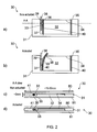
- Figure 2 shows a microvalve assembly 30 fabricated on a printed circuit board (PCB) substrate 31.
- Figure 2a shows a plan view of the substrate 31 with the valve in a non-actuated configuration.
- Figure 2b shows a plan view of the substrate 31 with the valve in an actuated configuration.
- Figures 2c and 2d each show a cross-section through the PCB substrate 31 respectively also showing the valve in a non-actuated and an actuated configuration.
- the valve assembly 30 comprises an aperture 32 in the PCB substrate. Extending into the aperture 32 is a cantilever member 33 which is preferably an integral part of the PCB substrate 31 created during formation of the aperture 32. However, the cantilever member 33 could be fabricated separately and affixed to the PCB substrate 31 so as to extend into the aperture.
- a shape memory alloy (SMA) wire 34 extends across the aperture 32 and is secured to the PCB substrate 31 at connection points 35, 36.
- the connection points can be any suitable type of mechanism for securing the wire 34 to the substrate 31 such as by soldered contacts or by the wire 34 looping around a structure embedded in or attached to the substrate.
- the wire loop could be closed by a clamp or other mechanism.
- Electrically conductive tracks 40 extend across the PCB substrate 31 to ends of the shape memory alloy wire 34, forming electrical connections thereto.
- the fluid conduit 38 is preferably a flexible pipe and can be compressed to restrict the flow of fluid through the pipe.
- the cantilever member 33 includes a nub 39 (e.g. a protuberance or boss) extending laterally outward towards the closure edge 37 of the aperture 32.
- the nub 39 provides a pinch point which locally compresses the pipe 38 to shut off fluid flow therethrough.
- the nub 39 is shown on the cantilever member 33, it could alternatively be located on the closure edge 37 of the substrate where the pinch point is required, or nubs 39 could be formed on the cantilever member 33 and the closure edge 37 of the aperture to work in opposition to one another.
- the shape memory alloy wire 34 has a negative thermal coefficient of expansion in that it contracts significantly as its temperature rises above a certain threshold. As the SMA wire 34 contracts, the cantilever member 33 is flexed away from the aperture closure edge 37 thereby relieving pressure on the pipe 38 and opening the lumen within the pipe walls. Thermal activation of the shape memory alloy wire 34 (i.e. heating and cooling of the wire) can be effected by switching on and off electrical current through the wire, the current being delivered via the electrically conductive tracks 40. When electrical current is turned off and the wire 34 cools down, the cantilever member returns to its unbiased configuration thereby closing the lumen within the pipe walls.
- the fluid conduit 38 can be fabricated from any suitable flexible, compressible tubing such as Tygon (TM) or silicone tubing.
- the flexible tubing has an outside diameter of 2 mm and is pinched between a cantilever 33 and printed circuit board closure edge 37 of thickness between 1 and 2 mm.
- the SMA wire 34 extends over a length of between 15 and 30 mm. Other dimensions are possible.
- the cantilever 33 could be replaced by a bridge member extending right across the aperture. However, increased flexibility of the material (e.g. the PCB material) forming the bridge may then be required in order to ensure sufficient lateral displacement of the bridge member to compress or decompress the adjacent pipe 38.
- the cantilever 33 and the alternative bridge member are generally examples of a closure member configured to be able to flex under the force applied by a displacement member such as SMA wire 34.
- the shape memory alloy wire 34 exemplifies a tension wire connected to and extending between a closure member such as the cantilever 33 and a main body of the PCB substrate 31, i.e. a portion of the substrate lying outside the aperture separate from any cantilever or bridge member extending into the aperture 32.
- the fluid pipe 38 can be configured to lie in the plane of the PCB substrate 31 at the pinch point defined by nub 39 or could pass through the plane of the PCB substrate 31 at the pinch point defined by nub 39, either in an orthogonal or oblique direction relative to the plane of the PCB substrate.
- the microvalve of figure 2 need not be of a normally-closed configuration.
- the cantilever 33 or other closure member and the wire 34 or other displacement member could be arranged to provide a normally-open configuration and operate to close or restrict the pipe when the displacement member is thermally actuated.
- the wire 34 can extend across the gap between the cantilever 33 and the closure edge 37 of the aperture to compress the pipe 38.
- the end of the wire 34 can extend well past the closure edge 37 before being fixed to the substrate 31.
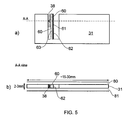
- Figure 3 illustrates a general method for ensuring sufficient length of SMA wire 34 to provide enough thermal contraction to effect full displacement of the cantilever 33. If the aperture 32 is too small to provide sufficient length of SMA wire 34 (or other displacement member), the wire 34 can be extended over not only the aperture 32 but also a length of substrate 31 to a connection point 35 somewhat remote from one edge of the aperture. In the example shown in figure 3 , a 1 mm displacement of the cantilever 33 can be effected by a 25 mm length of shape memory wire 34, actuated at a typical actuation temperature of perhaps 70 - 90 °C.
- Figure 3 also generally illustrates an example in which the fluid pipe 38 extends through the plane of the substrate 31, as discussed earlier.
- Figure 4 illustrates a modification to the arrangement of figure 3 , showing an example of how to form the microvalve as a latching valve 50.
- the microvalve 50 includes a cantilever 33 which includes a latch member 51 formed as a transverse cantilever.
- the latch member 51 is configured to engage with a tooth 52 extending outward from an edge 53 of the aperture 32.
- the latch member 51 is deflectable by way of a second shape memory alloy wire 54 in much the same way as described in connection with the shape memory alloy wire 34. More specifically, the wire 54 may be thermally actuated by passing an electrical current through it, so shortening the wire and displacing the latch member 51 to disengage from the tooth 52.
- FIG. 4 shows a normally closed valve 50 i.e. when the cantilever 33 is unbiased, which valve can be opened using thermal actuation of wire 34, and which will latch open by engagement of latch member 51 against tooth 52. The thermal actuation of wire 34 can then be discontinued.
- the second SMA wire 54 is thermally actuated causing the latch member 51 to deflect away from the aperture edge 53 and disengage from the tooth 52 so that the cantilever 33 returns to its unbiased configuration.
- the cantilever 60 may include an edge 61 which is plated with a suitable metal 62 having a thermal coefficient of expansion which is different from the thermal coefficient of expansion of the cantilever material (e.g. the PCB substrate material).
- a metallic strip or wire 63 disposed on the cantilever 60 is operable as a heating element to heat the cantilever and thereby cause differential expansion of the materials and consequently cause cantilever deflection.
- the cantilever may be operated in a similar manner to a bimetallic strip actuator according to known principles.
- the edge 61 may be plated with gold, copper or nickel.
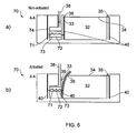
- a microvalve 70 comprises an encapsulated heater element 71 which is surrounded by a low melting temperature metal 72, such as Field's metal or Wood's metal, in a flexible capsule 73 positioned between the cantilever 33 and a bearing edge 74 of the aperture 32.
- the capsule may be formed of a suitable elastomeric polymer such as PDMS (polydimethylsiloxane).
- the heater element 71 may be a copper coil.
- the heater element 71 may be actuated by electrical current delivered by electrically conductive tracks 40.
- the heater element 71 could alternatively be outside the capsule 73. If the heater element 71 is within the capsule, it may be insulated to prevent short circuit via the low melting temperature metal.
- Figure 6a shows the latching microvalve 70 in an unbiased, unlatched configuration.
- Figure 6b shows the microvalve 70 in a latched condition.
- the low melting temperature metal 72 may be heated using the heater element 71 before (and / or contemporaneously with) heating of the SMA wire 34.
- the low melting temperature metal 72 becomes molten (at approximately 62 °C or 70 °C respectively for Field's and Wood's metals) and therefore the flexible capsule 73 is able to reshape under the tension applied by the wire 34 to the cantilever 33.
- the heater element 71 is then deactivated causing the low melting temperature metal 72 to solidify again in the elongated shape ( figure 6b ).
- the cantilever 33 remains biased away from the fluid pipe 38 even when the shape memory alloy wire 34 is deactivated.
- the low melting temperature metal is heated with heater element 71; the SMA wire is heated; the heater element 71 is deactivated while the SMA wire remains heated; the metal 72 solidifies; and the SMA wire heating is then deactivated.
- the latch member 51 and tooth 52, and the flexible capsule 73 described above generally exemplify a latching mechanism which is configurable to retain the closure member (e.g. the cantilever 33) in its displaced condition independent of the thermal actuation state of the displacement member (e.g. SMA wire 34).
- the latching mechanism will retain the cantilever 33 in its displaced or deflected position even when the thermal actuation of the displacement member is ceased or switched off.
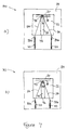
- a microvalve assembly 90 comprises an aperture 32 in the substrate 31. Extending into the aperture 32 is an axially compressible closure member 91 which extends from a proximal end 92 at an edge of the aperture 32 to a distal end 93 remote therefrom.
- the closure member 91 may be an integral part of the substrate 31 created during formation on the aperture 32 or may be attached to the substrate during manufacture.
- the axially compressible closure member 91 may be formed of any suitable compressible material such as an elastomeric material.
- the axially compressible closure member 91 could comprise a helical spring.
- a shape memory alloy (SMA) wire 34 extends from the substrate 31 at connection points 35a, 35b around a connection point 36 at or close to the distal end of the closure member 91.
- the connection points can be any suitable type of mechanism for securing the wire 34 to the substrate 31 such as by soldered contacts or by the wire looping around a structure embedded in or attached to the substrate 31.
- the wire loop could be closed by a clamp or other mechanism.
- Electrically conductive tracks 40 extend across the substrate 31 to ends of the SMA wire 34 forming electrical connections thereto.
- the fluid conduit 38 is preferably a flexible pipe and can be compressed to restrict the flow of fluid through the pipe.
- the SMA 34 may have a negative thermal coefficient of expansion in that it contracts significantly as its temperature rises, e.g. by electrical current heating.
- the closure member 91 is axially compressed so that it moves, from its non-actuated configuration ( figure 7a ) in which the fluid conduit 38 is compressed and occluded, to its actuated configuration ( figure 7b ) in which the fluid conduit 38 is not compressed and therefore not occluded.
- the fluid pipe 38 can be configured to lie in the plane of the substrate 31 passing the pinch point defined by the closure edge 37 of the aperture and the distal end 93 of the closure member.
- the fluid pipe 38 can be configured to pass through the plane of the substrate 31 at the pinch point defined by the closure edge 37 of the aperture and the distal end 93 of the closure member.
- Other features of the previously described embodiments can also be applied to the arrangement of figure 7 .
- All of the microvalves described above can be implemented substantially within the plane of the printed circuit board substrate 31, thus providing a very low profile microvalve suitable for sandwiching into the stacked plates of a fuel cell stack such as shown in figure 1 .
- the shape memory alloy wires 34, 54 and / or their connection points 35, 36 can be recessed slightly below the main or major surface 41 (see figures 2c, 2d ) of the substrate 31.
- the cantilever member 33 can be made slightly thinner or lower profile than the substrate 31 to ensure there is no binding against layers stacked onto the printed circuit board.
- the printed circuit board substrate 31 can be overlaid with, or sandwiched between cover or capping layers 80, 81 as shown in figures 2c and 2d and figure 5 .
- the microvalve can be configured such that the movement of the closure members (e.g. cantilever member 33 or a bridge member) and the movement of the displacement members (e.g. shape memory alloy wires 34, 54) occurs entirely within the plane of the PCB substrate 31 thereby requiring no moving parts to extend out of the plane of the substrate 31.
- This provides a very low profile microvalve ideally suited to the stacked plates of the fuel cell stack 1.
- actuation temperatures of the displacement members of the microvalves described can be made compatible with a normal operating temperature of a fuel cell stack.
- Typical temperatures found near the end plates 13, 14 of the fuel cell stack 1 may be of the order of 50 °C and wire actuation temperatures can be in the range of 70 - 90 °C.
- Various safety cut-out mechanisms may be integrated with the microvalve.
- one or more thermal (melt) fuses could be incorporated into the wire 34 which could melt thereby breaking the tension in the wire and forcing a valve closure.
- microvalves described above can be integrated into the printed circuit board current collector plates 9 and / or 11 thereby requiring little or no increase in dimensions of the fuel cell stack.
- the microvalve apertures 32 can be positioned in the collector plate end sections 23, 24 aligned with the ports 19, 20 so that a hydrogen fuel pipe extending therethrough can be positioned to pass through the microvalve assembly.
- microvalve as described herein can be applied to other types of fuel cell stack, such as a closed-cathode fuel cell stacks in which an oxidant pipe may also be flow controlled.
- the microvalves can also be used to control purge lines, and in particular anode purge lines.
- the normally-closed configuration of microvalve can be particularly useful to automatically isolate the hydrogen flow paths within the cells of the fuel cell stack from external ambient when the fuel cell is disconnected from a fuel source.
- any suitable material may be used for fabricating the printed circuit board used as substrate 31, including all conventional PCB materials such as cloth, textile, fibre or paper layers impregnated in resins or other thermosetting dielectric materials, suitable for printing or otherwise applying electrically conductive materials, or laminates having copper or other conductive layers already applied for suitable etching and removal where not required.
- Other substrate materials e.g. non-PCB materials
- PCB materials may be considered, however, for supporting the various elements of the valve assembly described above. These could include plastics, dielectric materials etc.
- microvalve assembly described here is particularly suited to small-scale fuel cell stacks with few cells, such as those that can be used in consumer electronic devices. However, the principle can be applied to larger fuel cell stacks. Further, the microvalves described here can be generally used in many types of device other than fuel cells.
- the displacement member could include multiple tension wires 34 to increase the possible tension applied to the closure member (e.g. cantilever 33).
- the wires could stretch back and forth between the main body of the PCB substrate and the cantilever.
- the microvalve described can be configured to operate not only between fully open and fully closed fluid pipe configurations, but may also operate with partially open configurations. This could be achieved by enabling reduced heating of the SMA wires, for partial contraction. In this way, the microvalve may be configured to operate as a variable pressure regulator. Such a functionality could be implemented not only with analogue control of the thermal actuation of the displacement member, but alternatively by digital control of the thermal actuation, to implement a pulse-width modulation of the open-closed configurations.
Applications Claiming Priority (2)
| Application Number | Priority Date | Filing Date | Title |
|---|---|---|---|
| GB201221885 | 2012-12-05 | ||
| PCT/GB2013/053206 WO2014087160A1 (en) | 2012-12-05 | 2013-12-04 | Microvalve |
Publications (2)
| Publication Number | Publication Date |
|---|---|
| EP2929223A1 EP2929223A1 (en) | 2015-10-14 |
| EP2929223B1 true EP2929223B1 (en) | 2016-11-23 |
Family
ID=49917663
Family Applications (1)
| Application Number | Title | Priority Date | Filing Date |
|---|---|---|---|
| EP13817711.8A Not-in-force EP2929223B1 (en) | 2012-12-05 | 2013-12-04 | Microvalve |
Country Status (8)
| Country | Link |
|---|---|
| US (1) | US10290879B2 (ko) |
| EP (1) | EP2929223B1 (ko) |
| JP (1) | JP6541574B2 (ko) |
| KR (1) | KR20150090255A (ko) |
| CN (1) | CN104937320B (ko) |
| SG (1) | SG11201504406RA (ko) |
| TW (1) | TWI635234B (ko) |
| WO (1) | WO2014087160A1 (ko) |
Families Citing this family (13)
| Publication number | Priority date | Publication date | Assignee | Title |
|---|---|---|---|---|
| US9627722B1 (en) | 2013-09-16 | 2017-04-18 | American Lithium Energy Corporation | Positive temperature coefficient film, positive temperature coefficient electrode, positive temperature coefficient separator, and battery comprising the same |
| US10020545B2 (en) | 2014-11-25 | 2018-07-10 | American Lithium Energy Corporation | Rechargeable battery with resistive layer for enhanced safety |
| HUE049590T2 (hu) | 2014-11-25 | 2020-09-28 | American Lithium Energy Corp | Újratölthetõ akkumulátor belsõ áramhatárolóval és árammegszakítóval |
| WO2016141033A1 (en) * | 2015-03-02 | 2016-09-09 | Board Of Regents, The University Of Texas System | Systems and methods for thermally actuated flow control |
| CN105304409A (zh) * | 2015-09-11 | 2016-02-03 | 中国科学院理化技术研究所 | 一种基于负热膨胀的热开关 |
| FR3045012B1 (fr) * | 2015-12-11 | 2017-12-08 | Airbus Operations Sas | Mat d'accrochage d'une turbomachine muni d'un element de protection thermique |
| DE102016219342A1 (de) | 2016-10-06 | 2018-04-12 | Conti Temic Microelectronic Gmbh | Pneumatisches Ventil |
| CN106410239A (zh) * | 2016-11-02 | 2017-02-15 | 上海钧希新能源科技有限公司 | 一种模块化甲醇水储液容器 |
| EP3619761B1 (en) * | 2017-05-01 | 2021-03-03 | American Lithium Energy Corporation | Negative thermal expansion current interrupter |
| CN108167469A (zh) * | 2018-01-31 | 2018-06-15 | 兰州大学 | 一种钨酸锆负热膨胀材料智能阀门 |
| JP7075780B2 (ja) * | 2018-02-28 | 2022-05-26 | 本田技研工業株式会社 | 燃料電池システム |
| DE102018216876B4 (de) | 2018-10-01 | 2022-10-27 | Conti Temic Microelectronic Gmbh | Pneumatisches Ventil |
| US11015736B1 (en) * | 2019-01-24 | 2021-05-25 | Vector Ring LLC | Clamp utilizing a shape memory alloy actuator to shutoff, squeeze off, plastic pipe and tubing used in the pressurized transmission of gas or fluid |
Family Cites Families (16)
| Publication number | Priority date | Publication date | Assignee | Title |
|---|---|---|---|---|
| JPH0211980A (ja) * | 1988-06-28 | 1990-01-17 | Matsushita Refrig Co Ltd | ダンパー開閉装置 |
| JPH04136571A (ja) | 1990-09-25 | 1992-05-11 | Shibaura Eng Works Co Ltd | チューブラバルブ |
| JPH06111838A (ja) * | 1992-09-30 | 1994-04-22 | Toshiba Corp | 改質器、改質システム、及び燃料電池システム |
| JPH11324902A (ja) * | 1998-05-06 | 1999-11-26 | Kitz Corp | 電熱式アクチュエータ、バルブ及びポンプ |
| CN1081294C (zh) * | 1999-08-04 | 2002-03-20 | 上海交通大学 | 采用形状记忆合金/硅双层驱动膜结构的微泵 |
| US6211598B1 (en) | 1999-09-13 | 2001-04-03 | Jds Uniphase Inc. | In-plane MEMS thermal actuator and associated fabrication methods |
| US6494804B1 (en) * | 2000-06-20 | 2002-12-17 | Kelsey-Hayes Company | Microvalve for electronically controlled transmission |
| EP1331997B1 (en) * | 2000-11-06 | 2004-06-16 | Nanostream, Inc. | Microfluidic flow control devices |
| US7686040B2 (en) | 2004-06-24 | 2010-03-30 | The Aerospace Corporation | Electro-hydraulic devices |
| CN101002029A (zh) * | 2004-07-23 | 2007-07-18 | 阿法控制装置有限责任公司 | 微阀组件及相关方法 |
| US20060122565A1 (en) | 2004-11-23 | 2006-06-08 | Kooi Chee C | Switch structures or the like based on a thermoresponsive polymer |
| KR100966945B1 (ko) | 2005-07-26 | 2010-06-30 | 파나소닉 전공 주식회사 | 소형밸브 |
| US8679694B2 (en) | 2007-03-21 | 2014-03-25 | Societe Bic | Fluidic control system and method of manufacture |
| US20100093559A1 (en) * | 2007-03-28 | 2010-04-15 | Zhonghui Fan | Microfluidic Array Device and System for Simultaneous Detection of Multiple Analytes |
| CN102003560B (zh) * | 2010-10-14 | 2012-02-08 | 清华大学 | 一种电驱动形状记忆合金丝的常闭型主动微阀 |
| GB201103590D0 (en) * | 2011-03-01 | 2011-04-13 | Imp Innovations Ltd | Fuel cell |
-
2013
- 2013-12-04 US US14/649,397 patent/US10290879B2/en not_active Expired - Fee Related
- 2013-12-04 KR KR1020157017878A patent/KR20150090255A/ko not_active Application Discontinuation
- 2013-12-04 CN CN201380063573.2A patent/CN104937320B/zh not_active Expired - Fee Related
- 2013-12-04 EP EP13817711.8A patent/EP2929223B1/en not_active Not-in-force
- 2013-12-04 SG SG11201504406RA patent/SG11201504406RA/en unknown
- 2013-12-04 JP JP2015546093A patent/JP6541574B2/ja active Active
- 2013-12-04 WO PCT/GB2013/053206 patent/WO2014087160A1/en active Application Filing
- 2013-12-05 TW TW102144520A patent/TWI635234B/zh not_active IP Right Cessation
Non-Patent Citations (1)
| Title |
|---|
| None * |
Also Published As
| Publication number | Publication date |
|---|---|
| WO2014087160A1 (en) | 2014-06-12 |
| JP2016501348A (ja) | 2016-01-18 |
| SG11201504406RA (en) | 2015-07-30 |
| JP6541574B2 (ja) | 2019-07-10 |
| US10290879B2 (en) | 2019-05-14 |
| TWI635234B (zh) | 2018-09-11 |
| CN104937320A (zh) | 2015-09-23 |
| CN104937320B (zh) | 2019-05-07 |
| EP2929223A1 (en) | 2015-10-14 |
| TW201435234A (zh) | 2014-09-16 |
| KR20150090255A (ko) | 2015-08-05 |
| US20160064750A1 (en) | 2016-03-03 |
Similar Documents
| Publication | Publication Date | Title |
|---|---|---|
| EP2929223B1 (en) | Microvalve | |
| CN107061785B (zh) | 形状记忆合金致动阀门组合件及用于其的阀门子组合件 | |
| EP1620349B1 (en) | Mems actuators | |
| US5325880A (en) | Shape memory alloy film actuated microvalve | |
| JP6117106B2 (ja) | 保護装置 | |
| EP0469749A1 (en) | Control valve utilizing mechanical beam buckling | |
| US8480057B2 (en) | Microvalve and valve seat member | |
| WO2005076301A1 (ja) | スイッチおよびこれを用いた装置 | |
| WO2010049092A1 (de) | Mikroventil in keramischer mehrlagentechnik sowie dessen verwendung | |
| US8362375B2 (en) | Pressure differential switch | |
| CN106449965A (zh) | 薄片转换器及用于薄片转换器的致动器条 | |
| TWI313883B (en) | Relay device using conductive fluid | |
| US11004621B2 (en) | Relay | |
| JP4880167B2 (ja) | マイクロアクチュエータ装置 | |
| US11136968B2 (en) | Actuator assembly | |
| WO2008081911A1 (ja) | 燃料電池用断熱セルおよびその製造方法 | |
| WO2008113166A1 (en) | Mems actuators and switches | |
| JPH01105430A (ja) | 自己保持型保護スイッチ | |
| US20230335358A1 (en) | Electric circuit |
Legal Events
| Date | Code | Title | Description |
|---|---|---|---|
| PUAI | Public reference made under article 153(3) epc to a published international application that has entered the european phase |
Free format text: ORIGINAL CODE: 0009012 |
|
| 17P | Request for examination filed |
Effective date: 20150605 |
|
| AK | Designated contracting states |
Kind code of ref document: A1 Designated state(s): AL AT BE BG CH CY CZ DE DK EE ES FI FR GB GR HR HU IE IS IT LI LT LU LV MC MK MT NL NO PL PT RO RS SE SI SK SM TR |
|
| AX | Request for extension of the european patent |
Extension state: BA ME |
|
| DAX | Request for extension of the european patent (deleted) | ||
| GRAP | Despatch of communication of intention to grant a patent |
Free format text: ORIGINAL CODE: EPIDOSNIGR1 |
|
| INTG | Intention to grant announced |
Effective date: 20160530 |
|
| GRAS | Grant fee paid |
Free format text: ORIGINAL CODE: EPIDOSNIGR3 |
|
| GRAJ | Information related to disapproval of communication of intention to grant by the applicant or resumption of examination proceedings by the epo deleted |
Free format text: ORIGINAL CODE: EPIDOSDIGR1 |
|
| GRAL | Information related to payment of fee for publishing/printing deleted |
Free format text: ORIGINAL CODE: EPIDOSDIGR3 |
|
| GRAR | Information related to intention to grant a patent recorded |
Free format text: ORIGINAL CODE: EPIDOSNIGR71 |
|
| GRAA | (expected) grant |
Free format text: ORIGINAL CODE: 0009210 |
|
| INTC | Intention to grant announced (deleted) | ||
| INTG | Intention to grant announced |
Effective date: 20161011 |
|
| AK | Designated contracting states |
Kind code of ref document: B1 Designated state(s): AL AT BE BG CH CY CZ DE DK EE ES FI FR GB GR HR HU IE IS IT LI LT LU LV MC MK MT NL NO PL PT RO RS SE SI SK SM TR |
|
| REG | Reference to a national code |
Ref country code: GB Ref legal event code: FG4D |
|
| REG | Reference to a national code |
Ref country code: CH Ref legal event code: EP |
|
| REG | Reference to a national code |
Ref country code: FR Ref legal event code: PLFP Year of fee payment: 4 |
|
| REG | Reference to a national code |
Ref country code: IE Ref legal event code: FG4D |
|
| REG | Reference to a national code |
Ref country code: AT Ref legal event code: REF Ref document number: 848226 Country of ref document: AT Kind code of ref document: T Effective date: 20161215 |
|
| REG | Reference to a national code |
Ref country code: DE Ref legal event code: R096 Ref document number: 602013014545 Country of ref document: DE |
|
| PG25 | Lapsed in a contracting state [announced via postgrant information from national office to epo] |
Ref country code: LV Free format text: LAPSE BECAUSE OF FAILURE TO SUBMIT A TRANSLATION OF THE DESCRIPTION OR TO PAY THE FEE WITHIN THE PRESCRIBED TIME-LIMIT Effective date: 20161123 |
|
| REG | Reference to a national code |
Ref country code: LT Ref legal event code: MG4D |
|
| REG | Reference to a national code |
Ref country code: NL Ref legal event code: MP Effective date: 20161123 |
|
| REG | Reference to a national code |
Ref country code: AT Ref legal event code: MK05 Ref document number: 848226 Country of ref document: AT Kind code of ref document: T Effective date: 20161123 |
|
| PG25 | Lapsed in a contracting state [announced via postgrant information from national office to epo] |
Ref country code: GR Free format text: LAPSE BECAUSE OF FAILURE TO SUBMIT A TRANSLATION OF THE DESCRIPTION OR TO PAY THE FEE WITHIN THE PRESCRIBED TIME-LIMIT Effective date: 20170224 Ref country code: NO Free format text: LAPSE BECAUSE OF FAILURE TO SUBMIT A TRANSLATION OF THE DESCRIPTION OR TO PAY THE FEE WITHIN THE PRESCRIBED TIME-LIMIT Effective date: 20170223 Ref country code: LT Free format text: LAPSE BECAUSE OF FAILURE TO SUBMIT A TRANSLATION OF THE DESCRIPTION OR TO PAY THE FEE WITHIN THE PRESCRIBED TIME-LIMIT Effective date: 20161123 Ref country code: SE Free format text: LAPSE BECAUSE OF FAILURE TO SUBMIT A TRANSLATION OF THE DESCRIPTION OR TO PAY THE FEE WITHIN THE PRESCRIBED TIME-LIMIT Effective date: 20161123 Ref country code: NL Free format text: LAPSE BECAUSE OF FAILURE TO SUBMIT A TRANSLATION OF THE DESCRIPTION OR TO PAY THE FEE WITHIN THE PRESCRIBED TIME-LIMIT Effective date: 20161123 |
|
| PG25 | Lapsed in a contracting state [announced via postgrant information from national office to epo] |
Ref country code: ES Free format text: LAPSE BECAUSE OF FAILURE TO SUBMIT A TRANSLATION OF THE DESCRIPTION OR TO PAY THE FEE WITHIN THE PRESCRIBED TIME-LIMIT Effective date: 20161123 Ref country code: FI Free format text: LAPSE BECAUSE OF FAILURE TO SUBMIT A TRANSLATION OF THE DESCRIPTION OR TO PAY THE FEE WITHIN THE PRESCRIBED TIME-LIMIT Effective date: 20161123 Ref country code: PT Free format text: LAPSE BECAUSE OF FAILURE TO SUBMIT A TRANSLATION OF THE DESCRIPTION OR TO PAY THE FEE WITHIN THE PRESCRIBED TIME-LIMIT Effective date: 20170323 Ref country code: RS Free format text: LAPSE BECAUSE OF FAILURE TO SUBMIT A TRANSLATION OF THE DESCRIPTION OR TO PAY THE FEE WITHIN THE PRESCRIBED TIME-LIMIT Effective date: 20161123 Ref country code: BE Free format text: LAPSE BECAUSE OF NON-PAYMENT OF DUE FEES Effective date: 20161231 Ref country code: AT Free format text: LAPSE BECAUSE OF FAILURE TO SUBMIT A TRANSLATION OF THE DESCRIPTION OR TO PAY THE FEE WITHIN THE PRESCRIBED TIME-LIMIT Effective date: 20161123 Ref country code: HR Free format text: LAPSE BECAUSE OF FAILURE TO SUBMIT A TRANSLATION OF THE DESCRIPTION OR TO PAY THE FEE WITHIN THE PRESCRIBED TIME-LIMIT Effective date: 20161123 Ref country code: PL Free format text: LAPSE BECAUSE OF FAILURE TO SUBMIT A TRANSLATION OF THE DESCRIPTION OR TO PAY THE FEE WITHIN THE PRESCRIBED TIME-LIMIT Effective date: 20161123 |
|
| PG25 | Lapsed in a contracting state [announced via postgrant information from national office to epo] |
Ref country code: SK Free format text: LAPSE BECAUSE OF FAILURE TO SUBMIT A TRANSLATION OF THE DESCRIPTION OR TO PAY THE FEE WITHIN THE PRESCRIBED TIME-LIMIT Effective date: 20161123 Ref country code: CZ Free format text: LAPSE BECAUSE OF FAILURE TO SUBMIT A TRANSLATION OF THE DESCRIPTION OR TO PAY THE FEE WITHIN THE PRESCRIBED TIME-LIMIT Effective date: 20161123 Ref country code: EE Free format text: LAPSE BECAUSE OF FAILURE TO SUBMIT A TRANSLATION OF THE DESCRIPTION OR TO PAY THE FEE WITHIN THE PRESCRIBED TIME-LIMIT Effective date: 20161123 Ref country code: RO Free format text: LAPSE BECAUSE OF FAILURE TO SUBMIT A TRANSLATION OF THE DESCRIPTION OR TO PAY THE FEE WITHIN THE PRESCRIBED TIME-LIMIT Effective date: 20161123 Ref country code: DK Free format text: LAPSE BECAUSE OF FAILURE TO SUBMIT A TRANSLATION OF THE DESCRIPTION OR TO PAY THE FEE WITHIN THE PRESCRIBED TIME-LIMIT Effective date: 20161123 |
|
| REG | Reference to a national code |
Ref country code: CH Ref legal event code: PL |
|
| REG | Reference to a national code |
Ref country code: DE Ref legal event code: R097 Ref document number: 602013014545 Country of ref document: DE |
|
| PG25 | Lapsed in a contracting state [announced via postgrant information from national office to epo] |
Ref country code: BG Free format text: LAPSE BECAUSE OF FAILURE TO SUBMIT A TRANSLATION OF THE DESCRIPTION OR TO PAY THE FEE WITHIN THE PRESCRIBED TIME-LIMIT Effective date: 20170223 Ref country code: BE Free format text: LAPSE BECAUSE OF FAILURE TO SUBMIT A TRANSLATION OF THE DESCRIPTION OR TO PAY THE FEE WITHIN THE PRESCRIBED TIME-LIMIT Effective date: 20161123 Ref country code: IT Free format text: LAPSE BECAUSE OF FAILURE TO SUBMIT A TRANSLATION OF THE DESCRIPTION OR TO PAY THE FEE WITHIN THE PRESCRIBED TIME-LIMIT Effective date: 20161123 Ref country code: SM Free format text: LAPSE BECAUSE OF FAILURE TO SUBMIT A TRANSLATION OF THE DESCRIPTION OR TO PAY THE FEE WITHIN THE PRESCRIBED TIME-LIMIT Effective date: 20161123 |
|
| PG25 | Lapsed in a contracting state [announced via postgrant information from national office to epo] |
Ref country code: MC Free format text: LAPSE BECAUSE OF FAILURE TO SUBMIT A TRANSLATION OF THE DESCRIPTION OR TO PAY THE FEE WITHIN THE PRESCRIBED TIME-LIMIT Effective date: 20161123 |
|
| PLBE | No opposition filed within time limit |
Free format text: ORIGINAL CODE: 0009261 |
|
| STAA | Information on the status of an ep patent application or granted ep patent |
Free format text: STATUS: NO OPPOSITION FILED WITHIN TIME LIMIT |
|
| REG | Reference to a national code |
Ref country code: IE Ref legal event code: MM4A |
|
| PG25 | Lapsed in a contracting state [announced via postgrant information from national office to epo] |
Ref country code: LI Free format text: LAPSE BECAUSE OF NON-PAYMENT OF DUE FEES Effective date: 20161231 Ref country code: LU Free format text: LAPSE BECAUSE OF NON-PAYMENT OF DUE FEES Effective date: 20161204 Ref country code: CH Free format text: LAPSE BECAUSE OF NON-PAYMENT OF DUE FEES Effective date: 20161231 |
|
| 26N | No opposition filed |
Effective date: 20170824 |
|
| PG25 | Lapsed in a contracting state [announced via postgrant information from national office to epo] |
Ref country code: IE Free format text: LAPSE BECAUSE OF NON-PAYMENT OF DUE FEES Effective date: 20161204 Ref country code: SI Free format text: LAPSE BECAUSE OF FAILURE TO SUBMIT A TRANSLATION OF THE DESCRIPTION OR TO PAY THE FEE WITHIN THE PRESCRIBED TIME-LIMIT Effective date: 20161123 |
|
| REG | Reference to a national code |
Ref country code: FR Ref legal event code: PLFP Year of fee payment: 5 |
|
| PG25 | Lapsed in a contracting state [announced via postgrant information from national office to epo] |
Ref country code: HU Free format text: LAPSE BECAUSE OF FAILURE TO SUBMIT A TRANSLATION OF THE DESCRIPTION OR TO PAY THE FEE WITHIN THE PRESCRIBED TIME-LIMIT; INVALID AB INITIO Effective date: 20131204 |
|
| PG25 | Lapsed in a contracting state [announced via postgrant information from national office to epo] |
Ref country code: CY Free format text: LAPSE BECAUSE OF FAILURE TO SUBMIT A TRANSLATION OF THE DESCRIPTION OR TO PAY THE FEE WITHIN THE PRESCRIBED TIME-LIMIT Effective date: 20161123 Ref country code: MK Free format text: LAPSE BECAUSE OF FAILURE TO SUBMIT A TRANSLATION OF THE DESCRIPTION OR TO PAY THE FEE WITHIN THE PRESCRIBED TIME-LIMIT Effective date: 20161123 Ref country code: IS Free format text: LAPSE BECAUSE OF FAILURE TO SUBMIT A TRANSLATION OF THE DESCRIPTION OR TO PAY THE FEE WITHIN THE PRESCRIBED TIME-LIMIT Effective date: 20161123 |
|
| REG | Reference to a national code |
Ref country code: DE Ref legal event code: R082 Ref document number: 602013014545 Country of ref document: DE Representative=s name: FLACH BAUER & PARTNER PATENTANWAELTE MBB, DE Ref country code: DE Ref legal event code: R082 Ref document number: 602013014545 Country of ref document: DE Representative=s name: FLACH BAUER STAHL PATENTANWAELTE PARTNERSCHAFT, DE |
|
| PG25 | Lapsed in a contracting state [announced via postgrant information from national office to epo] |
Ref country code: MT Free format text: LAPSE BECAUSE OF NON-PAYMENT OF DUE FEES Effective date: 20161204 |
|
| PG25 | Lapsed in a contracting state [announced via postgrant information from national office to epo] |
Ref country code: TR Free format text: LAPSE BECAUSE OF FAILURE TO SUBMIT A TRANSLATION OF THE DESCRIPTION OR TO PAY THE FEE WITHIN THE PRESCRIBED TIME-LIMIT Effective date: 20161123 |
|
| PG25 | Lapsed in a contracting state [announced via postgrant information from national office to epo] |
Ref country code: AL Free format text: LAPSE BECAUSE OF FAILURE TO SUBMIT A TRANSLATION OF THE DESCRIPTION OR TO PAY THE FEE WITHIN THE PRESCRIBED TIME-LIMIT Effective date: 20161123 |
|
| PGFP | Annual fee paid to national office [announced via postgrant information from national office to epo] |
Ref country code: DE Payment date: 20211227 Year of fee payment: 9 Ref country code: FR Payment date: 20211227 Year of fee payment: 9 Ref country code: GB Payment date: 20211227 Year of fee payment: 9 |
|
| REG | Reference to a national code |
Ref country code: DE Ref legal event code: R119 Ref document number: 602013014545 Country of ref document: DE |
|
| GBPC | Gb: european patent ceased through non-payment of renewal fee |
Effective date: 20221204 |
|
| PG25 | Lapsed in a contracting state [announced via postgrant information from national office to epo] |
Ref country code: GB Free format text: LAPSE BECAUSE OF NON-PAYMENT OF DUE FEES Effective date: 20221204 Ref country code: DE Free format text: LAPSE BECAUSE OF NON-PAYMENT OF DUE FEES Effective date: 20230701 |
|
| PG25 | Lapsed in a contracting state [announced via postgrant information from national office to epo] |
Ref country code: FR Free format text: LAPSE BECAUSE OF NON-PAYMENT OF DUE FEES Effective date: 20221231 |