EP2928792B1 - Réceptacle à partie amovible - Google Patents
Réceptacle à partie amovible Download PDFInfo
- Publication number
- EP2928792B1 EP2928792B1 EP13860496.2A EP13860496A EP2928792B1 EP 2928792 B1 EP2928792 B1 EP 2928792B1 EP 13860496 A EP13860496 A EP 13860496A EP 2928792 B1 EP2928792 B1 EP 2928792B1
- Authority
- EP
- European Patent Office
- Prior art keywords
- container
- filter
- bond
- cover
- ingredients
- Prior art date
- Legal status (The legal status is an assumption and is not a legal conclusion. Google has not performed a legal analysis and makes no representation as to the accuracy of the status listed.)
- Active
Links
- 239000000463 material Substances 0.000 claims description 152
- 239000004615 ingredient Substances 0.000 claims description 64
- 238000007789 sealing Methods 0.000 claims description 37
- 238000000926 separation method Methods 0.000 claims description 32
- 230000004888 barrier function Effects 0.000 claims description 27
- 239000002775 capsule Substances 0.000 claims description 25
- 235000013361 beverage Nutrition 0.000 claims description 17
- 238000001914 filtration Methods 0.000 claims description 11
- 235000016213 coffee Nutrition 0.000 claims description 7
- 235000013353 coffee beverage Nutrition 0.000 claims description 7
- 238000000605 extraction Methods 0.000 claims description 6
- 229920000642 polymer Polymers 0.000 claims description 5
- 239000010410 layer Substances 0.000 description 61
- 239000004698 Polyethylene Substances 0.000 description 25
- 229920000573 polyethylene Polymers 0.000 description 25
- 238000000034 method Methods 0.000 description 21
- VGGSQFUCUMXWEO-UHFFFAOYSA-N Ethene Chemical compound C=C VGGSQFUCUMXWEO-UHFFFAOYSA-N 0.000 description 16
- 239000005038 ethylene vinyl acetate Substances 0.000 description 16
- 229920001684 low density polyethylene Polymers 0.000 description 16
- 239000004702 low-density polyethylene Substances 0.000 description 16
- DQXBYHZEEUGOBF-UHFFFAOYSA-N but-3-enoic acid;ethene Chemical compound C=C.OC(=O)CC=C DQXBYHZEEUGOBF-UHFFFAOYSA-N 0.000 description 14
- 229920000092 linear low density polyethylene Polymers 0.000 description 14
- 239000004707 linear low-density polyethylene Substances 0.000 description 14
- 229920001200 poly(ethylene-vinyl acetate) Polymers 0.000 description 14
- 229920001903 high density polyethylene Polymers 0.000 description 10
- 239000004700 high-density polyethylene Substances 0.000 description 10
- 239000004743 Polypropylene Substances 0.000 description 9
- QVGXLLKOCUKJST-UHFFFAOYSA-N atomic oxygen Chemical compound [O] QVGXLLKOCUKJST-UHFFFAOYSA-N 0.000 description 9
- 230000007613 environmental effect Effects 0.000 description 9
- 239000001301 oxygen Substances 0.000 description 9
- 229910052760 oxygen Inorganic materials 0.000 description 9
- -1 polyethylene Polymers 0.000 description 8
- 229920000728 polyester Polymers 0.000 description 7
- 239000005020 polyethylene terephthalate Substances 0.000 description 7
- 229920000139 polyethylene terephthalate Polymers 0.000 description 7
- 239000004716 Ethylene/acrylic acid copolymer Substances 0.000 description 6
- 239000004793 Polystyrene Substances 0.000 description 6
- 229920006226 ethylene-acrylic acid Polymers 0.000 description 6
- 238000004519 manufacturing process Methods 0.000 description 5
- 229920000098 polyolefin Polymers 0.000 description 5
- 238000003856 thermoforming Methods 0.000 description 5
- 239000000835 fiber Substances 0.000 description 4
- 238000004064 recycling Methods 0.000 description 4
- 239000004952 Polyamide Substances 0.000 description 3
- 239000004715 ethylene vinyl alcohol Substances 0.000 description 3
- 238000002347 injection Methods 0.000 description 3
- 239000007924 injection Substances 0.000 description 3
- 239000004922 lacquer Substances 0.000 description 3
- 238000004806 packaging method and process Methods 0.000 description 3
- 229920003023 plastic Polymers 0.000 description 3
- 239000004033 plastic Substances 0.000 description 3
- 229920002647 polyamide Polymers 0.000 description 3
- IJGRMHOSHXDMSA-UHFFFAOYSA-N Atomic nitrogen Chemical compound N#N IJGRMHOSHXDMSA-UHFFFAOYSA-N 0.000 description 2
- 229920003313 Bynel® Polymers 0.000 description 2
- 241001122767 Theaceae Species 0.000 description 2
- 239000000853 adhesive Substances 0.000 description 2
- 230000001070 adhesive effect Effects 0.000 description 2
- XAGFODPZIPBFFR-UHFFFAOYSA-N aluminium Chemical compound [Al] XAGFODPZIPBFFR-UHFFFAOYSA-N 0.000 description 2
- 229910052782 aluminium Inorganic materials 0.000 description 2
- 230000015572 biosynthetic process Effects 0.000 description 2
- QHZOMAXECYYXGP-UHFFFAOYSA-N ethene;prop-2-enoic acid Chemical class C=C.OC(=O)C=C QHZOMAXECYYXGP-UHFFFAOYSA-N 0.000 description 2
- 238000011049 filling Methods 0.000 description 2
- 239000012530 fluid Substances 0.000 description 2
- 239000011888 foil Substances 0.000 description 2
- 235000013305 food Nutrition 0.000 description 2
- 238000007373 indentation Methods 0.000 description 2
- 230000002093 peripheral effect Effects 0.000 description 2
- 229920002223 polystyrene Polymers 0.000 description 2
- 239000000243 solution Substances 0.000 description 2
- 235000013616 tea Nutrition 0.000 description 2
- 229920000219 Ethylene vinyl alcohol Polymers 0.000 description 1
- 229920003182 Surlyn® Polymers 0.000 description 1
- 238000000576 coating method Methods 0.000 description 1
- 230000001010 compromised effect Effects 0.000 description 1
- 238000001816 cooling Methods 0.000 description 1
- 238000005520 cutting process Methods 0.000 description 1
- 230000001419 dependent effect Effects 0.000 description 1
- YSXLJTGZMRNQSG-UHFFFAOYSA-L disodium;6-amino-5-[[2-[4-[2-[4-[2-[(2-amino-5-sulfonatonaphthalen-1-yl)diazenyl]phenyl]sulfonyloxyphenyl]propan-2-yl]phenoxy]sulfonylphenyl]diazenyl]naphthalene-1-sulfonate Chemical compound [Na+].[Na+].C1=CC=C2C(N=NC3=CC=CC=C3S(=O)(=O)OC3=CC=C(C=C3)C(C)(C=3C=CC(OS(=O)(=O)C=4C(=CC=CC=4)N=NC=4C5=CC=CC(=C5C=CC=4N)S([O-])(=O)=O)=CC=3)C)=C(N)C=CC2=C1S([O-])(=O)=O YSXLJTGZMRNQSG-UHFFFAOYSA-L 0.000 description 1
- 235000015114 espresso Nutrition 0.000 description 1
- 238000001125 extrusion Methods 0.000 description 1
- 238000007765 extrusion coating Methods 0.000 description 1
- RZXDTJIXPSCHCI-UHFFFAOYSA-N hexa-1,5-diene-2,5-diol Chemical compound OC(=C)CCC(O)=C RZXDTJIXPSCHCI-UHFFFAOYSA-N 0.000 description 1
- 235000020278 hot chocolate Nutrition 0.000 description 1
- 230000003116 impacting effect Effects 0.000 description 1
- 239000011261 inert gas Substances 0.000 description 1
- 235000021539 instant coffee Nutrition 0.000 description 1
- 238000003475 lamination Methods 0.000 description 1
- 239000011140 metalized polyester Substances 0.000 description 1
- 239000008267 milk Substances 0.000 description 1
- 210000004080 milk Anatomy 0.000 description 1
- 235000013336 milk Nutrition 0.000 description 1
- 238000009448 modified atmosphere packaging Methods 0.000 description 1
- 229910052757 nitrogen Inorganic materials 0.000 description 1
- 238000012856 packing Methods 0.000 description 1
- 229920006149 polyester-amide block copolymer Polymers 0.000 description 1
- 229920001155 polypropylene Polymers 0.000 description 1
- 239000011148 porous material Substances 0.000 description 1
- 239000000843 powder Substances 0.000 description 1
- 239000002243 precursor Substances 0.000 description 1
- 239000003755 preservative agent Substances 0.000 description 1
- 239000002356 single layer Substances 0.000 description 1
- 238000003860 storage Methods 0.000 description 1
- 229920002994 synthetic fiber Polymers 0.000 description 1
- 210000003813 thumb Anatomy 0.000 description 1
Images


Classifications
-
- B—PERFORMING OPERATIONS; TRANSPORTING
- B65—CONVEYING; PACKING; STORING; HANDLING THIN OR FILAMENTARY MATERIAL
- B65D—CONTAINERS FOR STORAGE OR TRANSPORT OF ARTICLES OR MATERIALS, e.g. BAGS, BARRELS, BOTTLES, BOXES, CANS, CARTONS, CRATES, DRUMS, JARS, TANKS, HOPPERS, FORWARDING CONTAINERS; ACCESSORIES, CLOSURES, OR FITTINGS THEREFOR; PACKAGING ELEMENTS; PACKAGES
- B65D85/00—Containers, packaging elements or packages, specially adapted for particular articles or materials
- B65D85/70—Containers, packaging elements or packages, specially adapted for particular articles or materials for materials not otherwise provided for
- B65D85/804—Disposable containers or packages with contents which are mixed, infused or dissolved in situ, i.e. without having been previously removed from the package
- B65D85/8043—Packages adapted to allow liquid to pass through the contents
- B65D85/8046—Pods, i.e. closed containers made only of filter paper or similar material
-
- B—PERFORMING OPERATIONS; TRANSPORTING
- B65—CONVEYING; PACKING; STORING; HANDLING THIN OR FILAMENTARY MATERIAL
- B65D—CONTAINERS FOR STORAGE OR TRANSPORT OF ARTICLES OR MATERIALS, e.g. BAGS, BARRELS, BOTTLES, BOXES, CANS, CARTONS, CRATES, DRUMS, JARS, TANKS, HOPPERS, FORWARDING CONTAINERS; ACCESSORIES, CLOSURES, OR FITTINGS THEREFOR; PACKAGING ELEMENTS; PACKAGES
- B65D85/00—Containers, packaging elements or packages, specially adapted for particular articles or materials
- B65D85/70—Containers, packaging elements or packages, specially adapted for particular articles or materials for materials not otherwise provided for
- B65D85/804—Disposable containers or packages with contents which are mixed, infused or dissolved in situ, i.e. without having been previously removed from the package
- B65D85/8043—Packages adapted to allow liquid to pass through the contents
- B65D85/8061—Filters
-
- B—PERFORMING OPERATIONS; TRANSPORTING
- B65—CONVEYING; PACKING; STORING; HANDLING THIN OR FILAMENTARY MATERIAL
- B65D—CONTAINERS FOR STORAGE OR TRANSPORT OF ARTICLES OR MATERIALS, e.g. BAGS, BARRELS, BOTTLES, BOXES, CANS, CARTONS, CRATES, DRUMS, JARS, TANKS, HOPPERS, FORWARDING CONTAINERS; ACCESSORIES, CLOSURES, OR FITTINGS THEREFOR; PACKAGING ELEMENTS; PACKAGES
- B65D85/00—Containers, packaging elements or packages, specially adapted for particular articles or materials
- B65D85/70—Containers, packaging elements or packages, specially adapted for particular articles or materials for materials not otherwise provided for
- B65D85/804—Disposable containers or packages with contents which are mixed, infused or dissolved in situ, i.e. without having been previously removed from the package
- B65D85/816—Disposable containers or packages with contents which are mixed, infused or dissolved in situ, i.e. without having been previously removed from the package into which liquid is added and the resulting preparation is retained, e.g. cups preloaded with powder or dehydrated food
-
- B—PERFORMING OPERATIONS; TRANSPORTING
- B65—CONVEYING; PACKING; STORING; HANDLING THIN OR FILAMENTARY MATERIAL
- B65D—CONTAINERS FOR STORAGE OR TRANSPORT OF ARTICLES OR MATERIALS, e.g. BAGS, BARRELS, BOTTLES, BOXES, CANS, CARTONS, CRATES, DRUMS, JARS, TANKS, HOPPERS, FORWARDING CONTAINERS; ACCESSORIES, CLOSURES, OR FITTINGS THEREFOR; PACKAGING ELEMENTS; PACKAGES
- B65D2565/00—Wrappers or flexible covers; Packaging materials of special type or form
- B65D2565/38—Packaging materials of special type or form
- B65D2565/381—Details of packaging materials of special type or form
- B65D2565/385—Details of packaging materials of special type or form especially suited for or with means facilitating recycling
Definitions
- This specification relates to containers and in particular to a container, such as a single serve capsule, having a portion that is removable from the remainder of the container.
- Single serve capsules for use in machines for preparing beverages or other products are becoming increasingly popular.
- Such capsules come in a variety of formats for producing products such as espresso coffee, drip coffee, tea or hot chocolate.
- Multi chamber capsules such as drip coffee capsules, have a first chamber defined by a filter (typically a paper filter) that is loosely packed with ingredients (such as ground coffee) and a second chamber downstream of the first chamber that defines an empty space for receiving a prepared product that flows through the filter prior to dispensing into a cup.
- a filter typically a paper filter
- ingredients such as ground coffee
- a second chamber downstream of the first chamber that defines an empty space for receiving a prepared product that flows through the filter prior to dispensing into a cup.
- Keurig K-CupTM capsule is the Keurig K-CupTM capsule. This capsule includes a paper filter having a side wall that is sealed to an inside peripheral edge of the capsule.
- the portion containing the precursor ingredients (such as coffee grounds) cannot be easily separated from the plastic outer shell.
- the used capsules must be disposed into garbage destined for landfill.
- the VueTM capsule includes a filter that is secured to the capsule cover inwardly from the sidewall of the outer shell.
- the capsule cover with attached filter may be peeled from the outer shell to allow the shell to be disposed into plastics recycling while the cover and filter (with ingredients) is disposed into garbage destined for landfill.
- the VueTM capsule provides a partially recyclable solution.
- Keurig VueTM capsule solution There are a number of problems with the Keurig VueTM capsule solution however.
- the process for filling and sealing the capsule is more complicated than for conventional capsules and the capsule is more costly to produce as a result.
- the used paper filter is weak, in particular when it is wet, and prone to tearing and spilling of ingredients when the filter and cover are being removed from the capsule following use.
- containers having a removable portion are also well known.
- Such containers typically include a component that is adapted to be manipulated by a user to facilitate removal of the desired portion of the container.
- a problem with such containers is that the component tends to add complexity and cost to the manufacturing and packaging of the container.
- Another problem with such containers is that they are not adapted to include a filter element that is removable.
- EP1905 699 discloses a package for a food product comprising a sack-shaped sealed casing that can be separated from a rigid or semi-rigid support e.g. for storage in a refrigerator.
- Further documents US4,944,427 and US 6,391,402 B1 disclose containers that can be easily recycled.
- the invention provides a container having the features according to claim 1.
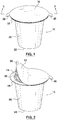
- Container 10 includes a body 12, filter 14, ingredients 16 and cover 18.
- Body 12 includes a side wall 20 and an end wall 22 together defining an enclosed interior space 24.
- An opening 26 is defined at one end of body 12.
- Body 12 further includes a flange 28 that extends around the perimeter of opening 26.
- side wall 20, end wall 22 and flange 26 are all integrally formed, such as by thermoforming, from one sheet of material.
- Container 10 preferably is symmetrical with an annular flange 28 having a uniform width. Most preferably, container 10 has a circular cross section in order that it does not require orientation during manufacture or during use (in cases where container is used in a machine for preparing beverages or other products).
- Cover 18 includes at least one tab 30 that is adapted to provide a grip for cover 18 to be peeled from body 12 following use of container 10 in a machine for preparing products, such as beverages, from containers 10.
- Tab 30 may extend from flange 28 and fold over or, more preferably, tab 30 is integrally formed with flange 28 as shown for example with the embodiment depicted in Figures 12 and 13 .
- Cover 18 is preferably formed of a material that is resistant to tearing upon the application of a peel force. Most preferably, cover 18 is formed of a multi-layered material that includes at least one layer that is resistant to tearing upon the application of a peel force. Cover 18, or a tear resistant layer of cover 18, preferably has a minimum tensile strength of 20.7 Mpa (3000 psi) and a minimum elongation of 50%. Examples of materials that are resistant to tearing include polyethylene (PE), polyethylene terephthalate (PET) and polyamide PA6.
- PE polyethylene
- PET polyethylene terephthalate
- PA6 polyamide PA6
- a multi- layered material for cover 18 may include at least one layer formed of a continuous film of tear resistant material (laminated or extrusion coated) or a non-continuous film such as a non-woven polymer, mesh or perforated film.
- a multi-layered material for cover 18 include (from outside layer to inside layer): PET/aluminum foil/PE, PET/EVOH/PE, PET/metalized PET/PE or PET/PE.
- End wall 22 includes at least one extraction region 32 adapted for being pierced by at least one extraction needle 34 of a machine 36 for dispensing product, such as a beverage, from the container 10 to a user's cup.
- Filter 14 is adapted to be disposed within body 12 to define at least one ingredients chamber 46 in an upper region of the interior space 24 for receiving one or more ingredients 16 and, for filtering applications, at least one extraction chamber 48 exterior to the ingredients chamber 46 in the interior space 24 for receiving product, such as a beverage, from the at least one ingredients chamber 46 prior to extraction using the extraction needle 34.
- Frter is defined herein to mean any material that is suitable for holding and filtering ingredients for preparing a beverage.
- “Ingredients” is defined herein to mean any material that is desired for use within container for a desired purpose. Ingredients may include food or beverage ingredients or other natural or synthetic material (for example packaging preservatives) desired for use within container.
- ingredients 16 may be coffee grounds, tea leaves, chocolate powder, milk powder, instant coffee or any other soluble or insoluble ingredients or combinations of ingredients that may be used to prepare a beverage in a beverage preparing machine 36 as described herein.
- Filter 14 includes a gasket portion 50 that is adapted for securing filter 14 to body 12 as described further below.
- Gasket portion 50 includes a plurality of pores, openings or channels 62 (collectively referred to as channels 62 hereafter) suitable for securing filter 14 between cover 18 and flange 28 as described herein.
- Filter 14 also includes a filter portion 52 that is disposed within interior space 24 to define ingredients chamber 46.
- filter portion 52 is molded to a desired shape within interior space 24 once gasket portion 50 has been secured to body 12 and prior to filling with ingredients 16.
- Filter 14 may be formed of any material suitable for holding and filtering the specific ingredients 16 that are intended to be disposed within ingredients chamber 46.
- filter 14 is formed of a moldable non-woven filtration material that includes a plurality of multi- component filaments that are bound or interlocked by non-woven manufacturing techniques (such as spunbond techniques) to form a web having channels 62 extending from one side of filter 14 to the other.
- the basis weight for filter 14 adapted for filtering ingredients for preparing a single serving of beverage is in the range of 8 to 400 grams per square meter (gsm), preferably in the range of 40 to 150 gsm and more preferably in the range of 60 to 120 gsm. More details of the preferred moldable nonwoven filtration material for filter 14 are provided in co-pending US provisional patent application No. 61/723,644 and regular US patent application 14/074,024 .
- Gasket portion 50 of filter 14 is adapted to be secured by way of a first bond 64 to the periphery of opening 16 of body 12 (and most preferably to the top surface of flange 28).
- First bond 64 may be formed by disposing a separate bonding material between filter 14 and body 12 or it may be integrally formed from the material of one or both of filter 14 and body 12 (as shown for example in Figure 5 ).
- First bond 64 preferably comprises a peelable bond between second surface 14b of filter 14 and first surface 12a of body 12 (top surface of flange 28) in order that filter 14 may be peeled away from body 12.
- Porelable bond is defined herein to mean a bond between two materials that is sufficiently strong to allow both materials to remain bonded together during normal conditions for manufacture, shipment and use while being sufficiently weak to allow one material to be peeled away from the other material by hand following use.
- First bond 64 is formed from a first bonding material 66 that is adapted for securing filter 14 to body 12.
- first bonding material 66 may be a separate material from filter 14 and body 12 or it may be an integral part of the material (either a monolayer material or a layer of a multi-layered material) for one or both of filter 14 and body 12.
- first bonding material 66 is a heat sealable polymer such as polyethylene (PE) including low density PE, linear low density PE and high density PE. This material may be provided as a sealing layer for a multi-layered material for body 12 or it may be provided as a separate first bonding material 66.
- PE polyethylene
- first bonding materials 66 include other heat sealable materials such as polypropylene, lacquer, ethylene vinyl acetate (EVA), ethylene acrylates, polystyrene or combinations of the above. Adhesive materials (having comparable adhesion properties as described above to form a peelable bond) may be utilized for applications where a heat sealer is not desired or feasible.
- Suitable first bonding materials that may be integral with filter 14 include homocomponent materials (such as polyolefin, polyester, and polyamide) and multicomponent materials (such as polyester-polyolefin, polyamide-polyolefin and polyester-polyamide).
- Cover 18 is adapted to be secured by way of a second bond 68 to gasket portion 50 of filter 14.
- second bond 68 preferably is at least as strong and more preferably is stronger than first bond 64 in order that filter 14 will remain secured to cover 18 when cover 18 is peeled from body 12.
- Second bond 68 is preferably formed from a second bonding material 70 that is adapted for securing a first surface 18a of cover 18 to second surface 14b of filter 14.
- a preferred second bonding material is a heat sealable polymer such as polyolefin.
- Other suitable second bonding materials 70 may include other heat sealable materials such as lacquer, ethylene vinyl acetate (EVA), and ethylene acrylates or adhesive materials for applications where a heat sealer is not desired or feasible.
- first bonding material 66 and second bonding material 70 are interdependent and also depend on the selection of other components within container 10 including filter 14.
- the strength or weakness of the bonds is related to the compatibility of the respective materials being bonded together. Less compatible bonds are adapted to separate prior to more compatible bonds. More details concerning the preferred choice of bonding materials are provided below with reference to Figures 6(a)-(d) .
- the bond strength of second bond 68 is preferably at least as strong as the first bond 64 and more preferably 50% higher than that of first bond 64 and even more preferably 100% higher or more.
- the bond strength of first bond 64 is preferably no more than 20 N/15 mm and more preferably no more than 10 N/15 mm.
- the bond strength of second bond 68 is preferably no less than 15 N/15 mm and more preferably no less than 25 N/15 mm.
- First and second bonding materials 66, 70 are preferably adapted to become at least partially embedded within channels 62 of gasket portion 50 of filter 14. Heat sealable polymers for example will flow into channels 62 when melted during a heat sealing process and then form a bond within channels 62 upon cooling. In the case of filter 14 being formed of filtration material having multi-component fibers, one or more portions of the multi-component fibers may melt during the heat sealing process and combine with the first or second bonding materials while other portions of the multi-component fibers remain intact (do not melt) during the heat sealing process to maintain a web defining channels 62.
- second bonding material 70 is chemically compatible in order that it may be sealed to all the components of filter material 14 to give a sufficiently strong seal strength. More details of filter 14 and the manner for securing filter 14 and cover 18 to flange 28 of body 12 are provided in co-pending patent application No 13/600,582 .
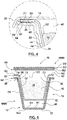
- FIG. 5 an exploded sectional view of a container 10 in accordance with another embodiment of the present invention is shown.
- the same reference numerals are provided for elements that are similar to the elements described above.
- Container 10 includes body 12, filter 14, ingredients 16 and cover 18. While the body 12 and cover 18 of container 10 shown in Figures 1-4 could be formed of a monolayered material, body 12 and cover 18 for the embodiment shown in Figure 5 are each formed of multilayered materials that include one or more barrier layers providing barriers against one or more environmental factors such as light, oxygen, and moisture as described further below.
- Body 12 is formed of a conventional multilayered material MM1 that includes a barrier layer B1 preferably formed of ethylene vinyl alcohol (EVOH) and a sealing layer S1 preferably formed of polyethylene (PE).
- a barrier layer B1 preferably formed of ethylene vinyl alcohol (EVOH) and a sealing layer S1 preferably formed of polyethylene (PE).
- body 12 may include outer base layer O1 preferably formed of polyolefin or polystyrene or other materials adapted to cover and protect barrier layer B1.
- Cover 18 is formed of a conventional multilayered material MM2 that includes a barrier layer B2 preferably formed of aluminum foil or metalized polyester or Ethylene Vinyl Alcohol (EVOH) and a sealing layer S2 preferably formed of polyethylene or modified polyethylene or polyethylene copolymer. Sealing layer S2 may be formed from a lamination process, extrusion coating or lacquer coating process. As well, cover 18 may include an outer base layer 02 preferably formed of polyester and a graphics layer G2 preferably formed of ink. Depending upon the the type of packing machinery, cover 18 could be provided as roll stock or in die-cut format.
- a barrier layer B2 preferably formed of aluminum foil or metalized polyester or Ethylene Vinyl Alcohol (EVOH)
- a sealing layer S2 preferably formed of polyethylene or modified polyethylene or polyethylene copolymer. Sealing layer S2 may be formed from a lamination process, extrusion coating or lacquer coating process.
- cover 18 may include an outer base layer 02 preferably formed of polyester and a graphics layer G2
- cover 18 is formed of multilayered material MM2 (such as described above) that is resistant to tearing as described above and that shrinks when exposed to heat. This allows cover to be peeled away from body 12 and also reduces the likelihood of cover 18 being torn during the process of puncturing with injection nozzle and injecting fluid into ingredients chamber 46. Multilayered material MM2 of cover 18 will also preferably shrink around the opening formed by injection nozzle when exposed to injection of hot fluid to reduce the size of opening. These characteristics can be achieved by choosing a proper outer base layer 02 such as polyester for providing rigidity to the cover 18.
- Filter 14 is formed by disposing filtration material over opening 26 of body 12. Gasket portion 50 of filter 14 engages sealing layer S1 disposed on the top surface of flange 28 and filter portion 52 extends across opening 26. Gasket portion 50 is then sealed with a heat sealer to sealing layer S1 disposed on the top surface of flange 28. A portion of sealing layer S1 on top surface of flange 28 (also referred to herein as first bonding material 66) is melted by heat sealer and flows into channels 62 within gasket portion 50. The gasket portion 50 of filter 14 may be partially melted during this process if it contains multiple component fibres while other portions of the multi-component fibers remain intact (do not melt) during the heat sealing process to maintain a web defining channels 62.
- the temperature, pressure and time parameters for the heat sealing process are optimized to ensure the desired bonding strength is achieved for both first bond 64 and second bond 68.
- the sealing temperature is preferably in the range of 100-250 C and more preferably in the range of 160-220 C.
- the sealing pressure is preferably in the range of 0.5-4 bar and more preferably in the range of 1-3 bar.
- the sealing time is preferably in the range of 50-5000 milliseconds and more preferably in the range of 500-3000 milliseconds.
- filter 14 may be molded for instance by engaging filter portion 52 using a heated mandrel to mold filter portion 52 to a desired shape within interior space of body 12 to form the ingredients chamber 46. Then ingredients 16 are disposed within ingredients chamber 46 of filter 14 and cover 18 is positioned over gasket portion 50 to cover opening 26.
- Cover 18 may then be partially sealed to gasket portion 50 using a heat sealer.
- a portion of the sealing layer S2 (also referred to herein as second bonding material 70) on bottom surface of cover 18 is melted by a heat sealer and flows into channels 62 of gasket portion 50.
- the air within interior space 16 of container 10 may then be evacuated and replaced with an inert gas such as nitrogen in accordance with a modified atmosphere packaging process.
- the remainder of cover 18 may then be fully sealed to body 12 over gasket portion 50 as described above to form second bond 68 and seal interior space 16 of container 10.
- Body 12 preferably includes a notch 72 cut into at least sealing layer S1 (first bonding layer 66) below the periphery of opening 16.
- Notch 72 may, in certain applications where barrier properties are not excessively compromised, also extend into barrier layer B1 if necessary to provide a sufficient area weakness as discussed below.
- Notch 72 provides an area of weakness for ingredients chamber and first bonding material 66 (in this instance sealing layer S1 at gasket 50) to be separated from body 12 when tab 30 is pulled to peel cover 18 from body 12 following use of container 10.
- Adhesion or tie layers T may be disposed in known manner between the respective layers B1, S1, O1 and G1 as described above to adhere or tie the respective layers together. Adhesion or tie layers T in body 12 may provide a relatively weak connection between adjoining surfaces to allow for separating layers when peeling cover 18 and ingredients chamber 46 from body 12.
- Figures 6(a) and 6(b) show first bond 64 being formed using a separate material (first bonding material 66) disposed between first surface 14a of filter 14 and first surface 12a of body 12.
- Filter 14 may be formed of ⁇ 20% LDPE or LLDPE and cover 18 may be formed of PE, EVA, EAA or a combination of two or more of these materials.
- first bonding material 66 and second bonding material 70 may be formed from LDPE, EVA (Dupont Bynel TM) or modified PE (Dow Sealution TM). It will be understood that other choices of materials may selected as well.
- Filter 14 may be formed of ⁇ 20% LDPE or LLDPE, PP, PA or Polyester and cover 18 may be formed of a PE, EVA, EAA or a combination of two or more of these materials.
- first bonding material 66 may be formed from LDPE, EVA (Dupont BynelTM) or modified PE (Dow SealutionTM).
- Second bonding material 70 may be formed from polyester or other suitable materials provided that the second bond 68 is stronger than first bond 64. It will be understood that other choices of materials may selected as well.
- Figures 6(c) and 6(d) show first bond 64 being integrally formed from a layer of a multilayered material MM1 forming body 12.
- the peel strength of the first bond 64 between first surface 14a of filter 14 and first bonding material 66 (which is the sealing layer S1 of the multilayered material MM1 forming body 12) is greater than the peel strength of the first bond 64 between first bonding material 66 and the adjacent layer of the multilayered material MM1.
- the adjacent layer may be a tie layer formed of a low compatibility material such as Surlyn TM or Bynel TM or adjacent layer may be barrier layer B1.
- filter 14 and first bonding material 66 ie a portion of the sealing layer S1 of multilayered material MM1 are peeled away upon the application of a sufficient peeling force to filter 14. This example is described in more detail above with reference to Figure 5 .
- Notch 72 defines a break point to allow a portion of sealing layer S1 to be removed with filter 14 while the remainder of sealing layer S1 stays within body 12.
- Filter 14 may be formed of ⁇ 20% LDPE or LLDPE, PP, PA or Polyester and cover 18 may be formed from PE, EVA, EAA or a combination of two or more of these materials .
- first bonding material 66 may be formed from LDPE, LLDPE, HDPE, EVA or a combination of two or more of these materials.
- Second bonding material 70 may be formed from PE, EVA, EAA or a combination of two or more of these materials. It will be understood that other choices of materials may selected as well.
- the peel strength of the first bond 64 between first surface 14a of filter 14 and first bonding material 66 is less than the peel strength of the first bond 64 between first bonding material 66 and the adjacent layer of the multilayered material MM1.
- filter 14 is peeled away from first bonding material 66 (ie away from first surface 12a of body 12 or, in other words, away from sealing layer S1 of multilayered material MM1 that forms body 12) upon the application of a sufficient peeling force to filter 14.
- Filter 14 may be formed of ⁇ 20% LDPE or LLDPE and cover 18 may be formed of PE, EVA, EAA or a combination of two or more of these materials.
- first bonding material 66 (sealing layer S1) may be formed from HDPE, PP or PS.
- Second bonding material 70 may be formed from PE, EVA, EAA or a combination of two or more of these materials. It will be understood that other choices of materials may selected as well.
- FIG. 7 a container 10 in accordance with another embodiment of the present invention is shown.
- the same reference numerals are provided for elements that are similar to the elements described above.
- Container 10 includes body 12, filter 14, ingredients 16 and cover 18. If desired, body 12 and cover 18 may each be formed of multilayered materials that include one or more barrier layers providing barriers against one or more environmental factors such as light, oxygen, and moisture as described further below.
- second bond 68 between filter 14 and cover 18 comprises a peelable bond similar to first bond 64 as described for the embodiments above.
- the peel strength of the second bond 68 between second surface 14b of filter 14 and second bonding material 70 may be less than the peel strength of the second bond 68 between second bonding material 70 and the first surface 18a of cover 18.
- filter 14 may be peeled away from second bonding material 70 (ie away from first surface 18a of body 12) upon the application of a sufficient peeling force to filter 14.
- Filter 14 and cover 18 also preferably each include tabs 30a and 30b that are preferably aligned to provide a common grip for peeling filter 14, ingredients 16 and cover 18 from body 12. Tabs 30a and 30b may then be separately gripped to peel cover 18 away from filter 14 and ingredients 16. This allows the user to dispose of body 12, filter 14, ingredients 16 and cover 18 in one of multiple desired locations.
- Filter 14 may be formed of ⁇ 20% LDPE or LLDPE and cover 18 may be formed of HDPE, PP or PS.
- first bonding material 66 (sealing layer S1) and second bonding material 70 (sealing layer S2) may be formed from HDPE, PP or PS.
- filter 14 may be formed of ⁇ 20% LDPE or LLDPE, PP, PA or Polyester and cover 18 may be formed from LDPE, LLDPE, HDPE, EVA or a combination of these materials.
- first bonding material 66 (sealing layer S1) and second bonding material 70 (sealing layer S2) may be formed from LDPE, LLDPE, HDPE, EVA or a combination of these materials. It will be understood that other choices of materials may selected as well.
- FIG. 8 a container 10 in accordance with another embodiment of the present invention is shown.
- the same reference numerals are provided for elements that are similar to the elements described above.
- Container 10 includes body 12, filter 14, ingredients 16 and cover 18. If desired, body 12 and cover 18 may each be formed of multilayered materials that include one or more barrier layers providing barriers against one or more environmental factors such as light, oxygen, and moisture as described further below.
- filter 14 is secured to sidewall 20 of body 12 by way of first bond 64 using first bonding material 66.
- First bond 64 is a peelable bond as described above.
- Filter 14 includes tab 30a that provides a grip for peeling filter 14 from body 12. Tab 30a is preferably folded away from flange 28.
- Cover 18 is secured to flange 28 of body 12 by way of second bond 68 using second bonding material 70.
- Second bond 68 is also a peelable bond as described above.
- Cover 18 includes tab 30b that provides a grip for peeling cover 18 from body 12.
- Filter 14 may be formed of ⁇ 20% LDPE or LLDPE and cover 18 may be formed of LDPE, LLDPE, HDPE, EVA, modified PE or a combination of these materials.
- first bonding material 66 (sealing layer S1) and second bonding material 70 (sealing layer S2) may be formed from HDPE, PP or PS.
- filter 14 may be formed of ⁇ 20% LDPE or LLDPE, PP, PA or Polyester and cover 18 may be formed from LDPE, LLDPE, HDPE, EVA or a combination of these materials.
- first bonding material 66 (sealing layer S1) and second bonding material 70 (sealing layer S2) may be formed from LDPE, LLDPE, HDPE, EVA or a combination of these materials. It will be understood that other choices of materials may selected as well.
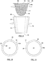
- FIG. 9-11 a container 10 in accordance with another embodiment of the present invention is shown.
- the same reference numerals are provided for elements that are similar to the elements described above.
- Container 10 includes body 12, filter 14, ingredients 16 and cover 18. If desired, body 12 and cover 18 may each be formed of multilayered materials that include one or more barrier layers providing barriers against one or more environmental factors such as light, oxygen, and moisture as described further below.
- this embodiment provides a separation of one portion of body 12, such as flange 28, from the rest of body 12.
- Cover 18 with filter 14 defining ingredients chamber 46 containing ingredients 16 remains connected to the removed portion of body 12, such as flange 28, following such separation.
- a separation point 80 is defined in body 12 preferably proximate to the interface between flange 28 and side wall 20.
- Separation point 80 may be a score line (a continuous indentation) or perforation line (a line of discrete indentations) that is adapted to break or separate upon the application of force.
- Separation point 80 may be defined in body 12 either during or following the process for forming body 12 for instance by thermoforming.
- the separation point 80 may be defined only in the outer surface (second surface 12b) of body 12 or it may be defined in both the outer surface and inner surfaces (second surface 12b and first surface 12a) of body 12.
- separation point 80 is formed through an in-mold cutting process during thermoforming of body 12 or at a separate station following formation of body 12.
- separation point 80 may extend about circumference of body 12 and be adapted to separate upon application of opposing twisting forces to flange 28 and side wall 20 (as shown in figure 6 ) similar to twisting a cap from a bottle. Separation point 80 is shown defined in flange 28 adjacent to the interface with side wall 20. It will be understood that separation point 80 could alternatively be defined in side wall 20 proximate to interface with flange 28. Filter 14 may be bonded to side wall 20 between separation point 22 and flange 28. Filter 14 is preferably formed of a non-woven material as described above but may alternatively be formed from a conventional paper filter material if desired since it is not subjected to significant tear forces.
- separation point 80 may be defined in flange 28 about circumference of body 12 and include a portion extending to peripheral wall of flange 28 to define tab 30 for peeling flange 28 with cover 18 and filter 14 with ingredients chamber 46 from the remainder of body 12.
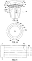
- FIG. 12-13 a container 10 in accordance with another embodiment of the present invention is shown.
- the same reference numerals are provided for elements that are similar to the elements described above.
- Container 10 includes body 12, filter 14, ingredients 16 and cover 18. If desired, body 12 and cover 18 may each be formed of multilayered materials that include one or more barrier layers providing barriers against one or more environmental factors such as light, oxygen, and moisture as described further below.
- cover 18 is bonded with second bonding material 68 to the first surface 12a of body 12 (top surface of flange 28) in the same manner as described for the embodiments shown in Figures 1-6 .
- a separation point 80 is defined along at least one portion of body 12, such as flange 28, to form at least one tab 30 (and preferably two tabs 30 as shown). Separation point 80 may be formed for example by a score line or perforation line that is adapted to break or separate from flange 28 upon the application of sufficient force. The force for instance may be applied by upward pressure, for instance by a person's thumb, along the bottom side of tab 30 until tab 30 snaps and separates from flange 28.
- Separation point 80 is preferably made through scoring or perforating during the same operation that is utilized for thermoforming body 12 or at a subsequent station. Separation point 80 may be defined along the second surface 12b of body 12 (bottom surface of flange 28) without significantly disrupting or negatively impacting the ability of cover 18 to be peelably sealed to the top surface of flange 28 such as described for the embodiments shown in Figures 1-6 . Separation point 80 may for instance extend a desired distance into the bottom surface of flange 28 without breaking the top surface. Preferably, separation point 80 is defined in both the outer surface and inner surfaces (second surface 12b and first surface 12a) of body 12. Preferably, for containers 10 formed of multilayered materials MM, separation point 80 does not break or significantly disrupt the barrier layer B.
- a tab indicator 82 is disposed on body 12 to indicate the location of tab 30.
- Tab indicator may be embossed onto the outer surface of sidewall 20 of body 12 in the same operation utilized for thermoforming body 12.
- Tab indicator 82 may alternatively be printed or adhered onto the material for forming body 12 at locations that align with the molds 84 that are adapted for formation of body 12 and separation point 80 as shown in Figure 14 .
- a user will apply force to tab 30 along the bottom portion of tab 30 until the tab 30 snaps free from the remainder of flange 28 along separation point 80. The user may hear a snap sound to indicate that tab 30 has separated from flange 28. The user then applies a peeling force to tab 30 in order to peel cover 18 and filter 14 with ingredients chamber containing ingredients 16 from body 12. Body 12 may be disposed into plastics recycling and cover 18 and filter 14 with ingredients chamber and ingredients 16 may be disposed into garbage destined for landfill or further processed or separated for disposal or recycling purposes.
- container 10 preferably is symmetrical with an annular flange 28 having a uniform width W with separation point 80 defining tab 30 within the uniform width W of flange 28. This is preferable to having a portion of flange 28 with tab 30 extend beyond the uniform width W of the remainder of flange 28 which could complicate the manufacture and packaging of container 10 and which may prevent conta8iner from being utilized in a machine 36.
- FIG. 15 and 16 a container 10 in accordance with another embodiment of the present invention is shown.
- the same reference numerals are provided for elements that are similar to the elements described above.
- Container 10 includes body 12, ingredients 16 and cover 18. If desired, body 12 and cover 18 may each be formed of multilayered materials that include one or more barrier layers providing barriers against one or more environmental factors such as light, oxygen, and moisture as described further below.
- This embodiment of container 10 is similar to the embodiment shown in Figure 12 and 13 but does not include filter 14.
- a tab 30 is defined in body 12 (preferably in flange 28) by separation point 80.
- Cover 18 is bonded by second bond 68 to the portion of body 12 (preferably to flange 28) that includes tab 30 defined by separation point 80.
- Second bond 68 is a peelable bond as described above to allow cover 18 to be peeled away with tab 30 from the remainder of body 12.
- Tab indicator 82 is provided, as described above, to assist the user in locating tab 30.
- This embodiment may be applied to a wide variety of containers 10.
- the separation point 80 defining tab 30 may be integrally formed within the body 12 of container 10 without adding significant costs or adding significant complexity to the overall structure of the container.
- FIG. 17 a container 10 in accordance with another embodiment of the present invention is shown.
- the same reference numerals are provided for elements that are similar to the elements described above.
- Container 10 includes body 12, filter 14, ingredients 16 and cover 18.
- body 12 comprises flange 28 and a partial side wall 20 adapted to support filter 14.
- Body 12 does not include a full side wall 20 and end wall 22 for defining a fully enclosed interior space.
- container 10 is similar to the embodiments described above with a portion of container 10 being removable from the remainder of container 10.
- filter 14 may be bonded to body 12 (either to flange 28 or side wall 20) with a first bond 64 that is a peelable bond.
- Cover 18 may be bonded to filter 14 or to body 12 (such as to flange 28) with a second bond that may also be a peelable bond if desired.
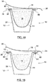
- FIG. 18 a container 10 in accordance with another embodiment of the present invention is shown.
- the same reference numerals are provided for elements that are similar to the elements described above.
- Container 10 includes body 12, filter 14, ingredients 16 and cover 18. If desired, body 12 and cover 18 may each be formed of multilayered materials that include one or more barrier layers providing barriers against one or more environmental factors such as light, oxygen, and moisture as described further below.
- body 12 further comprises a shoulder 90 disposed inwardly from flange 28 to support filter 14.
- Filter 14 may be bonded to a support ring 92 that is adapted to either rest loosely upon shoulder 90 as shown or be bonded to shoulder with a first bond 64 that is preferably a peelable bond (not shown).
- Cover 18 is bonded to flange 28 with second bond 68 that is a peelable bond as described for the embodiments above.
- container allows filter 14 to be disposed within container 10 without bonding to the same flange surface as cover 18.
- filter 14 and ingredients 16 may be removed from container either by tipping container upside down (if ring rests loosely upon shoulder 90) or by peeling away ring and filter 14 preferably with the aid of a tab (not shown).
- FIG. 19 a container 10 in accordance with another embodiment of the present invention is shown.
- the same reference numerals are provided for elements that are similar to the elements described above.
- Container 10 includes body 12, filter 14, ingredients 16 and cover 18. If desired, body 12 and cover 18 may each be formed of multilayered materials that include one or more barrier layers providing barriers against one or more environmental factors such as light, oxygen, and moisture as described further below.
- container 10 is similar to the container shown in Figure 18 .
- Shoulder 90 includes a slot 94 that is adapted to receive a portion of filter 14 and support ring 92.
- Support ring 92 is preferably configured to support filter 14 within slot 94 by way of a friction fit.
- container also allows filter 14 to be disposed within container 10 without bonding to the same flange surface as cover 18.
- filter 14 and ingredients 16 may be removed from container by peeling away ring and filter 14 preferably with the aid of a tab 30.
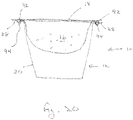
- FIG. 20 a container 10 in accordance with another embodiment of the present invention is shown.
- the same reference numerals are provided for elements that are similar to the elements described above.
- Container 10 includes body 12, filter 14, ingredients 16 and cover 18. If desired, body 12 and cover 18 may each be formed of multilayered materials that include one or more barrier layers providing barriers against one or more environmental factors such as light, oxygen, and moisture as described further below.
- container 10 is similar to the container shown in Figure 19 however no shoulder 90 is provided. Instead, slot 94 is defined in flange 28. Slot 94 is adapted to receive a portion of filter 14 and support ring 92.
- Cover 18 is bonded to support ring 92 as well as to flange 28 by a peelable bond. Upon peeling away cover 18 following the use of container 10, filter 14 and ingredients 16 may be removed from container.
Landscapes
- Engineering & Computer Science (AREA)
- Mechanical Engineering (AREA)
- Packages (AREA)
Claims (15)
- Récipient (10) comprenant :un corps (12) définissant un espace intérieur (24) ayant une ouverture (26), ledit corps ayant une bride (28) entourant ladite ouverture ;un filtre (14) disposé dans ledit corps afin de définir une chambre d'ingrédients (46), ledit filtre étant adhérisé à une première surface (12a) de ladite bride au moyen d'une première liaison (64), ladite première liaison étant une liaison détachable ;un point de séparation (80) défini dans ladite bride, ledit point de séparation définissant une languette (30) qui est adaptée pour être séparée du reste de ladite bride suite à l'application de la force suffisante à la main ;des ingrédients (16) disposés dans ladite chambre d'ingrédients ; etun couvercle (18) disposé sur ladite ouverture pour recouvrir ledit espace intérieur, le couvercle étant adhérisé audit filtre au moyen d'une seconde liaison (68),dans lequel ladite languette et ledit couvercle sont adaptés pour être retirés conjointement avec ledit filtre et ladite chambre d'ingrédients contenant lesdits ingrédients, suite à l'utilisation du récipient par l'application d'une force à la main, caractérisé en ce que ledit filtre est formé avec un matériau approprié pour contenir et filtrer lesdits ingrédients pour la préparation d'une boisson.
- Récipient selon la revendication 1, dans lequel ledit filtre est formé avec un matériau de filtration non tissé moulable.
- Récipient selon la revendication 1 ou 2, dans lequel ledit filtre définit en outre une chambre d'extraction (48) à l'extérieur de ladite chambre d'ingrédients.
- Récipient selon l'une quelconque des revendications 1 à 3, dans lequel une encoche (72) est définie dans la surface intérieure dudit corps, ladite encoche fournissant un point prédéterminé de faiblesse dans ledit corps.
- Récipient selon la revendication 4, dans lequel ladite encoche s'étend sensiblement autour de la périphérie de ladite ouverture.
- Récipient selon la revendication 4, dans lequel ledit corps est formé avec un matériau multicouche (MM1) qui comprend une couche de barrière (B1) disposée entre une couche d'étanchéité (S1) et une couche externe (O1), et dans lequel ladite encoche est définie dans ladite couche d'étanchéité.
- Récipient selon l'une quelconque des revendications précédentes, dans lequel ledit corps est formé avec un matériau multicouche qui comprend une couche de barrière disposée entre une couche d'étanchéité et une couche externe, et dans lequel ladite première liaison entre ledit filtre et ledit corps est formée avec ladite couche d'étanchéité.
- Récipient selon l'une quelconque des revendications précédentes, dans lequel ledit filtre a une partie de joint (50) avec une pluralité de canaux (62), et dans lequel un premier matériau de liaison (66) est disposé dans au moins certains desdits canaux pour former ladite première liaison entre ledit filtre et ladite bride.
- Récipient selon la revendication 8, dans lequel un second matériau de liaison (70) est disposé dans au moins certains desdits canaux pour former ladite seconde liaison entre ledit filtre et ledit couvercle.
- Récipient selon la revendication 9, dans lequel au moins l'un parmi ledit premier matériau de liaison et ledit second matériau de liaison est un polymère thermosoudable.
- Récipient selon l'une quelconque des revendications précédentes, dans lequel ladite première liaison a une résistance de liaison qui est supérieure à la résistance de liaison de la première liaison.
- Récipient selon la revendication 11, dans lequel ladite première liaison a une résistance de liaison non supérieure à 20 N/15 mm.
- Récipient selon la revendication 11, dans lequel ladite seconde liaison a une résistance de liaison non inférieure à 15 N/15 mm.
- Capsule de boisson à dose unique comprenant un récipient selon l'une quelconque des revendications précédentes et une quantité d'un ingrédient de boisson prévu à l'intérieur de ladite chambre d'ingrédients.
- Capsule de boisson à dose unique selon la revendication 14, dans laquelle l'ingrédient de boisson est du café moulu.
Priority Applications (1)
| Application Number | Priority Date | Filing Date | Title |
|---|---|---|---|
| EP17152912.6A EP3178758B1 (fr) | 2012-12-07 | 2013-12-06 | Réceptacle à partie amovible |
Applications Claiming Priority (3)
| Application Number | Priority Date | Filing Date | Title |
|---|---|---|---|
| US201261734667P | 2012-12-07 | 2012-12-07 | |
| US201361760880P | 2013-02-05 | 2013-02-05 | |
| PCT/CA2013/050941 WO2014085934A1 (fr) | 2012-12-07 | 2013-12-06 | Réceptacle à partie amovible |
Related Child Applications (1)
| Application Number | Title | Priority Date | Filing Date |
|---|---|---|---|
| EP17152912.6A Division EP3178758B1 (fr) | 2012-12-07 | 2013-12-06 | Réceptacle à partie amovible |
Publications (3)
| Publication Number | Publication Date |
|---|---|
| EP2928792A1 EP2928792A1 (fr) | 2015-10-14 |
| EP2928792A4 EP2928792A4 (fr) | 2015-11-11 |
| EP2928792B1 true EP2928792B1 (fr) | 2017-01-25 |
Family
ID=50881209
Family Applications (2)
| Application Number | Title | Priority Date | Filing Date |
|---|---|---|---|
| EP17152912.6A Active EP3178758B1 (fr) | 2012-12-07 | 2013-12-06 | Réceptacle à partie amovible |
| EP13860496.2A Active EP2928792B1 (fr) | 2012-12-07 | 2013-12-06 | Réceptacle à partie amovible |
Family Applications Before (1)
| Application Number | Title | Priority Date | Filing Date |
|---|---|---|---|
| EP17152912.6A Active EP3178758B1 (fr) | 2012-12-07 | 2013-12-06 | Réceptacle à partie amovible |
Country Status (7)
| Country | Link |
|---|---|
| US (1) | US20140161936A1 (fr) |
| EP (2) | EP3178758B1 (fr) |
| KR (1) | KR20150093741A (fr) |
| CN (1) | CN105073606B (fr) |
| AU (2) | AU2013354828A1 (fr) |
| CA (1) | CA2888658C (fr) |
| WO (1) | WO2014085934A1 (fr) |
Cited By (1)
| Publication number | Priority date | Publication date | Assignee | Title |
|---|---|---|---|---|
| TWI750978B (zh) * | 2020-12-28 | 2021-12-21 | 禾益佳股份有限公司 | 具方便提取功能的盒體 |
Families Citing this family (49)
| Publication number | Priority date | Publication date | Assignee | Title |
|---|---|---|---|---|
| US10722066B2 (en) * | 2010-12-04 | 2020-07-28 | Adrian Rivera | Windowed single serving brewing material holder |
| US11832755B2 (en) * | 2007-07-13 | 2023-12-05 | Adrian Rivera | Brewing material container for a beverage brewer |
| PL3521207T3 (pl) | 2010-07-22 | 2020-06-15 | K-Fee System Gmbh | Kapsułka porcyjna z kodem kreskowym |
| DE102012105282A1 (de) | 2012-06-18 | 2013-12-19 | K-Fee System Gmbh | Portionskapsel und Verfahren zur Herstellung eines Getränks mit einer Portionskapsel |
| ITTV20120146A1 (it) * | 2012-07-30 | 2014-01-31 | Hausbrandt Trieste 1892 Spa | Capsula per la preparazione di bevande |
| KR20150093741A (ko) | 2012-12-07 | 2015-08-18 | 2266170 온타리오 인크. | 제거가능한 부분을 갖는 용기 |
| DE102012223291A1 (de) | 2012-12-14 | 2014-06-18 | K-Fee System Gmbh | Portionskapsel und Verfahren zur Herstellung eines Getränks mit einer Portionskapsel |
| ITMO20130046A1 (it) * | 2013-02-22 | 2014-08-23 | Sarong Spa | Metodo per realizzare una capsula da bevande e capsula |
| US20140377414A1 (en) * | 2013-06-25 | 2014-12-25 | William J. Walters | Single Serve Cup |
| USD732390S1 (en) * | 2013-08-15 | 2015-06-23 | 2266170 Ontario Inc. | Capsule |
| USD731890S1 (en) * | 2013-08-15 | 2015-06-16 | 2266170 Ontario Inc. | Capsule |
| USD731884S1 (en) * | 2013-08-15 | 2015-06-16 | 2266170 Ontario Inc. | Capsule |
| USD735574S1 (en) * | 2014-02-11 | 2015-08-04 | The Quaker Oats Company | Cup |
| USD769726S1 (en) * | 2014-03-21 | 2016-10-25 | 2266170 Ontario Inc. | Capsule with logo |
| USD770286S1 (en) | 2014-03-21 | 2016-11-01 | 2266170 Ontario Inc. | Capsule |
| USD753491S1 (en) * | 2014-03-21 | 2016-04-12 | 2266170 Ontario Inc. | Capsule |
| USD757536S1 (en) * | 2014-10-01 | 2016-05-31 | Kraft Foods Group Brands Llc | Container |
| US9938075B2 (en) * | 2014-11-26 | 2018-04-10 | The Procter & Gamble Company | Beverage cartridge containing pharmaceutical actives |
| USD757537S1 (en) * | 2014-12-11 | 2016-05-31 | 2266170 Ontario Inc. | Capsule |
| RU2017133486A (ru) | 2015-02-27 | 2019-03-27 | К-Фее Зюстем Гмбх | Порционная капсула с прикрепленным посредством термосварки фильтрующим элементом |
| USD778157S1 (en) * | 2015-04-13 | 2017-02-07 | 2266170 Ontario Inc. | Capsule |
| ES2791960T3 (es) | 2015-06-09 | 2020-11-06 | K Fee System Gmbh | Cápsula monodosis, sistema y procedimiento para la preparación de una bebida |
| AU2016274658B2 (en) | 2015-06-10 | 2020-11-05 | K-Fee System Gmbh | Portion capsule with a three-ply nonwoven fabric |
| ITUB20151957A1 (it) * | 2015-07-03 | 2017-01-03 | Libero Facchini | Capsula per la preparazione di una bevanda |
| CN104970702B (zh) * | 2015-07-08 | 2017-12-26 | 亘嘉科技(杭州)有限公司 | 一种全自动胶囊盒去皮出料装置 |
| CN107848699A (zh) | 2015-07-13 | 2018-03-27 | K-Fee系统股份有限公司 | 具有切口的过滤元件 |
| ITUB20153161A1 (it) * | 2015-08-19 | 2017-02-19 | Lavazza Luigi Spa | Cartuccia per la preparazione di un prodotto liquido e procedimento per realizzarla |
| DE202015008067U1 (de) * | 2015-09-01 | 2016-12-02 | LigaLife GmbH & Co. KG | Kapsel für eine Erzeugung eines flüssigen Lebensmittels |
| DE102015115249A1 (de) * | 2015-09-10 | 2017-03-16 | Pester Pac Automation Gmbh | Verpackung |
| RU2018113775A (ru) | 2015-09-18 | 2019-10-18 | К-Фее Зюстем Гмбх | Адаптер для порционной капсулы |
| US11001436B2 (en) * | 2016-06-09 | 2021-05-11 | Keurig Green Mountain, Inc. | Beverage cartridge |
| EP3317205B1 (fr) | 2016-07-06 | 2019-01-02 | Nestec S.A. | Emballage recyclable comprenant une poche souple |
| USD823051S1 (en) * | 2016-08-04 | 2018-07-17 | Shankar Sharma | Pod |
| SE1651238A1 (en) * | 2016-09-19 | 2018-03-20 | Sveadanerna Food Ab | A capsule with a barrier-layer for preparing a beverage |
| EP3348495A1 (fr) * | 2017-01-17 | 2018-07-18 | Delica AG | Corps de capsule d'une capsule |
| NL2019220B1 (en) * | 2017-07-10 | 2019-01-16 | Douwe Egberts Bv | Capsule and system for preparing a crema-free coffee beverage |
| KR101947530B1 (ko) * | 2017-08-24 | 2019-02-13 | 이의선 | 원두 커피 드립 백 |
| US11440717B2 (en) * | 2017-08-25 | 2022-09-13 | Adrian Rivera | Espresso cartridge with improved sealing to espresso machine |
| CN111629980B (zh) * | 2017-11-29 | 2022-02-25 | 戈利奥有限公司 | 用于可溶性或可提取产品的胶囊 |
| KR20190070000A (ko) * | 2017-12-12 | 2019-06-20 | 주식회사 아로마빌커피 | 음료추출용기가 구비된 음료컵 |
| CA3094348C (fr) | 2018-04-23 | 2021-06-29 | 2266170 Ontario Inc. | Capsules et autres contenants presentant des attributs de recyclage optimises et leurs procedes de fabrication |
| US11523702B1 (en) * | 2018-05-10 | 2022-12-13 | Charles F O'Toole, III | Infuser implement and method of manufacture |
| US10881582B2 (en) | 2018-06-11 | 2021-01-05 | Glaxosmithkline Consumer Healthcare Holdings (Us) Llc | Individual dose pack |
| USD909195S1 (en) * | 2019-03-05 | 2021-02-02 | Compagnie Gervais Danone | Food product container |
| USD1003713S1 (en) * | 2019-05-28 | 2023-11-07 | Constantia Teich Gmbh | Food container lid |
| WO2020242579A1 (fr) | 2019-05-31 | 2020-12-03 | Sung Oh | Commande de paramètres d'infusion d'un système de boisson à usage unique |
| EP4077166A1 (fr) * | 2019-12-18 | 2022-10-26 | Société des Produits Nestlé S.A. | Contenant à languette |
| US20220227574A1 (en) * | 2020-01-30 | 2022-07-21 | Sung Oh | Draining the Beverage From a Single-Serve Beverage Pod With or Without an Outlet Piercing Element |
| US11805934B1 (en) * | 2020-10-21 | 2023-11-07 | Adrian Rivera | Brewing material lid and container for a beverage brewer |
Family Cites Families (40)
| Publication number | Priority date | Publication date | Assignee | Title |
|---|---|---|---|---|
| DE2129070B2 (de) | 1971-06-11 | 1974-08-29 | Joh. Jacobs & Co Gmbh, 2800 Bremen | Vorrichtung zur maschinellen Zubereitung eines Kaffeegetränks aus über eine Fördereinrichtung einer Brühstation zugeführten Kaffeeportionen |
| CH605293A5 (fr) | 1976-12-17 | 1978-09-29 | Nestle Sa | |
| KR870000045A (ko) | 1985-06-28 | 1987-02-16 | 가다오가 죠지 | 커피 여과기 |
| US5178293A (en) | 1986-04-08 | 1993-01-12 | Idemitsu Petrochemical Co., Ltd. | Easily-openable packaging container |
| DE3623952A1 (de) * | 1986-07-16 | 1988-01-28 | Erich H Dipl Ing Woltermann | Filter zum portionierten aufbruehen von kaffee oder tee |
| KR890004671A (ko) | 1987-09-21 | 1989-05-09 | 가다야마 유다까 | 의료용 트레이 |
| US5840189A (en) | 1992-09-16 | 1998-11-24 | Keurig, Inc. | Beverage filter cartridge |
| US5424083A (en) * | 1994-10-24 | 1995-06-13 | Lozito; Michael C. | Self contained disposable coffee brewing device |
| US6516949B2 (en) * | 1995-10-31 | 2003-02-11 | Mcneil-Ppc, Inc. | Blister pill package with safety backing |
| US6007853A (en) | 1997-03-07 | 1999-12-28 | Dbf, Inc. | Disposable beverage infuser |
| JP3027382B1 (ja) * | 1998-07-24 | 2000-04-04 | 株式会社ヨコタ | 易リサイクル性容器 |
| EP1164093B1 (fr) * | 1998-12-09 | 2005-09-07 | Nissin Shokuhin Kabushiki Kaisha | Element de couvercle ameliore pour recipient alimentaire |
| EP1247756B1 (fr) | 2001-04-03 | 2004-12-01 | Societe Des Produits Nestle S.A. | Capsule fermée pour la préparation de boissons |
| ITPD20010284A1 (it) * | 2001-12-07 | 2003-06-09 | Bp Europack Spa | Foglio composto da piu' films per la realizzazione di coperchi di contenitori in materia plastica a distacco per pelabilita' con apertura pr |
| KR100535744B1 (ko) | 2002-03-07 | 2006-01-10 | 넥솔테크(주) | 액상식품 추출용 밀봉 용기 |
| DE10352444A1 (de) * | 2003-11-10 | 2005-06-09 | Mitsubishi Polyester Film Gmbh | Haftvermittelte, heißsiegelbare und peelfähige Polyesterfolie, Verfahren zu ihrer Herstellung und ihre Verwendung |
| DE102004002005A1 (de) | 2004-01-14 | 2005-08-11 | Schifferle, René | Portionskapsel mit gemahlenem Kaffee zur Herstellung eines Kaffeegetränks |
| US7371008B2 (en) * | 2004-07-23 | 2008-05-13 | Kraft Foods Holdings, Inc. | Tamper-indicating resealable closure |
| GB0423556D0 (en) * | 2004-10-22 | 2004-11-24 | Kraft Foods R & D Inc | Pod for preparing a beverage |
| JP4610357B2 (ja) * | 2005-01-31 | 2011-01-12 | 出光ユニテック株式会社 | 易開封性容器の製造方法 |
| US20070131687A1 (en) * | 2005-12-14 | 2007-06-14 | Unique Seal, Llc | Package having multiple sealed compartments |
| US8308363B2 (en) * | 2006-05-23 | 2012-11-13 | Kraft Foods Global Brands Llc | Package integrity indicator for container closure |
| ITMO20060308A1 (it) | 2006-09-29 | 2008-03-30 | Coopbox Europ S P A | Confezione per un prodotto alimentare. |
| DE602008006068D1 (de) * | 2007-06-05 | 2011-05-19 | Nestec Sa | Verfahren zur herstellung eines getränks oder flüssigen nahrungsmittels |
| BRPI0812449B1 (pt) * | 2007-06-05 | 2018-09-25 | Nestec Sa | cápsula para a preparação de alimento líquido por meio de centrifugação |
| RU2470847C2 (ru) | 2008-01-29 | 2012-12-27 | Конинклейке Дауве Егбертс Б.В. | Система, способ и капсула для приготовления напитка |
| KR101237783B1 (ko) * | 2009-03-19 | 2013-02-28 | 주식회사 블리스팩 | 재활용이 가능한 포장용기의 제조 시스템 |
| CA2765468A1 (fr) | 2009-06-17 | 2010-12-02 | Sara Lee/De B.V. | Capsule, systeme et procede pour la preparation d'une boisson et procede de fabrication d'une telle capsule |
| US20110027199A1 (en) * | 2009-07-30 | 2011-02-03 | Danny Frye | Drink container with a breath strip |
| US9527661B2 (en) * | 2009-09-29 | 2016-12-27 | Lbp Manufacturing Llc | Disposable single use beverage package |
| US8361527B2 (en) | 2010-09-02 | 2013-01-29 | Keurig, Incorporated | Beverage cartridge |
| US8895090B2 (en) * | 2010-09-22 | 2014-11-25 | K-Fee System Gmbh | Portion capsule and method for producing the same |
| US20120097602A1 (en) * | 2010-10-22 | 2012-04-26 | International Paper Company | Biodegradable or compostable beverage filter cartridge |
| US9469471B2 (en) | 2011-02-03 | 2016-10-18 | 2266170 Ontario Inc. | Beverage capsule |
| US8906440B2 (en) * | 2011-06-16 | 2014-12-09 | Javajig, Llc | Coffee filter basket |
| US8684212B2 (en) * | 2011-07-18 | 2014-04-01 | Joseph Stone | Tamper-evident container that indicates when the container has been tampered with or opened |
| ITMI20112157A1 (it) * | 2011-11-25 | 2013-05-26 | Novacart Spa | Procedimento per realizzare un supporto tubolare, capsula per la preparazione di bevande alimentari incorporante il supporto tubolare e metodo produttivo della stessa capsula |
| KR20150093741A (ko) | 2012-12-07 | 2015-08-18 | 2266170 온타리오 인크. | 제거가능한 부분을 갖는 용기 |
| CA2902231C (fr) * | 2013-02-25 | 2016-02-09 | 2266170 Ontario Inc. | Capsule contenant une seule portion permettant d'obtenir une efficacite d'extraction et une retention d'arome ameliorees |
| US20140287099A1 (en) * | 2013-03-25 | 2014-09-25 | 2266170 Ontario Inc. | Capsule With Messaging System |
-
2013
- 2013-12-06 KR KR1020157017714A patent/KR20150093741A/ko not_active Application Discontinuation
- 2013-12-06 EP EP17152912.6A patent/EP3178758B1/fr active Active
- 2013-12-06 EP EP13860496.2A patent/EP2928792B1/fr active Active
- 2013-12-06 CN CN201380072483.XA patent/CN105073606B/zh not_active Expired - Fee Related
- 2013-12-06 WO PCT/CA2013/050941 patent/WO2014085934A1/fr active Application Filing
- 2013-12-06 CA CA2888658A patent/CA2888658C/fr active Active
- 2013-12-06 US US14/098,915 patent/US20140161936A1/en not_active Abandoned
- 2013-12-06 AU AU2013354828A patent/AU2013354828A1/en not_active Abandoned
-
2016
- 2016-06-29 AU AU2016204465A patent/AU2016204465A1/en not_active Abandoned
Non-Patent Citations (1)
| Title |
|---|
| None * |
Cited By (1)
| Publication number | Priority date | Publication date | Assignee | Title |
|---|---|---|---|---|
| TWI750978B (zh) * | 2020-12-28 | 2021-12-21 | 禾益佳股份有限公司 | 具方便提取功能的盒體 |
Also Published As
| Publication number | Publication date |
|---|---|
| CA2888658C (fr) | 2015-11-17 |
| AU2013354828A1 (en) | 2015-07-09 |
| EP3178758B1 (fr) | 2019-06-05 |
| EP2928792A4 (fr) | 2015-11-11 |
| US20140161936A1 (en) | 2014-06-12 |
| EP3178758A1 (fr) | 2017-06-14 |
| CA2888658A1 (fr) | 2014-06-12 |
| KR20150093741A (ko) | 2015-08-18 |
| WO2014085934A1 (fr) | 2014-06-12 |
| CN105073606A (zh) | 2015-11-18 |
| AU2016204465A1 (en) | 2016-07-21 |
| CN105073606B (zh) | 2018-02-02 |
| EP2928792A1 (fr) | 2015-10-14 |
Similar Documents
| Publication | Publication Date | Title |
|---|---|---|
| EP2928792B1 (fr) | Réceptacle à partie amovible | |
| EP2750876B1 (fr) | Matériau multicouche et contenants, procédé de fabrication correspondant | |
| AU2012304184A1 (en) | Multilayered material and containers and method of making same | |
| US9452879B2 (en) | Sealed beverage basket and method of making | |
| US9725196B2 (en) | Method for making a capsule for beverages and capsule | |
| JP5691153B2 (ja) | シール蓋を有するパッケージ | |
| KR20130127997A (ko) | 캡슐, 시스템 및 음료 제조 방법 | |
| KR102619517B1 (ko) | 음료를 제조하기 위한 캡슐 및 시스템 | |
| JP5573091B2 (ja) | シール蓋及びこれを用いたパッケージ | |
| JP5487693B2 (ja) | バリア性を有する蓋 | |
| WO2013043595A1 (fr) | Emballage jetable et à usage unique pour boisson | |
| WO2021182519A1 (fr) | Contenant tubulaire | |
| JP5953839B2 (ja) | 飲料用紙容器 | |
| JP5962037B2 (ja) | 包装容器 | |
| WO2024006232A1 (fr) | Doublure de fermeture thermoscellée par induction avec orifice de produit restreint | |
| KR20230009790A (ko) | 음료 또는 커피 추출용 종이 캡슐 | |
| JP2018104019A (ja) | 容器包装体 | |
| JP2014237452A (ja) | 紙製液体容器 |
Legal Events
| Date | Code | Title | Description |
|---|---|---|---|
| PUAI | Public reference made under article 153(3) epc to a published international application that has entered the european phase |
Free format text: ORIGINAL CODE: 0009012 |
|
| 17P | Request for examination filed |
Effective date: 20150707 |
|
| AK | Designated contracting states |
Kind code of ref document: A1 Designated state(s): AL AT BE BG CH CY CZ DE DK EE ES FI FR GB GR HR HU IE IS IT LI LT LU LV MC MK MT NL NO PL PT RO RS SE SI SK SM TR |
|
| AX | Request for extension of the european patent |
Extension state: BA ME |
|
| RA4 | Supplementary search report drawn up and despatched (corrected) |
Effective date: 20151012 |
|
| RIC1 | Information provided on ipc code assigned before grant |
Ipc: B65D 85/804 20060101AFI20151006BHEP |
|
| DAX | Request for extension of the european patent (deleted) | ||
| GRAP | Despatch of communication of intention to grant a patent |
Free format text: ORIGINAL CODE: EPIDOSNIGR1 |
|
| INTG | Intention to grant announced |
Effective date: 20160719 |
|
| GRAJ | Information related to disapproval of communication of intention to grant by the applicant or resumption of examination proceedings by the epo deleted |
Free format text: ORIGINAL CODE: EPIDOSDIGR1 |
|
| GRAR | Information related to intention to grant a patent recorded |
Free format text: ORIGINAL CODE: EPIDOSNIGR71 |
|
| GRAS | Grant fee paid |
Free format text: ORIGINAL CODE: EPIDOSNIGR3 |
|
| GRAA | (expected) grant |
Free format text: ORIGINAL CODE: 0009210 |
|
| INTC | Intention to grant announced (deleted) | ||
| INTG | Intention to grant announced |
Effective date: 20161213 |
|
| AK | Designated contracting states |
Kind code of ref document: B1 Designated state(s): AL AT BE BG CH CY CZ DE DK EE ES FI FR GB GR HR HU IE IS IT LI LT LU LV MC MK MT NL NO PL PT RO RS SE SI SK SM TR |
|
| REG | Reference to a national code |
Ref country code: GB Ref legal event code: FG4D |
|
| REG | Reference to a national code |
Ref country code: CH Ref legal event code: EP |
|
| REG | Reference to a national code |
Ref country code: AT Ref legal event code: REF Ref document number: 863962 Country of ref document: AT Kind code of ref document: T Effective date: 20170215 |
|
| REG | Reference to a national code |
Ref country code: IE Ref legal event code: FG4D |
|
| REG | Reference to a national code |
Ref country code: DE Ref legal event code: R096 Ref document number: 602013016882 Country of ref document: DE |
|
| REG | Reference to a national code |
Ref country code: LT Ref legal event code: MG4D |
|
| REG | Reference to a national code |
Ref country code: NL Ref legal event code: MP Effective date: 20170125 |
|
| REG | Reference to a national code |
Ref country code: AT Ref legal event code: MK05 Ref document number: 863962 Country of ref document: AT Kind code of ref document: T Effective date: 20170125 |
|
| PG25 | Lapsed in a contracting state [announced via postgrant information from national office to epo] |
Ref country code: NL Free format text: LAPSE BECAUSE OF FAILURE TO SUBMIT A TRANSLATION OF THE DESCRIPTION OR TO PAY THE FEE WITHIN THE PRESCRIBED TIME-LIMIT Effective date: 20170125 |
|
| PG25 | Lapsed in a contracting state [announced via postgrant information from national office to epo] |
Ref country code: LT Free format text: LAPSE BECAUSE OF FAILURE TO SUBMIT A TRANSLATION OF THE DESCRIPTION OR TO PAY THE FEE WITHIN THE PRESCRIBED TIME-LIMIT Effective date: 20170125 Ref country code: IS Free format text: LAPSE BECAUSE OF FAILURE TO SUBMIT A TRANSLATION OF THE DESCRIPTION OR TO PAY THE FEE WITHIN THE PRESCRIBED TIME-LIMIT Effective date: 20170525 Ref country code: HR Free format text: LAPSE BECAUSE OF FAILURE TO SUBMIT A TRANSLATION OF THE DESCRIPTION OR TO PAY THE FEE WITHIN THE PRESCRIBED TIME-LIMIT Effective date: 20170125 Ref country code: NO Free format text: LAPSE BECAUSE OF FAILURE TO SUBMIT A TRANSLATION OF THE DESCRIPTION OR TO PAY THE FEE WITHIN THE PRESCRIBED TIME-LIMIT Effective date: 20170425 Ref country code: FI Free format text: LAPSE BECAUSE OF FAILURE TO SUBMIT A TRANSLATION OF THE DESCRIPTION OR TO PAY THE FEE WITHIN THE PRESCRIBED TIME-LIMIT Effective date: 20170125 Ref country code: GR Free format text: LAPSE BECAUSE OF FAILURE TO SUBMIT A TRANSLATION OF THE DESCRIPTION OR TO PAY THE FEE WITHIN THE PRESCRIBED TIME-LIMIT Effective date: 20170426 |
|
| PG25 | Lapsed in a contracting state [announced via postgrant information from national office to epo] |
Ref country code: BG Free format text: LAPSE BECAUSE OF FAILURE TO SUBMIT A TRANSLATION OF THE DESCRIPTION OR TO PAY THE FEE WITHIN THE PRESCRIBED TIME-LIMIT Effective date: 20170425 Ref country code: LV Free format text: LAPSE BECAUSE OF FAILURE TO SUBMIT A TRANSLATION OF THE DESCRIPTION OR TO PAY THE FEE WITHIN THE PRESCRIBED TIME-LIMIT Effective date: 20170125 Ref country code: AT Free format text: LAPSE BECAUSE OF FAILURE TO SUBMIT A TRANSLATION OF THE DESCRIPTION OR TO PAY THE FEE WITHIN THE PRESCRIBED TIME-LIMIT Effective date: 20170125 Ref country code: ES Free format text: LAPSE BECAUSE OF FAILURE TO SUBMIT A TRANSLATION OF THE DESCRIPTION OR TO PAY THE FEE WITHIN THE PRESCRIBED TIME-LIMIT Effective date: 20170125 Ref country code: PL Free format text: LAPSE BECAUSE OF FAILURE TO SUBMIT A TRANSLATION OF THE DESCRIPTION OR TO PAY THE FEE WITHIN THE PRESCRIBED TIME-LIMIT Effective date: 20170125 Ref country code: RS Free format text: LAPSE BECAUSE OF FAILURE TO SUBMIT A TRANSLATION OF THE DESCRIPTION OR TO PAY THE FEE WITHIN THE PRESCRIBED TIME-LIMIT Effective date: 20170125 Ref country code: PT Free format text: LAPSE BECAUSE OF FAILURE TO SUBMIT A TRANSLATION OF THE DESCRIPTION OR TO PAY THE FEE WITHIN THE PRESCRIBED TIME-LIMIT Effective date: 20170525 Ref country code: SE Free format text: LAPSE BECAUSE OF FAILURE TO SUBMIT A TRANSLATION OF THE DESCRIPTION OR TO PAY THE FEE WITHIN THE PRESCRIBED TIME-LIMIT Effective date: 20170125 |
|
| REG | Reference to a national code |
Ref country code: DE Ref legal event code: R097 Ref document number: 602013016882 Country of ref document: DE |
|
| PG25 | Lapsed in a contracting state [announced via postgrant information from national office to epo] |
Ref country code: CZ Free format text: LAPSE BECAUSE OF FAILURE TO SUBMIT A TRANSLATION OF THE DESCRIPTION OR TO PAY THE FEE WITHIN THE PRESCRIBED TIME-LIMIT Effective date: 20170125 Ref country code: SK Free format text: LAPSE BECAUSE OF FAILURE TO SUBMIT A TRANSLATION OF THE DESCRIPTION OR TO PAY THE FEE WITHIN THE PRESCRIBED TIME-LIMIT Effective date: 20170125 Ref country code: RO Free format text: LAPSE BECAUSE OF FAILURE TO SUBMIT A TRANSLATION OF THE DESCRIPTION OR TO PAY THE FEE WITHIN THE PRESCRIBED TIME-LIMIT Effective date: 20170125 Ref country code: EE Free format text: LAPSE BECAUSE OF FAILURE TO SUBMIT A TRANSLATION OF THE DESCRIPTION OR TO PAY THE FEE WITHIN THE PRESCRIBED TIME-LIMIT Effective date: 20170125 |
|
| PG25 | Lapsed in a contracting state [announced via postgrant information from national office to epo] |
Ref country code: DK Free format text: LAPSE BECAUSE OF FAILURE TO SUBMIT A TRANSLATION OF THE DESCRIPTION OR TO PAY THE FEE WITHIN THE PRESCRIBED TIME-LIMIT Effective date: 20170125 Ref country code: SM Free format text: LAPSE BECAUSE OF FAILURE TO SUBMIT A TRANSLATION OF THE DESCRIPTION OR TO PAY THE FEE WITHIN THE PRESCRIBED TIME-LIMIT Effective date: 20170125 |
|
| PLBE | No opposition filed within time limit |
Free format text: ORIGINAL CODE: 0009261 |
|
| STAA | Information on the status of an ep patent application or granted ep patent |
Free format text: STATUS: NO OPPOSITION FILED WITHIN TIME LIMIT |
|
| REG | Reference to a national code |
Ref country code: FR Ref legal event code: PLFP Year of fee payment: 5 |
|
| 26N | No opposition filed |
Effective date: 20171026 |
|
| PG25 | Lapsed in a contracting state [announced via postgrant information from national office to epo] |
Ref country code: SI Free format text: LAPSE BECAUSE OF FAILURE TO SUBMIT A TRANSLATION OF THE DESCRIPTION OR TO PAY THE FEE WITHIN THE PRESCRIBED TIME-LIMIT Effective date: 20170125 |
|
| REG | Reference to a national code |
Ref country code: CH Ref legal event code: PL |
|
| REG | Reference to a national code |
Ref country code: IE Ref legal event code: MM4A |
|
| PG25 | Lapsed in a contracting state [announced via postgrant information from national office to epo] |
Ref country code: MT Free format text: LAPSE BECAUSE OF NON-PAYMENT OF DUE FEES Effective date: 20171206 Ref country code: LU Free format text: LAPSE BECAUSE OF NON-PAYMENT OF DUE FEES Effective date: 20171206 |
|
| REG | Reference to a national code |
Ref country code: BE Ref legal event code: MM Effective date: 20171231 |
|
| PG25 | Lapsed in a contracting state [announced via postgrant information from national office to epo] |
Ref country code: IE Free format text: LAPSE BECAUSE OF NON-PAYMENT OF DUE FEES Effective date: 20171206 |
|
| PG25 | Lapsed in a contracting state [announced via postgrant information from national office to epo] |
Ref country code: BE Free format text: LAPSE BECAUSE OF NON-PAYMENT OF DUE FEES Effective date: 20171231 Ref country code: CH Free format text: LAPSE BECAUSE OF NON-PAYMENT OF DUE FEES Effective date: 20171231 Ref country code: LI Free format text: LAPSE BECAUSE OF NON-PAYMENT OF DUE FEES Effective date: 20171231 |
|
| PG25 | Lapsed in a contracting state [announced via postgrant information from national office to epo] |
Ref country code: MC Free format text: LAPSE BECAUSE OF FAILURE TO SUBMIT A TRANSLATION OF THE DESCRIPTION OR TO PAY THE FEE WITHIN THE PRESCRIBED TIME-LIMIT Effective date: 20170125 Ref country code: HU Free format text: LAPSE BECAUSE OF FAILURE TO SUBMIT A TRANSLATION OF THE DESCRIPTION OR TO PAY THE FEE WITHIN THE PRESCRIBED TIME-LIMIT; INVALID AB INITIO Effective date: 20131206 |
|
| PG25 | Lapsed in a contracting state [announced via postgrant information from national office to epo] |
Ref country code: CY Free format text: LAPSE BECAUSE OF FAILURE TO SUBMIT A TRANSLATION OF THE DESCRIPTION OR TO PAY THE FEE WITHIN THE PRESCRIBED TIME-LIMIT Effective date: 20170125 |
|
| PG25 | Lapsed in a contracting state [announced via postgrant information from national office to epo] |
Ref country code: MK Free format text: LAPSE BECAUSE OF FAILURE TO SUBMIT A TRANSLATION OF THE DESCRIPTION OR TO PAY THE FEE WITHIN THE PRESCRIBED TIME-LIMIT Effective date: 20170125 |
|
| PG25 | Lapsed in a contracting state [announced via postgrant information from national office to epo] |
Ref country code: TR Free format text: LAPSE BECAUSE OF FAILURE TO SUBMIT A TRANSLATION OF THE DESCRIPTION OR TO PAY THE FEE WITHIN THE PRESCRIBED TIME-LIMIT Effective date: 20170125 |
|
| PG25 | Lapsed in a contracting state [announced via postgrant information from national office to epo] |
Ref country code: AL Free format text: LAPSE BECAUSE OF FAILURE TO SUBMIT A TRANSLATION OF THE DESCRIPTION OR TO PAY THE FEE WITHIN THE PRESCRIBED TIME-LIMIT Effective date: 20170125 |
|
| REG | Reference to a national code |
Ref country code: DE Ref legal event code: R082 Ref document number: 602013016882 Country of ref document: DE Representative=s name: KILBURN & STRODE LLP, NL |
|
| PGFP | Annual fee paid to national office [announced via postgrant information from national office to epo] |
Ref country code: IT Payment date: 20221228 Year of fee payment: 10 |
|
| PGFP | Annual fee paid to national office [announced via postgrant information from national office to epo] |
Ref country code: GB Payment date: 20231219 Year of fee payment: 11 |
|
| PGFP | Annual fee paid to national office [announced via postgrant information from national office to epo] |
Ref country code: FR Payment date: 20231226 Year of fee payment: 11 |
|
| PGFP | Annual fee paid to national office [announced via postgrant information from national office to epo] |
Ref country code: DE Payment date: 20231227 Year of fee payment: 11 |