EP2927132B1 - Unité pour l'application de couvercles de dispositifs d'ouverture - Google Patents
Unité pour l'application de couvercles de dispositifs d'ouverture Download PDFInfo
- Publication number
- EP2927132B1 EP2927132B1 EP14163507.8A EP14163507A EP2927132B1 EP 2927132 B1 EP2927132 B1 EP 2927132B1 EP 14163507 A EP14163507 A EP 14163507A EP 2927132 B1 EP2927132 B1 EP 2927132B1
- Authority
- EP
- European Patent Office
- Prior art keywords
- applying
- arrangement
- packages
- track
- lids
- Prior art date
- Legal status (The legal status is an assumption and is not a legal conclusion. Google has not performed a legal analysis and makes no representation as to the accuracy of the status listed.)
- Active
Links
- 239000005022 packaging material Substances 0.000 description 27
- 235000013305 food Nutrition 0.000 description 11
- 210000003739 neck Anatomy 0.000 description 11
- 239000000463 material Substances 0.000 description 10
- 239000004033 plastic Substances 0.000 description 6
- 229920003023 plastic Polymers 0.000 description 6
- 238000004806 packaging method and process Methods 0.000 description 5
- IKZZIQXKLWDPCD-UHFFFAOYSA-N but-1-en-2-ol Chemical compound CCC(O)=C IKZZIQXKLWDPCD-UHFFFAOYSA-N 0.000 description 4
- 238000004519 manufacturing process Methods 0.000 description 4
- 230000007246 mechanism Effects 0.000 description 4
- -1 polypropylene Polymers 0.000 description 4
- 238000012163 sequencing technique Methods 0.000 description 4
- 235000020191 long-life milk Nutrition 0.000 description 3
- 238000007789 sealing Methods 0.000 description 3
- 239000004698 Polyethylene Substances 0.000 description 2
- 239000004743 Polypropylene Substances 0.000 description 2
- 239000005030 aluminium foil Substances 0.000 description 2
- 239000002657 fibrous material Substances 0.000 description 2
- 235000015203 fruit juice Nutrition 0.000 description 2
- 238000002347 injection Methods 0.000 description 2
- 239000007924 injection Substances 0.000 description 2
- 229910052500 inorganic mineral Inorganic materials 0.000 description 2
- 239000011707 mineral Substances 0.000 description 2
- 229920000573 polyethylene Polymers 0.000 description 2
- 229920001155 polypropylene Polymers 0.000 description 2
- 230000001954 sterilising effect Effects 0.000 description 2
- 238000004659 sterilization and disinfection Methods 0.000 description 2
- 238000003860 storage Methods 0.000 description 2
- 230000001360 synchronised effect Effects 0.000 description 2
- 238000011144 upstream manufacturing Methods 0.000 description 2
- 235000014101 wine Nutrition 0.000 description 2
- MHAJPDPJQMAIIY-UHFFFAOYSA-N Hydrogen peroxide Chemical compound OO MHAJPDPJQMAIIY-UHFFFAOYSA-N 0.000 description 1
- 235000007688 Lycopersicon esculentum Nutrition 0.000 description 1
- 240000003768 Solanum lycopersicum Species 0.000 description 1
- 238000009455 aseptic packaging Methods 0.000 description 1
- 235000013351 cheese Nutrition 0.000 description 1
- 239000003795 chemical substances by application Substances 0.000 description 1
- 230000008878 coupling Effects 0.000 description 1
- 238000010168 coupling process Methods 0.000 description 1
- 238000005859 coupling reaction Methods 0.000 description 1
- 230000007423 decrease Effects 0.000 description 1
- 238000009826 distribution Methods 0.000 description 1
- 238000010438 heat treatment Methods 0.000 description 1
- 239000007788 liquid Substances 0.000 description 1
- 238000000034 method Methods 0.000 description 1
- 235000013336 milk Nutrition 0.000 description 1
- 239000008267 milk Substances 0.000 description 1
- 210000004080 milk Anatomy 0.000 description 1
- 235000020200 pasteurised milk Nutrition 0.000 description 1
- 230000008569 process Effects 0.000 description 1
- 230000008707 rearrangement Effects 0.000 description 1
- 230000000717 retained effect Effects 0.000 description 1
- 235000015067 sauces Nutrition 0.000 description 1
- 239000003206 sterilizing agent Substances 0.000 description 1
- 239000000126 substance Substances 0.000 description 1
- 239000012815 thermoplastic material Substances 0.000 description 1
Images

Classifications
-
- B—PERFORMING OPERATIONS; TRANSPORTING
- B67—OPENING, CLOSING OR CLEANING BOTTLES, JARS OR SIMILAR CONTAINERS; LIQUID HANDLING
- B67B—APPLYING CLOSURE MEMBERS TO BOTTLES JARS, OR SIMILAR CONTAINERS; OPENING CLOSED CONTAINERS
- B67B3/00—Closing bottles, jars or similar containers by applying caps
- B67B3/20—Closing bottles, jars or similar containers by applying caps by applying and rotating preformed threaded caps
- B67B3/204—Linear-type capping machines
- B67B3/2053—Linear-type capping machines comprising capping heads
-
- B—PERFORMING OPERATIONS; TRANSPORTING
- B65—CONVEYING; PACKING; STORING; HANDLING THIN OR FILAMENTARY MATERIAL
- B65B—MACHINES, APPARATUS OR DEVICES FOR, OR METHODS OF, PACKAGING ARTICLES OR MATERIALS; UNPACKING
- B65B59/00—Arrangements to enable machines to handle articles of different sizes, to produce packages of different sizes, to vary the contents of packages, to handle different types of packaging material, or to give access for cleaning or maintenance purposes
- B65B59/003—Arrangements to enable adjustments related to the packaging material
-
- B—PERFORMING OPERATIONS; TRANSPORTING
- B65—CONVEYING; PACKING; STORING; HANDLING THIN OR FILAMENTARY MATERIAL
- B65B—MACHINES, APPARATUS OR DEVICES FOR, OR METHODS OF, PACKAGING ARTICLES OR MATERIALS; UNPACKING
- B65B7/00—Closing containers or receptacles after filling
- B65B7/16—Closing semi-rigid or rigid containers or receptacles not deformed by, or not taking-up shape of, contents, e.g. boxes or cartons
- B65B7/28—Closing semi-rigid or rigid containers or receptacles not deformed by, or not taking-up shape of, contents, e.g. boxes or cartons by applying separate preformed closures, e.g. lids, covers
- B65B7/2835—Closing semi-rigid or rigid containers or receptacles not deformed by, or not taking-up shape of, contents, e.g. boxes or cartons by applying separate preformed closures, e.g. lids, covers applying and rotating preformed threaded caps
-
- B—PERFORMING OPERATIONS; TRANSPORTING
- B67—OPENING, CLOSING OR CLEANING BOTTLES, JARS OR SIMILAR CONTAINERS; LIQUID HANDLING
- B67B—APPLYING CLOSURE MEMBERS TO BOTTLES JARS, OR SIMILAR CONTAINERS; OPENING CLOSED CONTAINERS
- B67B3/00—Closing bottles, jars or similar containers by applying caps
- B67B3/20—Closing bottles, jars or similar containers by applying caps by applying and rotating preformed threaded caps
- B67B3/2066—Details of capping heads
-
- B—PERFORMING OPERATIONS; TRANSPORTING
- B67—OPENING, CLOSING OR CLEANING BOTTLES, JARS OR SIMILAR CONTAINERS; LIQUID HANDLING
- B67B—APPLYING CLOSURE MEMBERS TO BOTTLES JARS, OR SIMILAR CONTAINERS; OPENING CLOSED CONTAINERS
- B67B3/00—Closing bottles, jars or similar containers by applying caps
- B67B3/26—Applications of control, warning, or safety devices in capping machinery
-
- H—ELECTRICITY
- H02—GENERATION; CONVERSION OR DISTRIBUTION OF ELECTRIC POWER
- H02K—DYNAMO-ELECTRIC MACHINES
- H02K41/00—Propulsion systems in which a rigid body is moved along a path due to dynamo-electric interaction between the body and a magnetic field travelling along the path
- H02K41/02—Linear motors; Sectional motors
- H02K41/03—Synchronous motors; Motors moving step by step; Reluctance motors
- H02K41/031—Synchronous motors; Motors moving step by step; Reluctance motors of the permanent magnet type
-
- B—PERFORMING OPERATIONS; TRANSPORTING
- B65—CONVEYING; PACKING; STORING; HANDLING THIN OR FILAMENTARY MATERIAL
- B65B—MACHINES, APPARATUS OR DEVICES FOR, OR METHODS OF, PACKAGING ARTICLES OR MATERIALS; UNPACKING
- B65B57/00—Automatic control, checking, warning, or safety devices
- B65B57/10—Automatic control, checking, warning, or safety devices responsive to absence, presence, abnormal feed, or misplacement of articles or materials to be packaged
- B65B57/16—Automatic control, checking, warning, or safety devices responsive to absence, presence, abnormal feed, or misplacement of articles or materials to be packaged and operating to stop, or to control the speed of, the machine as a whole
-
- B—PERFORMING OPERATIONS; TRANSPORTING
- B65—CONVEYING; PACKING; STORING; HANDLING THIN OR FILAMENTARY MATERIAL
- B65B—MACHINES, APPARATUS OR DEVICES FOR, OR METHODS OF, PACKAGING ARTICLES OR MATERIALS; UNPACKING
- B65B61/00—Auxiliary devices, not otherwise provided for, for operating on sheets, blanks, webs, binding material, containers or packages
- B65B61/18—Auxiliary devices, not otherwise provided for, for operating on sheets, blanks, webs, binding material, containers or packages for making package-opening or unpacking elements
- B65B61/186—Auxiliary devices, not otherwise provided for, for operating on sheets, blanks, webs, binding material, containers or packages for making package-opening or unpacking elements by applying or incorporating rigid fittings, e.g. discharge spouts
-
- B—PERFORMING OPERATIONS; TRANSPORTING
- B65—CONVEYING; PACKING; STORING; HANDLING THIN OR FILAMENTARY MATERIAL
- B65B—MACHINES, APPARATUS OR DEVICES FOR, OR METHODS OF, PACKAGING ARTICLES OR MATERIALS; UNPACKING
- B65B7/00—Closing containers or receptacles after filling
- B65B7/16—Closing semi-rigid or rigid containers or receptacles not deformed by, or not taking-up shape of, contents, e.g. boxes or cartons
- B65B7/28—Closing semi-rigid or rigid containers or receptacles not deformed by, or not taking-up shape of, contents, e.g. boxes or cartons by applying separate preformed closures, e.g. lids, covers
- B65B7/2807—Feeding closures
Definitions
- the present invention relates to a unit for the application of lids of opening devices, in particular opening devices for sealed packages of food products.
- pourable food products such as fruit juice, UHT (ultra-high-temperature treated) milk, wine, tomato sauce, etc.
- UHT ultra-high-temperature treated milk
- wine wine
- tomato sauce etc.
- Tetra Brik Aseptic registered trademark
- a typical example of this type of package is the parallelepiped-shaped package for liquid or pourable food products known as Tetra Brik Aseptic (registered trademark), which is made by folding and sealing laminated strip packaging material.
- the packaging material has a multi-layer structure substantially comprising a base layer for stiffness and strength, which may comprise a layer of fibrous material, e.g. paper, or of mineral-filled polypropylene material, and a number of layers of heat-seal plastic material, e.g. polyethylene film, covering both sides of the base layer.
- a base layer for stiffness and strength may comprise a layer of fibrous material, e.g. paper, or of mineral-filled polypropylene material, and a number of layers of heat-seal plastic material, e.g. polyethylene film, covering both sides of the base layer.
- the packaging material also comprises a layer of gas- and light-barrier material, e.g. aluminium foil or ethyl vinyl alcohol (EVOH), which is superimposed on a layer of heat-seal plastic material, and is in turn covered with another layer of heat-seal plastic material forming the inner face of the package eventually contacting the food product.
- gas- and light-barrier material e.g. aluminium foil or ethyl vinyl alcohol (EVOH)
- EVOH ethyl vinyl alcohol
- packages of this sort are produced on fully automatic packaging machines, on which a continuous tube is formed from the web-fed packaging material; the web of packaging material is sterilized on the packaging machine, e.g. by applying a chemical sterilizing agent, such as a hydrogen peroxide solution. Once sterilization is completed, the sterilization agent is removed from the surfaces of the packaging material, e.g. evaporated by heating.
- the web of packaging material sterilized in this manner is maintained in a closed, sterile environment, and is folded and sealed longitudinally to form a vertical tube.
- the tube is filled with the sterilized or sterile-processed food product, and is sealed at equally spaced cross sections, along which it is eventually cut to form the packs. These pillow-shaped packs are then folded mechanically to form finished, e.g. substantially parallelepiped-shaped, packages.
- the packaging material may be cut into blanks, which are formed into packages on forming spindles. These packages are filled with the food product and sealed.
- packages are filled with the food product and sealed.
- Tetra Rex registered trademark
- a spout is injection moulded directly onto the packaging material when the packaging material has the shape of a web, or a sheet, i.e. before the packaging material is formed, filled and sealed so as to obtain the final packages.
- the spout comprises a flange attached to the packaging material, a neck - for example a threaded neck - protruding from the packaging material and defining a pouring opening, and a wall closing the pouring opening and removable from the neck through a pull element that may be pulled by a user when the package is opened for the first time.
- the formed, filled and sealed packages come out from the filling machine with their necks extending from a top wall of the packages.
- an applying unit for applying lids to the necks of the packages.
- the applying unit comprises a conveyor along which the packages are advanced, a distribution unit that releases a lid to a respective neck, whilst the package is advanced by the conveyor, and a capping unit that screws the lid onto the neck.
- the capping unit comprises a couple of belts. Each belt has an active branch that is substantially parallel to the active branch of the other belt. The active branches move along opposite directions and interact with diametrically opposite portions of the lid, so as to rotate the lid and screw the lid onto the neck.
- a drawback of the known applying units is that they are not very precise.
- the belts in fact, may be worn so affecting the positioning of the lids and the screwing torque.
- the known applying units apply the lids owing to the friction between the belts and the lids.
- the performances of the known applying unit therefore, depend on the settings and on the adjustments and fine tuning carried out by the operator.
- the known applying units therefore, may be not very reliable, especially when the output rate is high.
- the known applying units are not very flexible. In other words, major re-arrangements are required in case the size and shape of the packages on which the lids have to be applied is changed.
- the known applying units are only suitable for applying round, or substantially round, lids.
- DE102011108428 discloses a device for closing containers comprising a plurality of closer stations formed at the periphery of a rotor which can be driven to circulate around the vertical machine axis, which closer stations each have a closer tool.
- the device is characterized in that the respective closer station has a magnetically acting coupling element which has a first, inner magnet element and a second, outer magnet element, wherein a drive space separate from a product space is formed, and which second, outer magnet element is positively guided on a linear guide and takes along the closer tool via a driver in a required height movement, likewise with positive guidance.
- a separating wall is arranged between the first, inner magnet element and the second, outer magnet element.
- An object of the invention is to improve the applying units for applying lids of opening devices to packages.
- a further object of the invention is to enhance the flexibility of the applying units for applying lids of opening devices to packages.
- a further object of the invention is to provide an applying unit that can apply lids to packages having different shapes and sizes without the need of major reconfiguration of the applying unit.
- a further object of the invention is to provide an applying unit that can apply lids of different sizes and shapes (in particular non-rounded lids) to packages.
- a further object of the invention is to provide an applying unit that can apply lids to packages at a very high output rate (for example more than 40000 packages/hour).
- an applying unit for applying lids of opening devices to packages according to claim 1.
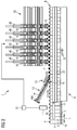
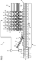
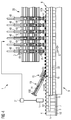
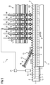
- Figures 1 to 5 show an applying unit 1 for applying lids 100 of opening devices 2 on packages 3, in particular packages 3 of food products pourable into a tube of packaging material.
- the packages 3 are produced upstream of the applying unit 1 by a packaging machine from a sheet packaging material comprising a base layer, e.g. formed by cardboard-like fibrous material or mineral-filled polypropylene material, and a number of layers of heat-seal plastic material, e.g. polyethylene film, covering both sides of the base layer.
- the packaging material also comprises a layer of gas- and light-barrier material, e.g.
- aluminium foil or ethyl vinyl alcohol (EVOH) which is superimposed on a layer of heat-seal plastic material, and is in turn covered with another layer of heat-seal plastic material forming the inner face of the packages 3 eventually contacting the food product.
- EVOH ethyl vinyl alcohol
- the packaging machine manufactures sealed packages 3 containing a pourable food product, such as UHT or pasteurised milk, fruit juice, wine, etc.
- a pourable food product such as UHT or pasteurised milk, fruit juice, wine, etc.
- the packaging machine could also manufacture sealed packages 3 containing a food product, which may be poured within the tube of packaging material during the step of manufacturing the packages 3 and subsequently hardens upon sealing of the packages 3.
- a food product is a portion of cheese, which is melted during the step of manufacturing the packages 3 and subsequently hardens upon sealing of the packages 3.
- each opening device 2 comprises a spout 4 that is moulded, in particular injection moulded, directly onto the packaging material when the packaging material has the shape of a web, or a sheet, i.e. before the packaging material is formed, filled and sealed so as to obtain the final packages 3.
- the spout 4 comprises a flange attached to the packaging material, a neck - particularly a threaded neck - protruding from a top wall of the packages 3 and defining a pouring opening, and a wall portion closing the pouring opening.
- the wall portion is removed from the neck through a pull element that may be pulled by a user when the packages 3 are opened for the first time.
- the opening device 2 may be moulded on the packaging material at a hole, punched in the packaging material in the filling machine.
- the opening device 2 may be moulded on the packaging material at a so-called “prelaminated” hole, i.e. a hole formed in the base layer of the packaging material and closed hermetically by other layers (at least the layers of thermoplastic material) of the packaging material.
- prelaminated hole i.e. a hole formed in the base layer of the packaging material and closed hermetically by other layers (at least the layers of thermoplastic material) of the packaging material.
- Each package 3 has, in the embodiment shown, a substantially parallelepiped body 5 and a slanted top wall 6, i.e. a top wall that is inclined with respect to a base wall 7 of the package 3.
- a slanted top wall 6 i.e. a top wall that is inclined with respect to a base wall 7 of the package 3.
- the top wall 6 is inclined with respect to a horizontal plane parallel to the bottom wall 7.
- each package has a substantially parallelepiped body 5 and a top wall substantially parallel to the bottom wall.
- the applying unit 1 may work with packages of different shapes.
- the applying unit 1 further comprises a conveying device 8 for conveying the packages 3 along a path Q.
- Path Q is rectilinear in the embodiment shown.
- the applying unit 1 also comprises a sequencing mechanism 18 interacting with the packages 3 travelling along path Q.
- the applying unit 1 further comprises a sensor 17 for generating a signal associated to the position of the packages 3, in particular the position of the spout 4 on which a corresponding lid 100 has to be applied.
- the conveying device 8 comprises a linear conveyor 9 that extends along path Q and cooperates with the bottom walls 7 of the packages 3.
- the linear conveyor comprises belt a 10 having an active branch, arranged in a substantially horizontal plane, which supports and advances the packages 3.
- the conveying device 8 further comprises a pair of endless belt conveyors 22 positioned on opposite lateral sides of the linear conveyor 9 and arranged to interact with respective opposite side walls 11 of the packages 3 that are carried by the linear conveyor 9.
- the applying unit 1 further comprises a capping device 12.
- the capping device 12 is arranged above the conveying device 8 and is intended to apply the lids 100 to the spouts 4, whilst the packages 3 are advanced by the conveying device 8.
- the capping device 12 comprises a plurality of applying devices 40 that move along path Q and apply the lids 100 to the spouts 4 of the opening devices 2.
- the capping device 12 further comprises a track arrangement 20 and a plurality of transfer arrangements 19 movable on the track arrangement 20, each transfer arrangement 19 being operatively connected to a corresponding applying device 40.
- the capping device 12 also comprises a control unit 21 which controls the transfer arrangements 19 on the basis of the signal generated by the sensor 17.
- the track arrangement 20 comprises a first track 23a and a second tack 23b.
- the track arrangement 20 may comprise only one track, or more than two tracks.
- Each transfer arrangement 19 comprises a first cart 25a a movable along the first track 23a and a second cart 25b movable along the second track 23b.
- each transfer arrangement 19 may comprise only one cart, or more than two carts, depending on the number of tracks of the corresponding track arrangement.
- the track arrangement 20 is substantially rectilinear and parallel to path Q.
- the transfer arrangements 19 are self-movable and move relative to the track arrangement 20 independently of each other.
- the track arrangement 20 houses a stator armature 24 formed by a plurality of individually-excitable solenoids (known per se), and the transfer arrangements 19 house respective permanent magnets (known per se) independently movable along the track arrangement 20 by individually controlling the solenoids by means of the control unit 21.
- individually-excitable solenoids are carried by the transfer arrangements and the permanent magnets are housed by the track arrangement.
- the capping device 12 further comprises a guide device 26 for guiding the transfer arrangements 19 along the track arrangement 20.
- the guide device 26 comprises a bar arrangement 27 and a plurality of slide arrangements 28 movable on the bar arrangement 27, each slide arrangement 28 being operatively connected to a corresponding applying device 40.
- the bar arrangement 27 comprises a first bar 29a and a second bar 29b.
- the bar arrangement 27 may comprise only one bar, or more than two bar.
- Each slide arrangement 28 comprises a first slide 30a movable along the first bar 29a and a second slide 30b movable along the second bar 29b.
- each slide arrangement 28 may comprise only one slide, or more than two slides, depending on the number of bars of the corresponding bar arrangement.
- the bar arrangement 27 is substantially rectilinear and parallel to path Q.
- the capping device 12 further comprises a delivery assembly 13 for feeding the lids 100 to the opening devices 2.
- the delivery assembly comprises a slide 14 and a feeding unit - not shown - that supplies the lids 100 to the slide 14.
- the slide 14 is inclined with respect to the linear conveyor 9, in particular with respect to the belt 10, in such a way that the distance between the slide 14 and the linear conveyor 9 decreases when moving along path Q.
- the slide 14 comprises, at an end 15 thereof closer to the linear conveyor 9, a dispensing opening 16.
- the dispensing opening is configured so as to loosely retain one lid 100.
- the lid 100 partially projects from the dispensing opening 16, but - at the same time - is prevented from falling down from the dispensing opening 16.
- the spout 4 of the opening device 2 interacts with the lid 100 retained by the dispensing opening 16 and removes the lid 100 from the dispensing opening 16. Therefore, downstream of the slide 14, the lid 100 rests on the spout 4, but it is not fully applied to the spout 4.
- Each transfer arrangement 19 comprises a supporting structure 31 connected to the first slide 30a and second slide 30b and to the first cart 25a and second cart 25b.
- the supporting structure 31 supports a corresponding applying device 40.
- Each applying device 40 comprises an applying head 41 movable with respect to the supporting structure 31 along an axis A, substantially perpendicular to path Q.
- axis A is substantially vertical.
- the applying head 41 is also rotatable with respect to the supporting structure 31 around axis A, according to direction R.
- the applying head 40 moves along axis A and rotates around axis A, according to direction R, so as to screw the lids 100 on the spouts 4.
- the sequencing mechanism 18 interacts with the packages 3, so as to:
- the sequencing mechanism 18 comprises a motor - not shown - and a couple belts 32 driven by the motor, arranged on opposite sides of the linear conveyor 9 and adapted to exert a given grip on the side walls 11 of the packages 3.
- applying unit 1 The operation of the applying unit 1 is described in the following of the present description with reference to one package 3, to the corresponding lid 100 and to the associated applying device 40.
- the package 3 is advanced along the conveying device 9 and, upon reaching the delivery assembly 13, the spout 4 removes a lid 100 from the dispensing opening 16.
- the sensor 17 generates a signal associated to the position of the package 3, and therefore of the lid 100.
- control unit 20 controls the transfer arrangement 19 so as to move the applying device 40 along a direction D, parallel to the advancing direction of the packages 3 along path Q.
- the applying device 40 moves, along direction D, together with the package 3, and the applying head 41 is translated along axis A and rotated around axis A so as to screw the lid 100 on the spout 4, whilst the package 3 is moved along the linear conveyor 9.
- the transfer arrangement 19 is synchronized with the package 3 and, therefore, the applying device 40 follows the package 3 along path Q.
- the transfer arrangement 19 (and therefore the applying device 40) is moved along a further direction E, opposite to direction D, with respect to the advancing direction of the packages 3 along path Q.
- the applying device 40 is so aligned - and subsequently interacts - with a new package 3, to apply a lid 100 to the spout of the new package 3.
- the transfer arrangement 19 (and the applying device 40) has, therefore, an indexing movement, i.e. reciprocates, along path Q.
- the capping device 12 comprises six applying devices 40. In this way, six lids 100 are applied to six packages 3 substantially at the same time.
- the sequencing mechanism 18 interacts with the packages 3 so as to form a queue of packages 3 substantially with no gap therebetween.
- the capping device 12 therefore, interacts with a group of twelve packages 3 in two consecutive steps.
- the six applying devices 40 apply six lids 100 to six packages 3, in particular on the first, third, fifth, seventh, ninth and eleventh package 3 of the group of packages 3.
- the six applying devices 40 are moved along the further direction E and are aligned with the remaining six packages 3 of the group and apply the lids 100 on such packages 3, in particular on the second, fourth, sixth, eighth, tenth and twelfth package 3 of the group of packages 3.
- the six applying devices 40 are moved along the further direction E and interact with a new group of packages 3.
- the six applying devices 40 interacts with a group of six consecutive packages 3 and apply the lids 100 to the packages 3 whilst the packages 3 move along path Q in the advancing direction. Subsequently the six applying devices 40 are moved along the further direction E and interact with a new group of six consecutive packages 3. This happens, in particular, with a queue of packages 3 substantially with no gap therebetween - if the length l of the packages 3 measured along path Q is greater than the minimum pitch between two consecutive applying devices 40 - or with a queue of packages 3 spaced by a gap along path Q.
- the track arrangement 20 is shaped as a loop.
- the track arrangement 20 is arranged above the conveying device 8 and in a plane parallel to path Q.
- the track arrangement 20 is arranged in a substantially vertical plane.
- the track arrangement 20 comprises a rectilinear active branch, a rectilinear return branch, a first curved branch and a second curved branch connecting opposite ends of the active branch and the return branch.
- the active branch is closer to the conveying device 8 than the return branch.
- the return branch is arranged above the active branch.
- the applying devices 40 apply the lids 100 to a group of packages 3 whilst the corresponding transfer arrangements 19 move along the active branch. Subsequently the transfer arrangement 19 are moved along the first curved branch, the return branch and the second curved branch so as to reach again the active branch and apply the lids 100 to a another group of packages 3.
- the speed of the transfer arrangements 19 along the active branch is the same as the speed of the packages (at least when the applying devices 40 apply the lids 100 to the packages 3).
- the speed of the transfer arrangements 19 along the first curved branch, the return branch and the second curved branch may be different - and, in particular, greater - than the speed of the transfer arrangements 19 along the active branch.
- the opening devices 2 comprise flip caps, rather than screw caps.
- the applying devices 40 are configured to push the lids 100 on the spout 4, instead of screwing the lids 100 as in the embodiment shown.
- the applying devices 40 may be equipped with different kinds of applying heads 41, such different kinds of applying heads 41 being able to apply different kinds of lids 100.
- the transfer arrangements 19 are self-movable and movable independently from each other along the track arrangement 20.
- each transfer arrangement 19 may move along the track arrangement 20 with a specific motion law.
- lids are applied by the applying heads 41 and not by belts which have to interact whit diametrically opposite portions of the lids in order to rotate the lids.
- each transfer arrangement 19 is controlled independently from the other transfer arrangements 19 by the control unit 21 on the basis of the signal generated by the control unit 21.
- the control unit 21 controls the motion law of the transfer arrangements 19 in such a way that each applying device 40 is synchronized with the corresponding package 3.
- the throughput of the applying unit 1 may be much greater than the one of the known applying units (in particular greater than 40000 packages/hour).
Claims (10)
- Unité d'application pour appliquer des couvercles (100) de dispositifs d'ouverture (2) à des becs verseurs (4) d'emballages (3), l'unité d'application comprenant un dispositif de transport (8) pour faire avancer lesdits emballages (3) le long d'un chemin (Q), une pluralité de dispositifs d'application (40) agencés pour appliquer lesdits couvercles (100) auxdits becs verseurs (4), lesdits dispositifs d'application (40) appliquant lesdits couvercles auxdits becs verseurs (4) pendant que lesdits emballages (3) sont avancés par ledit dispositif de transport (8), l'unité comprenant en outre une pluralité d'agencements de transfert (19), chaque agencement de transfert (19) supportant un dispositif d'application correspondant (40), dans laquelle ladite pluralité d'agencements de transfert (19) est mobile le long d'un agencement de piste (20), ledit dispositif d'application (8) est aligné avec ledit agencement de piste (20), lesdits agencements de transfert (19) sont automoteurs le long dudit agencement de piste (20) et sont mobiles indépendamment les uns des autres le long dudit agencement de piste (20).
- Unité d'application selon la revendication 1, et comprenant en outre un capteur (17) apte à générer un signal associé à la position desdits becs verseurs (4), et une unité de commande électronique (21) configurée de manière à recevoir, lors de l'utilisation, ledit signal et pour commander, lors de l'utilisation, le déplacement desdits agencements de transfert (19).
- Unité d'application selon la revendication 1 ou 2, dans laquelle ledit agencement de piste (20) contient une pluralité de solénoïdes excitables individuellement, et lesdits agencements de transfert (19) incorporent des aimants mobiles de façon indépendante le long dudit agencement de piste (20) en commandant individuellement lesdits solénoïdes, ou dans laquelle ledit agencement de piste (20) contient des aimants et lesdits agencements de transfert (19) incorporent une pluralité de solénoïdes excitables individuellement mobiles de façon indépendante le long dudit agencement de piste (20) en commandant individuellement lesdits solénoïdes.
- Unité d'application selon l'une quelconque des revendications 1 à 3, dans laquelle ledit agencement de piste (20) est un agencement de piste linéaire (20), et lesdites agencements de transfert (19) vont et viennent le long dudit agencement de piste (20).
- Unité d'application selon l'une quelconque des revendications 1 à 3, dans laquelle ledit agencement de piste (20) est un agencement de piste en forme de boucle.
- Unité d'application selon la revendication 5, dans laquelle lesdits agencements de transfert (19) supportent lesdits dispositifs d'application (40) de telle manière que lesdits dispositifs d'application (40) soient mobiles en direction et à l'écart dudit dispositif de transport (8).
- Unité d'application selon la revendication 6, dans laquelle lesdits agencements de transfert (19) supportent lesdits dispositifs d'application (40) de telle manière que lesdits dispositifs d'application (40) soient rotatifs autour d'un axe respectif (A) de ceux-ci.
- Unité d'application selon l'une quelconque des revendications précédentes, dans laquelle ledit agencement de piste (20) comprend une première piste (23a) et une seconde piste (23b), et chaque agencement de transfert (19) comprend un premier chariot (25a) mobile le long de ladite première piste (23a) et un second chariot (25b) mobile le long de ladite seconde piste (23b).
- Unité d'application selon l'une quelconque des revendications précédentes, et comprenant en outre un dispositif de guidage (26) pour guider lesdits agencements de transfert (19) le long dudit agencement de piste (20), ledit dispositif de guidage (26) comprenant un agencement de barre (27) et une pluralité d'agencements de coulisse (28), chaque agencement de coulisse (28) étant connecté à un agencement de transfert correspondant (19) et étant mobile sur ledit agencement de barre (27).
- Unité d'application selon la revendication 9, dans laquelle ledit agencement de barre (27) comprend une première barre (29a) et une seconde barre (29b), et chaque agencement de coulisse (28) comprend une première coulisse (30a) mobile le long de ladite première barre (29a) et une seconde coulisse (30b) mobile long de ladite seconde barre (29b).
Priority Applications (5)
| Application Number | Priority Date | Filing Date | Title |
|---|---|---|---|
| EP14163507.8A EP2927132B1 (fr) | 2014-04-04 | 2014-04-04 | Unité pour l'application de couvercles de dispositifs d'ouverture |
| PCT/EP2015/053469 WO2015149988A1 (fr) | 2014-04-04 | 2015-02-19 | Unité pour l'application de couvercles de dispositifs d'ouverture |
| CN201580004979.2A CN105916770B (zh) | 2014-04-04 | 2015-02-19 | 用于施加开口装置的盖的单元 |
| US15/301,877 US10654698B2 (en) | 2014-04-04 | 2015-02-19 | Unit for the application of lids of opening devices |
| JP2016560775A JP6473169B2 (ja) | 2014-04-04 | 2015-02-19 | オープニングデバイスの蓋を取り付けるためのユニット |
Applications Claiming Priority (1)
| Application Number | Priority Date | Filing Date | Title |
|---|---|---|---|
| EP14163507.8A EP2927132B1 (fr) | 2014-04-04 | 2014-04-04 | Unité pour l'application de couvercles de dispositifs d'ouverture |
Publications (2)
| Publication Number | Publication Date |
|---|---|
| EP2927132A1 EP2927132A1 (fr) | 2015-10-07 |
| EP2927132B1 true EP2927132B1 (fr) | 2016-09-14 |
Family
ID=50479024
Family Applications (1)
| Application Number | Title | Priority Date | Filing Date |
|---|---|---|---|
| EP14163507.8A Active EP2927132B1 (fr) | 2014-04-04 | 2014-04-04 | Unité pour l'application de couvercles de dispositifs d'ouverture |
Country Status (5)
| Country | Link |
|---|---|
| US (1) | US10654698B2 (fr) |
| EP (1) | EP2927132B1 (fr) |
| JP (1) | JP6473169B2 (fr) |
| CN (1) | CN105916770B (fr) |
| WO (1) | WO2015149988A1 (fr) |
Families Citing this family (8)
| Publication number | Priority date | Publication date | Assignee | Title |
|---|---|---|---|---|
| EP3205589B1 (fr) * | 2016-02-12 | 2019-04-03 | Tetra Laval Holdings & Finance S.A. | Unité de distribution pour l'alimentation de couvercles sur des cols de récipients |
| MX2016006922A (es) * | 2016-05-27 | 2017-11-27 | Pack System S A De C V | Sistema de taponado lineal de multiples cabezas de traccion independiente. |
| CN107601396A (zh) * | 2017-08-30 | 2018-01-19 | 苏州首达机械有限公司 | 一种应用于灌装行业的放盖机构 |
| ES2890431T3 (es) * | 2018-11-23 | 2022-01-19 | Tetra Laval Holdings & Finance | Aparato de capsulado para un sistema de producción de productos alimentarios envasados |
| SE544358C2 (en) | 2019-07-02 | 2022-04-19 | A & R Carton Lund Ab | Method of producing a packaging container and a packaging container |
| CN111003677A (zh) * | 2019-12-11 | 2020-04-14 | 佛山市金银河智能装备股份有限公司 | 一种铝瓶分装机及其分装方法 |
| CN115315393A (zh) * | 2020-03-20 | 2022-11-08 | 利乐拉瓦尔集团及财务有限公司 | 用于控制可沿环形轨道移动的多个推车的方法 |
| CN111977585A (zh) * | 2020-08-13 | 2020-11-24 | 黄松 | 一种自动化瓶盖拧紧机 |
Family Cites Families (13)
| Publication number | Priority date | Publication date | Assignee | Title |
|---|---|---|---|---|
| US3852941A (en) * | 1973-08-20 | 1974-12-10 | Pennwalt Corp | Vial capping apparatus |
| JPH0487911A (ja) | 1990-07-19 | 1992-03-19 | Ougi Kikai Seisakusho:Kk | 自動ラインキャッパ |
| US5809742A (en) * | 1997-03-04 | 1998-09-22 | Toyo Seikan Kaisha, Ltd. | Capping apparatus |
| JP4081892B2 (ja) | 1998-11-25 | 2008-04-30 | 澁谷工業株式会社 | キャッパ |
| CN2474471Y (zh) * | 2001-01-18 | 2002-01-30 | 王彦军 | 塑料瓶与塑料盖愈合一体封口机 |
| EP1462370B2 (fr) * | 2003-03-28 | 2011-09-07 | Tetra Laval Holdings & Finance SA | Unité d'application d'éléments d'ouverture à des emballages de produits alimentaires liquides |
| PL1813533T3 (pl) | 2006-01-31 | 2009-04-30 | Tetra Laval Holdings & Finance | Modularna jednostka do nakładania urządzeń otwierających na opakowania płynnych produktów spożywczych |
| DE602006009612D1 (de) | 2006-01-31 | 2009-11-19 | Tetra Laval Holdings & Finance | Einrichtung zum Anbringen von Öffnungsvorrichtungen an Verpackungen für flüssige Nahrungsmittel |
| IT1391875B1 (it) | 2008-11-14 | 2012-01-27 | Tetra Laval Holdings & Finance | Dispositivo pressatore atto ad esercitare una pressione su un dispositivo di apertura applicato su una confezione contenente un prodotto alimentare versabile in un tubo di materiale di confezionamento |
| ITTO20080915A1 (it) * | 2008-12-09 | 2010-06-10 | Tetra Laval Holdings & Finance | Unita' per l'applicazione di dispositivi di apertura su confezioni di prodotti alimentari versabili in un tubo di materiale di confezionamento |
| JP5383546B2 (ja) * | 2010-02-22 | 2014-01-08 | 花王株式会社 | キャップ締付装置 |
| DE102011010842A1 (de) | 2011-02-10 | 2012-02-02 | Daimler Ag | Verdeck für einen offenen Personenkraftwagen |
| DE102011108428A1 (de) * | 2011-07-26 | 2013-01-31 | Khs Gmbh | Vorrichtung zum Verschließen von Behältern |
-
2014
- 2014-04-04 EP EP14163507.8A patent/EP2927132B1/fr active Active
-
2015
- 2015-02-19 WO PCT/EP2015/053469 patent/WO2015149988A1/fr active Application Filing
- 2015-02-19 JP JP2016560775A patent/JP6473169B2/ja not_active Expired - Fee Related
- 2015-02-19 CN CN201580004979.2A patent/CN105916770B/zh active Active
- 2015-02-19 US US15/301,877 patent/US10654698B2/en active Active
Also Published As
| Publication number | Publication date |
|---|---|
| WO2015149988A1 (fr) | 2015-10-08 |
| EP2927132A1 (fr) | 2015-10-07 |
| JP2017509558A (ja) | 2017-04-06 |
| CN105916770A (zh) | 2016-08-31 |
| CN105916770B (zh) | 2019-08-13 |
| US10654698B2 (en) | 2020-05-19 |
| JP6473169B2 (ja) | 2019-02-20 |
| US20170029257A1 (en) | 2017-02-02 |
Similar Documents
| Publication | Publication Date | Title |
|---|---|---|
| EP2927132B1 (fr) | Unité pour l'application de couvercles de dispositifs d'ouverture | |
| US9878815B2 (en) | Unit for the application of opening devices on sealed packages of food products | |
| EP1798149B1 (fr) | Procédé et dispositif pour appliquer une substance adhesive sur des becs verseurs pour les encoller sur des emballages contenant des produits alimentaires versables | |
| CN107922060B (zh) | 一种用于将盖施加于容器上的施加单元 | |
| US9096337B2 (en) | Gluing unit for applying adhesive to a succession of opening devices for gluing to sealed packages of food products pourable into a tube of packaging material | |
| CN107922061B (zh) | 一种用于封盖容器的设备 | |
| EP2960188B1 (fr) | Unité de convoyage permettant d'acheminer des paquets et procédé permettant d'acheminer des paquets | |
| US9187199B2 (en) | Unit for the application of opening devices on packages of food products pourable into a tube of packaging material | |
| EP2376331B1 (fr) | Dispositif presseur exerçant une pression sur un dispositif d'ouverture fixé à un emballage de produit alimentaire versable dans un tube de matériau d'emballage | |
| CN107921715B (zh) | 一种焊头 | |
| CN107922062B (zh) | 用于将盖施加于容器上的方法和施加头 | |
| EP2955118B1 (fr) | Unité d'alimentation pour alimenter des emballages scellés de produits alimentaires versables | |
| US11186392B2 (en) | Distribution unit for feeding lids to necks of containers | |
| EP4289587A1 (fr) | Outil de moulage, appareil de moulage comprenant un outil de moulage et machine d'emballage comprenant un appareil de moulage | |
| EP4289588A1 (fr) | Outil de moulage, appareil de moulage comprenant un outil de moulage et machine d'emballage comprenant un appareil de moulage |
Legal Events
| Date | Code | Title | Description |
|---|---|---|---|
| PUAI | Public reference made under article 153(3) epc to a published international application that has entered the european phase |
Free format text: ORIGINAL CODE: 0009012 |
|
| AK | Designated contracting states |
Kind code of ref document: A1 Designated state(s): AL AT BE BG CH CY CZ DE DK EE ES FI FR GB GR HR HU IE IS IT LI LT LU LV MC MK MT NL NO PL PT RO RS SE SI SK SM TR |
|
| AX | Request for extension of the european patent |
Extension state: BA ME |
|
| 17P | Request for examination filed |
Effective date: 20160407 |
|
| RBV | Designated contracting states (corrected) |
Designated state(s): AL AT BE BG CH CY CZ DE DK EE ES FI FR GB GR HR HU IE IS IT LI LT LU LV MC MK MT NL NO PL PT RO RS SE SI SK SM TR |
|
| GRAP | Despatch of communication of intention to grant a patent |
Free format text: ORIGINAL CODE: EPIDOSNIGR1 |
|
| RIC1 | Information provided on ipc code assigned before grant |
Ipc: H02K 41/03 20060101ALN20160506BHEP Ipc: B65B 59/02 20060101ALI20160506BHEP Ipc: B65B 61/18 20060101ALN20160506BHEP Ipc: B67B 3/20 20060101ALI20160506BHEP Ipc: B65B 7/28 20060101AFI20160506BHEP Ipc: B65B 57/16 20060101ALI20160506BHEP |
|
| INTG | Intention to grant announced |
Effective date: 20160601 |
|
| GRAS | Grant fee paid |
Free format text: ORIGINAL CODE: EPIDOSNIGR3 |
|
| GRAA | (expected) grant |
Free format text: ORIGINAL CODE: 0009210 |
|
| AK | Designated contracting states |
Kind code of ref document: B1 Designated state(s): AL AT BE BG CH CY CZ DE DK EE ES FI FR GB GR HR HU IE IS IT LI LT LU LV MC MK MT NL NO PL PT RO RS SE SI SK SM TR |
|
| REG | Reference to a national code |
Ref country code: GB Ref legal event code: FG4D |
|
| REG | Reference to a national code |
Ref country code: CH Ref legal event code: EP |
|
| REG | Reference to a national code |
Ref country code: IE Ref legal event code: FG4D |
|
| REG | Reference to a national code |
Ref country code: AT Ref legal event code: REF Ref document number: 828673 Country of ref document: AT Kind code of ref document: T Effective date: 20161015 |
|
| REG | Reference to a national code |
Ref country code: DE Ref legal event code: R096 Ref document number: 602014003572 Country of ref document: DE |
|
| REG | Reference to a national code |
Ref country code: LT Ref legal event code: MG4D |
|
| REG | Reference to a national code |
Ref country code: NL Ref legal event code: MP Effective date: 20160914 |
|
| PG25 | Lapsed in a contracting state [announced via postgrant information from national office to epo] |
Ref country code: LT Free format text: LAPSE BECAUSE OF FAILURE TO SUBMIT A TRANSLATION OF THE DESCRIPTION OR TO PAY THE FEE WITHIN THE PRESCRIBED TIME-LIMIT Effective date: 20160914 Ref country code: FI Free format text: LAPSE BECAUSE OF FAILURE TO SUBMIT A TRANSLATION OF THE DESCRIPTION OR TO PAY THE FEE WITHIN THE PRESCRIBED TIME-LIMIT Effective date: 20160914 Ref country code: RS Free format text: LAPSE BECAUSE OF FAILURE TO SUBMIT A TRANSLATION OF THE DESCRIPTION OR TO PAY THE FEE WITHIN THE PRESCRIBED TIME-LIMIT Effective date: 20160914 Ref country code: HR Free format text: LAPSE BECAUSE OF FAILURE TO SUBMIT A TRANSLATION OF THE DESCRIPTION OR TO PAY THE FEE WITHIN THE PRESCRIBED TIME-LIMIT Effective date: 20160914 Ref country code: NO Free format text: LAPSE BECAUSE OF FAILURE TO SUBMIT A TRANSLATION OF THE DESCRIPTION OR TO PAY THE FEE WITHIN THE PRESCRIBED TIME-LIMIT Effective date: 20161214 |
|
| REG | Reference to a national code |
Ref country code: AT Ref legal event code: MK05 Ref document number: 828673 Country of ref document: AT Kind code of ref document: T Effective date: 20160914 |
|
| PG25 | Lapsed in a contracting state [announced via postgrant information from national office to epo] |
Ref country code: NL Free format text: LAPSE BECAUSE OF FAILURE TO SUBMIT A TRANSLATION OF THE DESCRIPTION OR TO PAY THE FEE WITHIN THE PRESCRIBED TIME-LIMIT Effective date: 20160914 Ref country code: GR Free format text: LAPSE BECAUSE OF FAILURE TO SUBMIT A TRANSLATION OF THE DESCRIPTION OR TO PAY THE FEE WITHIN THE PRESCRIBED TIME-LIMIT Effective date: 20161215 Ref country code: SE Free format text: LAPSE BECAUSE OF FAILURE TO SUBMIT A TRANSLATION OF THE DESCRIPTION OR TO PAY THE FEE WITHIN THE PRESCRIBED TIME-LIMIT Effective date: 20160914 Ref country code: LV Free format text: LAPSE BECAUSE OF FAILURE TO SUBMIT A TRANSLATION OF THE DESCRIPTION OR TO PAY THE FEE WITHIN THE PRESCRIBED TIME-LIMIT Effective date: 20160914 |
|
| REG | Reference to a national code |
Ref country code: FR Ref legal event code: PLFP Year of fee payment: 4 |
|
| PG25 | Lapsed in a contracting state [announced via postgrant information from national office to epo] |
Ref country code: EE Free format text: LAPSE BECAUSE OF FAILURE TO SUBMIT A TRANSLATION OF THE DESCRIPTION OR TO PAY THE FEE WITHIN THE PRESCRIBED TIME-LIMIT Effective date: 20160914 Ref country code: RO Free format text: LAPSE BECAUSE OF FAILURE TO SUBMIT A TRANSLATION OF THE DESCRIPTION OR TO PAY THE FEE WITHIN THE PRESCRIBED TIME-LIMIT Effective date: 20160914 |
|
| PG25 | Lapsed in a contracting state [announced via postgrant information from national office to epo] |
Ref country code: BE Free format text: LAPSE BECAUSE OF FAILURE TO SUBMIT A TRANSLATION OF THE DESCRIPTION OR TO PAY THE FEE WITHIN THE PRESCRIBED TIME-LIMIT Effective date: 20160914 Ref country code: BG Free format text: LAPSE BECAUSE OF FAILURE TO SUBMIT A TRANSLATION OF THE DESCRIPTION OR TO PAY THE FEE WITHIN THE PRESCRIBED TIME-LIMIT Effective date: 20161214 Ref country code: ES Free format text: LAPSE BECAUSE OF FAILURE TO SUBMIT A TRANSLATION OF THE DESCRIPTION OR TO PAY THE FEE WITHIN THE PRESCRIBED TIME-LIMIT Effective date: 20160914 Ref country code: SK Free format text: LAPSE BECAUSE OF FAILURE TO SUBMIT A TRANSLATION OF THE DESCRIPTION OR TO PAY THE FEE WITHIN THE PRESCRIBED TIME-LIMIT Effective date: 20160914 Ref country code: CZ Free format text: LAPSE BECAUSE OF FAILURE TO SUBMIT A TRANSLATION OF THE DESCRIPTION OR TO PAY THE FEE WITHIN THE PRESCRIBED TIME-LIMIT Effective date: 20160914 Ref country code: IS Free format text: LAPSE BECAUSE OF FAILURE TO SUBMIT A TRANSLATION OF THE DESCRIPTION OR TO PAY THE FEE WITHIN THE PRESCRIBED TIME-LIMIT Effective date: 20170114 Ref country code: PL Free format text: LAPSE BECAUSE OF FAILURE TO SUBMIT A TRANSLATION OF THE DESCRIPTION OR TO PAY THE FEE WITHIN THE PRESCRIBED TIME-LIMIT Effective date: 20160914 Ref country code: SM Free format text: LAPSE BECAUSE OF FAILURE TO SUBMIT A TRANSLATION OF THE DESCRIPTION OR TO PAY THE FEE WITHIN THE PRESCRIBED TIME-LIMIT Effective date: 20160914 Ref country code: AT Free format text: LAPSE BECAUSE OF FAILURE TO SUBMIT A TRANSLATION OF THE DESCRIPTION OR TO PAY THE FEE WITHIN THE PRESCRIBED TIME-LIMIT Effective date: 20160914 Ref country code: PT Free format text: LAPSE BECAUSE OF FAILURE TO SUBMIT A TRANSLATION OF THE DESCRIPTION OR TO PAY THE FEE WITHIN THE PRESCRIBED TIME-LIMIT Effective date: 20170116 |
|
| REG | Reference to a national code |
Ref country code: DE Ref legal event code: R097 Ref document number: 602014003572 Country of ref document: DE |
|
| PLBE | No opposition filed within time limit |
Free format text: ORIGINAL CODE: 0009261 |
|
| STAA | Information on the status of an ep patent application or granted ep patent |
Free format text: STATUS: NO OPPOSITION FILED WITHIN TIME LIMIT |
|
| PG25 | Lapsed in a contracting state [announced via postgrant information from national office to epo] |
Ref country code: DK Free format text: LAPSE BECAUSE OF FAILURE TO SUBMIT A TRANSLATION OF THE DESCRIPTION OR TO PAY THE FEE WITHIN THE PRESCRIBED TIME-LIMIT Effective date: 20160914 |
|
| 26N | No opposition filed |
Effective date: 20170615 |
|
| PG25 | Lapsed in a contracting state [announced via postgrant information from national office to epo] |
Ref country code: SI Free format text: LAPSE BECAUSE OF FAILURE TO SUBMIT A TRANSLATION OF THE DESCRIPTION OR TO PAY THE FEE WITHIN THE PRESCRIBED TIME-LIMIT Effective date: 20160914 |
|
| REG | Reference to a national code |
Ref country code: CH Ref legal event code: PL |
|
| REG | Reference to a national code |
Ref country code: IE Ref legal event code: MM4A |
|
| PG25 | Lapsed in a contracting state [announced via postgrant information from national office to epo] |
Ref country code: MC Free format text: LAPSE BECAUSE OF FAILURE TO SUBMIT A TRANSLATION OF THE DESCRIPTION OR TO PAY THE FEE WITHIN THE PRESCRIBED TIME-LIMIT Effective date: 20160914 |
|
| PG25 | Lapsed in a contracting state [announced via postgrant information from national office to epo] |
Ref country code: LI Free format text: LAPSE BECAUSE OF NON-PAYMENT OF DUE FEES Effective date: 20170430 Ref country code: LU Free format text: LAPSE BECAUSE OF NON-PAYMENT OF DUE FEES Effective date: 20170404 Ref country code: CH Free format text: LAPSE BECAUSE OF NON-PAYMENT OF DUE FEES Effective date: 20170430 |
|
| REG | Reference to a national code |
Ref country code: FR Ref legal event code: PLFP Year of fee payment: 5 |
|
| PG25 | Lapsed in a contracting state [announced via postgrant information from national office to epo] |
Ref country code: IE Free format text: LAPSE BECAUSE OF NON-PAYMENT OF DUE FEES Effective date: 20170404 |
|
| PGFP | Annual fee paid to national office [announced via postgrant information from national office to epo] |
Ref country code: FR Payment date: 20180315 Year of fee payment: 5 |
|
| PG25 | Lapsed in a contracting state [announced via postgrant information from national office to epo] |
Ref country code: MT Free format text: LAPSE BECAUSE OF NON-PAYMENT OF DUE FEES Effective date: 20170404 |
|
| PG25 | Lapsed in a contracting state [announced via postgrant information from national office to epo] |
Ref country code: AL Free format text: LAPSE BECAUSE OF FAILURE TO SUBMIT A TRANSLATION OF THE DESCRIPTION OR TO PAY THE FEE WITHIN THE PRESCRIBED TIME-LIMIT Effective date: 20160914 |
|
| GBPC | Gb: european patent ceased through non-payment of renewal fee |
Effective date: 20180404 |
|
| PG25 | Lapsed in a contracting state [announced via postgrant information from national office to epo] |
Ref country code: GB Free format text: LAPSE BECAUSE OF NON-PAYMENT OF DUE FEES Effective date: 20180404 |
|
| PG25 | Lapsed in a contracting state [announced via postgrant information from national office to epo] |
Ref country code: HU Free format text: LAPSE BECAUSE OF FAILURE TO SUBMIT A TRANSLATION OF THE DESCRIPTION OR TO PAY THE FEE WITHIN THE PRESCRIBED TIME-LIMIT; INVALID AB INITIO Effective date: 20140404 |
|
| PG25 | Lapsed in a contracting state [announced via postgrant information from national office to epo] |
Ref country code: CY Free format text: LAPSE BECAUSE OF FAILURE TO SUBMIT A TRANSLATION OF THE DESCRIPTION OR TO PAY THE FEE WITHIN THE PRESCRIBED TIME-LIMIT Effective date: 20160914 |
|
| PG25 | Lapsed in a contracting state [announced via postgrant information from national office to epo] |
Ref country code: MK Free format text: LAPSE BECAUSE OF FAILURE TO SUBMIT A TRANSLATION OF THE DESCRIPTION OR TO PAY THE FEE WITHIN THE PRESCRIBED TIME-LIMIT Effective date: 20160914 |
|
| PG25 | Lapsed in a contracting state [announced via postgrant information from national office to epo] |
Ref country code: FR Free format text: LAPSE BECAUSE OF NON-PAYMENT OF DUE FEES Effective date: 20190430 |
|
| PG25 | Lapsed in a contracting state [announced via postgrant information from national office to epo] |
Ref country code: TR Free format text: LAPSE BECAUSE OF FAILURE TO SUBMIT A TRANSLATION OF THE DESCRIPTION OR TO PAY THE FEE WITHIN THE PRESCRIBED TIME-LIMIT Effective date: 20160914 |
|
| PGFP | Annual fee paid to national office [announced via postgrant information from national office to epo] |
Ref country code: IT Payment date: 20220421 Year of fee payment: 9 Ref country code: DE Payment date: 20220527 Year of fee payment: 9 |
|
| REG | Reference to a national code |
Ref country code: DE Ref legal event code: R119 Ref document number: 602014003572 Country of ref document: DE |
|
| PG25 | Lapsed in a contracting state [announced via postgrant information from national office to epo] |
Ref country code: DE Free format text: LAPSE BECAUSE OF NON-PAYMENT OF DUE FEES Effective date: 20231103 |