EP2927124B1 - Dispositif diviseur pliant destiné à une cabine d'aéronef - Google Patents
Dispositif diviseur pliant destiné à une cabine d'aéronef Download PDFInfo
- Publication number
- EP2927124B1 EP2927124B1 EP14163607.6A EP14163607A EP2927124B1 EP 2927124 B1 EP2927124 B1 EP 2927124B1 EP 14163607 A EP14163607 A EP 14163607A EP 2927124 B1 EP2927124 B1 EP 2927124B1
- Authority
- EP
- European Patent Office
- Prior art keywords
- bar elements
- stable state
- bar
- state
- divider device
- Prior art date
- Legal status (The legal status is an assumption and is not a legal conclusion. Google has not performed a legal analysis and makes no representation as to the accuracy of the status listed.)
- Active
Links
- 239000000463 material Substances 0.000 claims description 11
- 239000012781 shape memory material Substances 0.000 claims description 8
- 229910000639 Spring steel Inorganic materials 0.000 claims description 3
- 230000001419 dependent effect Effects 0.000 claims 1
- 238000005452 bending Methods 0.000 description 4
- 238000012216 screening Methods 0.000 description 4
- 230000009466 transformation Effects 0.000 description 4
- 230000002950 deficient Effects 0.000 description 1
- 238000004519 manufacturing process Methods 0.000 description 1
- 238000005192 partition Methods 0.000 description 1
- 238000000926 separation method Methods 0.000 description 1
Images


Classifications
-
- B—PERFORMING OPERATIONS; TRANSPORTING
- B64—AIRCRAFT; AVIATION; COSMONAUTICS
- B64D—EQUIPMENT FOR FITTING IN OR TO AIRCRAFT; FLIGHT SUITS; PARACHUTES; ARRANGEMENT OR MOUNTING OF POWER PLANTS OR PROPULSION TRANSMISSIONS IN AIRCRAFT
- B64D11/00—Passenger or crew accommodation; Flight-deck installations not otherwise provided for
- B64D11/0023—Movable or removable cabin dividers, e.g. for class separation
Definitions
- the present invention relates to a divider device for an aircraft cabin.
- Aircraft cabin arrangements usually comprise a plurality of seat rows which are arranged perpendicularly to a longitudinal axis of the cabin and in parallel one after another. Further, the cabin arrangement comprises different sections such as a business class and an economy class, and it is desirable to provide elements to visually separate the different sections from each other to prevent passengers from looking from one section to the other.
- a divider assembly comprising separate elements slidably supported in a guide rail extending perpendicularly to the longitudinal axis of the cabin along the ceiling portion.
- US 2012/0043028 discloses a hanging partition or divider element comprising a plurality of rectilinear bar elements or pleats. These pleats are pivotably coupled along parallel vertical lines so that adjacent pleats can be folded on top of each other and the entire divider element may assume a collapsed or extended state. Furthermore, in the top portion of the pleats magnet elements are arranged so that adjacent pleats are kept on top of each other when the divider element is in the collapsed state.
- a divider device for an aircraft cabin comprising a plurality of elongate bar elements, wherein each bar element is planar and flexible so that it may assume a linear state in which it extends rectilinearly along a longitudinal axis parallel to a plane, wherein each bar element has a first stable state in which it is curved, so that it deforms into its first stable state when being bent out of the linear state towards the first stable state to a predetermined extent, wherein the bar elements are arranged side-by-side and adjacent bar elements are pivotably interconnected with each other, so that when the bar elements are in the linear state, their longitudinal axes extend in parallel, and wherein each pair of first and second adjacent bar elements are designed such that when the first and the second bar elements are in the linear state and extend in a common plane, in the first stable state of the first bar element one end thereof is positioned on a first side of the plane whereas in the first stable state of the second bar element its end corresponding to the end of the first bar element is located on
- the divider device comprises a plurality of bar elements which are configured such that they have at least a first stable state in which the bar elements are curved, in particular S-shaped rather than extending rectilinearly, i.e. along a straight line, in a plane.
- the bar elements When these bar elements are bent from a linear state in which they have a rectilinear shape, towards the first stable state to a predetermined extent, the bar elements will automatically fully transform into the curved shape of the first stable state.
- the bar elements will directly transform their shape to the shape of the first stable state when the bar elements are not fixed in the linear state.
- Such a configuration can easily be achieved by using a flexible material for the bar elements such as spring steel, wherein the respective bar elements have been rolled such that they have a curved shape when no force is applied to the bar elements. Then, this curved shape corresponds to the first stable state into which the bar elements return when they are released after being bent into a shape where they extend rectilinearly in a plane. In such a case the bending from the linear state towards the first stable state occurs automatically, when the bar elements are no longer fixed and released from the linear state.
- a flexible material for the bar elements such as spring steel
- such bar elements are arranged side-by-side and are pivotably connected with each other wherein for each pair of adjacent bar elements the configuration is such that when both of these bar elements are in the linear shape and arranged in a common plane, in the first stable state an end of the first bar element would be located on one side of that plane whereas the corresponding end of the second bar element of that pair would be located on the other side of the plane.
- adjacent bar elements tend to bend to opposite sides of a plane when each of the bar elements of the device is entirely positioned in the common plane.
- the divider device of the present invention is folded from a straight vertical position into a stack, this stack will automatically assume a curved shape and remains in the folded state unless an external force is applied which bends the entire stack into a linear shape.
- the divider device is easy to handle, since the cabin crew has only to the bend the stack of interconnected bar elements into a linear shape to obtain the expanded vertical position of the divider in which it is effective as screening element.
- it is only required to fold the bars on top of each other towards the support element of the divider device such as the respective hatrack portion.
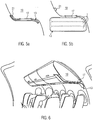
- the shape of the first stable state of the bar elements corresponds to the shape of the cross section of the hatrack.
- an S-shape is preferred. In this case the entire stack of bar elements follows the shape of the hatrack when the divider device is in the collapsed state.
- the bar elements are configured such that the linear state of the bar elements forms a second stable state so that when one of the bar elements is bent out of the linear state to an extent smaller than the predetermined extent, it returns back to the linear state.
- This has the advantage, that also the flat vertical configuration of the divider device, i.e. the expanded state, is a stable position of the device and an external force is required to bring the bar elements into the first stable state in which they are curved.
- the divider device comprises bar elements having first and second planar members which are arranged on top of each other. This allows to easily obtain first and second stable states of the entire bar elements.
- the first planar member is configured such that it defines the first stable state whereas the second planar member is in a stable state when the entire bar element has a flat rectilinear shape.
- first and second planar members have stable states to which they return when being bent out of its respective stable state to a limited extent. Further, the first planar member is in its stable state when the entire bar element is in the first stable state and the second planar member is in its stable state when the bar element is in the second stable state.
- the divider device comprises a flexible web-shaped cover material which encloses the bar elements.
- the cover material can form the hinge portions which interconnect adjacent bar elements and allows a pivoting movement between adjacent bar elements.
- the cover material can be adapted to form a projection screen or to give the entire divider device the desired appearance.
- the cover material may form pockets which extend in parallel to each other wherein the bar elements are received in the pockets.
- Such a configuration is easy to manufacture and assembly and allows to change single bar elements which are defective, in a simple manner.
- the divider device comprises a support element, which may be formed as a portion of the aircraft cabin ceiling or a hatrack portion, and one of the plurality of bar elements is pivotably connected to the support element.
- the support element comprises a magnet element that is arranged adjacent to one end of the bar elements and applies an attracting force to the ends of the bar elements. This ensures that in the collapsed state of the divider device the stack of bar elements is kept in the folded position by an additional force.
- the bar elements are formed of shape-memory material, wherein the first stable state of the bar elements corresponds to a least one permanent form of the bar elements.
- the first stable state of the bar elements corresponds to a least one permanent form of the bar elements.
- first and second planar members are formed of shape memory material wherein in the first stable state the first planar member is in a permanent form and wherein in the second stable state the second planar element is in a permanent form.
- a stimulus such as heat or an electric pulse is provided to the first planar members of the bar elements. This results in a force which bends the bar elements towards the curved shape corresponding to the first stable position.
- a stimulus is provided to the second planar members so that the bar elements are transformed into the second stable state corresponding to a linear shape.
- the device will automatically unfold.
- the preferred embodiment of a divider device according to the present invention as shown in the drawing comprises three planar elongate bar elements 1 which are flexible and may assume a linear state which is shown in Fig. 1 .
- the bar elements 1 In the linear state the bar elements 1 extend rectilinearly in a plane, i.e. the direction of extension of the bar elements 1 follows a straight line and is not curved.
- each bar element 1 comprises first and second planar elements 3, 5 which are arranged in parallel and on top of each other and are formed of spring steel.
- the bar elements 1 are configured such that they have first and second stable states as will be discussed in the following.
- the first planar member 3 is shown in two different states.
- the first planar member 3 has a stable state (shown in Part b) of Fig. 2 ) to which it returns when being bent out of this stable state to a limited extent.
- the first planar member 3 has a curved shape, i.e. is S-shaped, and does not extend in a plane compared to the linear state shown in the Part a) of Fig. 2 .
- the first planar member 3 is not actively maintained in the linear shape shown in Part a) of Fig. 2 , it immediately returns to the curved stable state of Part b).
- Fig. 2 shows the entire bar element 1 comprising the planar members 3, 5 in the first stable state (Part d)) and the second stable state (Part c)), the latter being defined by the second planar member 5.
- the second planar member 5 has a rectilinear shape, i.e. extends along a straight line, it is in its stable state to which it returns when being bent out of this state to a limited extent.
- first planar member 3 is initially rolled such that is has the shape shown in Part b) of Fig. 2
- second planar member 5 was originally formed to a shape shown in Part c) of Fig. 2 .
- the bar elements 1 In the first stable state of the bar elements 1, they have a curved shape as shown in Part d) of Fig. 2 , and when the entire bar elements 1 are bent out of this shape to a limited extent far away from the linear state shown in Part c) of Fig. 2 , the bar elements 1 will return to the curved shape and the first stable state, respectively, as the first planar member 3 provides for a corresponding force or bias.
- the bar elements 1 have a second stable state shown in Part c) of Fig. 2 which corresponds to a linear shape so that the bar elements 1 extend along a straight line in a plane.
- the linear shape of the bar elements 1 constitutes a stable state, the bar elements 1 will return to the linear shape, when slightly being bent due to a force generated by the second planar member 5.
- the bar elements 1 have the tendency to maintain its linear shape once being brought into.
- the bar elements 1 when the entire bar elements 1 are actively bent to a predetermined extent out of the linear shape towards the curved shape defining the first stable state by applying an external force, the bar elements 1 will automatically transform into the curved shape due to the force created by the first planar member 3.
- the first planar member 3 is in its stable state when the entire bar element 1 is in the first stable state
- the second planar member 5 is in its stable state when the bar element 1 is in the second stable state.
- the bar elements 1 are arranged side-by-side, and adjacent bar elements 1 are pivotably interconnected with each other, so that when the bar elements 1 are in the linear state or second stable state, their longitudinal axes extend in parallel.
- each pair of first and second adjacent bar elements 1', 1" are designed such that when the first and the second bar elements 1', 1" are in the linear state or second stable state so that they extend in a common plane 7, in the first stable state of the first bar element 1' one end 9' thereof will be positioned on a first side of the plane 7 as indicated by the arrow 11' extending from the end 9' of the first bar element 1'.
- the first stable state of the second bar element 1" its end 9" corresponding to the end 9' of the first bar element 1' will be located on a second side of the plane 7 opposite to the first side which is shown by the arrow 11" starting from the respective end 9" of the second bar element 1".
- the bar elements 1 are arranged in an alternating manner so that in the first stable state distal ends 9', 9" of adjacent bar elements 1', 1" are arranged on opposite sides of the plane 7 defined by the unfolded divider element. This means that adjacent bar elements 1', 1" tend to bend to opposite sides of the plane 7 when each of the bar elements 1 of the device is entirely positioned in that common plane 7.
- the divider device comprises a receptacle element 13 formed of flexible web-shaped material, and the receptacle element 13 is provided with elongate pockets 15 for receiving the bar elements 1 in a side-by-side configuration so that when the bar elements 1 are in the linear state, the longitudinal axes of the bar elements 1 are arranged in parallel.
- the material of the receptacle element 13 can be chosen such that the divider device may also be effective as a projection screen and/or symbols may be printed on the receptacle element 13.
- adjacent bar elements 1 are pivotably interconnected.
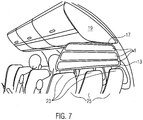
- the divider device comprises a support element 17 which can be connected to or being part of a hatrack 19 of an aircraft cabin, the receptacle element 13 being pivotably connected with the support element 17. Further, the support element 17 comprises a magnet element 21 adjacent to end portions of the bar elements 1 so that an attracting force is applied to the bar elements 1 by the magnet element 21.
- the divider device as described before can be used as follows.
- the receptacle element 13 is suspended on the support element 17 such that the receptacle element 13 with the bar elements 1 extends vertically from the hatrack 19 towards the headrest portions 23 of passenger seats 25 in an aircraft cabin and is effective as a screening element.
- the bar elements 1 are in the second stable state which corresponds to a linear shape. This stable state is obtained because the second planar members 3 are in their respective stable state.
- the bar elements 1 are folded on top of each other by alternately pivoting the bar elements 1 to the right and to the left starting at the free end close to the headrest portions 23 (see Part a) of Figs. 4 and 5 as well as Fig. 6 ).
- the stack When the resulting stack of bar elements 1 is bent to a predetermined extent to one side of a plane parallel to which the bar elements 1 extend when being in the linear state, the stack automatically assumes a curved or S-shaped state, since the first stable state of each of the bar elements 1 is on that side of such a plane. In this curved state it can follow the cross section of the hatrack 19. Further, due this curved shape the stack cannot easily be unfolded without an external force, as the connecting lines forming a hinge in the receptacle element 13 between adjacent bar elements 1, are no longer straight.
- this stack will automatically assume a curved shape and remains in the folded or collapsed state, unless an external force is applied which bends the entire stack into a linear shape. Further, the stack is maintained in the collapsed state due to the attracting force on the end portions of the bar elements 1 applied by the magnet element 21 in the support element 17.
- the cabin crew When it is intended that the divider element is used as a screening element again, the cabin crew has to unfold it by first bending it back to the linear state.
- the bar elements 1 are formed of shape-memory material.
- the first stable state of the bar elements 1 corresponds to a least one permanent form of the bar elements 1. This allows that the forces which lead to a bending of the bar elements 1 to the curved shape or the first stable state, can be selectively activated only, when it is really required, i.e. when the divider device is to be transformed from the expanded to the collapsed state. This can be achieved by providing a stimulus such as heat or an electric pulse to the shape-memory material of the bar elements 1 so that it tends to assume its permanent form which corresponds to the first stable state.
- first and second planar members 3, 5 are formed of shape memory material wherein in the first stable state the first planar member 3 is in a permanent form and in the second stable state the second planar element 5 is in a permanent form.
- Such a structure facilitates the transformation both from the expanded state to the collapsed state and vice versa.
- a stimulus such as heat or an electric pulse is provided to the first planar members 3 of the bar elements 1. This results in a force which bends the bar elements 1 towards the curved shape corresponding to the first stable state.
- the divider device according to the present invention is easy to handle, as the cabin crew has only to bend the stack of interconnected bar elements 1 form a curved into a linear shape to obtain the expanded vertical position of the divider device in which it is effective as screening element.
- the collapsed state it is only required to fold the bar elements 1 on top of each other towards the support element 17 of the hatrack 19 and bend the stack slightly towards the hatrack 19.
- the entire divider device cannot transfer high loads corresponding to the entire weight of a passenger to the respective support element 17 on the hatrack, when being grasped by a passenger. Instead, different from rigid divider elements such as curtains with a stable guide rail, the divider device of the present invention will deform to a large extent under such loads and the entire load will not be transferred to the support element 17.
Landscapes
- Engineering & Computer Science (AREA)
- Aviation & Aerospace Engineering (AREA)
- Toys (AREA)
Claims (10)
- Dispositif de séparation pour une cabine d'avion comprenant :une pluralité d'éléments de barres allongées (1, 1', 1")dans laquelle chaque élément de barre (1, 1', 1") est plan et flexible de sorte qu'il peut prendre un état linéaire dans lequel il s'étend de manière rectiligne le long d'un axe longitudinal parallèle à un plan (7),dans laquelle chaque élément de barre (1, 1', 1") a un premier état stable dans lequel il est courbé, de sorte qu'il se déforme dans son premier état stable lorsqu'il est plié hors de l'état linéaire vers le premier état stable dans une mesure prédéterminée,dans laquelle les éléments de barre (1, 1', 1") sont disposés côte à côte et les éléments de barre adjacents (1, 1', 1") sont reliés entre eux de manière pivotante, de sorte que lorsque les éléments de barre (1, 1', 1") sont à l'état linéaire, leurs axes longitudinaux s'étendent parallèlement, etdans laquelle chaque paire de premier et second éléments de barre adjacents (1', 1") est conçue de telle sorte que lorsque le premier et le second éléments de barre (1', 1") sont à l'état linéaire et s'étendent dans un plan commun (7), dans le premier état stable du premier élément de barre (1'), une extrémité (9') de celui-ci est positionnée sur un premier côté du plan (7) tandis que dans le premier état stable du second élément de barre (1"), son extrémité (9") correspondant à l'extrémité (9') du premier élément de barre (1') est située sur un second côté du plan (7) opposé au premier côté.
- Dispositif de séparation selon la revendication 1,
dans lequel l'état linéaire des éléments de barre (1, 1', 1") forme un deuxième état stable de sorte que lorsque l'un des éléments de barre (1, 1', 1") est plié hors de l'état linéaire dans une mesure inférieure à l'étendue prédéterminée, il revient à l'état linéaire. - Dispositif diviseur selon la revendication 1 ou 2,
dans laquelle les éléments de la barre (1, 1', 1") comprennent un premier et un deuxième éléments planaires (3, 5) qui sont disposés l'un sur l'autre. - Dispositif de séparation selon les revendications 2 et 3,dans lequel le premier élément planaire (3) a un état stable auquel il retourne lorsqu'il est plié hors de son état stable dans une mesure limitée, dans lequel le second élément planaire (5) a un état stable auquel il retourne lorsqu'il est plié hors de son état stable dans une mesure limitée,où le premier élément planaire (3) est dans son état stable lorsque l'élément de barre (1, 1', 1") est dans le premier état stable etoù le second élément planaire (5) est dans son état stable lorsque l'élément de barre (1, 1', 1") est dans le second état stable.
- Dispositif de séparation selon l'une des revendications 1 à 4,
comprenant un matériau de couverture flexible en forme de bande qui entoure les éléments de la barre (1, 1', 1"). - Dispositif de séparation selon la revendication 5,dans lequel le matériau de couverture forme des poches (15) qui s'étendent parallèlement les unes aux autres, etoù les éléments de la barre (1, 1', 1") sont reçus dans les poches (15).
- Dispositif de séparation selon l'une des revendications 1 à 6,dans lequel il est prévu un élément de support (17) auquel est relié de manière pivotante l'un des nombreux éléments de barre (1, 1', 1"), etdans lequel l'élément de support (17) comprend un élément magnétique (21) qui est disposé à proximité d'une extrémité des éléments en barre (1, 1', 1") et qui applique une force d'attraction aux extrémités des éléments en barre (1, 1', 1").
- Dispositif diviseur selon l'une des revendications 1 à 7,
où les éléments de la barre (1, 1', 1") sont formés d'acier à ressort. - Dispositif de séparation selon l'une des revendications 1 à 7,où les éléments de la barre (1, 1', 1") sont formés d'un matériau à mémoire de forme, etoù le premier état stable des éléments de barre (1, 1', 1") correspond à au moins une forme permanente des éléments de barre (1, 1', 1").
- Dispositif diviseur selon l'une des revendications précédentes lorsqu'il dépend des revendications 2, 3 et 4,dans laquelle les premier et deuxième éléments planaires (3, 5) sont formés d'un matériau à mémoire de forme,dans lequel, dans le premier état stable, le premier membre planaire (3) est dans une forme permanente de celui-ci, etdans lequel, dans le deuxième état stable, le deuxième élément planaire (5) est sous une forme permanente.
Priority Applications (2)
| Application Number | Priority Date | Filing Date | Title |
|---|---|---|---|
| EP14163607.6A EP2927124B1 (fr) | 2014-04-04 | 2014-04-04 | Dispositif diviseur pliant destiné à une cabine d'aéronef |
| US14/677,447 US9849985B2 (en) | 2014-04-04 | 2015-04-02 | Foldable divider device for an aircraft cabin |
Applications Claiming Priority (1)
| Application Number | Priority Date | Filing Date | Title |
|---|---|---|---|
| EP14163607.6A EP2927124B1 (fr) | 2014-04-04 | 2014-04-04 | Dispositif diviseur pliant destiné à une cabine d'aéronef |
Publications (2)
| Publication Number | Publication Date |
|---|---|
| EP2927124A1 EP2927124A1 (fr) | 2015-10-07 |
| EP2927124B1 true EP2927124B1 (fr) | 2020-10-28 |
Family
ID=50439238
Family Applications (1)
| Application Number | Title | Priority Date | Filing Date |
|---|---|---|---|
| EP14163607.6A Active EP2927124B1 (fr) | 2014-04-04 | 2014-04-04 | Dispositif diviseur pliant destiné à une cabine d'aéronef |
Country Status (2)
| Country | Link |
|---|---|
| US (1) | US9849985B2 (fr) |
| EP (1) | EP2927124B1 (fr) |
Families Citing this family (14)
| Publication number | Priority date | Publication date | Assignee | Title |
|---|---|---|---|---|
| EP2927125B1 (fr) | 2014-04-04 | 2020-10-21 | Airbus Operations GmbH | Élément de séparation pour cabine d'avion et cabine |
| EP2927126B1 (fr) | 2014-04-04 | 2020-10-28 | Airbus Operations GmbH | Élément de séparation pour cabine d'aéronef |
| US10793276B2 (en) | 2015-10-23 | 2020-10-06 | C Series Aircraft Limited Partnership | Class divider for an aircraft passenger cabin |
| US10843799B2 (en) * | 2016-04-04 | 2020-11-24 | B/E Aerospace, Inc. | Contoured class divider |
| WO2017176298A1 (fr) * | 2016-04-04 | 2017-10-12 | B/E Aerospace, Inc. | Séparateur de classe profilé |
| US10676194B2 (en) * | 2016-04-04 | 2020-06-09 | B/E Aerospace, Inc. | Contoured class divider |
| US11066171B2 (en) * | 2016-04-04 | 2021-07-20 | B/E Aerospace, Inc. | Contoured class divider |
| FR3055128A1 (fr) * | 2016-08-17 | 2018-02-23 | Zodiac Seats France | Agencement de sieges permettant d'augmenter l'intimite des passagers, notamment d'un avion |
| US20180156577A1 (en) * | 2016-12-02 | 2018-06-07 | Ballistic Cordon Systems, LLC | Ballistic Curtain Cordon System |
| US10377494B2 (en) * | 2017-01-12 | 2019-08-13 | C&D Zodiac, Inc. | Aircraft divider assembly |
| DE102018120621A1 (de) * | 2018-08-23 | 2020-02-27 | Airbus Operations Gmbh | Faltbare Trennvorrichtung und Verfahren zur Installation einer faltbaren Trennvorrichtung in einer Passagierkabine |
| DE102018120609A1 (de) * | 2018-08-23 | 2020-02-27 | Airbus Operations Gmbh | Trennvorrichtung und Verfahren zur Installation einer Trennvorrichtung in einer Passagierkabine |
| US10919631B2 (en) * | 2018-10-29 | 2021-02-16 | Safran Cabin Inc. | Aircraft with multiple doors and multiple zones |
| US11034452B2 (en) * | 2018-10-29 | 2021-06-15 | Safran Cabin Inc. | Aircraft with staggered seating arrangement |
Family Cites Families (26)
| Publication number | Priority date | Publication date | Assignee | Title |
|---|---|---|---|---|
| GB903956A (en) | 1960-01-11 | 1962-08-22 | William Walter Hopkin | Improvements in and relating to the construction of combined service-hatches and tables |
| US3423121A (en) * | 1967-02-10 | 1969-01-21 | Martin Lipkin | Protective partition against deceleration |
| US4185799A (en) | 1978-03-14 | 1980-01-29 | Boeing Commercial Airplane Company | Aircraft partition mounting assembly |
| US4597549A (en) * | 1984-09-28 | 1986-07-01 | Falcon Jet Corporation | Aircraft mid-cabin divider |
| DE3802331A1 (de) | 1988-01-27 | 1989-09-07 | Messerschmitt Boelkow Blohm | Sicherheitseinrichtung fuer flugzeuge |
| DE4014057C1 (en) | 1990-05-02 | 1991-10-02 | Mercedes-Benz Aktiengesellschaft, 7000 Stuttgart, De | Sun blind for vehicle window - has pair of profiled strips between which blind is folded |
| US5165626A (en) * | 1991-10-28 | 1992-11-24 | Ringger George J | Partial class divider assembly for an aircraft |
| DE4141606C2 (de) | 1991-12-17 | 1994-05-11 | Deutsche Aerospace Airbus | Vorrichtung zur Unterteilung einer Flugzeugkabine |
| DE4437133C2 (de) | 1994-10-18 | 1996-08-29 | Daimler Benz Aerospace Airbus | Trennwand für die Kabine eines Passagierflugzeuges |
| DE19526525C1 (de) | 1995-07-20 | 1997-02-13 | Daimler Benz Aerospace Airbus | Vorrichtung zum Unterteilen einer Flugzeugkabine |
| US6007025A (en) | 1996-12-23 | 1999-12-28 | The Boeing Company | Stowable module airplane lavatory |
| US6257523B1 (en) * | 1999-12-09 | 2001-07-10 | The Boeing Company | Foldable partition with integral door |
| JP2001199399A (ja) | 2000-01-20 | 2001-07-24 | Jamco Corp | 航空機用ギャレイユニット |
| JP2001204552A (ja) | 2000-01-31 | 2001-07-31 | Jamco Corp | 航空機用配膳車 |
| US20030127562A1 (en) * | 2002-01-07 | 2003-07-10 | Pereira Edson J. | Security partition system for prevention of hijackings |
| DE102009010861B4 (de) | 2008-02-27 | 2016-04-14 | Airbus Operations Gmbh | Trennwand in einem Flugzeug |
| DE102008025390A1 (de) | 2008-05-28 | 2010-01-28 | Airbus Deutschland Gmbh | Anordnung zum Unterteilen eines Raums in mehrere Bereiche |
| DE102008031021B4 (de) | 2008-06-30 | 2011-03-31 | Airbus Operations Gmbh | Dispositionszone in einer Flugzeug-Passagierkabine |
| DE102009005905A1 (de) | 2009-01-23 | 2010-08-12 | Airbus Deutschland Gmbh | Sichtschutz für eine Passagierkabine |
| DE102010012989A1 (de) | 2010-03-26 | 2011-09-29 | Airbus Operations Gmbh | Sanitärmodul für eine Flugzeugkabine |
| US8869865B2 (en) * | 2010-08-23 | 2014-10-28 | The Boeing Company | Hanging partition and method |
| DE102011109390A1 (de) | 2011-08-04 | 2013-02-07 | Airbus Operations Gmbh | Flugzeugmonument mit einem Sanitärmodul und einem Küchenmodul |
| EP2848526B1 (fr) | 2013-09-11 | 2016-11-30 | Airbus Operations GmbH | Monument de partition dans cabine d'aronef avec compartiment de rangement et procedé |
| EP2927125B1 (fr) | 2014-04-04 | 2020-10-21 | Airbus Operations GmbH | Élément de séparation pour cabine d'avion et cabine |
| EP2927126B1 (fr) | 2014-04-04 | 2020-10-28 | Airbus Operations GmbH | Élément de séparation pour cabine d'aéronef |
| US9856695B2 (en) * | 2014-10-26 | 2018-01-02 | The Boeing Company | System and method for integrated magnetic slider assembly for hanging partition |
-
2014
- 2014-04-04 EP EP14163607.6A patent/EP2927124B1/fr active Active
-
2015
- 2015-04-02 US US14/677,447 patent/US9849985B2/en active Active
Non-Patent Citations (1)
| Title |
|---|
| None * |
Also Published As
| Publication number | Publication date |
|---|---|
| US20150284084A1 (en) | 2015-10-08 |
| US9849985B2 (en) | 2017-12-26 |
| EP2927124A1 (fr) | 2015-10-07 |
Similar Documents
| Publication | Publication Date | Title |
|---|---|---|
| EP2927124B1 (fr) | Dispositif diviseur pliant destiné à une cabine d'aéronef | |
| EP2927126B1 (fr) | Élément de séparation pour cabine d'aéronef | |
| EP2927125B1 (fr) | Élément de séparation pour cabine d'avion et cabine | |
| RU2016130567A (ru) | Система управления грузом, включающая s-образные каналы | |
| JP5182806B2 (ja) | 車両用ルーフキャリアクロスバー | |
| EP3146866B1 (fr) | Mecanisme de support d'element coussin de siege et structure de siege | |
| CN108116292A (zh) | 杯架 | |
| EP2803581A3 (fr) | Siège passager et système de siège pour passager ayant un agencement d'assise flexible pour moyens de transport de passagers | |
| US20170174153A1 (en) | Back panel lower clip anchorage features for dynamic events | |
| EP3614883B1 (fr) | Structure articulée pliable, en particulier destinée à soutenir un siège ou une surface d'appui | |
| EP2853181A2 (fr) | Tablette repliable | |
| ES2322787A1 (es) | Dispositivo de union para bandejas de rejilla y tramo de bandejas de rejilla unidas mediante dicho dispositivo. | |
| EP3631277A1 (fr) | Dispositif de présentation d'articles de petite taille dans des systèmes à rayonnages pour la vente | |
| CN107249401B (zh) | 折叠式陈列架 | |
| KR200260737Y1 (ko) | 간이용 접는 사다리 | |
| DE102010040511A1 (de) | Aufbewahrungseinrichtung | |
| GB2510023A (en) | Retaining assembly and device for securing items to a trailer bed | |
| US20100071295A1 (en) | Bamboo panel assembly | |
| EP3173332A1 (fr) | Système de composants d'équipement intérieur d'avion et procédé de fabrication d'un système de composants d'équipement intérieur d'avion | |
| CN107788794B (zh) | 裤架 | |
| EP2801290B1 (fr) | Compartiment de rangement avec cintres porte-pantalons | |
| JP4699195B2 (ja) | ワイヤハーネス保持構造 | |
| JP2009013763A (ja) | デッキ床材の収納機構 | |
| DE102016222131B4 (de) | Halteeinrichtung für einen Innenraum eines Kraftwagens | |
| KR20160122701A (ko) | 패널형 커튼에 있어서의 2개의 커튼 행잉 바를 연결하기 위한 연결 구조 |
Legal Events
| Date | Code | Title | Description |
|---|---|---|---|
| PUAI | Public reference made under article 153(3) epc to a published international application that has entered the european phase |
Free format text: ORIGINAL CODE: 0009012 |
|
| AK | Designated contracting states |
Kind code of ref document: A1 Designated state(s): AL AT BE BG CH CY CZ DE DK EE ES FI FR GB GR HR HU IE IS IT LI LT LU LV MC MK MT NL NO PL PT RO RS SE SI SK SM TR |
|
| AX | Request for extension of the european patent |
Extension state: BA ME |
|
| 17P | Request for examination filed |
Effective date: 20160407 |
|
| RBV | Designated contracting states (corrected) |
Designated state(s): AL AT BE BG CH CY CZ DE DK EE ES FI FR GB GR HR HU IE IS IT LI LT LU LV MC MK MT NL NO PL PT RO RS SE SI SK SM TR |
|
| STAA | Information on the status of an ep patent application or granted ep patent |
Free format text: STATUS: EXAMINATION IS IN PROGRESS |
|
| 17Q | First examination report despatched |
Effective date: 20181220 |
|
| GRAP | Despatch of communication of intention to grant a patent |
Free format text: ORIGINAL CODE: EPIDOSNIGR1 |
|
| STAA | Information on the status of an ep patent application or granted ep patent |
Free format text: STATUS: GRANT OF PATENT IS INTENDED |
|
| INTG | Intention to grant announced |
Effective date: 20200527 |
|
| GRAS | Grant fee paid |
Free format text: ORIGINAL CODE: EPIDOSNIGR3 |
|
| GRAA | (expected) grant |
Free format text: ORIGINAL CODE: 0009210 |
|
| STAA | Information on the status of an ep patent application or granted ep patent |
Free format text: STATUS: THE PATENT HAS BEEN GRANTED |
|
| AK | Designated contracting states |
Kind code of ref document: B1 Designated state(s): AL AT BE BG CH CY CZ DE DK EE ES FI FR GB GR HR HU IE IS IT LI LT LU LV MC MK MT NL NO PL PT RO RS SE SI SK SM TR |
|
| REG | Reference to a national code |
Ref country code: GB Ref legal event code: FG4D |
|
| REG | Reference to a national code |
Ref country code: CH Ref legal event code: EP |
|
| REG | Reference to a national code |
Ref country code: AT Ref legal event code: REF Ref document number: 1327974 Country of ref document: AT Kind code of ref document: T Effective date: 20201115 |
|
| REG | Reference to a national code |
Ref country code: DE Ref legal event code: R096 Ref document number: 602014071626 Country of ref document: DE |
|
| REG | Reference to a national code |
Ref country code: IE Ref legal event code: FG4D |
|
| REG | Reference to a national code |
Ref country code: AT Ref legal event code: MK05 Ref document number: 1327974 Country of ref document: AT Kind code of ref document: T Effective date: 20201028 |
|
| REG | Reference to a national code |
Ref country code: NL Ref legal event code: MP Effective date: 20201028 |
|
| PG25 | Lapsed in a contracting state [announced via postgrant information from national office to epo] |
Ref country code: NL Free format text: LAPSE BECAUSE OF FAILURE TO SUBMIT A TRANSLATION OF THE DESCRIPTION OR TO PAY THE FEE WITHIN THE PRESCRIBED TIME-LIMIT Effective date: 20201028 Ref country code: NO Free format text: LAPSE BECAUSE OF FAILURE TO SUBMIT A TRANSLATION OF THE DESCRIPTION OR TO PAY THE FEE WITHIN THE PRESCRIBED TIME-LIMIT Effective date: 20210128 Ref country code: PT Free format text: LAPSE BECAUSE OF FAILURE TO SUBMIT A TRANSLATION OF THE DESCRIPTION OR TO PAY THE FEE WITHIN THE PRESCRIBED TIME-LIMIT Effective date: 20210301 Ref country code: RS Free format text: LAPSE BECAUSE OF FAILURE TO SUBMIT A TRANSLATION OF THE DESCRIPTION OR TO PAY THE FEE WITHIN THE PRESCRIBED TIME-LIMIT Effective date: 20201028 Ref country code: FI Free format text: LAPSE BECAUSE OF FAILURE TO SUBMIT A TRANSLATION OF THE DESCRIPTION OR TO PAY THE FEE WITHIN THE PRESCRIBED TIME-LIMIT Effective date: 20201028 Ref country code: GR Free format text: LAPSE BECAUSE OF FAILURE TO SUBMIT A TRANSLATION OF THE DESCRIPTION OR TO PAY THE FEE WITHIN THE PRESCRIBED TIME-LIMIT Effective date: 20210129 |
|
| REG | Reference to a national code |
Ref country code: LT Ref legal event code: MG4D |
|
| PG25 | Lapsed in a contracting state [announced via postgrant information from national office to epo] |
Ref country code: IS Free format text: LAPSE BECAUSE OF FAILURE TO SUBMIT A TRANSLATION OF THE DESCRIPTION OR TO PAY THE FEE WITHIN THE PRESCRIBED TIME-LIMIT Effective date: 20210228 Ref country code: SE Free format text: LAPSE BECAUSE OF FAILURE TO SUBMIT A TRANSLATION OF THE DESCRIPTION OR TO PAY THE FEE WITHIN THE PRESCRIBED TIME-LIMIT Effective date: 20201028 Ref country code: PL Free format text: LAPSE BECAUSE OF FAILURE TO SUBMIT A TRANSLATION OF THE DESCRIPTION OR TO PAY THE FEE WITHIN THE PRESCRIBED TIME-LIMIT Effective date: 20201028 Ref country code: LV Free format text: LAPSE BECAUSE OF FAILURE TO SUBMIT A TRANSLATION OF THE DESCRIPTION OR TO PAY THE FEE WITHIN THE PRESCRIBED TIME-LIMIT Effective date: 20201028 Ref country code: BG Free format text: LAPSE BECAUSE OF FAILURE TO SUBMIT A TRANSLATION OF THE DESCRIPTION OR TO PAY THE FEE WITHIN THE PRESCRIBED TIME-LIMIT Effective date: 20210128 Ref country code: ES Free format text: LAPSE BECAUSE OF FAILURE TO SUBMIT A TRANSLATION OF THE DESCRIPTION OR TO PAY THE FEE WITHIN THE PRESCRIBED TIME-LIMIT Effective date: 20201028 Ref country code: AT Free format text: LAPSE BECAUSE OF FAILURE TO SUBMIT A TRANSLATION OF THE DESCRIPTION OR TO PAY THE FEE WITHIN THE PRESCRIBED TIME-LIMIT Effective date: 20201028 |
|
| PG25 | Lapsed in a contracting state [announced via postgrant information from national office to epo] |
Ref country code: HR Free format text: LAPSE BECAUSE OF FAILURE TO SUBMIT A TRANSLATION OF THE DESCRIPTION OR TO PAY THE FEE WITHIN THE PRESCRIBED TIME-LIMIT Effective date: 20201028 |
|
| REG | Reference to a national code |
Ref country code: DE Ref legal event code: R097 Ref document number: 602014071626 Country of ref document: DE |
|
| PG25 | Lapsed in a contracting state [announced via postgrant information from national office to epo] |
Ref country code: CZ Free format text: LAPSE BECAUSE OF FAILURE TO SUBMIT A TRANSLATION OF THE DESCRIPTION OR TO PAY THE FEE WITHIN THE PRESCRIBED TIME-LIMIT Effective date: 20201028 Ref country code: EE Free format text: LAPSE BECAUSE OF FAILURE TO SUBMIT A TRANSLATION OF THE DESCRIPTION OR TO PAY THE FEE WITHIN THE PRESCRIBED TIME-LIMIT Effective date: 20201028 Ref country code: SM Free format text: LAPSE BECAUSE OF FAILURE TO SUBMIT A TRANSLATION OF THE DESCRIPTION OR TO PAY THE FEE WITHIN THE PRESCRIBED TIME-LIMIT Effective date: 20201028 Ref country code: RO Free format text: LAPSE BECAUSE OF FAILURE TO SUBMIT A TRANSLATION OF THE DESCRIPTION OR TO PAY THE FEE WITHIN THE PRESCRIBED TIME-LIMIT Effective date: 20201028 Ref country code: SK Free format text: LAPSE BECAUSE OF FAILURE TO SUBMIT A TRANSLATION OF THE DESCRIPTION OR TO PAY THE FEE WITHIN THE PRESCRIBED TIME-LIMIT Effective date: 20201028 Ref country code: LT Free format text: LAPSE BECAUSE OF FAILURE TO SUBMIT A TRANSLATION OF THE DESCRIPTION OR TO PAY THE FEE WITHIN THE PRESCRIBED TIME-LIMIT Effective date: 20201028 |
|
| PG25 | Lapsed in a contracting state [announced via postgrant information from national office to epo] |
Ref country code: DK Free format text: LAPSE BECAUSE OF FAILURE TO SUBMIT A TRANSLATION OF THE DESCRIPTION OR TO PAY THE FEE WITHIN THE PRESCRIBED TIME-LIMIT Effective date: 20201028 |
|
| PLBE | No opposition filed within time limit |
Free format text: ORIGINAL CODE: 0009261 |
|
| STAA | Information on the status of an ep patent application or granted ep patent |
Free format text: STATUS: NO OPPOSITION FILED WITHIN TIME LIMIT |
|
| 26N | No opposition filed |
Effective date: 20210729 |
|
| PG25 | Lapsed in a contracting state [announced via postgrant information from national office to epo] |
Ref country code: AL Free format text: LAPSE BECAUSE OF FAILURE TO SUBMIT A TRANSLATION OF THE DESCRIPTION OR TO PAY THE FEE WITHIN THE PRESCRIBED TIME-LIMIT Effective date: 20201028 Ref country code: IT Free format text: LAPSE BECAUSE OF FAILURE TO SUBMIT A TRANSLATION OF THE DESCRIPTION OR TO PAY THE FEE WITHIN THE PRESCRIBED TIME-LIMIT Effective date: 20201028 |
|
| PG25 | Lapsed in a contracting state [announced via postgrant information from national office to epo] |
Ref country code: SI Free format text: LAPSE BECAUSE OF FAILURE TO SUBMIT A TRANSLATION OF THE DESCRIPTION OR TO PAY THE FEE WITHIN THE PRESCRIBED TIME-LIMIT Effective date: 20201028 Ref country code: MC Free format text: LAPSE BECAUSE OF FAILURE TO SUBMIT A TRANSLATION OF THE DESCRIPTION OR TO PAY THE FEE WITHIN THE PRESCRIBED TIME-LIMIT Effective date: 20201028 |
|
| PG25 | Lapsed in a contracting state [announced via postgrant information from national office to epo] |
Ref country code: LU Free format text: LAPSE BECAUSE OF NON-PAYMENT OF DUE FEES Effective date: 20210404 |
|
| REG | Reference to a national code |
Ref country code: BE Ref legal event code: MM Effective date: 20210430 |
|
| PG25 | Lapsed in a contracting state [announced via postgrant information from national office to epo] |
Ref country code: LI Free format text: LAPSE BECAUSE OF NON-PAYMENT OF DUE FEES Effective date: 20210430 Ref country code: CH Free format text: LAPSE BECAUSE OF NON-PAYMENT OF DUE FEES Effective date: 20210430 |
|
| PG25 | Lapsed in a contracting state [announced via postgrant information from national office to epo] |
Ref country code: IE Free format text: LAPSE BECAUSE OF NON-PAYMENT OF DUE FEES Effective date: 20210404 |
|
| PG25 | Lapsed in a contracting state [announced via postgrant information from national office to epo] |
Ref country code: IS Free format text: LAPSE BECAUSE OF FAILURE TO SUBMIT A TRANSLATION OF THE DESCRIPTION OR TO PAY THE FEE WITHIN THE PRESCRIBED TIME-LIMIT Effective date: 20210228 |
|
| PG25 | Lapsed in a contracting state [announced via postgrant information from national office to epo] |
Ref country code: BE Free format text: LAPSE BECAUSE OF NON-PAYMENT OF DUE FEES Effective date: 20210430 |
|
| PG25 | Lapsed in a contracting state [announced via postgrant information from national office to epo] |
Ref country code: HU Free format text: LAPSE BECAUSE OF FAILURE TO SUBMIT A TRANSLATION OF THE DESCRIPTION OR TO PAY THE FEE WITHIN THE PRESCRIBED TIME-LIMIT; INVALID AB INITIO Effective date: 20140404 |
|
| PG25 | Lapsed in a contracting state [announced via postgrant information from national office to epo] |
Ref country code: CY Free format text: LAPSE BECAUSE OF FAILURE TO SUBMIT A TRANSLATION OF THE DESCRIPTION OR TO PAY THE FEE WITHIN THE PRESCRIBED TIME-LIMIT Effective date: 20201028 |
|
| PG25 | Lapsed in a contracting state [announced via postgrant information from national office to epo] |
Ref country code: MK Free format text: LAPSE BECAUSE OF FAILURE TO SUBMIT A TRANSLATION OF THE DESCRIPTION OR TO PAY THE FEE WITHIN THE PRESCRIBED TIME-LIMIT Effective date: 20201028 |
|
| PG25 | Lapsed in a contracting state [announced via postgrant information from national office to epo] |
Ref country code: TR Free format text: LAPSE BECAUSE OF FAILURE TO SUBMIT A TRANSLATION OF THE DESCRIPTION OR TO PAY THE FEE WITHIN THE PRESCRIBED TIME-LIMIT Effective date: 20201028 |
|
| PGFP | Annual fee paid to national office [announced via postgrant information from national office to epo] |
Ref country code: GB Payment date: 20240419 Year of fee payment: 11 |
|
| PGFP | Annual fee paid to national office [announced via postgrant information from national office to epo] |
Ref country code: DE Payment date: 20240418 Year of fee payment: 11 |
|
| PGFP | Annual fee paid to national office [announced via postgrant information from national office to epo] |
Ref country code: FR Payment date: 20240425 Year of fee payment: 11 |