EP2926879B1 - Dispositif de filtre et procédé de filtration - Google Patents
Dispositif de filtre et procédé de filtration Download PDFInfo
- Publication number
- EP2926879B1 EP2926879B1 EP14163350.3A EP14163350A EP2926879B1 EP 2926879 B1 EP2926879 B1 EP 2926879B1 EP 14163350 A EP14163350 A EP 14163350A EP 2926879 B1 EP2926879 B1 EP 2926879B1
- Authority
- EP
- European Patent Office
- Prior art keywords
- filter
- pressure
- control head
- filter device
- pan
- Prior art date
- Legal status (The legal status is an assumption and is not a legal conclusion. Google has not performed a legal analysis and makes no representation as to the accuracy of the status listed.)
- Active
Links
- 238000001914 filtration Methods 0.000 title claims description 12
- 239000000706 filtrate Substances 0.000 claims description 14
- 238000007599 discharging Methods 0.000 claims description 7
- 230000002706 hydrostatic effect Effects 0.000 claims description 4
- 238000003825 pressing Methods 0.000 claims description 4
- 238000009434 installation Methods 0.000 claims description 2
- 239000000463 material Substances 0.000 description 8
- 239000012065 filter cake Substances 0.000 description 5
- 239000012530 fluid Substances 0.000 description 4
- 239000007788 liquid Substances 0.000 description 3
- 230000002093 peripheral effect Effects 0.000 description 3
- 239000007787 solid Substances 0.000 description 3
- 239000004744 fabric Substances 0.000 description 2
- 238000012423 maintenance Methods 0.000 description 2
- 239000002184 metal Substances 0.000 description 2
- 238000007789 sealing Methods 0.000 description 2
- 229910000831 Steel Inorganic materials 0.000 description 1
- 230000015572 biosynthetic process Effects 0.000 description 1
- 230000006835 compression Effects 0.000 description 1
- 238000007906 compression Methods 0.000 description 1
- 238000010924 continuous production Methods 0.000 description 1
- 230000001419 dependent effect Effects 0.000 description 1
- 230000000694 effects Effects 0.000 description 1
- 238000000034 method Methods 0.000 description 1
- 239000002245 particle Substances 0.000 description 1
- 238000010926 purge Methods 0.000 description 1
- 238000005096 rolling process Methods 0.000 description 1
- 239000010959 steel Substances 0.000 description 1
- 239000000725 suspension Substances 0.000 description 1
Images


Classifications
-
- B—PERFORMING OPERATIONS; TRANSPORTING
- B01—PHYSICAL OR CHEMICAL PROCESSES OR APPARATUS IN GENERAL
- B01D—SEPARATION
- B01D33/00—Filters with filtering elements which move during the filtering operation
- B01D33/15—Filters with filtering elements which move during the filtering operation with rotary plane filtering surfaces
- B01D33/17—Filters with filtering elements which move during the filtering operation with rotary plane filtering surfaces with rotary filtering tables
-
- B—PERFORMING OPERATIONS; TRANSPORTING
- B01—PHYSICAL OR CHEMICAL PROCESSES OR APPARATUS IN GENERAL
- B01D—SEPARATION
- B01D33/00—Filters with filtering elements which move during the filtering operation
- B01D33/15—Filters with filtering elements which move during the filtering operation with rotary plane filtering surfaces
- B01D33/21—Filters with filtering elements which move during the filtering operation with rotary plane filtering surfaces with hollow filtering discs transversely mounted on a hollow rotary shaft
-
- B—PERFORMING OPERATIONS; TRANSPORTING
- B01—PHYSICAL OR CHEMICAL PROCESSES OR APPARATUS IN GENERAL
- B01D—SEPARATION
- B01D33/00—Filters with filtering elements which move during the filtering operation
- B01D33/15—Filters with filtering elements which move during the filtering operation with rotary plane filtering surfaces
- B01D33/17—Filters with filtering elements which move during the filtering operation with rotary plane filtering surfaces with rotary filtering tables
- B01D33/19—Filters with filtering elements which move during the filtering operation with rotary plane filtering surfaces with rotary filtering tables the table surface being divided in successively tilted sectors or cells, e.g. for discharging the filter cake
-
- B—PERFORMING OPERATIONS; TRANSPORTING
- B01—PHYSICAL OR CHEMICAL PROCESSES OR APPARATUS IN GENERAL
- B01D—SEPARATION
- B01D33/00—Filters with filtering elements which move during the filtering operation
- B01D33/70—Filters with filtering elements which move during the filtering operation having feed or discharge devices
- B01D33/74—Filters with filtering elements which move during the filtering operation having feed or discharge devices for discharging filtrate
- B01D33/745—Construction of suction casings, pans, or the like
-
- B—PERFORMING OPERATIONS; TRANSPORTING
- B01—PHYSICAL OR CHEMICAL PROCESSES OR APPARATUS IN GENERAL
- B01D—SEPARATION
- B01D33/00—Filters with filtering elements which move during the filtering operation
- B01D33/80—Accessories
- B01D33/82—Means for pressure distribution
Definitions
- the invention relates to a filter device with a base frame, a substantially horizontal, disc-shaped filter plate, which is rotatably driven drivable mounted on the base frame, a plurality of disk segment-shaped filter cells and a plate hub, to which the filter cells are connected for discharging filtrate to inlet openings of the plate hub a control head provided with channels for discharging filtrate from the filter hub, the control head being arranged rotationally fixedly and axially movably below the plate hub and sealingly abutting an underside of the plate hub, and a pressure housing according to the preamble of claim 1.
- the invention further relates to a filtration process using such a filter device.
- Such a filter device is also known as a so-called facing filter or plate filter and goes, for example, from the DE 2015 089 A1 out.
- the horizontal filter plate is usually designed for receiving accumulating in large quantities Filtergut, so that known facing filters have relatively large diameter.
- the filter material is usually applied as a suspension on the rotating filter plate, which is provided with disc-shaped filter cells and passes through various treatment stations. About a negative pressure in the chambers of the filter plate, which is transmitted via a sill standing control head with corresponding connection openings to a plate hub of the filter plate, liquid is removed from the filter material by a filter medium applied to the filter medium as a filtrate.
- the filter plate is surrounded by a pressure housing.
- the control head located outside the pressure housing is pressed by means of a spring from below against a wear plate.
- the dehumidified filter material forms a filter cake, which is removed via a removal device at a removal station from the filter plate. Subsequently, the single filter cell in a continuous process by the continuous rotation of the filter plate undergo a new treatment cycle.
- the invention has the object to further develop a generic filter device, so that a particularly efficient filtration is feasible.
- the filter device is inter alia characterized in that the pressure housing encloses the filter plate and the control head pressure-tight, and that a pressure unit is provided, with which in the pressure housing, an overpressure is adjustable.
- a basic idea of the invention is to provide the filter device as a whole with a pressure housing, regardless of the relatively large dimensions of a filter plate.
- the pressure housing can thus be set on the filter plate, an overpressure which is higher than the usual atmospheric pressure.
- an almost arbitrary differential pressure between the top of the filter plate and the interior of the individual filter cells can be adjusted efficiently.
- the control head can atmospheric pressure, a lower pressure compared to the pressure in the pressure housing or a negative pressure prevail.
- the pressure housing now allows the setting of relatively high pressures of preferably 2 bar to 10 bar, and in some cases even significantly higher, so that an efficient filtration of the filter material is made possible.
- a preferred embodiment of the invention is that the filter cells are designed to be self-supporting for a single assembly and easily detachably attached to the plate hub. This allows a simplified design and also a reduction for possible maintenance purposes of individual filter cells, even if the filter device is enclosed with a pressure-tight housing.
- the filter cells are trough-shaped and have supporting profiles along their radial peripheral edge.
- the support profiles may in particular form a self-supporting fixed support frame, in which the trough-shaped chamber of the filter cell is received.
- each filter cell has its own bottom and side walls.
- An upper side of the trough-shaped, segment-like filter cell is covered by a filter medium to form the separating surface.
- the filter medium can be of any desired design and is in particular a filter cloth.
- a particularly good drainage of filtrate is achieved according to an embodiment of the invention characterized in that the filter cells have a bottom inclined to the plate hub, which has for forming at least one gutter in cross-section inclined bottom surfaces in the circumferential direction. There are thus formed one or more gutters at the bottom of the trough-shaped filter cell, which are inclined in the radial direction to the plate hub.
- a purging device may be provided, which extends radially from the disk hub within the chamber-like filter cell.
- Known facing filters have a relatively small number of filter cells, which are between six to twelve.
- An advantageous embodiment of the invention is achieved in that at least 24 filter cells, preferably 36 filter cells, are provided for forming the filter plate. This ensures that the disk segment-shaped filter cells are kept very narrow. This allows a simplified handling and in particular a simplified installation or removal of the filter cells from the pressure housing.
- the pressure housing has at least one pressure-tight closable opening through which individual filter cells are switched on and executable.
- the pressure housing is preferably a steel housing, which is provided to avoid pressure losses with pressure-tight closable door openings or pressure locks.
- the pressure housing is approximately cylindrical with a diameter larger than the filter plate diameter, preferably up to 20 m or larger, with a drum-shaped peripheral wall, a bottom and a ceiling is formed, and that in the bottom and / or the ceiling, the pressure-tight closable opening is arranged.
- a pressure-tight lockable door can be provided.
- This opening is designed so that a single self-supporting filter cell through this opening in or out of the pressure housing is transportable.
- the individual filter cells are releasably attached to the plate hub and the surrounding filter cells. In particular, screw connections are provided. Despite a relatively large diameter of the filter plate allows the self-supporting design of the filter cells a partial disassembly of the filter plate, without this collapses with its remaining components.
- the filter plate is formed as a spoked wheel with a frame of spokes and a peripheral ring, wherein the filter cells are used as circular disc segments.
- a particularly compact arrangement of the filter device is inventively achieved in that the base frame is annular and that the filter plate is rotatably mounted on the base frame via a thrust bearing.
- the base frame and thrust bearing device thus absorb the considerable axial load which the filter plate has to carry during operation.
- the thrust bearing device may in particular be an axial rolling bearing.
- a further preferred embodiment of the invention is that the control head is arranged within an annular base frame and has a plate-shaped upper side, which rests tightly on a corresponding plate-shaped underside of the plate hub.
- the control head is rotationally fixed relative to the rotatable plate hub and the filter plate arranged.
- the top of the control head and the underside of the plate hub are corresponding and in particular plan formed to form a large-area sealing surface.
- These channels are used in particular for discharging filtrate from the individual filter cells according to the respective rotational position of the filter plate and also for supplying about compressed air to one on Remove the base layer remaining from the filter medium from below, in particular to blow it off.
- the filter plate Along the circulation path of the filter plate further treatment stations, such as a steam treatment station, etc. may be provided in a known manner in addition to an application station for applying the filter material, the Abtragsstation for discharging the filter cake and the one or more dehumidifying.
- a steam treatment station etc.
- the Abtragsstation for discharging the filter cake and the one or more dehumidifying.
- the pressure in the pressure housing is adjusted such that the control head is pressed axially against the underside of the plate hub due to the pressure difference between the pressure in the pressure housing and the pressure inside the control head.
- the control head has in its interior for discharging the filtrate preferably to an atmospheric pressure, so that the filtrate is simply discharged from the control head and the pressure housing and nieverarbeitbar.
- an additional negative pressure can be set within the control head, whereby the differential pressure and thus the filtration speed would increase further.
- the control head is provided with radial flange surfaces, so that a corresponding system pressure can form.
- a pressing device is provided, through which the control head is pressed against the disk hub or the disk hub against the control head to ensure a minimum contact pressure.
- This pressing device may in particular comprise compression springs or pressure cylinders, with which the control head is pressed axially upwards against the plate hub or the plate hub axially downwards against the control head.
- the pressing device is preferably arranged between the control head and a base plate or the base frame.
- a counter-pressure device is provided, through which a counterforce on the control head can be applied to reduce a contact pressure acting on the control head.
- a very high contact pressure can form, which presses the stationary control head against the rotating plate hub.
- a counter force on the control head through which the contact force is reduced and compensated in the desired manner.
- the contact pressure can be reduced so that it is sufficiently large for sufficient tightness, but excessive friction losses are avoided.
- the counter-pressure device comprises a hydrostatic pressure device which is arranged between the plate hub and the control head.
- a hydrostatic pressure device which is arranged between the plate hub and the control head.
- pocket-shaped recesses may be provided on the contact surfaces between the stationary control head and the rotating plate hub, which are acted upon by fluid channels with a pressurized fluid.
- the fluid may be a gas or a liquid, in particular a hydraulic fluid.
- the pressure of the counter-pressure device can be set in the desired manner.
- the hydrostatic pressure device has the additional advantage that this can cause a certain reduction in friction in addition to the pressure compensation.
- the counterpressure device comprises at least one actuating cylinder, in particular a hydraulic cylinder.
- the preferably several actuating cylinders are arranged uniformly on the circumference of the tubular control head and connected to a base plate or the base frame. The actuating cylinder can thus pull the control head against the contact force axially down to the base plate and so cause them a compensation of the contact force.
- a filtration method is also provided, which is carried out with one of the above-described filter devices.
- the filtration method according to the invention is characterized in that an overpressure is set by means of a pressure unit in the pressure housing.
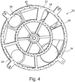
- FIG Fig. 1 A filter plate 50 of a filter device 10 according to the invention is shown in FIG Fig. 1 shown.
- the filter plate 50 has a plurality of disk segment-like or cake-shaped filter cells 60.
- the filter plate 50 is a total of 36 filter cells constructed, each forming an angular segment of 10 ° and are attached to a central plate hub.
- a single filter cell 60 has a tray 62 formed of sheet metal, which is provided on its radially outwardly facing side with a rear wall 63.
- Support profiles 64 are provided along the radial upper edge, which together with transverse struts 67 form a support frame 66.
- the trough 62 has, in addition to side surfaces, a bottom 68 which is inclined radially inwardly to allow drainage of the filtrate to the central plate hub 52.
- the floor 68 is itself constructed by inclined floor surfaces 69, so that radially directed drainage channels 70 are formed.
- a radially inwardly directed end 61 of the filter cell 60 is formed as a mounting area. Via screw connections, not shown, the filter cell 60 can be releasably secured to the attachment area on the end face 61 on a connecting flange 53 on the outside of the drum-shaped plate hub 52.
- the annular connection flange 53 surrounds an inlet opening 54. In the attached state, filtrate can flow through the inlet opening 54 into the cylindrical plate hub 52 via a passage 65 in the end face 61 of the filter cell 60.
- a filter medium (not shown), in particular a filter cloth, is stretched on the support frame 66. Due to the applied differential pressure, a solid or filter cake is formed on the filter medium during the filtration process, while liquid from the filter material passes into the interior of a filter cell 60 and runs inwards towards the disk hub 52.
- Each filter cell 60 is formed as a self-supporting element, which is bolted via the end face 61 with the plate hub 52 and via corresponding screw along the radial support profiles 64 with the respective adjacent filter cells 60.
- a single filter cell 60 or a plurality of filter cells 60 can be released from the filter plate 50 for maintenance purposes, for example.
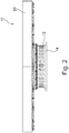
- FIG. 2 A side view of the filter device according to the invention is in Fig. 2 shown.
- the horizontal filter plate 50 is rotatably mounted about a vertical axis of rotation on a drum-shaped base frame 12 with a horizontal bottom plate 14.
- various treatment stations in particular a application station for applying the filter material to be filtered, one or more dehumidifying stations, where due to the applied differential pressure of the actual filtering process is performed, and a removal station to the remaining solids or remove filter cake from the top of the filter medium of the filter plate 50 and remove it from the pressure housing, not shown.
- an overpressure with a pressure unit in particular a known compressor, is set.
- the overpressure which is several bar, drives moisture from the debris of the applied filter material through the filter medium into the hollow chambers of the individual filter cells 60, from which the filtrate is discharged via the plate hub to a control head 30.
- a control head 30 is closer in Fig. 3 shown.
- the control head 30 has a plate-shaped upper side 32, which bears tightly against a corresponding plate-shaped underside 56 of the plate hub 52 of the filter plate 50. While the filter plate 50 is rotationally driven by a rotary drive, not shown, about a vertical axis of rotation, the control head 30 as well as the base frame 12 is rotationally fixed.
- the filter plate 50 is axially supported on the drum-shaped base frame 12 via an annular thrust bearing 20 and rotatably supported.
- the base frame 12 is fixedly connected to a bottom plate 14, which is also disposed within the pressure housing, not shown.
- the control head 30 is rotatably connected to the base frame 12 and thus does not rotate with the filter plate 50 with.
- the control head 30 is provided with a plurality of channels 34 for discharging filtrate from the disk hub 52 through respective through holes.
- the control head 30 is mounted axially movable to the plate hub 52.
- the lower discharge nozzle 36 are connected to the channels 34 of the control head 30 via flexible hose connections or Metallbalgkompensatoren with drain lines, not shown, which lead to the outside of the pressure housing.
- control head 30 preferably atmospheric pressure prevails, so that due to the overpressure in the pressure housing, the control head 30 is pressed with its top 32 tight against the corresponding bottom 56 of the plate hub 52. As a result, the interior is closed in the control head 30 pressure-tight with respect to the outer space in the pressure housing.
- the contact pressure on the control head 30 may be so large that due to the rotational movement of the filter plate 50, excessive friction in the area of the contact surface between the top 32 of the control head 30 and the bottom 56 of the plate hub 52 may occur.
- a counter-pressure device 40 is provided in the rubbing contact area, which in connection with Fig. 4 is shown and explained in detail.
- a multiplicity of disk-shaped and channel-shaped recesses 42 are introduced along the upper side 32 of the control head 30 in the contact surface to the disk hub 52, which are connected via channels, not shown, to a hydraulic pump of the counterpressure device 40.
- a hydraulic pressure between the top 32 of the control head 30 and the bottom 56 of the plate hub 52 are constructed, which counteracts an axial contact force of the control head 30 due to the external overpressure.
- the hydrostatic formation of a back pressure in the annular contact areas between the control head 30 and plate hub 52 also has a friction-reducing effect.
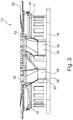
- a further second embodiment of a filter device 10 is shown, in which a modified counter-pressure device 40 is formed.
- a counter-pressure device 40 a plurality of adjusting cylinders 48 are arranged in a ring around the control head 30 distributed.
- An actuating cylinder 48 is connected at its upper side with radial retaining clips 37 of the control head 30.
- a lower part of the adjusting cylinder 48 is connected via beam-shaped supports 16 fixed to the base frame 12 and the bottom plate 14.
- the hydraulic adjusting cylinders 48 can be adjusted so that they pull the control head 30 axially against the upwardly directed axial contact force, so that the contact pressure is reduced and compensated to a desired extent.
- the filter device 10 With the counterpressure device 40, the filter device 10 according to the invention can be operated with a horizontally directed rotating filter plate 50 in a pressure housing with overpressure.
- the actuating cylinder 48 can also serve to ensure a necessary unfoldanpresskraft of the control head 30 to the plate hub 52.
Claims (14)
- Dispositif de filtre comprenant- un châssis de base (12),- un plateau de filtre (50) sensiblement horizontal, en forme de disque, lequel-- est monté de manière à pouvoir être entraîné en rotation sur le châssis de base (12),-- présente une pluralité de cellules de filtre (60) en forme de segment de disque et-- un moyeu de plateau (52), au niveau duquel les cellules de filtre (60) sont raccordées afin de dévier un filtrat au niveau d'ouvertures d'admission (54) du moyeu de plateau (52),- une tête de commande (30), qui est pourvue de canaux (34) servant à évacuer un filtrat du moyeu de plateau (52), la tête de commande (30) étant disposée de manière solidaire en rotation et de manière à pouvoir être déplacée axialement sous le moyeu de plateau (52) et repose à proximité immédiate au niveau d'un côté inférieur (56) du moyeu de plateau (52), et- un boîtier de pression,
caractérisé en ce- que le boîtier de pression renferme de manière étanche à la pression le plateau de filtre (50) et la tête de commande (30),- qu'une unité de pression est prévue, avec laquelle une surpression peut être réglée dans le boîtier de pression, et- que la surpression dans le boîtier de pression peut être réglée de telle manière que la tête de commande (30) est pressée axialement contre le côté inférieur (56) du moyeu de plateau (52). - Dispositif de filtre selon la revendication 1,
caractérisé en ce
que les cellules de filtre (60) sont réalisées de manière autoporteuse pour un montage individuel et sont fixées de manière facilement amovible au niveau du moyeu de plateau (52). - Dispositif de filtre selon la revendication 1 ou 2,
caractérisé en ce
que les cellules de filtre (60) sont réalisées de manière à présenter une forme de cuvette et présentent le long de leur arête périphérique radiale des profils porteurs (64). - Dispositif de filtre selon l'une des revendications 1 à 3,
caractérisé en ce
que les cellules de filtre (60) présentent un fond (68) incliné en direction du moyeu de plateau (52), lequel présente des surfaces de fond (69) inclinées dans la direction périphérique afin de former au moins un sillon d'évacuation (70) dans la section transversale. - Dispositif de filtre selon l'une des revendications 1 à 4,
caractérisé en ce
qu'au moins 24 cellules de filtre (60), de préférence 36 cellules de filtre (60), sont prévues afin de former le plateau de filtre (50). - Dispositif de filtre selon l'une des revendications 1 à 5,
caractérisé en ce
que le boîtier de pression présente au moins une ouverture pouvant être fermée de manière étanche à la pression, par laquelle diverses cellules de filtre (60) peuvent être introduites et sorties. - Dispositif de filtre selon la revendication 6,
caractérisé en ce
que le boîtier de pression est réalisé approximativement de manière cylindrique, avec une paroi périphérique en forme de tambour, un fond et un couvercle, et
que l'ouverture pouvant être fermée de manière étanche à la pression est disposée dans le fond et/ou dans le couvercle. - Dispositif de filtre selon l'une des revendications 1 à 7,
caractérisé en ce
que le plateau de filtre (50) est réalisé sous la forme d'une roue à rayons comprenant un châssis formé de rayons et d'un anneau périphérique, dans lequel les cellules de filtre (60) sont utilisées en tant que segments de disque de cercle. - Dispositif de filtre selon l'une des revendications 1 à 8,
caractérisé en ce
que la tête de commande (30) est disposée à l'intérieur d'un châssis de base (12) de forme annulaire et présente un côté supérieur (32) en forme de plaque, qui repose à proximité immédiate sur un côté inférieur (56) correspondant en forme de plaque du moyeu de plateau (52). - Dispositif de filtre selon l'une des revendications 1 à 9,
caractérisé en ce
qu'un système de compression est prévu, par lequel la tête de commande (30) est pressée contre le moyeu de plateau (52) afin de garantir une pression de compression minimale. - Dispositif de filtre selon l'une des revendications 1 à 10,
caractérisé en ce
qu'un système de contre-pression est prévu, par lequel une contre-force qui agit sur la tête de commande (30) peut être appliquée sur la tête de commande (30) afin de réduire une force de compression. - Dispositif de filtre selon la revendication 11,
caractérisé en ce
que le système de contre-pression (40) présente un système de pression hydrostatique, qui est disposé entre le moyeu de plateau (52) et la tête de commande (30). - Dispositif de filtre selon la revendication 11 ou 12,
caractérisé en ce
que le système de contre-pression (40) comprend au moins un vérin de réglage (48), en particulier un vérin hydraulique. - Procédé de filtration, qui est mis en oeuvre avec un dispositif de filtre (10) selon l'une des revendications 1 à 12,
caractérisé en ce
qu'une surpression est réglée dans le boîtier de pression au moyen d'une unité de pression, dans lequel la tête de commande (30) est compressée axialement contre le côté inférieur (56) du moyeu de plateau (52).
Priority Applications (4)
| Application Number | Priority Date | Filing Date | Title |
|---|---|---|---|
| EP14163350.3A EP2926879B1 (fr) | 2014-04-03 | 2014-04-03 | Dispositif de filtre et procédé de filtration |
| CA2885488A CA2885488C (fr) | 2014-04-03 | 2015-03-18 | Filtre rotatif plat avec cellules sementees fonctionnant en surpression |
| US14/663,708 US20150283485A1 (en) | 2014-04-03 | 2015-03-20 | Filter device and filtration method |
| CN201510154987.7A CN104971536B (zh) | 2014-04-03 | 2015-04-02 | 过滤设备及过滤方法 |
Applications Claiming Priority (1)
| Application Number | Priority Date | Filing Date | Title |
|---|---|---|---|
| EP14163350.3A EP2926879B1 (fr) | 2014-04-03 | 2014-04-03 | Dispositif de filtre et procédé de filtration |
Publications (2)
| Publication Number | Publication Date |
|---|---|
| EP2926879A1 EP2926879A1 (fr) | 2015-10-07 |
| EP2926879B1 true EP2926879B1 (fr) | 2017-09-27 |
Family
ID=50424117
Family Applications (1)
| Application Number | Title | Priority Date | Filing Date |
|---|---|---|---|
| EP14163350.3A Active EP2926879B1 (fr) | 2014-04-03 | 2014-04-03 | Dispositif de filtre et procédé de filtration |
Country Status (4)
| Country | Link |
|---|---|
| US (1) | US20150283485A1 (fr) |
| EP (1) | EP2926879B1 (fr) |
| CN (1) | CN104971536B (fr) |
| CA (1) | CA2885488C (fr) |
Families Citing this family (5)
| Publication number | Priority date | Publication date | Assignee | Title |
|---|---|---|---|---|
| SE536441C2 (sv) * | 2012-06-13 | 2013-11-05 | Metso Paper Sweden Ab | Metod och utrustning för mätning av filtersektorer i skivfilter |
| WO2015066803A1 (fr) * | 2013-11-08 | 2015-05-14 | Hugues Wanlin | Système rotatif à vide et tamis et procédés de séparation de solides et liquides |
| DE102015209094A1 (de) * | 2015-05-19 | 2016-11-24 | Bhs-Sonthofen Gmbh | Filtervorrichtung |
| KR20200096279A (ko) * | 2017-12-19 | 2020-08-11 | 제로스 리미티드 | 처리 장치용 필터 |
| CN113364179B (zh) * | 2021-06-21 | 2023-03-14 | 上海盘毂动力科技股份有限公司 | 一种降低涡流损耗的转子 |
Family Cites Families (13)
| Publication number | Priority date | Publication date | Assignee | Title |
|---|---|---|---|---|
| US2818177A (en) * | 1954-09-10 | 1957-12-31 | Dorr Oliver Inc | Continuous rotary filter |
| US2798612A (en) * | 1954-09-20 | 1957-07-09 | Dorr Oliver Inc | Sealed horizontal filter |
| DE1102105B (de) * | 1958-11-28 | 1961-03-16 | Dorr Oliver Inc | Drehbares Tischfilter |
| US3361262A (en) * | 1965-12-30 | 1968-01-02 | Dorr Oliver Inc | Rotary table filter |
| US3485375A (en) * | 1966-03-09 | 1969-12-23 | Dorr Oliver Inc | Rotary table filter construction |
| DE2015089A1 (en) * | 1970-03-28 | 1971-10-21 | Maschinenfabrik Buckau R. WoIfAG, 4048 Grevenbroich | Pressure-tight planar cell rotary filter |
| CA1219530A (fr) * | 1982-12-22 | 1987-03-24 | Rune H. Frykhult | Filtre tournant |
| AT398706B (de) * | 1992-11-06 | 1995-01-25 | Andritz Patentverwaltung | Verfahren und vorrichtung zur filtration |
| US6116431A (en) * | 1999-04-02 | 2000-09-12 | Bartec | Filter pan construction |
| PL1648587T3 (pl) * | 2003-06-16 | 2011-04-29 | Smidth As F L | Instalacja i sposób filtrowania zawiesiny |
| CN102228755A (zh) * | 2011-04-29 | 2011-11-02 | 江苏国祯环保科技有限公司 | 模块化过滤单元结构的转盘过滤器 |
| SG11201403813TA (en) * | 2012-01-03 | 2014-09-26 | New Way Machine Components Inc | Air bearing for use as seal |
| CN203183794U (zh) * | 2013-04-03 | 2013-09-11 | 杭州化工机械有限公司 | 加压转台过滤机 |
-
2014
- 2014-04-03 EP EP14163350.3A patent/EP2926879B1/fr active Active
-
2015
- 2015-03-18 CA CA2885488A patent/CA2885488C/fr active Active
- 2015-03-20 US US14/663,708 patent/US20150283485A1/en not_active Abandoned
- 2015-04-02 CN CN201510154987.7A patent/CN104971536B/zh active Active
Non-Patent Citations (1)
| Title |
|---|
| None * |
Also Published As
| Publication number | Publication date |
|---|---|
| EP2926879A1 (fr) | 2015-10-07 |
| CN104971536A (zh) | 2015-10-14 |
| CN104971536B (zh) | 2019-08-23 |
| CA2885488C (fr) | 2023-01-24 |
| CA2885488A1 (fr) | 2015-10-03 |
| US20150283485A1 (en) | 2015-10-08 |
Similar Documents
| Publication | Publication Date | Title |
|---|---|---|
| EP2926879B1 (fr) | Dispositif de filtre et procédé de filtration | |
| EP0377054B1 (fr) | Filtre à pression | |
| EP1444025B1 (fr) | Filtre comportant des elements filtrants rotatifs en forme de disque | |
| WO2002100512A1 (fr) | Dispositif de filtre rotatif | |
| EP3154774B1 (fr) | Presse à vis sans fin pour comprimer et déshydrater une suspension et procédé de maintenance d'une telle presse | |
| EP0577854B1 (fr) | Dispositif de filtration | |
| EP0951930B1 (fr) | Procédé et appareil pour séparer des solides d'une suspension | |
| DE202005018806U1 (de) | Vorrichtung zum Filtern einer Trübe | |
| EP2002874B1 (fr) | Dispositif de filtration | |
| EP0227084A1 (fr) | Filtre-presse | |
| DE3247440A1 (de) | Filterapparat | |
| EP1286781A1 (fr) | Centrifugeuse avec ensemble tamis et son procede de fonctionnement | |
| DE3622103A1 (de) | Scheiben - membran - pressfilter | |
| DE10005796A1 (de) | Drehfilteranlage | |
| EP3368196B1 (fr) | Ensemble filtre tournant doté de plusieurs arbres creux | |
| WO2017071974A1 (fr) | Ensemble filtre rotatif doté de plusieurs arbres creux | |
| DE102015121163A1 (de) | Schneckenpresse sowie Verfahren zur Wartung derselben | |
| DE484963C (de) | Dreh-Planfilter | |
| EP0655934B1 (fr) | Filtre sous pression | |
| AT13953U1 (de) | Scheibenfilter-Hohlwelle | |
| DE453507C (de) | Filtervorrichtung | |
| WO2002076573A1 (fr) | Filtre rotatif a plusieurs etages | |
| DE2353620C3 (de) | Filterteller für ein Plandrehfilter | |
| DE102017105301A1 (de) | Friktionswäscher | |
| EP3095499A1 (fr) | Dispositif de filtre |
Legal Events
| Date | Code | Title | Description |
|---|---|---|---|
| PUAI | Public reference made under article 153(3) epc to a published international application that has entered the european phase |
Free format text: ORIGINAL CODE: 0009012 |
|
| AK | Designated contracting states |
Kind code of ref document: A1 Designated state(s): AL AT BE BG CH CY CZ DE DK EE ES FI FR GB GR HR HU IE IS IT LI LT LU LV MC MK MT NL NO PL PT RO RS SE SI SK SM TR |
|
| AX | Request for extension of the european patent |
Extension state: BA ME |
|
| 17P | Request for examination filed |
Effective date: 20160210 |
|
| RBV | Designated contracting states (corrected) |
Designated state(s): AL AT BE BG CH CY CZ DE DK EE ES FI FR GB GR HR HU IE IS IT LI LT LU LV MC MK MT NL NO PL PT RO RS SE SI SK SM TR |
|
| GRAP | Despatch of communication of intention to grant a patent |
Free format text: ORIGINAL CODE: EPIDOSNIGR1 |
|
| STAA | Information on the status of an ep patent application or granted ep patent |
Free format text: STATUS: GRANT OF PATENT IS INTENDED |
|
| INTG | Intention to grant announced |
Effective date: 20170613 |
|
| GRAS | Grant fee paid |
Free format text: ORIGINAL CODE: EPIDOSNIGR3 |
|
| GRAA | (expected) grant |
Free format text: ORIGINAL CODE: 0009210 |
|
| STAA | Information on the status of an ep patent application or granted ep patent |
Free format text: STATUS: THE PATENT HAS BEEN GRANTED |
|
| AK | Designated contracting states |
Kind code of ref document: B1 Designated state(s): AL AT BE BG CH CY CZ DE DK EE ES FI FR GB GR HR HU IE IS IT LI LT LU LV MC MK MT NL NO PL PT RO RS SE SI SK SM TR |
|
| REG | Reference to a national code |
Ref country code: GB Ref legal event code: FG4D Free format text: NOT ENGLISH |
|
| REG | Reference to a national code |
Ref country code: CH Ref legal event code: EP |
|
| REG | Reference to a national code |
Ref country code: AT Ref legal event code: REF Ref document number: 931463 Country of ref document: AT Kind code of ref document: T Effective date: 20171015 |
|
| REG | Reference to a national code |
Ref country code: IE Ref legal event code: FG4D Free format text: LANGUAGE OF EP DOCUMENT: GERMAN |
|
| REG | Reference to a national code |
Ref country code: DE Ref legal event code: R096 Ref document number: 502014005562 Country of ref document: DE |
|
| PG25 | Lapsed in a contracting state [announced via postgrant information from national office to epo] |
Ref country code: HR Free format text: LAPSE BECAUSE OF FAILURE TO SUBMIT A TRANSLATION OF THE DESCRIPTION OR TO PAY THE FEE WITHIN THE PRESCRIBED TIME-LIMIT Effective date: 20170927 Ref country code: LT Free format text: LAPSE BECAUSE OF FAILURE TO SUBMIT A TRANSLATION OF THE DESCRIPTION OR TO PAY THE FEE WITHIN THE PRESCRIBED TIME-LIMIT Effective date: 20170927 Ref country code: FI Free format text: LAPSE BECAUSE OF FAILURE TO SUBMIT A TRANSLATION OF THE DESCRIPTION OR TO PAY THE FEE WITHIN THE PRESCRIBED TIME-LIMIT Effective date: 20170927 Ref country code: SE Free format text: LAPSE BECAUSE OF FAILURE TO SUBMIT A TRANSLATION OF THE DESCRIPTION OR TO PAY THE FEE WITHIN THE PRESCRIBED TIME-LIMIT Effective date: 20170927 Ref country code: NO Free format text: LAPSE BECAUSE OF FAILURE TO SUBMIT A TRANSLATION OF THE DESCRIPTION OR TO PAY THE FEE WITHIN THE PRESCRIBED TIME-LIMIT Effective date: 20171227 |
|
| REG | Reference to a national code |
Ref country code: NL Ref legal event code: MP Effective date: 20170927 |
|
| REG | Reference to a national code |
Ref country code: LT Ref legal event code: MG4D |
|
| PG25 | Lapsed in a contracting state [announced via postgrant information from national office to epo] |
Ref country code: GR Free format text: LAPSE BECAUSE OF FAILURE TO SUBMIT A TRANSLATION OF THE DESCRIPTION OR TO PAY THE FEE WITHIN THE PRESCRIBED TIME-LIMIT Effective date: 20171228 Ref country code: RS Free format text: LAPSE BECAUSE OF FAILURE TO SUBMIT A TRANSLATION OF THE DESCRIPTION OR TO PAY THE FEE WITHIN THE PRESCRIBED TIME-LIMIT Effective date: 20170927 Ref country code: BG Free format text: LAPSE BECAUSE OF FAILURE TO SUBMIT A TRANSLATION OF THE DESCRIPTION OR TO PAY THE FEE WITHIN THE PRESCRIBED TIME-LIMIT Effective date: 20171227 Ref country code: LV Free format text: LAPSE BECAUSE OF FAILURE TO SUBMIT A TRANSLATION OF THE DESCRIPTION OR TO PAY THE FEE WITHIN THE PRESCRIBED TIME-LIMIT Effective date: 20170927 |
|
| REG | Reference to a national code |
Ref country code: DE Ref legal event code: R082 Ref document number: 502014005562 Country of ref document: DE Representative=s name: WUNDERLICH & HEIM PATENTANWAELTE PARTNERSCHAFT, DE |
|
| PG25 | Lapsed in a contracting state [announced via postgrant information from national office to epo] |
Ref country code: NL Free format text: LAPSE BECAUSE OF FAILURE TO SUBMIT A TRANSLATION OF THE DESCRIPTION OR TO PAY THE FEE WITHIN THE PRESCRIBED TIME-LIMIT Effective date: 20170927 |
|
| PG25 | Lapsed in a contracting state [announced via postgrant information from national office to epo] |
Ref country code: CZ Free format text: LAPSE BECAUSE OF FAILURE TO SUBMIT A TRANSLATION OF THE DESCRIPTION OR TO PAY THE FEE WITHIN THE PRESCRIBED TIME-LIMIT Effective date: 20170927 Ref country code: RO Free format text: LAPSE BECAUSE OF FAILURE TO SUBMIT A TRANSLATION OF THE DESCRIPTION OR TO PAY THE FEE WITHIN THE PRESCRIBED TIME-LIMIT Effective date: 20170927 Ref country code: ES Free format text: LAPSE BECAUSE OF FAILURE TO SUBMIT A TRANSLATION OF THE DESCRIPTION OR TO PAY THE FEE WITHIN THE PRESCRIBED TIME-LIMIT Effective date: 20170927 |
|
| PG25 | Lapsed in a contracting state [announced via postgrant information from national office to epo] |
Ref country code: IS Free format text: LAPSE BECAUSE OF FAILURE TO SUBMIT A TRANSLATION OF THE DESCRIPTION OR TO PAY THE FEE WITHIN THE PRESCRIBED TIME-LIMIT Effective date: 20180127 Ref country code: EE Free format text: LAPSE BECAUSE OF FAILURE TO SUBMIT A TRANSLATION OF THE DESCRIPTION OR TO PAY THE FEE WITHIN THE PRESCRIBED TIME-LIMIT Effective date: 20170927 Ref country code: IT Free format text: LAPSE BECAUSE OF FAILURE TO SUBMIT A TRANSLATION OF THE DESCRIPTION OR TO PAY THE FEE WITHIN THE PRESCRIBED TIME-LIMIT Effective date: 20170927 Ref country code: SK Free format text: LAPSE BECAUSE OF FAILURE TO SUBMIT A TRANSLATION OF THE DESCRIPTION OR TO PAY THE FEE WITHIN THE PRESCRIBED TIME-LIMIT Effective date: 20170927 Ref country code: SM Free format text: LAPSE BECAUSE OF FAILURE TO SUBMIT A TRANSLATION OF THE DESCRIPTION OR TO PAY THE FEE WITHIN THE PRESCRIBED TIME-LIMIT Effective date: 20170927 |
|
| REG | Reference to a national code |
Ref country code: DE Ref legal event code: R097 Ref document number: 502014005562 Country of ref document: DE |
|
| PG25 | Lapsed in a contracting state [announced via postgrant information from national office to epo] |
Ref country code: DK Free format text: LAPSE BECAUSE OF FAILURE TO SUBMIT A TRANSLATION OF THE DESCRIPTION OR TO PAY THE FEE WITHIN THE PRESCRIBED TIME-LIMIT Effective date: 20170927 |
|
| PLBE | No opposition filed within time limit |
Free format text: ORIGINAL CODE: 0009261 |
|
| STAA | Information on the status of an ep patent application or granted ep patent |
Free format text: STATUS: NO OPPOSITION FILED WITHIN TIME LIMIT |
|
| PG25 | Lapsed in a contracting state [announced via postgrant information from national office to epo] |
Ref country code: PL Free format text: LAPSE BECAUSE OF FAILURE TO SUBMIT A TRANSLATION OF THE DESCRIPTION OR TO PAY THE FEE WITHIN THE PRESCRIBED TIME-LIMIT Effective date: 20170927 |
|
| 26N | No opposition filed |
Effective date: 20180628 |
|
| PG25 | Lapsed in a contracting state [announced via postgrant information from national office to epo] |
Ref country code: MT Free format text: LAPSE BECAUSE OF FAILURE TO SUBMIT A TRANSLATION OF THE DESCRIPTION OR TO PAY THE FEE WITHIN THE PRESCRIBED TIME-LIMIT Effective date: 20170927 |
|
| PG25 | Lapsed in a contracting state [announced via postgrant information from national office to epo] |
Ref country code: MC Free format text: LAPSE BECAUSE OF FAILURE TO SUBMIT A TRANSLATION OF THE DESCRIPTION OR TO PAY THE FEE WITHIN THE PRESCRIBED TIME-LIMIT Effective date: 20170927 Ref country code: SI Free format text: LAPSE BECAUSE OF FAILURE TO SUBMIT A TRANSLATION OF THE DESCRIPTION OR TO PAY THE FEE WITHIN THE PRESCRIBED TIME-LIMIT Effective date: 20170927 |
|
| REG | Reference to a national code |
Ref country code: CH Ref legal event code: PL |
|
| REG | Reference to a national code |
Ref country code: BE Ref legal event code: MM Effective date: 20180430 |
|
| GBPC | Gb: european patent ceased through non-payment of renewal fee |
Effective date: 20180403 |
|
| REG | Reference to a national code |
Ref country code: IE Ref legal event code: MM4A |
|
| PG25 | Lapsed in a contracting state [announced via postgrant information from national office to epo] |
Ref country code: LU Free format text: LAPSE BECAUSE OF NON-PAYMENT OF DUE FEES Effective date: 20180403 |
|
| PG25 | Lapsed in a contracting state [announced via postgrant information from national office to epo] |
Ref country code: BE Free format text: LAPSE BECAUSE OF NON-PAYMENT OF DUE FEES Effective date: 20180430 Ref country code: LI Free format text: LAPSE BECAUSE OF NON-PAYMENT OF DUE FEES Effective date: 20180430 Ref country code: CH Free format text: LAPSE BECAUSE OF NON-PAYMENT OF DUE FEES Effective date: 20180430 Ref country code: GB Free format text: LAPSE BECAUSE OF NON-PAYMENT OF DUE FEES Effective date: 20180403 |
|
| PG25 | Lapsed in a contracting state [announced via postgrant information from national office to epo] |
Ref country code: FR Free format text: LAPSE BECAUSE OF NON-PAYMENT OF DUE FEES Effective date: 20180430 Ref country code: IE Free format text: LAPSE BECAUSE OF NON-PAYMENT OF DUE FEES Effective date: 20180403 |
|
| PG25 | Lapsed in a contracting state [announced via postgrant information from national office to epo] |
Ref country code: TR Free format text: LAPSE BECAUSE OF FAILURE TO SUBMIT A TRANSLATION OF THE DESCRIPTION OR TO PAY THE FEE WITHIN THE PRESCRIBED TIME-LIMIT Effective date: 20170927 |
|
| PG25 | Lapsed in a contracting state [announced via postgrant information from national office to epo] |
Ref country code: PT Free format text: LAPSE BECAUSE OF FAILURE TO SUBMIT A TRANSLATION OF THE DESCRIPTION OR TO PAY THE FEE WITHIN THE PRESCRIBED TIME-LIMIT Effective date: 20170927 |
|
| PG25 | Lapsed in a contracting state [announced via postgrant information from national office to epo] |
Ref country code: HU Free format text: LAPSE BECAUSE OF FAILURE TO SUBMIT A TRANSLATION OF THE DESCRIPTION OR TO PAY THE FEE WITHIN THE PRESCRIBED TIME-LIMIT; INVALID AB INITIO Effective date: 20140403 Ref country code: CY Free format text: LAPSE BECAUSE OF FAILURE TO SUBMIT A TRANSLATION OF THE DESCRIPTION OR TO PAY THE FEE WITHIN THE PRESCRIBED TIME-LIMIT Effective date: 20170927 Ref country code: MK Free format text: LAPSE BECAUSE OF NON-PAYMENT OF DUE FEES Effective date: 20170927 |
|
| PG25 | Lapsed in a contracting state [announced via postgrant information from national office to epo] |
Ref country code: AL Free format text: LAPSE BECAUSE OF FAILURE TO SUBMIT A TRANSLATION OF THE DESCRIPTION OR TO PAY THE FEE WITHIN THE PRESCRIBED TIME-LIMIT Effective date: 20170927 |
|
| P01 | Opt-out of the competence of the unified patent court (upc) registered |
Effective date: 20230509 |
|
| PGFP | Annual fee paid to national office [announced via postgrant information from national office to epo] |
Ref country code: DE Payment date: 20230426 Year of fee payment: 10 |
|
| PGFP | Annual fee paid to national office [announced via postgrant information from national office to epo] |
Ref country code: AT Payment date: 20230414 Year of fee payment: 10 |