EP2926754A2 - Dispositifs électrochirurgicaux comprenant des configurations transversales d'électrode - Google Patents
Dispositifs électrochirurgicaux comprenant des configurations transversales d'électrode Download PDFInfo
- Publication number
- EP2926754A2 EP2926754A2 EP14200408.4A EP14200408A EP2926754A2 EP 2926754 A2 EP2926754 A2 EP 2926754A2 EP 14200408 A EP14200408 A EP 14200408A EP 2926754 A2 EP2926754 A2 EP 2926754A2
- Authority
- EP
- European Patent Office
- Prior art keywords
- tissue
- end effector
- jaw members
- effector assembly
- exterior
- Prior art date
- Legal status (The legal status is an assumption and is not a legal conclusion. Google has not performed a legal analysis and makes no representation as to the accuracy of the status listed.)
- Withdrawn
Links
Images


Classifications
-
- A—HUMAN NECESSITIES
- A61—MEDICAL OR VETERINARY SCIENCE; HYGIENE
- A61B—DIAGNOSIS; SURGERY; IDENTIFICATION
- A61B18/00—Surgical instruments, devices or methods for transferring non-mechanical forms of energy to or from the body
- A61B18/04—Surgical instruments, devices or methods for transferring non-mechanical forms of energy to or from the body by heating
- A61B18/12—Surgical instruments, devices or methods for transferring non-mechanical forms of energy to or from the body by heating by passing a current through the tissue to be heated, e.g. high-frequency current
- A61B18/14—Probes or electrodes therefor
- A61B18/1442—Probes having pivoting end effectors, e.g. forceps
- A61B18/1445—Probes having pivoting end effectors, e.g. forceps at the distal end of a shaft, e.g. forceps or scissors at the end of a rigid rod
-
- A—HUMAN NECESSITIES
- A61—MEDICAL OR VETERINARY SCIENCE; HYGIENE
- A61B—DIAGNOSIS; SURGERY; IDENTIFICATION
- A61B18/00—Surgical instruments, devices or methods for transferring non-mechanical forms of energy to or from the body
- A61B18/04—Surgical instruments, devices or methods for transferring non-mechanical forms of energy to or from the body by heating
- A61B18/12—Surgical instruments, devices or methods for transferring non-mechanical forms of energy to or from the body by heating by passing a current through the tissue to be heated, e.g. high-frequency current
- A61B18/14—Probes or electrodes therefor
- A61B18/1442—Probes having pivoting end effectors, e.g. forceps
-
- A—HUMAN NECESSITIES
- A61—MEDICAL OR VETERINARY SCIENCE; HYGIENE
- A61B—DIAGNOSIS; SURGERY; IDENTIFICATION
- A61B18/00—Surgical instruments, devices or methods for transferring non-mechanical forms of energy to or from the body
- A61B2018/00571—Surgical instruments, devices or methods for transferring non-mechanical forms of energy to or from the body for achieving a particular surgical effect
- A61B2018/0063—Sealing
-
- A—HUMAN NECESSITIES
- A61—MEDICAL OR VETERINARY SCIENCE; HYGIENE
- A61B—DIAGNOSIS; SURGERY; IDENTIFICATION
- A61B18/00—Surgical instruments, devices or methods for transferring non-mechanical forms of energy to or from the body
- A61B18/04—Surgical instruments, devices or methods for transferring non-mechanical forms of energy to or from the body by heating
- A61B18/12—Surgical instruments, devices or methods for transferring non-mechanical forms of energy to or from the body by heating by passing a current through the tissue to be heated, e.g. high-frequency current
- A61B18/14—Probes or electrodes therefor
- A61B18/1442—Probes having pivoting end effectors, e.g. forceps
- A61B2018/1452—Probes having pivoting end effectors, e.g. forceps including means for cutting
- A61B2018/1455—Probes having pivoting end effectors, e.g. forceps including means for cutting having a moving blade for cutting tissue grasped by the jaws
-
- A—HUMAN NECESSITIES
- A61—MEDICAL OR VETERINARY SCIENCE; HYGIENE
- A61B—DIAGNOSIS; SURGERY; IDENTIFICATION
- A61B18/00—Surgical instruments, devices or methods for transferring non-mechanical forms of energy to or from the body
- A61B18/04—Surgical instruments, devices or methods for transferring non-mechanical forms of energy to or from the body by heating
- A61B18/12—Surgical instruments, devices or methods for transferring non-mechanical forms of energy to or from the body by heating by passing a current through the tissue to be heated, e.g. high-frequency current
- A61B18/14—Probes or electrodes therefor
- A61B18/1442—Probes having pivoting end effectors, e.g. forceps
- A61B2018/146—Scissors
-
- A—HUMAN NECESSITIES
- A61—MEDICAL OR VETERINARY SCIENCE; HYGIENE
- A61B—DIAGNOSIS; SURGERY; IDENTIFICATION
- A61B18/00—Surgical instruments, devices or methods for transferring non-mechanical forms of energy to or from the body
- A61B18/04—Surgical instruments, devices or methods for transferring non-mechanical forms of energy to or from the body by heating
- A61B18/12—Surgical instruments, devices or methods for transferring non-mechanical forms of energy to or from the body by heating by passing a current through the tissue to be heated, e.g. high-frequency current
- A61B18/14—Probes or electrodes therefor
- A61B2018/1467—Probes or electrodes therefor using more than two electrodes on a single probe
Definitions
- the present disclosure relates to electrosurgical devices and, more particularly, to transverse electrode configurations for end effector assemblies of electrosurgical devices.
- Electrosurgical devices are utilized to apply energy to tissue to achieve a desired tissue effect.
- Electrosurgical forceps for example, utilize both mechanical clamping action and energy to affect hemostasis by heating tissue to coagulate and/or cauterize tissue.
- Certain surgical procedures require more than simply cauterizing tissue and rely on the unique combination of clamping pressure, gap distance, and energy control to "seal" tissue.
- energy is conducted between opposed jaw members and through tissue grasped therebetween, e.g., generally perpendicular to the plane extending between the jaw members, to seal or otherwise treat tissue.
- the jaw members may be configured such that energy is conducted transversely across the jaw members and through tissue grasped therebetween, e.g., generally parallel to the plane extending between the jaw members, to seal or otherwise treat tissue.
- the energy control parameters and/or physical characteristics of the end effector assembly for creating an effective tissue seal may vary depending upon whether energy is conducted between opposed jaw members or transversely relative to the jaw members.
- end effector assemblies that incorporate features configured to facilitate tissue sealing wherein electrosurgical energy is conducted transversely across the jaw members and through tissue grasped therebetween to seal tissue.
- distal refers to the portion that is being described which is further from a user
- proximal refers to the portion that is being described which is closer to a user.
- an end effector assembly for an electrosurgical device generally including first and second jaw members movable relative to one another between a spaced-apart position and an approximated position.
- Each jaw member defines an opposed tissue-contacting surface.
- a portion or the entire tissue-contacting surface of the first jaw member and a portion or the entire tissue-contacting surface of the second jaw member cooperate to define a tissue grasping area therebetween.
- Tissue disposed between the jaw members is grasped within the tissue grasping area when the jaw members are moved to the approximated position.
- One or both of the jaw members includes an interior electrode disposed interiorly of the outer bounds of the tissue grasping area.
- One or both of the jaw members includes first and second exterior electrodes disposed exteriorly of the outer bounds of the tissue grasping area.
- the interior and exterior electrodes are configured to conduct energy therebetween and through tissue grasped within the tissue grasping area to seal tissue grasped within the tissue grasping area.
- the first and second exterior electrodes are electrically-conductive plates extending along opposite exterior lateral sides of either or both of the jaw members. More specifically, the plates may be positioned adjacent the exterior edges of the tissue grasping area.
- either or both of the jaw members defines a knife channel extending longitudinally therethrough.
- the knife channel divides the tissue grasping area into first and second tissue grasping area portions disposed on either side of the knife channel.
- the interior electrode may be disposed within the knife channel and may be configured to define a "U"-shaped transverse cross-section configuration. Further, the interior electrode may be positioned between the first and second tissue grasping area portions adjacent the interior edges of the first and second tissue grasping areas, or may be overlapping with the interior edges of the first and second tissue grasping area portions.
- the inner electrode extending about an outer periphery of the knife channel and defines an inner periphery of the tissue-contacting surface.
- the opposed tissue-contacting surfaces of the jaw members define different widths such that the tissue grasping area is defined between the entirety of one of the tissue-contacting surfaces and only a portion of the other tissue-contacting surface.
- the interior electrode is disposed in closer proximity to the tissue grasping area as compared to the exterior electrodes.
- either or both of the first and second jaw members include chamfered exterior lateral sides.
- the tissue grasping area defined by the first and second jaw members is less than about 8mm or, more particularly, less than about 6mm. Additionally or alternatively, in the approximated position, the tissue-contacting surfaces of the first and second jaw members define a minimum gap distance therebetween within a range of about 0.004 inches to about 0.006 inches.
- Another end effector assembly for an electrosurgical device includes first and second jaw members movable relative to one another between a spaced-apart position and an approximated position for grasping tissue therebetween.
- Either or both of the jaw members defines a knife channel extending longitudinally therethrough and a tissue-contacting surface surrounding the knife channel on at least three sides.
- the jaw member(s) further includes an interior electrode extending about an outer periphery of the knife channel and defining an inner periphery of the tissue-contacting surface, and an exterior electrode extending about an outer periphery of the jaw member and defining an outer periphery of the tissue-contacting surface.
- the interior and exterior electrodes are configured to conduct energy therebetween and through tissue grasped between the jaw members to seal tissue disposed between the outer and inner peripheries of the tissue-contacting surface.
- the interior and exterior electrodes are disposed in recesses defined within the tissue-contacting surface such that the electrodes and the tissue-contacting surface cooperate to define a planar surface.
- the interior and exterior electrodes are spaced by insulative material of the tissue contacting surface.
- the tissue-contacting surface and the interior and exterior electrodes define "U"-shaped configurations (in the plane of the tissue contacting surface).
- the tissue-contact surface and the interior and exterior electrodes may define oval-shaped configurations with each including an interruption configured to provide access to the knife channel.
- the interior and exterior electrodes may be configured such that they are spaced-apart an equal distance relative to one another along the entire lengths thereof.
- the end effector assembly is configured so that electrosurgical energy is conducted transversely across the jaw members between the interior and exterior electrode(s) and through tissue grasped between the jaw members to seal tissue.
- the interior and exterior electrodes are disposed on the same one of the jaw members.
- the present disclosure provides various embodiments of end effector assemblies that incorporate features configured to facilitate tissue sealing wherein electrosurgical energy is conducted transversely across the jaw members and through tissue grasped therebetween to seal tissue. Except where specifically noted as being mutually exclusive, any of the features detailed herein below may be used in conjunction with any or all of the features detailed herein, and may be embodied in any of the exemplary embodiments provided herein, combinations thereof, or in any other suitable end effector assembly.
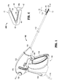
- FIG. 1 depicts an endoscopic electrosurgical forceps 100 for use in connection with endoscopic surgical procedures
- FIG. 2 depicts an open electrosurgical forceps 200 contemplated for use in connection with traditional open surgical procedures
- FIG. 3 depicts a reposable electrosurgical forceps 300 (which may be provided in either an endoscopic or open configuration)
- FIG. 4 depicts an electrosurgical tissue clip 400.
- forceps 100, forceps 200, forceps 300, clip 400, or any other suitable electrosurgical device may be utilized in implementing the aspects and features of the present disclosure. While different electrical and mechanical connections and considerations apply to each particular type of device, the aspects and features of the present disclosure detailed below and the operating characteristics thereof remain generally consistent regardless of the particular electrosurgical device used therewith.
- endoscopic electrosurgical forceps 100 defines a longitudinal axis "A-A" and includes a housing 120, a handle assembly 130, a rotating assembly 170, a trigger assembly 180, and an end effector assembly 10.
- Forceps 100 further includes a shaft 112 having a distal end 114 configured to mechanically engage end effector assembly 10 and a proximal end 116 that mechanically engages housing 120.
- a cable 119 connects forceps 100 to a source of energy, e.g., an external generator (not shown), although forceps 100 may alternatively be configured as a handheld device including a portable generator (not shown) disposed within housing 120.
- Cable 119 includes two or more wires (not shown) that extend into and through housing 120 and shaft 112 to connect the generator (not shown) to activation button 190 and end effector assembly 10 for selectively supplying energy to end effector assembly 10.
- End effector assembly 10 is shown attached at distal end 114 of shaft 112 and includes a pair of opposed jaw members 11, 12. Each jaw member 11, 12 includes a tissue-contacting surface 13, 14, respectively. One or more electrodes (not explicitly shown) is incorporated into either or both of jaw members 11, 12 and configured to conduct energy through tissue grasped between tissue-contacting surfaces 13,14 of jaw members 11, 12, respectively, to treat, e.g., seal, tissue.
- End effector assembly 10 is designed as a unilateral assembly, i.e., where jaw member 12 is fixed relative to shaft 112 and jaw member 11 is movable relative to shaft 112 and fixed jaw member 12.
- end effector assembly 10 may alternatively be configured as a bilateral assembly, i.e., where both jaw member 11 and jaw member 12 are movable relative to one another and to shaft 112.
- a knife assembly (not shown) is disposed within shaft 112 and a knife channel, e.g., similar to knife channel 54 of jaw member 52 ( FIGS. 5A-5B ), is defined within one or both jaw members 11, 12 to permit reciprocation of a knife blade (not shown) therethrough, e.g., upon activation of trigger 182 of trigger assembly 180, to cut sealed tissue.
- handle assembly 130 includes a fixed handle 150 and a movable handle 140.
- Fixed handle 150 is integrally associated with housing 120 and movable handle 140 is movable relative to fixed handle 150.
- Movable handle 140 is ultimately connected to a drive assembly (not shown) that, together, mechanically cooperate to impart movement of jaw members 11, 12 between a spaced-apart position and an approximated position for grasping tissue between tissue-contacting surfaces 13, 14 of jaw members 11, 12, respectively.
- movable handle 140 is initially spaced-apart from fixed handle 150 and, correspondingly, jaw members 11, 12 are disposed in the spaced-apart position.
- Movable handle 140 is depressible from this initial position to a depressed position corresponding to the approximated position of jaw members 11, 12.
- Rotating assembly 170 is rotatable in either direction about a longitudinal axis "A-A" to rotate end effector 10 about longitudinal axis "A-A.”
- open electrosurgical forceps 200 including two elongated shafts 212a, 212b each having a proximal end 216a, 216b and a distal end 214a, 214b, respectively.
- Forceps 200 includes an end effector assembly 20 having a pair of opposed jaw members 21, 22 that are attached to distal ends 214a, 214b of shafts 212a, 212b.
- Each shaft 212a, 212b further includes a handle 217a, 217b disposed at the proximal end 216a, 216b thereof.
- Each handle 217a, 217b defines a finger hole 218a, 218b therethrough for receiving a finger of the user.
- finger holes 218a, 218b facilitate movement of shafts 212a, 212b relative to one another from an open position, wherein jaw members 21, 22 are disposed in spaced-apart relation relative to one another, to a closed position, wherein jaw members 21, 22 cooperate to grasp tissue therebetween.
- a ratchet 230 may be included for selectively locking shafts 212a, 212b and, thus, jaw members 21, 22, at various different positions during pivoting.
- Ratchet 230 may include graduations or other visual markings that enable the user to easily and quickly ascertain and control the amount of closure force desired between the jaw members 21, 22.
- end effector assembly 20 is similar to end effector assembly 10 of forceps 100 (see FIG. 1 ).
- Jaw members 21, 22 of end effector assembly 20 each include a tissue-contacting surface 23, 24, respectively.
- Either or both of jaw members 21, 22 incorporate one or more electrodes (not explicitly shown) configured to facilitate the conduction of energy through tissue grasped between tissue-contacting surfaces 23, 24 of jaw members 21, 22, respectively, to treat, e.g., seal, tissue.
- forceps 200 may further include a knife assembly (not shown) disposed within either of the shafts, e.g., shaft 212b, and a knife channel, e.g., knife channel 54 of jaw member 52 ( FIGS. 5A-5B ), defined within one or both jaw members 21, 22 to permit reciprocation of a knife blade (not shown) therethrough, e.g., upon activation of trigger 282 of trigger assembly 280, to cut sealed tissue.
- reposable electrosurgical forceps 300 may be configured as an open forceps, e.g., similar to forceps 200 ( FIG. 2 ), an endoscopic forceps, e.g., similar to forceps 100 ( FIG. 1 ), or in any other suitable configuration.
- Reposable forceps 300 includes an end effector assembly 30 similar to end effector assemblies 10, 20 ( Figs. 1 , 2 , respectively), except that jaw members 31, 32 each include a fixed jaw frame 31 a, 32a and a removable jaw body 31 b, 32b, respectively. Jaw bodies 31b, 32b are removably engagable with respective jaw frames 31a, 32a and include tissue-contacting surfaces 33, 34, respectively.
- jaw bodies 31b, 32b further incorporate one or more electrodes (not explicitly shown) configured to facilitate the conduction of energy through tissue grasped between tissue-contacting surfaces 33, 34, to treat, e.g., seal, tissue.
- Electrodes 300 may otherwise be similar to and/or incorporate any of the features of forceps 100, 200 ( FIGS. 1 and 2 , respectively), detailed above.
- electrosurgical tissue clip 400 is an integrated or stand-alone end effector assembly including first and second jaw members 41, 42, respectively, coupled to one another by a flexible joint 43, although jaw members 41, 42 may alternatively be coupled to one another by a hinge, pivot, or any other suitable mechanism.
- Flexible joint 43 permits jaw members 41, 42 to move relative to one another between spaced-apart and approximated positions for grasping tissue therebetween.
- Jaw members 41, 42 of tissue clip 400 each further include contacting surface 44, 45, respectively, and either or both of jaw members 41, 42 incorporate one or more electrodes (not explicitly shown) therein.
- a miniaturized generator 46 is disposed within one of the jaw members, e.g., jaw member 42, for selectively supplying energy to the electrodes of either or both of jaw members 41, 42 for conduction through tissue grasped between tissue-contacting surfaces 44, 45 of jaw members 41, 42, respectively, to treat, e.g., seal, tissue.
- tissue clip 400 is a fully integrated tissue-treating unit incorporating all the necessary mechanical and electrical components for electrosurgically treating tissue.
- a latch mechanism 49 including first and second latch components 49a, 49b disposed on first and second jaw members 41, 42, respectively, may also be provided for selectively locking jaw members 41 and 42 relative to one another in various different positions.
- FIG. 5A-21 various embodiments of end effector assemblies configured for use with forceps 100 ( FIG. 1 ), forceps 200 ( FIG. 2 ), forceps 300 ( FIG. 3 ), tissue clip 400 ( FIG. 4 ), or any other suitable electrosurgical device, are shown.
- each of the embodiments of end effector assemblies detailed hereafter is configured to facilitate electrosurgical tissue sealing using transverse current flow; that is, electrosurgical tissue sealing wherein the electrosurgical energy is conducted transversely across the jaw members and through tissue grasped therebetween to seal tissue.
- end effector assembly 50 includes a pair of jaw members that cooperate to grasp tissue therebetween, similarly as detailed above, only jaw members 52 is shown.
- Both jaw members of end effector assembly 50 may be similar to jaw member 52 or, alternatively, only one of the jaw members, e.g., jaw member 52, may incorporate electrodes, while the other jaw member (not shown) simply provides an opposed tissue-contacting surface that is electrically insulated, for grasping tissue between the jaw members of end effector assembly 50.
- jaw member 52 is formed from an electrically insulating material and defines a tissue-contacting surface 53 having a knife channel 54 extending longitudinally therethrough. Knife channel 54 permits reciprocation of a knife blade (not shown) therethrough to cut tissue grasped between the jaw members of end effector assembly 50 after tissue has been sealed (or simply to cut the tissue where tissue sealing is not desired). Jaw member 52 further includes first and second electrodes formed as electrically-conductive plates 55, 56 disposed in the plane of tissue-contacting surface 53. Plates 55, 56 are seated within recesses defined within tissue-contacting surface 53 such that plates 55, 56 and tissue-contacting surface 53 cooperate to define a planar surface.
- Each plate 55, 56 defines a generally "U"-shaped configuration formed from first and second longitudinal sections 55a, 55b and 56a, 56b, respectively, interconnected by respective curved sections 55c, 56c.
- the radius of curvature of curved section 55c of first plate 55 is greater than that of curved section 56c of second plate 56, e.g., curved section 55c and curved section 56c define concentric arcs, enabling first plate 55 to extend about the outer periphery of tissue-contacting surface 53, while second plate 56 is positioned within first plate 55 and extends about the inner periphery of tissue-contacting surface 53, e.g., bordering knife channel 54.
- the width of plates 55, 56 and the spacing between plates 55, 56, which is filled via the insulated jaw member 52, is constant along the lengths of plates 55, 56.
- Jaw member 52 and/or the other jaw member (not shown) of end effector assembly 50 may include one or more stop members (not shown) or other stop features, e.g., mechanical stops in the drive assembly (not shown), configured to define a minimum gap distance between the tissue-contacting surfaces of the jaw members of end effector assembly 50 of between about 0.004 inches to about 0.006 inches (about 100 ⁇ m to about 150 ⁇ m) when approximated about tissue, as it has been found that a gap distance within this range promotes formation of an effective tissue seal.
- Such stop members or stop features (not shown) may be molded, casted, machined, deposited (e.g., via evaporation), adhered, or otherwise disposed on the jaw members or other components to achieve a minimum gap distance within the above-noted range.
- the above-noted gap distances and suitable structures and/or methods for establishing the same are equally applicable for use with any of the other end effector assemblies detailed herein.
- tissue is initially grasped between the jaw members of end effector assembly 50 such that a portion of tissue to be sealed is grasped within a tissue seal area defined by jaw member 52. More specifically, with sections 56a, 56b, 56c of plate 56 bordering knife channel 54 and with sections 55a, 55b, 55c of plate 55 bordering the outer periphery of the tissue-contacting surface 53 of jaw member 52, a generally "U"-shaped tissue seal area is defined between and bounded by plates 55, 56. Once tissue is grasped within this tissue seal area, first plate 55 of jaw member 52 is energized to a first electrical potential and second plate 56 of jaw member 52 is energized to a second, different electrical potential to establish an electrical potential gradient therebetween.
- tissue disposed therebetween e.g., tissue grasped within the tissue seal area
- This configuration facilitates formation of an effective tissue seal. Further, this configuration reduces thermal spread by eliminating alternate current paths through tissue since the plates 55, 56 are positioned to bound the tissue seal area and direct the flow of energy through tissue within the tissue seal area.
- a knife blade (not shown) may be reciprocated through knife channel 54 to cut tissue. Bleeding during tissue cutting is substantially reduced or eliminated due to the fact that tissue is sealed about the periphery of knife channel 54. That is, since tissue is sealed about the cutting path, little to no bleeding occurs upon subsequent advancement of a knife blade (not shown) along the cutting path to cut tissue.
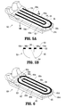
- End effector assembly 60 is similar to end effector assembly 50 ( FIGS. 5A-5B ) except that plates 65, 66 disposed on tissue-contacting surface 63 of jaw member 62 define generally oval-shaped configurations (as compared to the "U"-shaped configurations of plates 55, 56 of jaw member 52 ( FIGS. 5A-5B ).
- each plate 65, 66 includes first and second longitudinal sections 65a, 65b and 66a, 66b, respectively, interconnected at their respective proximal ends via proximal curved sections 65c, 66c and at their respective distal ends via distal curved sections 65d, 66d.
- Proximal curved sections 65c, 66c are mirror-images of distal curved sections 65d, 66d, respectively, except that proximal curved sections 65c, 66c define interruptions 65e, 66e spanning knife channel 64 to enable reciprocation of a knife blade (not shown) into and through knife channel 64 of jaw member 62.
- Boiling within tissue occurs when the temperature of tissue increases to a point where the vapor pressure of a component of tissue exceeds the ambient pressure within tissue. Boiling can be initiated at a particular location within tissue by raising the temperature at that location, by providing for a lower pressure at that location, or by utilizing both temperature and pressure differentials to ensure that the vapor pressure first exceeds the ambient pressure at that location.
- the two basic parameters that affect the boiling of tissue are: the temperature of tissue and the pressure within tissue.
- end effector assemblies are configured to control the temperature of tissue and/or the pressure applied to tissue so as to enable boiling to first occur at the outer edges of the portion of tissue to be sealed.
- these end effector assemblies are configured to facilitate formation of an effective tissue seal.
- an end effector assembly 70 provided in accordance with the present disclosure is shown including first and second jaw members 72, 74, respectively.
- Jaw member 72 is formed from an electrically insulating material and defines a tissue-contacting surface divided into first and second tissue-contacting surface portions 73a, 73b by a knife channel 75 extending longitudinally through jaw member 72.
- Jaw member 74 is likewise formed from an electrically insulating material and defines a tissue-contacting surface divided into first and second tissue-contacting surface portions 76a, 76b by a knife channel 77 having a width smaller than that of knife channel 75.
- Jaw member 74 includes a pair of exterior electrodes, in the form of electrically-conductive plates 78a, 78b extending along the exterior lateral sides of jaw member 74 and positioned adjacent the exterior edges of tissue-contacting surface portions 76a, 76b of jaw member 74. Jaw member 74 further includes an interior electrode, in the form of an electrically-conductive plate 79 defining a "U"-shaped transverse cross-section, surrounding the interior of knife channel 77 and positioned adjacent the interior edges of tissue-contacting surface portions 76a, 76b of jaw member 74.
- First and second tissue-contacting surface portions 73a, 73b of jaw member 72 define reduced widths as compared to respective first and second tissue-contacting surface portions 76a, 76b of jaw member 74 and are positioned closer towards plate 79 as compared to plates 78a, 78b. Further, upon approximation of jaw members 72, 74, as shown in FIG. 7 , tissue is grasped between tissue-contacting surface portions 76a, 76b of jaw member 74 and the opposed portions of tissue-contacting surfaces 73a, 73b of jaw member 72. No portion of any of plates 78a, 78b, 79 is utilized to grasp tissue therebetween.
- jaw members 72, 74, plates 78a, 78b, and 79 are disposed outside the tissue grasping areas defined between tissue-contacting surface portions 76a, 76b of jaw member 74 and the opposed portions of tissue-contacting surfaces 73a, 73b of jaw member 72, respectively.
- plates 78a, 78b are energized to a first electrical potential and plate 79 is energized to a second, different electrical potential to establish an electrical potential gradient therebetween.
- energy is conducted between plates 78a, 78b and plate 79, and through tissue grasped within the tissue grasping areas in a generally transverse direction relative to jaw members 72, 74. Due to the above-described configuration of end effector assembly 70, the thermal path between plate 79 and the interior edges of tissue disposed within the tissue grasping areas is shorter than the thermal path between plates 78a, 78b and the exterior edges of tissue disposed within the tissue grasping areas.
- end effector assembly 80 provided in accordance with the present disclosure is shown including first and second jaw members 82, 84, respectively.
- End effector assembly 80 is similar to end effector assembly 70 ( FIG. 7 ) except that, as detailed below, the internal electrode is disposed on the opposite jaw member.
- jaw member 82 is formed from an electrically insulating material and defines a tissue-contacting surface divided into first and second tissue-contacting surface portions 83a, 83b by a knife channel 85 extending longitudinally through jaw member 82.
- An interior electrode in the form of an electrically-conductive plate 89 defining a "U"-shaped transverse cross-section surrounds the interior of knife channel 85 and is positioned adjacent the interior edges of tissue-contacting surface portions 83a, 83b of jaw member 82.
- Jaw member 84 is likewise formed from an electrically insulating material and defines a tissue-contacting surface divided into first and second tissue-contacting surface portions 86a, 86b by a recess 87 having a width greater than that of knife channel 85.
- Jaw member 84 further includes a pair of exterior electrodes, in the form of electrically-conductive plates 88a, 88b extending along the exterior lateral sides of jaw member 84 and positioned adjacent the exterior edges of tissue-contacting surface portions 86a, 86b of jaw member 84. Similarly as detailed above, plates 88a, 88b, and 89 are disposed outside the tissue grasping areas defined by jaw members 82, 84.
- End effector assembly 80 is similar to end effector assembly 70 ( FIG. 7 ) in that the thermal path between plate 89 and the interior edges of tissue disposed within the tissue grasping areas is shorter than the thermal path between plates 88a, 88b and the exterior edges of tissue disposed within the tissue grasping areas.
- the thermal path between plate 89 and the interior edges of tissue disposed within the tissue grasping areas is shorter than the thermal path between plates 88a, 88b and the exterior edges of tissue disposed within the tissue grasping areas.
- end effector assemblies 90, 1100 provided in accordance with the present disclosure are shown each including first and second electrically insulating jaw members 92, 94 and 1102, 1104, respectively.
- End effector assembly 90 is similar to end effector assembly 70 ( FIG. 7 ), while end effector assembly 1100 is similar to end effector assembly 80 ( FIG. 8 ).
- end effector assemblies 90, 1100 differ from respective end effector assemblies 70, 80 ( FIGS. 7-8 , respectively) in that electrically-conductive plate 99 of jaw member 94 of end effector assembly 90 and electrically-conductive plate 1109 of jaw member 1102 of end effector assembly 1100 are partially overlapping with the tissue grasping areas defined by end effector assemblies 90, 1100, respectively.
- Electrically-conductive plates 98a, 98b of jaw member 94 of end effector assembly 90 and electrically-conductive plates 1108a, 1108b of jaw member 1104 of end effector assembly 1100 remain disposed outside the tissue grasping area of the respective end effector assembly 90, 1100.
- the thermal path between plates 99, 1109 and the interior edges of tissue disposed within the tissue grasping areas of end effector assemblies 90, 1100 is shorter than the thermal path between plates 98a, 98b and 1108a, 1108b and the exterior edges of tissue disposed within the tissue grasping areas of end effector assemblies 90, 1100.
- the interior electrode(s) may be formed from copper, while the exterior electrodes are formed from stainless steel. As such, since stainless steel is less effective at drawing heat away than is copper, the exterior edges of tissue disposed within the tissue grasping areas are heated and boil sooner.
- Other suitable materials having differing heat sinking properties may also be utilized in a similar fashion.
- tissue boiling first at the exterior edges of tissue disposed within the tissue grasping areas can also be accomplished, as an alternative to, or in addition to any of the above-detailed embodiments, by geometrically constructing the interior electrode and exterior electrodes (which are energized to conduct energy transversely therebetween) to have different heat sinking properties.
- End effector assembly 1110 is similar to end effector assembly 90 ( FIG. 9 ) and includes an interior electrode, in the form of an electrically-conductive plate 1119 defining a "U"-shaped transverse cross-section, disposed within knife channel 1117 of jaw member 1114, and a pair of exterior electrodes 1118a, 1118b disposed along the exterior lateral sides of jaw member 1114.
- Plate 1119 is partially overlapping with the tissue grasping areas defined between jaw members 1112, 1114, while electrodes 1118a, 1118b remain disposed outside the tissue grasping areas of end effector assembly 1110.
- End effector assembly 1110 differs from end effector assembly 90 ( FIG. 9 ) in that, rather both the interior and exterior electrodes being formed as plates having similar thicknesses, electrodes 1118a, 1118b are formed as thin strips of electrically-conductive material, while plate 1119 defines an increased thickness relative to electrodes 1118a, 1118b. As a result of electrodes 1118a, 1118b being thinner, electrodes 1118a, 1118b are less effective heat sinks as compared to the thicker plate 1119. Thus, the exterior edges of tissue disposed within the tissue grasping areas are heated faster and, thus, boil sooner, facilitating formation of an effective tissue seal.
- End effector assembly 1120 is similar to end effector assembly 1100 ( FIG. 10 ) and includes first and second electrically insulating jaw members 1122, 1124, respectively.
- An interior electrode in the form of an electrically-conductive plate 1129 defining a "U"-shaped transverse cross-section, is disposed within knife channel 1125 of jaw member 1122.
- a pair of exterior electrodes 1128a, 1128b are disposed along the exterior lateral sides of jaw member 1124. Plate 1129 is partially overlapping with the tissue grasping areas defined between jaw members 1122, 1124, while electrodes 1128a, 1128b remain disposed outside the tissue grasping areas of end effector assembly 1120.
- End effector assembly 1120 differs from end effector assembly 1100 ( FIG. 10 ) in that, rather both the interior and exterior electrodes being formed as plates having similar thick
- electrodes 1128a, 1128b are formed as hollow pipes of relatively thin, electrically-conductive material, while plate 1129 defines an increased thickness of electrically-conductive material relative to electrodes 1128a, 1128b.
- electrodes 1128a, 1128b are less effective heat sinks as compared to the thicker, solid plate 1129.
- the exterior edges of tissue disposed within the tissue grasping areas are heated faster and, thus, boil sooner, facilitating formation of an effective tissue seal.
- FIG. 13 illustrates another embodiment of an end effector assembly provided in accordance with the present disclosure and shown generally identified by reference numeral 1130.
- End effector assembly 1130 is similar to end effector assembly 80 ( FIG. 8 ) and includes first and second electrically insulating jaw members 1132, 1134, respectively.
- Jaw member 1132 includes an electrode 1139 defining a "U"-shaped transverse cross-section disposed within knife channel 1135 thereof.
- Electrode 1139 is formed as a thin strip of electrically-conductive material that is folded back upon itself over at least a portion thereof. This folded configuration of electrode 1139 functions to increase the effective thickness of electrode 1139, thereby increasing the heat sinking properties of electrode 1139.
- Jaw member 1134 includes a pair of exterior electrodes 1138a, 1138b, in the form of thin strips of electrically-conductive material, that extend along the exterior lateral sides of jaw member 1134 and over the outer peripheral edges of the tissue-contacting surface of jaw member 1134. Exterior electrodes 1138a, 1138b, although bent at the edges of jaw member 1134, are not folded back upon themselves, and, thus, do not have the increased heat sinking properties of electrode 1139. Thus, the exterior edges of tissue disposed within the tissue grasping areas are heated faster and, thus, boil sooner, facilitating formation of an effective tissue seal.
- establishing a relatively lower pressure adjacent the exterior edges of tissue disposed within the tissue grasping areas and a relatively higher pressure adjacent the grasped tissue and/or interior edges of tissue disposed within the tissue grasping areas facilitates heating and boiling of the exterior edges of tissue disposed within the tissue grasping areas first.
- the various embodiments of end effector assemblies detailed below with respect to FIGS. 14-16 are configured to achieve such a pressure differential, thus facilitating formation of an effective tissue seal.
- end effector assembly 1140 is shown including first and second electrically insulating jaw members 1142, 1144, each defining a tissue-contacting surface 1143, 1146.
- jaw members 1142, 1144 may define a knife channel extending longitudinally therealong, similarly as any of the previous embodiments.
- Jaw member 1142 includes an electrode 1149 defining an elongated block-shaped configuration. Electrode 1149 is disposed intermediately between the electrically insulating portions of jaw member 1142 and is recessed within jaw member 1142 so as to define a planar tissue-contacting surface 1143.
- Jaw member 1144 includes a pair of electrodes 1148a, 1148b formed as plates extending along the exterior lateral sides of jaw member 1144 and positioned adjacent the exterior edges of tissue-contacting surface 1146 of jaw member 1144. Electrode 1149 defines a greater width than both of electrodes 1148a, 1148b. Similarly as with the embodiments of FIGS. 7-13 , jaw members 1142, 1144 are configured such that tissue-contacting surface 1146 of jaw member 1144 defines a greater width as compared to tissue-contacting surface 1143 of jaw member 1142.
- electrode 1149 is positioned within the tissue grasping area of jaw members 1142, 1144, which is defined as the area between tissue-contacting surfaces 1143 and the opposed portion of tissue-contacting surface 1146, while electrodes 1148a, 1148b are disposed outside the tissue grasping area of end effector assembly 1140.
- tissue is initially grasped within the tissue grasping area, e.g., between tissue-contacting surfaces 1143 and the opposed portion of tissue-contacting surface 1146, such that electrode 1149 is positioned adjacent the interior section of tissue disposed within the tissue grasping area, while electrodes 1148a, 1148b are disposed outside the tissue grasping area adjacent the exterior edges of tissue disposed within the tissue grasping area.
- the pressure applied to tissue in the vicinity of electrode 1149 is greater than the pressure applied to tissue in the vicinity of electrodes 1148a, 1148b.
- the above-noted pressure differential enables the exterior edges of tissue disposed at the exterior boundaries of the tissue sealing area to boil at a relatively lower temperature than the interior portions (as a result of the pressure differential therebetween) and, thus, to boil sooner, facilitating formation of an effective tissue seal.
- jaw member 1152 is formed from an electrically insulating material and defines a tissue-contacting surface divided into first and second tissue-contacting surface portions 1153a, 1153b by a knife channel 1155 extending longitudinally through jaw member 1152.
- a first interior electrode in the form of an electrically-conductive plate 1159a defining a "U"-shaped transverse cross-section surrounds the interior of knife channel 1155 and is positioned adjacent the interior edges of tissue-contacting surface portions 1153a, 1153b of jaw member 1152.
- Jaw member 1154 is likewise formed from an electrically insulating material and defines a tissue-contacting surface divided into first and second tissue-contacting surface portions 1156a, 1156b by a knife channel 1157.
- Jaw member 1154 includes a pair of exterior electrodes, in the form of electrically-conductive plates 1158a, 1158b extending along the exterior lateral sides of jaw member 1154 and positioned adjacent the exterior edges of tissue-contacting surface portions 1156a, 1156b of jaw member 1154.
- Jaw member 1154 further includes a second interior electrode, in the form of an electrically-conductive plate 1159b defining a "U"-shaped transverse cross-section, surrounding the interior of knife channel 1157 and positioned adjacent the interior edges of tissue-contacting surface portions 1156a, 1156b of jaw member 1154.
- electrodes 1158a, 1158b are disposed outside the tissue grasping area of end effector assembly 1150.
- tissue is initially grasped between jaw members 1152, 1154. That is, tissue is grasped within tissue grasping areas defined between the surfaces formed by tissue-contacting surface portions 1153a, 1153b and electrode 1159, and the surfaces formed by tissue-contacting surface portions 1156a, 1156b and electrode 1159b.
- electrodes 1158a, 1158b are disposed outside the tissue grasping area. As a result of this configuration, the pressure applied to tissue in the vicinity of electrodes 1159a, 1159b is greater than the pressure applied to tissue in the vicinity of electrodes 1158a, 1158b.
- FIG. 16 illustrates another end effector assembly 1160 provided in accordance with the present disclosure.
- End effector assembly 1160 includes first and second jaw members 1162, 1164 defining tissue-contacting surfaces 1163, 1166, respectively, divided by respective knife channels 1165, 1167.
- Jaw members 1162, 1164 each further define chamfered exterior edges 1161 a, 1161b which interface between tissue-contacting surfaces 1163, 1166 and the respective exterior lateral sides of jaw members 1162, 1164.
- Either or both jaw members 1162, 1164 includes an interior electrode 1149a, 1149b defining a "U"-shaped transverse cross-section configuration and disposed within the respective knife channel 1165, 1167 thereof.
- each jaw member 1162, 1164 includes a pair of exterior electrodes, in the form of electrically-conductive plates 1168a, 1168b extending along the exterior lateral sides of jaw members 1162, 1164, respectively.
- Chamfered exterior edges 1161a, 1161b are positioned adjacent plates 1168a, 1168b, respectively, and interconnect plates 1168a, 1168b with respective tissue-contacting surfaces 1163, 1166, respectively.
- Plates 1168a, 1168b may further include chamfered surfaces corresponding to chamfered exterior edges 1161 a, 1161 b so as to define a continuous, planar chamfered surface at the edges of jaw members 1162, 1164, as shown in FIG. 16 .
- tissue is initially grasped between jaw members 1162, 1164. That is, tissue is grasped within tissue grasping areas defined between the surfaces formed by the divided portions of tissue-contacting surface 1163 and electrode 1169a, and the surfaces formed by the divided portions of tissue contacting surface 1166 and electrode 1169b. Due to the chamfered exterior edges 1161a, 1161b of jaw members 1162, 1164, plates 1168a, 1168b are further spaced-apart from one another as compared to tissue-contacting surfaces 1163, 1166. As a result, plates 1168a, 1168b exert a reduced pressure on the exterior edges of tissue disposed within the tissue grasping areas as compared to the pressure applied to the interior edges of tissue disposed within the grasping areas.
- an end effector assembly defining a tissue grasping area having a total width of less than about 8mm or, more particularly, less than about 6mm for use to seal tissue using transverse energy flow.
- Such a configuration also provides the benefit of being able to access small areas with the body endoscopically.
- providing such small jaw members difficulties in manufacturing. That is, the trade-off between providing sufficiently small structures and providing sufficient strength.
- the various embodiments of end effector assemblies detailed below with respect to FIGS. 17-21 achieved a desirable balance between size and strength.
- the jaw members of these end effector assemblies are manufactured by molding a polymeric material (forming the body of the jaw member), e.g., a biocompatible plastic, about the sheet metal electrodes (forming the electrodes of the jaw member) and sheet metal support members, if provided, although other suitable manufacturing techniques are also contemplated.
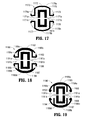
- an end effector assembly 1170 provided in accordance with the present disclosure is shown including first and second jaw members 1172, 1174, respectively.
- Jaw members 1172, 1174 define mirror image configurations of one another, although it is also contemplated that one of jaw members be provided with electrodes and the other jaw member simply provide an electrically insulating tissue-contacting surface for grasping tissue between jaw members 1172, 1174.
- First and second jaw members 1172, 1174 of end effector assembly 1170 are formed from an electrically insulating polymeric material, e.g., a biocompatible plastic, or other suitable electrically insulating material and define tissue-contacting surfaces 1173, 1176, respectively, divided by respective knife channels 1175, 1177. Jaw members 1172, 1174 each further define chamfered exterior edges 1171a, 1171b, similarly as detailed above with respect to end effector assembly 1160 ( FIG. 16 ), although other configurations are also contemplated.
- an electrically insulating polymeric material e.g., a biocompatible plastic, or other suitable electrically insulating material and define tissue-contacting surfaces 1173, 1176, respectively, divided by respective knife channels 1175, 1177.
- Jaw members 1172, 1174 each further define chamfered exterior edges 1171a, 1171b, similarly as detailed above with respect to end effector assembly 1160 ( FIG. 16 ), although other configurations are also contemplated.
- Each jaw member 1172, 1174 includes an interior electrode 1179a, 1179b in the form of a relatively thick piece of sheet metal bent to define a "U"-shaped transverse cross-section configuration and disposed within the respective knife channel 1175, 1177 of the jaw member 1172, 174, respectively.
- Each jaw member 1172, 1174 further includes an exterior electrode 1178a, 1178b, in the form of a relatively thin piece of sheet metal that extends along the exterior lateral sides of jaw members 1172, 1174, respectively. Exterior electrodes 1178a, 1178b are further routed through the respective jaw members 1172, 1174 and extend along an outer back surface (opposite the tissue-contacting surface) of the respective jaw members 1172, 1174.
- This configuration adds strength to jaw members 1172, 1174 and also enables a single piece of sheet metal to form both of the exterior electrodes 1178a, 1178b of the jaw member 1172, 1174, respectively.
- the ends of exterior electrodes 1178a, 1178b are bent adjacent the exterior lateral sides of jaw members 1172, 1174.
- Such a configuration provides an increased exposed surface area of exterior electrodes 1178a, 1178b in the vicinity of chamfered exterior edges 1171a, 1171b.
- end effector assembly 1170 functions similarly to end effector assembly 1160 ( FIG. 16 ), detailed above, and provides similar advantages with respect to tissue sealing using transverse energy flow.
- End effector assembly 1180 shown in FIG. 18 , is similar to end effector assembly 1170 ( FIG. 17 ) and generally includes first and second jaw members 1182, 1184, each defining a tissue-contacting surface 1183, 1186 divided by a knife channel 1185, 1187 and including a chamfered exterior edge 1181 a, 1181b, an interior electrode 1189a, 1189b; and an exterior electrode 1188a, 1188b.
- end effector assembly 1180 differs from end effector assembly 1170 ( FIG.
- jaw members 1182, 1184 of end effector assembly 1180 each further includes a support member 1188c, 1188d, in the form of a relatively thin sheet of metal, disposed on the outer back surface of the respective jaw member 1182, 1184. More specifically, support members 1188c, 1188d are disposed in abutting relation with and are positioned on the outwardly-facing surfaces of the portions of electrodes 1188a, 1188b that extend along the outer back surfaces of respective jaw members 1182, 1184.
- Support members 1188c, 1188d provide added structural strength to jaw members 1182, 1184, while the ends of support members 1188c, 1188d are spaced-apart from the ends of exterior electrodes 1188a, 1188b so as not to interfere with the heating of tissue adjacent exterior electrodes 1188a, 1188b.
- the use of end effector assembly 1180 is similar to that of end effector assembly 1160 ( FIG. 16 ), detailed above, and provides similar advantages.
- FIG. 19 another end effector assembly 1190 provided in accordance with the present disclosure is shown including first and second jaw members 1192, 1194, respectively.
- End effector assembly 1190 is similar to end effector assemblies 1170, 1180 ( FIGS. 17-18 , respectively).
- Jaw members 1192, 1194 of end effector assembly 1190 similarly as detailed above, each define a tissue-contacting surface 1193, 1196 divided by a knife channel 1195, 1197 and include a chamfered exterior edge 1191 a, 1191b; an interior electrode 1199a, 1199b; and an exterior electrode 1198a, 1198b.
- Exterior electrodes 1198a, 1198b extend about the entire outer back surface of the respective jaw members 1192, 1194, and are bent at the ends thereof adjacent chamfered exterior edges 1191a, 1191 b of jaw members 1192, 1194.
- Either or both of jaw members 1192, 1194 of end effector assembly 1190 may further include a support member 1199c, 1199d disposed therein in the form of a piece of sheet metal bent to define a "U"-shaped transverse cross-section configuration.
- Support members 1199c, 1199d extend along the outer back surfaces of the respective jaw members 1192, 1194, interiority of exterior electrodes 1198a, 1198b, respectively.
- the crossbar portions of the "U"-shaped support members 1199c, 1199d abut exterior electrodes 1198a, 1198b.
- support members 1199c, 1199d generally surround but are spaced-apart from respective interior electrodes 1199a, 1199b.
- the use of end effector assembly 1190 is similar to that of end effector assembly 1160 ( FIG. 16 ), detailed above, and provides similar advantages.
- End effector assembly 1200 is similar to end effector assembly 1190 ( FIG. 19 ) and generally includes first and second jaw members 1202, 1204 each including an interior electrode 1209a, 1209b and an exterior electrode 1208a, 1208b. End effector assembly 1200 may further include any of the features of end effector assembly 1190 ( FIG. 19 ), detailed above. However, end effector assembly 1200 differs from end effector assembly 1190 ( FIG. 19 ) in that support members 1209c, 1209d do not define "U"-shaped configurations but, rather, simply extend along the outer back surfaces of the respective jaw members 1202, 1204 to provide additional structural support.
- end effector assembly 1200 is similar to that of end effector assembly 1160 ( FIG. 16 ), detailed above, and provides similar advantages.
- End effector assembly 1210 is similar to end effector assembly 1180 ( FIG. 18 ) and includes first and second jaw members 1212, 1214, each including an interior electrode 1219a, 1219b, an exterior electrode 1218a, 1218b, as well as any or all of the other features detailed above with respect to end effector assembly 1180 ( FIG. 18 ).
- End effector assembly 1210 differs from end effector assembly 1180 ( FIG. 18 ) in that exterior electrodes 1218a, 1218b of jaw members 1212, 1214 of end effector assembly 1210 each include folded sections positioned on either side of and spaced-apart from respective interior electrodes 1219a, 1219b.
- the jaw members may be constructed so as to define a total tissue grasping area (e.g., the cumulative total of the widths of the areas between which tissue is grasped and, ultimately, sealed) of equal to or less than about 8 mm or, even further, equal to or less than about 6 mm. It has been found that a tissue grasping area having a total width equal to or below these thresholds promotes formation of an effective tissue seal in that the tissue seal defines a total seal width (cumulative of both seals, in embodiments where two seals are established) less than about 8mm or, further, less than about 6mm.
- a total tissue grasping area e.g., the cumulative total of the widths of the areas between which tissue is grasped and, ultimately, sealed
- a tissue grasping area having a total width equal to or below these thresholds promotes formation of an effective tissue seal in that the tissue seal defines a total seal width (cumulative of both seals, in embodiments where two seals are established) less than about 8mm or, further, less than about
- energy may be supplied to the electrodes for conduction through tissue using a constant voltage amplitude. This energy is continuously supplied until the impedance through tissue reduces the current flow through tissue to essentially zero (or a pre-set minimum threshold), at which time the heating of tissue is essentially complete. Thereafter, the supply of energy may be cut off. It has been found that tissue is effectively sealed before this near stoppage in current flow occurs. As such, using this algorithm helps ensure that energy has been provided for a sufficient length of time to form an effective tissue seal. In some implementations, the supply of energy to the electrodes may continue even after the above-noted near stoppage in current flow has occurred, e.g., for an additional 0.25 seconds, to help ensure that tissue has been effectively sealed.
- varying or multiple voltage algorithms are provided. For example, energy may be supplied to the electrodes at an initial voltage until a pre-determined condition or threshold is met. Thereafter, the voltage is stepped-up to an increased voltage to complete the tissue seal.
- Suitable pre-determined conditions or thresholds include a minimum current threshold (which may be equal to the almost zero current flow threshold noted above), a minimum current rate of change, an impedance threshold, an impedance rate of change, passage of a pre-determined length of time, etc. Additional voltage increase "steps" may be provided, wherein each step-up occurs once a re-determined condition or threshold associated therewith is met.
- end effector assemblies including a mechanical knife mechanisms for cutting sealed tissue
- those end effector assemblies having reduced-sized jaw members it has been found that re-energizing the electrodes after the sealing process has been completed and the mechanical knife reciprocated through the jaw members, helps ensure that the tissue seal remains effective and has not been compromised by the knife.
- a so-called "insurance" activation may be provided at the completion of tissue cutting.
- the algorithm, voltages, and/or other parameters used in this insurance activation may be similar to or different from those used in the regular activation phase.
Applications Claiming Priority (5)
| Application Number | Priority Date | Filing Date | Title |
|---|---|---|---|
| US201461973982P | 2014-04-02 | 2014-04-02 | |
| US201461973991P | 2014-04-02 | 2014-04-02 | |
| US201461973964P | 2014-04-02 | 2014-04-02 | |
| US201461973948P | 2014-04-02 | 2014-04-02 | |
| US14/558,988 US10278768B2 (en) | 2014-04-02 | 2014-12-03 | Electrosurgical devices including transverse electrode configurations |
Publications (2)
| Publication Number | Publication Date |
|---|---|
| EP2926754A2 true EP2926754A2 (fr) | 2015-10-07 |
| EP2926754A3 EP2926754A3 (fr) | 2016-01-06 |
Family
ID=52272935
Family Applications (1)
| Application Number | Title | Priority Date | Filing Date |
|---|---|---|---|
| EP14200408.4A Withdrawn EP2926754A3 (fr) | 2014-04-02 | 2014-12-29 | Dispositifs électrochirurgicaux comprenant des configurations transversales d'électrode |
Country Status (5)
| Country | Link |
|---|---|
| US (1) | US10278768B2 (fr) |
| EP (1) | EP2926754A3 (fr) |
| CN (1) | CN104970877A (fr) |
| AU (1) | AU2014277714B2 (fr) |
| CA (1) | CA2875550A1 (fr) |
Cited By (4)
| Publication number | Priority date | Publication date | Assignee | Title |
|---|---|---|---|---|
| EP3360498A3 (fr) * | 2017-02-09 | 2018-10-17 | Covidien LP | Adaptateurs, systèmes les contenant et procédés pour fournir un forceps électrochirurgical doté d'une fonctionnalité d'application d'agrafes |
| EP3403606A1 (fr) * | 2017-05-16 | 2018-11-21 | Covidien LP | Forceps chirurgical |
| GB2566807A (en) * | 2017-08-04 | 2019-03-27 | Gyrus Medical Ltd | Bipolar surgical instruments |
| US11471212B2 (en) * | 2019-04-04 | 2022-10-18 | Cilag Gmbh International | Electrosurgical devices with monopolar and bipolar functionality |
Families Citing this family (5)
| Publication number | Priority date | Publication date | Assignee | Title |
|---|---|---|---|---|
| GB201705171D0 (en) * | 2017-03-30 | 2017-05-17 | Creo Medical Ltd | Elecrosurgical instrument |
| WO2019102552A1 (fr) * | 2017-11-22 | 2019-05-31 | オリンパス株式会社 | Outil de traitement et procédé de production d'outil de traitement |
| CN117257436A (zh) * | 2017-12-19 | 2023-12-22 | 直观外科手术操作公司 | 同时的电外科密封和切割 |
| US20210401485A1 (en) * | 2020-06-30 | 2021-12-30 | Covidien Lp | Vessel sealing instrument with seal plates for directing the flow of energy |
| US20220079658A1 (en) * | 2020-09-14 | 2022-03-17 | Covidien Lp | Beveled end effector assembly |
Family Cites Families (190)
| Publication number | Priority date | Publication date | Assignee | Title |
|---|---|---|---|---|
| SU401367A1 (ru) | 1971-10-05 | 1973-10-12 | Тернопольский государственный медицинский институт | Биактивный электрохирургическнп инструмент |
| DE2415263A1 (de) | 1974-03-29 | 1975-10-02 | Aesculap Werke Ag | Chirurgische hf-koagulationssonde |
| DE2514501A1 (de) | 1975-04-03 | 1976-10-21 | Karl Storz | Bipolares coagulationsinstrument fuer endoskope |
| FR2315286A2 (fr) | 1975-06-26 | 1977-01-21 | Lamidey Marcel | Pince a dissequer, hemostatique, haute frequence |
| USD249549S (en) | 1976-10-22 | 1978-09-19 | Aspen Laboratories, Inc. | Electrosurgical handle |
| USD263020S (en) | 1980-01-22 | 1982-02-16 | Rau Iii David M | Retractable knife |
| JPS61501068A (ja) | 1984-01-30 | 1986-05-29 | ハルコフスキイ ナウチノ−イススレドワテルスキイ インスチチユ−ト オブスチエイ イ ネオトロジノイ ヒルルギイ | 二極性電気外科用器械 |
| DE3423356C2 (de) | 1984-06-25 | 1986-06-26 | Berchtold Medizin-Elektronik GmbH & Co, 7200 Tuttlingen | Elektrochirurgisches Hochfrequenz-Schneidinstrument |
| US4657016A (en) | 1984-08-20 | 1987-04-14 | Garito Jon C | Electrosurgical handpiece for blades, needles and forceps |
| USD299413S (en) | 1985-07-17 | 1989-01-17 | The Stanley Works | Folding pocket saw handle |
| USD295893S (en) | 1985-09-25 | 1988-05-24 | Acme United Corporation | Disposable surgical clamp |
| USD295894S (en) | 1985-09-26 | 1988-05-24 | Acme United Corporation | Disposable surgical scissors |
| DE3627221A1 (de) | 1986-01-15 | 1988-02-18 | Siemens Ag | Hf-chirurgiegeraet mit leistungssteuerung vom chirurgie-handgriff aus |
| USD298353S (en) | 1986-05-06 | 1988-11-01 | Vitalmetrics, Inc. | Handle for surgical instrument |
| DE8712328U1 (fr) | 1987-09-11 | 1988-02-18 | Jakoubek, Franz, 7201 Emmingen-Liptingen, De | |
| US5151102A (en) | 1989-05-31 | 1992-09-29 | Kyocera Corporation | Blood vessel coagulation/stanching device |
| JP2806511B2 (ja) | 1990-07-31 | 1998-09-30 | 松下電工株式会社 | 合金系焼結体の製法 |
| US5389102A (en) | 1990-09-13 | 1995-02-14 | United States Surgical Corporation | Apparatus and method for subcuticular stapling of body tissue |
| US5190541A (en) | 1990-10-17 | 1993-03-02 | Boston Scientific Corporation | Surgical instrument and method |
| JP2951418B2 (ja) | 1991-02-08 | 1999-09-20 | トキコ株式会社 | 試料液成分分析装置 |
| US5324289A (en) | 1991-06-07 | 1994-06-28 | Hemostatic Surgery Corporation | Hemostatic bi-polar electrosurgical cutting apparatus and methods of use |
| USD348930S (en) | 1991-10-11 | 1994-07-19 | Ethicon, Inc. | Endoscopic stapler |
| JPH0630945A (ja) | 1992-05-19 | 1994-02-08 | Olympus Optical Co Ltd | 縫合器 |
| USD349341S (en) | 1992-10-28 | 1994-08-02 | Microsurge, Inc. | Endoscopic grasper |
| US5403312A (en) | 1993-07-22 | 1995-04-04 | Ethicon, Inc. | Electrosurgical hemostatic device |
| DE4303882C2 (de) | 1993-02-10 | 1995-02-09 | Kernforschungsz Karlsruhe | Kombinationsinstrument zum Trennen und Koagulieren für die minimal invasive Chirurgie |
| JP3390041B2 (ja) | 1993-04-05 | 2003-03-24 | オリンパス光学工業株式会社 | 鉗 子 |
| GB9309142D0 (en) | 1993-05-04 | 1993-06-16 | Gyrus Medical Ltd | Laparoscopic instrument |
| USD343453S (en) | 1993-05-05 | 1994-01-18 | Laparomed Corporation | Handle for laparoscopic surgical instrument |
| USD354564S (en) | 1993-06-25 | 1995-01-17 | Richard-Allan Medical Industries, Inc. | Surgical clip applier |
| US5810811A (en) | 1993-07-22 | 1998-09-22 | Ethicon Endo-Surgery, Inc. | Electrosurgical hemostatic device |
| US5688270A (en) | 1993-07-22 | 1997-11-18 | Ethicon Endo-Surgery,Inc. | Electrosurgical hemostatic device with recessed and/or offset electrodes |
| US5693051A (en) | 1993-07-22 | 1997-12-02 | Ethicon Endo-Surgery, Inc. | Electrosurgical hemostatic device with adaptive electrodes |
| GB9322464D0 (en) | 1993-11-01 | 1993-12-22 | Gyrus Medical Ltd | Electrosurgical apparatus |
| USD358887S (en) | 1993-12-02 | 1995-05-30 | Cobot Medical Corporation | Combined cutting and coagulating forceps |
| DE4403252A1 (de) | 1994-02-03 | 1995-08-10 | Michael Hauser | Instrumentenschaft für die minimalinvasive Chirurgie |
| GB9413070D0 (en) | 1994-06-29 | 1994-08-17 | Gyrus Medical Ltd | Electrosurgical apparatus |
| USD384413S (en) | 1994-10-07 | 1997-09-30 | United States Surgical Corporation | Endoscopic suturing instrument |
| GB9425781D0 (en) | 1994-12-21 | 1995-02-22 | Gyrus Medical Ltd | Electrosurgical instrument |
| DE19506363A1 (de) | 1995-02-24 | 1996-08-29 | Frost Lore Geb Haupt | Verfahren zur nicht-invasiven Thermometrie in Organen unter medizinischen Hyperthermie- und Koagulationsbedingungen |
| US5766166A (en) | 1995-03-07 | 1998-06-16 | Enable Medical Corporation | Bipolar Electrosurgical scissors |
| JPH08289895A (ja) | 1995-04-21 | 1996-11-05 | Olympus Optical Co Ltd | 縫合器 |
| DE19515914C1 (de) | 1995-05-02 | 1996-07-25 | Aesculap Ag | Zangen- oder scherenförmiges chirurgisches Instrument |
| US5626578A (en) | 1995-05-08 | 1997-05-06 | Tihon; Claude | RF valvulotome |
| JPH09538A (ja) | 1995-06-21 | 1997-01-07 | Fuji Photo Optical Co Ltd | 高周波処置具 |
| US6293942B1 (en) | 1995-06-23 | 2001-09-25 | Gyrus Medical Limited | Electrosurgical generator method |
| JPH1024051A (ja) | 1995-09-20 | 1998-01-27 | Olympus Optical Co Ltd | 切離機能付凝固鉗子 |
| USH1745H (en) | 1995-09-29 | 1998-08-04 | Paraschac; Joseph F. | Electrosurgical clamping device with insulation limited bipolar electrode |
| AU703455B2 (en) | 1995-10-20 | 1999-03-25 | Ethicon Endo-Surgery, Inc. | Self protecting knife for curved jaw surgical instruments |
| US5658281A (en) | 1995-12-04 | 1997-08-19 | Valleylab Inc | Bipolar electrosurgical scissors and method of manufacture |
| US5673842A (en) | 1996-03-05 | 1997-10-07 | Ethicon Endo-Surgery | Surgical stapler with locking mechanism |
| DE19608716C1 (de) | 1996-03-06 | 1997-04-17 | Aesculap Ag | Bipolares chirurgisches Faßinstrument |
| USD408018S (en) | 1996-03-12 | 1999-04-13 | Mcnaughton Patrick J | Switch guard |
| USD416089S (en) | 1996-04-08 | 1999-11-02 | Richard-Allan Medical Industries, Inc. | Endoscopic linear stapling and dividing surgical instrument |
| DE29616210U1 (de) | 1996-09-18 | 1996-11-14 | Winter & Ibe Olympus | Handhabe für chirurgische Instrumente |
| US5923475A (en) | 1996-11-27 | 1999-07-13 | Eastman Kodak Company | Laser printer using a fly's eye integrator |
| JP3836551B2 (ja) | 1996-12-04 | 2006-10-25 | ペンタックス株式会社 | 内視鏡用ホットバイオプシー鉗子 |
| US5891142A (en) | 1996-12-06 | 1999-04-06 | Eggers & Associates, Inc. | Electrosurgical forceps |
| USH1904H (en) | 1997-05-14 | 2000-10-03 | Ethicon Endo-Surgery, Inc. | Electrosurgical hemostatic method and device |
| USH2037H1 (en) | 1997-05-14 | 2002-07-02 | David C. Yates | Electrosurgical hemostatic device including an anvil |
| JP3986126B2 (ja) | 1997-08-04 | 2007-10-03 | オリンパス株式会社 | 内視鏡下手術器械 |
| JP3986127B2 (ja) | 1997-08-06 | 2007-10-03 | オリンパス株式会社 | 内視鏡下手術器械 |
| DE19738457B4 (de) | 1997-09-03 | 2009-01-02 | Celon Ag Medical Instruments | Verfahren und Vorrichtung für die In-vivo-Tiefenkoagulation biologischer Gewebevolumina bei gleichzeitiger Schonung der Gewebeoberfläche mit hochfrequentem Wechselstrom |
| US6039735A (en) | 1997-10-03 | 2000-03-21 | Megadyne Medical Products, Inc. | Electric field concentrated electrosurgical electrode |
| USD402028S (en) | 1997-10-10 | 1998-12-01 | Invasatec, Inc. | Hand controller for medical system |
| US5980510A (en) | 1997-10-10 | 1999-11-09 | Ethicon Endo-Surgery, Inc. | Ultrasonic clamp coagulator apparatus having improved clamp arm pivot mount |
| DE19751108A1 (de) | 1997-11-18 | 1999-05-20 | Beger Frank Michael Dipl Desig | Elektrochirurgisches Operationswerkzeug |
| JPH11169381A (ja) | 1997-12-15 | 1999-06-29 | Olympus Optical Co Ltd | 高周波処置具 |
| EP0923907A1 (fr) | 1997-12-19 | 1999-06-23 | Gyrus Medical Limited | Instrument électrochirurgical. |
| AU2769399A (en) * | 1998-02-17 | 1999-08-30 | James A. Baker Jr. | Radiofrequency medical instrument for vessel welding |
| US6030384A (en) | 1998-05-01 | 2000-02-29 | Nezhat; Camran | Bipolar surgical instruments having focused electrical fields |
| DE59809839D1 (de) * | 1998-08-25 | 2003-11-13 | Maag Pump Systems Textron Ag Z | Zahnradpumpe mit einem Mehrwellenantrieb |
| JP4225624B2 (ja) | 1998-08-27 | 2009-02-18 | オリンパス株式会社 | 高周波処置装置 |
| US6086586A (en) | 1998-09-14 | 2000-07-11 | Enable Medical Corporation | Bipolar tissue grasping apparatus and tissue welding method |
| USD449886S1 (en) | 1998-10-23 | 2001-10-30 | Sherwood Services Ag | Forceps with disposable electrode |
| AU756626B2 (en) | 1998-10-23 | 2003-01-16 | Covidien Ag | Open vessel sealing forceps with disposable electrodes |
| USD425201S (en) | 1998-10-23 | 2000-05-16 | Sherwood Services Ag | Disposable electrode assembly |
| USD424694S (en) | 1998-10-23 | 2000-05-09 | Sherwood Services Ag | Forceps |
| DE19858512C1 (de) | 1998-12-18 | 2000-05-25 | Storz Karl Gmbh & Co Kg | Bipolares medizinisches Instrument |
| DE19915061A1 (de) | 1999-04-01 | 2000-10-26 | Erbe Elektromedizin | Chirurgisches Instrument |
| GB9911954D0 (en) | 1999-05-21 | 1999-07-21 | Gyrus Medical Ltd | Electrosurgery system and instrument |
| GB9911956D0 (en) | 1999-05-21 | 1999-07-21 | Gyrus Medical Ltd | Electrosurgery system and method |
| GB9912625D0 (en) | 1999-05-28 | 1999-07-28 | Gyrus Medical Ltd | An electrosurgical generator and system |
| GB9912627D0 (en) | 1999-05-28 | 1999-07-28 | Gyrus Medical Ltd | An electrosurgical instrument |
| GB9913652D0 (en) | 1999-06-11 | 1999-08-11 | Gyrus Medical Ltd | An electrosurgical generator |
| JP2001003400A (ja) | 1999-06-21 | 2001-01-09 | Sumitomo Constr Mach Co Ltd | 油圧ショベルのモニター装置 |
| JP2001029355A (ja) | 1999-07-21 | 2001-02-06 | Olympus Optical Co Ltd | 電気メス装置 |
| DE19940689A1 (de) | 1999-08-27 | 2001-04-05 | Storz Karl Gmbh & Co Kg | Bipolares medizinisches Instrument |
| ES2261392T3 (es) | 1999-09-01 | 2006-11-16 | Sherwood Services Ag | Instrumento electroquirurgico que reduce la dispersion termica. |
| USD465281S1 (en) | 1999-09-21 | 2002-11-05 | Karl Storz Gmbh & Co. Kg | Endoscopic medical instrument |
| DE19946527C1 (de) | 1999-09-28 | 2001-07-12 | Storz Karl Gmbh & Co Kg | Medizinisches bipolares Instrument zum Fassen, Koagulieren und Schneiden von Gewebe |
| JP4315557B2 (ja) | 2000-01-12 | 2009-08-19 | オリンパス株式会社 | 医療用処置具 |
| DE10003020C2 (de) | 2000-01-25 | 2001-12-06 | Aesculap Ag & Co Kg | Bipolares Faßinstrument |
| US6953461B2 (en) * | 2002-05-16 | 2005-10-11 | Tissuelink Medical, Inc. | Fluid-assisted medical devices, systems and methods |
| DE10031773B4 (de) | 2000-05-04 | 2007-11-29 | Erbe Elektromedizin Gmbh | Chirurgisches Greifinstrument, insbesondere Pinzette oder Zange |
| DE10027727C1 (de) | 2000-06-03 | 2001-12-06 | Aesculap Ag & Co Kg | Scheren- oder zangenförmiges chirurgisches Instrument |
| DE10045375C2 (de) | 2000-09-14 | 2002-10-24 | Aesculap Ag & Co Kg | Medizinisches Instrument |
| WO2002056748A2 (fr) | 2000-10-20 | 2002-07-25 | Onux Medical, Inc. | Instrument pour suture chirurgicale et procede d'utilisation correspondant |
| US6656177B2 (en) | 2000-10-23 | 2003-12-02 | Csaba Truckai | Electrosurgical systems and techniques for sealing tissue |
| JP3523839B2 (ja) | 2000-10-30 | 2004-04-26 | オリンパス株式会社 | 手術器械 |
| USD453923S1 (en) | 2000-11-16 | 2002-02-26 | Carling Technologies, Inc. | Electrical rocker switch guard |
| DE10061278B4 (de) | 2000-12-08 | 2004-09-16 | GFD-Gesellschaft für Diamantprodukte mbH | Instrument für chirurgische Zwecke |
| US6652521B2 (en) * | 2001-01-24 | 2003-11-25 | Ethicon, Inc. | Surgical instrument with a bi-directional cutting element |
| US6458128B1 (en) | 2001-01-24 | 2002-10-01 | Ethicon, Inc. | Electrosurgical instrument with a longitudinal element for conducting RF energy and moving a cutting element |
| US20020107517A1 (en) * | 2001-01-26 | 2002-08-08 | Witt David A. | Electrosurgical instrument for coagulation and cutting |
| US20020111624A1 (en) | 2001-01-26 | 2002-08-15 | Witt David A. | Coagulating electrosurgical instrument with tissue dam |
| DE20121161U1 (de) | 2001-01-31 | 2002-04-04 | Winter & Ibe Olympus | Endoskopisches Instrument |
| USD454951S1 (en) | 2001-02-27 | 2002-03-26 | Visionary Biomedical, Inc. | Steerable catheter |
| USD466209S1 (en) | 2001-02-27 | 2002-11-26 | Visionary Biomedical, Inc. | Steerable catheter |
| USD457959S1 (en) | 2001-04-06 | 2002-05-28 | Sherwood Services Ag | Vessel sealer |
| US7101372B2 (en) * | 2001-04-06 | 2006-09-05 | Sherwood Sevices Ag | Vessel sealer and divider |
| USD457958S1 (en) | 2001-04-06 | 2002-05-28 | Sherwood Services Ag | Vessel sealer and divider |
| FR2828248B1 (fr) | 2001-08-02 | 2003-11-14 | Peugeot Citroen Automobiles Sa | Axe de liaison pivot entre deux pieces |
| US6773409B2 (en) | 2001-09-19 | 2004-08-10 | Surgrx Llc | Surgical system for applying ultrasonic energy to tissue |
| JP2003116871A (ja) | 2001-10-16 | 2003-04-22 | Olympus Optical Co Ltd | 処置具 |
| US6926716B2 (en) | 2001-11-09 | 2005-08-09 | Surgrx Inc. | Electrosurgical instrument |
| US6770072B1 (en) | 2001-10-22 | 2004-08-03 | Surgrx, Inc. | Electrosurgical jaw structure for controlled energy delivery |
| US6676660B2 (en) | 2002-01-23 | 2004-01-13 | Ethicon Endo-Surgery, Inc. | Feedback light apparatus and method for use with an electrosurgical instrument |
| US7270664B2 (en) | 2002-10-04 | 2007-09-18 | Sherwood Services Ag | Vessel sealing instrument with electrical cutting mechanism |
| US7276068B2 (en) | 2002-10-04 | 2007-10-02 | Sherwood Services Ag | Vessel sealing instrument with electrical cutting mechanism |
| DE60312348T2 (de) | 2002-10-04 | 2008-01-24 | Covidien Ag | Elektrodenanordnung zum versiegeln und schneiden von gewebe |
| JP2003175052A (ja) | 2002-11-01 | 2003-06-24 | Olympus Optical Co Ltd | 凝固処置具 |
| US7799026B2 (en) | 2002-11-14 | 2010-09-21 | Covidien Ag | Compressible jaw configuration with bipolar RF output electrodes for soft tissue fusion |
| USD493888S1 (en) | 2003-02-04 | 2004-08-03 | Sherwood Services Ag | Electrosurgical pencil with pistol grip |
| USD496997S1 (en) | 2003-05-15 | 2004-10-05 | Sherwood Services Ag | Vessel sealer and divider |
| USD499181S1 (en) | 2003-05-15 | 2004-11-30 | Sherwood Services Ag | Handle for a vessel sealer and divider |
| USD502994S1 (en) | 2003-05-21 | 2005-03-15 | Blake, Iii Joseph W | Repeating multi-clip applier |
| US7150749B2 (en) | 2003-06-13 | 2006-12-19 | Sherwood Services Ag | Vessel sealer and divider having elongated knife stroke and safety cutting mechanism |
| US7597693B2 (en) | 2003-06-13 | 2009-10-06 | Covidien Ag | Vessel sealer and divider for use with small trocars and cannulas |
| USD545432S1 (en) | 2003-08-08 | 2007-06-26 | Olympus Corporation | Distal portion of hemostatic forceps for endoscope |
| USD509297S1 (en) | 2003-10-17 | 2005-09-06 | Tyco Healthcare Group, Lp | Surgical instrument |
| US7442193B2 (en) | 2003-11-20 | 2008-10-28 | Covidien Ag | Electrically conductive/insulative over-shoe for tissue fusion |
| GB2408936B (en) | 2003-12-09 | 2007-07-18 | Gyrus Group Plc | A surgical instrument |
| JP4436698B2 (ja) | 2004-02-25 | 2010-03-24 | オリンパス株式会社 | 高周波処置具 |
| JP4624697B2 (ja) | 2004-03-12 | 2011-02-02 | オリンパス株式会社 | 手術用処置具 |
| USD541938S1 (en) | 2004-04-09 | 2007-05-01 | Sherwood Services Ag | Open vessel sealer with mechanical cutter |
| JP2005312807A (ja) | 2004-04-30 | 2005-11-10 | Olympus Corp | エネルギー治療装置 |
| DE102004026179B4 (de) | 2004-05-14 | 2009-01-22 | Erbe Elektromedizin Gmbh | Elektrochirurgisches Instrument |
| USD533942S1 (en) | 2004-06-30 | 2006-12-19 | Sherwood Services Ag | Open vessel sealer with mechanical cutter |
| JP2006015078A (ja) | 2004-07-05 | 2006-01-19 | Olympus Corp | 医療用装置 |
| DE102004040959B4 (de) | 2004-08-24 | 2008-12-24 | Erbe Elektromedizin Gmbh | Chirurgisches Instrument |
| USD525361S1 (en) | 2004-10-06 | 2006-07-18 | Sherwood Services Ag | Hemostat style elongated dissecting and dividing instrument |
| USD535027S1 (en) | 2004-10-06 | 2007-01-09 | Sherwood Services Ag | Low profile vessel sealing and cutting mechanism |
| USD531311S1 (en) | 2004-10-06 | 2006-10-31 | Sherwood Services Ag | Pistol grip style elongated dissecting and dividing instrument |
| USD541418S1 (en) | 2004-10-06 | 2007-04-24 | Sherwood Services Ag | Lung sealing device |
| USD567943S1 (en) | 2004-10-08 | 2008-04-29 | Sherwood Services Ag | Over-ratchet safety for a vessel sealing instrument |
| USD533274S1 (en) | 2004-10-12 | 2006-12-05 | Allegiance Corporation | Handle for surgical suction-irrigation device |
| USD564662S1 (en) | 2004-10-13 | 2008-03-18 | Sherwood Services Ag | Hourglass-shaped knife for electrosurgical forceps |
| USD582038S1 (en) | 2004-10-13 | 2008-12-02 | Medtronic, Inc. | Transurethral needle ablation device |
| US7278992B2 (en) | 2005-02-01 | 2007-10-09 | Ethicon Endo-Surgery, Inc. | Medical instrument having medical-treatment electrode |
| USD538932S1 (en) | 2005-06-30 | 2007-03-20 | Medical Action Industries Inc. | Surgical needle holder |
| USD541611S1 (en) | 2006-01-26 | 2007-05-01 | Robert Bosch Gmbh | Cordless screwdriver |
| US7419490B2 (en) | 2006-07-27 | 2008-09-02 | Applied Medical Resources Corporation | Bipolar electrosurgical scissors |
| US9351570B2 (en) * | 2006-08-04 | 2016-05-31 | Rehrig Pacific Company | Tub and tray assembly |
| JP4701401B2 (ja) | 2006-08-31 | 2011-06-15 | 国立大学法人滋賀医科大学 | マイクロ波手術器 |
| USD547154S1 (en) | 2006-09-08 | 2007-07-24 | Winsource Industries Limited | Rotary driving tool |
| EP2077773B1 (fr) | 2006-10-05 | 2011-12-28 | Erbe Elektromedizin GmbH | Instrument médical |
| USD649249S1 (en) | 2007-02-15 | 2011-11-22 | Tyco Healthcare Group Lp | End effectors of an elongated dissecting and dividing instrument |
| USD575395S1 (en) | 2007-02-15 | 2008-08-19 | Tyco Healthcare Group Lp | Hemostat style elongated dissecting and dividing instrument |
| USD575401S1 (en) | 2007-06-12 | 2008-08-19 | Tyco Healthcare Group Lp | Vessel sealer |
| DE202007009318U1 (de) | 2007-06-26 | 2007-08-30 | Aesculap Ag & Co. Kg | Chirurgisches Instrument |
| DE202007009317U1 (de) | 2007-06-26 | 2007-08-30 | Aesculap Ag & Co. Kg | Chirurgisches Instrument |
| DE202007009165U1 (de) | 2007-06-29 | 2007-08-30 | Kls Martin Gmbh + Co. Kg | Chirurgisches Instrument |
| DE202007016233U1 (de) | 2007-11-20 | 2008-01-31 | Aesculap Ag & Co. Kg | Chirurgische Pinzette |
| US20090182322A1 (en) * | 2008-01-11 | 2009-07-16 | Live Tissue Connect, Inc. | Bipolar modular forceps modular arms |
| US8388646B2 (en) | 2008-02-22 | 2013-03-05 | Covidien Lp | Monocoque jaw design |
| DE102008018406B3 (de) | 2008-04-10 | 2009-07-23 | Bowa-Electronic Gmbh & Co. Kg | Elektrochirurgisches Gerät |
| CN201299462Y (zh) | 2008-10-28 | 2009-09-02 | 宋洪海 | 一种多层金属复合炊锅 |
| USD621503S1 (en) | 2009-04-28 | 2010-08-10 | Tyco Healthcare Group Ip | Pistol grip laparoscopic sealing and dissection device |
| USD617901S1 (en) | 2009-05-13 | 2010-06-15 | Tyco Healthcare Group Lp | End effector chamfered tip |
| USD618798S1 (en) | 2009-05-13 | 2010-06-29 | Tyco Healthcare Group Lp | Vessel sealing jaw seal plate |
| USD649643S1 (en) | 2009-05-13 | 2011-11-29 | Tyco Healthcare Group Lp | End effector with a rounded tip |
| USD617903S1 (en) | 2009-05-13 | 2010-06-15 | Tyco Healthcare Group Lp | End effector pointed tip |
| USD617900S1 (en) | 2009-05-13 | 2010-06-15 | Tyco Healthcare Group Lp | End effector tip with undercut bottom jaw |
| USD617902S1 (en) | 2009-05-13 | 2010-06-15 | Tyco Healthcare Group Lp | End effector tip with undercut top jaw |
| USD630324S1 (en) | 2009-08-05 | 2011-01-04 | Tyco Healthcare Group Lp | Dissecting surgical jaw |
| DE102009037614A1 (de) | 2009-08-14 | 2011-02-24 | Erbe Elektromedizin Gmbh | Elektrochirurgisches Instrument |
| DE102009049401B4 (de) | 2009-08-20 | 2023-09-28 | Erbe Elektromedizin Gmbh | Elektrochirurgische Zange |
| USD627462S1 (en) | 2009-09-09 | 2010-11-16 | Tyco Healthcare Group Lp | Knife channel of a jaw device |
| USD628289S1 (en) | 2009-11-30 | 2010-11-30 | Tyco Healthcare Group Lp | Surgical instrument handle |
| USD628290S1 (en) | 2009-11-30 | 2010-11-30 | Tyco Healthcare Group Lp | Surgical instrument handle |
| JP5579427B2 (ja) | 2009-12-14 | 2014-08-27 | 中国電力株式会社 | 間接活線作業用具支持装置 |
| US8512336B2 (en) * | 2010-07-08 | 2013-08-20 | Covidien Lp | Optimal geometries for creating current densities in a bipolar electrode configuration |
| US8734445B2 (en) * | 2010-09-07 | 2014-05-27 | Covidien Lp | Electrosurgical instrument with sealing and dissection modes and related methods of use |
| USD670808S1 (en) | 2010-10-01 | 2012-11-13 | Tyco Healthcare Group Lp | Open vessel sealing forceps |
| USD661394S1 (en) | 2011-02-24 | 2012-06-05 | Tyco Healthcare Group Lp | Device jaw |
| USD680220S1 (en) | 2012-01-12 | 2013-04-16 | Coviden IP | Slider handle for laparoscopic device |
| US9113882B2 (en) | 2012-01-23 | 2015-08-25 | Covidien Lp | Method of manufacturing an electrosurgical instrument |
| US9265569B2 (en) | 2012-03-29 | 2016-02-23 | Covidien Lp | Method of manufacturing an electrosurgical forceps |
| US9649151B2 (en) | 2013-05-31 | 2017-05-16 | Covidien Lp | End effector assemblies and methods of manufacturing end effector assemblies for treating and/or cutting tissue |
-
2014
- 2014-12-03 US US14/558,988 patent/US10278768B2/en active Active
- 2014-12-17 AU AU2014277714A patent/AU2014277714B2/en not_active Ceased
- 2014-12-22 CA CA2875550A patent/CA2875550A1/fr not_active Abandoned
- 2014-12-29 EP EP14200408.4A patent/EP2926754A3/fr not_active Withdrawn
- 2014-12-30 CN CN201410838377.4A patent/CN104970877A/zh active Pending
Cited By (7)
| Publication number | Priority date | Publication date | Assignee | Title |
|---|---|---|---|---|
| EP3360498A3 (fr) * | 2017-02-09 | 2018-10-17 | Covidien LP | Adaptateurs, systèmes les contenant et procédés pour fournir un forceps électrochirurgical doté d'une fonctionnalité d'application d'agrafes |
| US10881445B2 (en) | 2017-02-09 | 2021-01-05 | Covidien Lp | Adapters, systems incorporating the same, and methods for providing an electrosurgical forceps with clip-applying functionality |
| EP3403606A1 (fr) * | 2017-05-16 | 2018-11-21 | Covidien LP | Forceps chirurgical |
| US11166759B2 (en) | 2017-05-16 | 2021-11-09 | Covidien Lp | Surgical forceps |
| GB2566807A (en) * | 2017-08-04 | 2019-03-27 | Gyrus Medical Ltd | Bipolar surgical instruments |
| GB2566807B (en) * | 2017-08-04 | 2020-08-05 | Gyrus Medical Ltd | Bipolar surgical instruments |
| US11471212B2 (en) * | 2019-04-04 | 2022-10-18 | Cilag Gmbh International | Electrosurgical devices with monopolar and bipolar functionality |
Also Published As
| Publication number | Publication date |
|---|---|
| CA2875550A1 (fr) | 2015-10-02 |
| US20150282867A1 (en) | 2015-10-08 |
| AU2014277714B2 (en) | 2017-03-09 |
| EP2926754A3 (fr) | 2016-01-06 |
| AU2014277714A1 (en) | 2015-10-22 |
| US10278768B2 (en) | 2019-05-07 |
| CN104970877A (zh) | 2015-10-14 |
Similar Documents
| Publication | Publication Date | Title |
|---|---|---|
| US11278347B2 (en) | Electrosurgical devices including transverse electrode configurations | |
| AU2014277714B2 (en) | Electrosurgical devices including transverse electrode configurations | |
| US9931157B2 (en) | Methods and devices for creating thermal zones within an electrosurgical instrument | |
| US9814518B2 (en) | Asymmetrical electrodes for bipolar vessel sealing | |
| JP5160168B2 (ja) | 複数の電極構成を有する脈管密封器具 | |
| US9993288B2 (en) | Forceps | |
| JP5116383B2 (ja) | 予熱電極を有する脈管密封器具 | |
| EP2412327B1 (fr) | Optimisation locale de densités de courant d'électrode | |
| US9610091B2 (en) | Electrosurgical cutting and sealing instruments with jaws having a parallel closure motion | |
| JP5460967B2 (ja) | 電気的切除メカニズムを有する血管密封器具 | |
| US20120289957A1 (en) | Electrosurgical instrument | |
| JP6125117B2 (ja) | 医療機器 | |
| WO2018189884A1 (fr) | Outil de traitement | |
| US11490953B2 (en) | Electrosurgical instrument and passively cooled jaw members thereof |
Legal Events
| Date | Code | Title | Description |
|---|---|---|---|
| PUAI | Public reference made under article 153(3) epc to a published international application that has entered the european phase |
Free format text: ORIGINAL CODE: 0009012 |
|
| 17P | Request for examination filed |
Effective date: 20141229 |
|
| AK | Designated contracting states |
Kind code of ref document: A2 Designated state(s): AL AT BE BG CH CY CZ DE DK EE ES FI FR GB GR HR HU IE IS IT LI LT LU LV MC MK MT NL NO PL PT RO RS SE SI SK SM TR |
|
| AX | Request for extension of the european patent |
Extension state: BA ME |
|
| PUAL | Search report despatched |
Free format text: ORIGINAL CODE: 0009013 |
|
| AK | Designated contracting states |
Kind code of ref document: A3 Designated state(s): AL AT BE BG CH CY CZ DE DK EE ES FI FR GB GR HR HU IE IS IT LI LT LU LV MC MK MT NL NO PL PT RO RS SE SI SK SM TR |
|
| AX | Request for extension of the european patent |
Extension state: BA ME |
|
| RIC1 | Information provided on ipc code assigned before grant |
Ipc: A61B 18/14 20060101AFI20151203BHEP |
|
| STAA | Information on the status of an ep patent application or granted ep patent |
Free format text: STATUS: THE APPLICATION IS DEEMED TO BE WITHDRAWN |
|
| 18D | Application deemed to be withdrawn |
Effective date: 20170701 |