EP2925384B1 - Vorrichtung zur raschen entlüftung und entleerung eines filters - Google Patents
Vorrichtung zur raschen entlüftung und entleerung eines filters Download PDFInfo
- Publication number
- EP2925384B1 EP2925384B1 EP13798660.0A EP13798660A EP2925384B1 EP 2925384 B1 EP2925384 B1 EP 2925384B1 EP 13798660 A EP13798660 A EP 13798660A EP 2925384 B1 EP2925384 B1 EP 2925384B1
- Authority
- EP
- European Patent Office
- Prior art keywords
- sealing element
- filter
- filter according
- opening
- dialysis fluid
- Prior art date
- Legal status (The legal status is an assumption and is not a legal conclusion. Google has not performed a legal analysis and makes no representation as to the accuracy of the status listed.)
- Active
Links
- 238000013022 venting Methods 0.000 title claims description 14
- 238000007789 sealing Methods 0.000 claims description 58
- 230000002209 hydrophobic effect Effects 0.000 claims description 30
- 239000000385 dialysis solution Substances 0.000 claims description 22
- 239000007788 liquid Substances 0.000 claims description 20
- 239000012528 membrane Substances 0.000 claims description 20
- 239000000463 material Substances 0.000 claims description 6
- 230000004087 circulation Effects 0.000 claims description 5
- 238000002360 preparation method Methods 0.000 claims description 2
- 238000009423 ventilation Methods 0.000 claims 1
- 239000008280 blood Substances 0.000 description 16
- 210000004369 blood Anatomy 0.000 description 16
- 238000000502 dialysis Methods 0.000 description 11
- 239000012530 fluid Substances 0.000 description 10
- 239000007789 gas Substances 0.000 description 9
- 239000012510 hollow fiber Substances 0.000 description 6
- 238000000034 method Methods 0.000 description 6
- 238000001631 haemodialysis Methods 0.000 description 4
- 230000000322 hemodialysis Effects 0.000 description 4
- 241000894006 Bacteria Species 0.000 description 3
- 239000000306 component Substances 0.000 description 3
- 238000011161 development Methods 0.000 description 3
- 230000018109 developmental process Effects 0.000 description 3
- 238000004519 manufacturing process Methods 0.000 description 3
- 239000000126 substance Substances 0.000 description 3
- DDRJAANPRJIHGJ-UHFFFAOYSA-N creatinine Chemical compound CN1CC(=O)NC1=N DDRJAANPRJIHGJ-UHFFFAOYSA-N 0.000 description 2
- 238000009792 diffusion process Methods 0.000 description 2
- 238000010790 dilution Methods 0.000 description 2
- 239000012895 dilution Substances 0.000 description 2
- 230000036512 infertility Effects 0.000 description 2
- 230000010354 integration Effects 0.000 description 2
- 239000000203 mixture Substances 0.000 description 2
- 230000035699 permeability Effects 0.000 description 2
- 238000006467 substitution reaction Methods 0.000 description 2
- XLYOFNOQVPJJNP-UHFFFAOYSA-N water Substances O XLYOFNOQVPJJNP-UHFFFAOYSA-N 0.000 description 2
- 241000233866 Fungi Species 0.000 description 1
- XSQUKJJJFZCRTK-UHFFFAOYSA-N Urea Chemical compound NC(N)=O XSQUKJJJFZCRTK-UHFFFAOYSA-N 0.000 description 1
- 244000052616 bacterial pathogen Species 0.000 description 1
- 230000004888 barrier function Effects 0.000 description 1
- 230000017531 blood circulation Effects 0.000 description 1
- 239000012503 blood component Substances 0.000 description 1
- 239000004202 carbamide Substances 0.000 description 1
- 208000020832 chronic kidney disease Diseases 0.000 description 1
- 208000022831 chronic renal failure syndrome Diseases 0.000 description 1
- 238000004140 cleaning Methods 0.000 description 1
- 239000012141 concentrate Substances 0.000 description 1
- 239000000356 contaminant Substances 0.000 description 1
- 238000011109 contamination Methods 0.000 description 1
- 229940109239 creatinine Drugs 0.000 description 1
- 230000001419 dependent effect Effects 0.000 description 1
- 238000011026 diafiltration Methods 0.000 description 1
- 239000003814 drug Substances 0.000 description 1
- 230000000694 effects Effects 0.000 description 1
- 239000013013 elastic material Substances 0.000 description 1
- 239000003792 electrolyte Substances 0.000 description 1
- 230000001771 impaired effect Effects 0.000 description 1
- 238000001802 infusion Methods 0.000 description 1
- 210000003734 kidney Anatomy 0.000 description 1
- 238000012423 maintenance Methods 0.000 description 1
- 230000035515 penetration Effects 0.000 description 1
- 238000003825 pressing Methods 0.000 description 1
- 238000005086 pumping Methods 0.000 description 1
- 238000000746 purification Methods 0.000 description 1
- 238000009877 rendering Methods 0.000 description 1
- 230000000717 retained effect Effects 0.000 description 1
- 239000007787 solid Substances 0.000 description 1
- 230000009182 swimming Effects 0.000 description 1
- 238000012360 testing method Methods 0.000 description 1
- 239000003053 toxin Substances 0.000 description 1
- 231100000765 toxin Toxicity 0.000 description 1
- 108700012359 toxins Proteins 0.000 description 1
- 238000012546 transfer Methods 0.000 description 1
- 238000000108 ultra-filtration Methods 0.000 description 1
- 238000011144 upstream manufacturing Methods 0.000 description 1
Images


Classifications
-
- A—HUMAN NECESSITIES
- A61—MEDICAL OR VETERINARY SCIENCE; HYGIENE
- A61M—DEVICES FOR INTRODUCING MEDIA INTO, OR ONTO, THE BODY; DEVICES FOR TRANSDUCING BODY MEDIA OR FOR TAKING MEDIA FROM THE BODY; DEVICES FOR PRODUCING OR ENDING SLEEP OR STUPOR
- A61M1/00—Suction or pumping devices for medical purposes; Devices for carrying-off, for treatment of, or for carrying-over, body-liquids; Drainage systems
- A61M1/36—Other treatment of blood in a by-pass of the natural circulatory system, e.g. temperature adaptation, irradiation ; Extra-corporeal blood circuits
- A61M1/3621—Extra-corporeal blood circuits
- A61M1/3627—Degassing devices; Buffer reservoirs; Drip chambers; Blood filters
-
- A—HUMAN NECESSITIES
- A61—MEDICAL OR VETERINARY SCIENCE; HYGIENE
- A61M—DEVICES FOR INTRODUCING MEDIA INTO, OR ONTO, THE BODY; DEVICES FOR TRANSDUCING BODY MEDIA OR FOR TAKING MEDIA FROM THE BODY; DEVICES FOR PRODUCING OR ENDING SLEEP OR STUPOR
- A61M1/00—Suction or pumping devices for medical purposes; Devices for carrying-off, for treatment of, or for carrying-over, body-liquids; Drainage systems
- A61M1/14—Dialysis systems; Artificial kidneys; Blood oxygenators ; Reciprocating systems for treatment of body fluids, e.g. single needle systems for hemofiltration or pheresis
- A61M1/16—Dialysis systems; Artificial kidneys; Blood oxygenators ; Reciprocating systems for treatment of body fluids, e.g. single needle systems for hemofiltration or pheresis with membranes
- A61M1/1621—Constructional aspects thereof
-
- A—HUMAN NECESSITIES
- A61—MEDICAL OR VETERINARY SCIENCE; HYGIENE
- A61M—DEVICES FOR INTRODUCING MEDIA INTO, OR ONTO, THE BODY; DEVICES FOR TRANSDUCING BODY MEDIA OR FOR TAKING MEDIA FROM THE BODY; DEVICES FOR PRODUCING OR ENDING SLEEP OR STUPOR
- A61M1/00—Suction or pumping devices for medical purposes; Devices for carrying-off, for treatment of, or for carrying-over, body-liquids; Drainage systems
- A61M1/36—Other treatment of blood in a by-pass of the natural circulatory system, e.g. temperature adaptation, irradiation ; Extra-corporeal blood circuits
- A61M1/3621—Extra-corporeal blood circuits
- A61M1/3643—Priming, rinsing before or after use
- A61M1/3644—Mode of operation
-
- A—HUMAN NECESSITIES
- A61—MEDICAL OR VETERINARY SCIENCE; HYGIENE
- A61M—DEVICES FOR INTRODUCING MEDIA INTO, OR ONTO, THE BODY; DEVICES FOR TRANSDUCING BODY MEDIA OR FOR TAKING MEDIA FROM THE BODY; DEVICES FOR PRODUCING OR ENDING SLEEP OR STUPOR
- A61M39/00—Tubes, tube connectors, tube couplings, valves, access sites or the like, specially adapted for medical use
- A61M39/22—Valves or arrangement of valves
-
- B—PERFORMING OPERATIONS; TRANSPORTING
- B01—PHYSICAL OR CHEMICAL PROCESSES OR APPARATUS IN GENERAL
- B01D—SEPARATION
- B01D36/00—Filter circuits or combinations of filters with other separating devices
- B01D36/001—Filters in combination with devices for the removal of gas, air purge systems
-
- B—PERFORMING OPERATIONS; TRANSPORTING
- B01—PHYSICAL OR CHEMICAL PROCESSES OR APPARATUS IN GENERAL
- B01D—SEPARATION
- B01D61/00—Processes of separation using semi-permeable membranes, e.g. dialysis, osmosis or ultrafiltration; Apparatus, accessories or auxiliary operations specially adapted therefor
- B01D61/24—Dialysis ; Membrane extraction
- B01D61/30—Accessories; Auxiliary operation
-
- B—PERFORMING OPERATIONS; TRANSPORTING
- B01—PHYSICAL OR CHEMICAL PROCESSES OR APPARATUS IN GENERAL
- B01D—SEPARATION
- B01D63/00—Apparatus in general for separation processes using semi-permeable membranes
- B01D63/02—Hollow fibre modules
-
- F—MECHANICAL ENGINEERING; LIGHTING; HEATING; WEAPONS; BLASTING
- F16—ENGINEERING ELEMENTS AND UNITS; GENERAL MEASURES FOR PRODUCING AND MAINTAINING EFFECTIVE FUNCTIONING OF MACHINES OR INSTALLATIONS; THERMAL INSULATION IN GENERAL
- F16K—VALVES; TAPS; COCKS; ACTUATING-FLOATS; DEVICES FOR VENTING OR AERATING
- F16K17/00—Safety valves; Equalising valves, e.g. pressure relief valves
-
- F—MECHANICAL ENGINEERING; LIGHTING; HEATING; WEAPONS; BLASTING
- F16—ENGINEERING ELEMENTS AND UNITS; GENERAL MEASURES FOR PRODUCING AND MAINTAINING EFFECTIVE FUNCTIONING OF MACHINES OR INSTALLATIONS; THERMAL INSULATION IN GENERAL
- F16K—VALVES; TAPS; COCKS; ACTUATING-FLOATS; DEVICES FOR VENTING OR AERATING
- F16K24/00—Devices, e.g. valves, for venting or aerating enclosures
- F16K24/04—Devices, e.g. valves, for venting or aerating enclosures for venting only
- F16K24/042—Devices, e.g. valves, for venting or aerating enclosures for venting only actuated by a float
- F16K24/044—Devices, e.g. valves, for venting or aerating enclosures for venting only actuated by a float the float being rigidly connected to the valve element, the assembly of float and valve element following a substantially translational movement when actuated, e.g. also for actuating a pilot valve
- F16K24/046—Devices, e.g. valves, for venting or aerating enclosures for venting only actuated by a float the float being rigidly connected to the valve element, the assembly of float and valve element following a substantially translational movement when actuated, e.g. also for actuating a pilot valve the assembly of float and valve element being a single spherical element
-
- F—MECHANICAL ENGINEERING; LIGHTING; HEATING; WEAPONS; BLASTING
- F16—ENGINEERING ELEMENTS AND UNITS; GENERAL MEASURES FOR PRODUCING AND MAINTAINING EFFECTIVE FUNCTIONING OF MACHINES OR INSTALLATIONS; THERMAL INSULATION IN GENERAL
- F16K—VALVES; TAPS; COCKS; ACTUATING-FLOATS; DEVICES FOR VENTING OR AERATING
- F16K31/00—Actuating devices; Operating means; Releasing devices
- F16K31/12—Actuating devices; Operating means; Releasing devices actuated by fluid
- F16K31/18—Actuating devices; Operating means; Releasing devices actuated by fluid actuated by a float
- F16K31/20—Actuating devices; Operating means; Releasing devices actuated by fluid actuated by a float actuating a lift valve
-
- A—HUMAN NECESSITIES
- A61—MEDICAL OR VETERINARY SCIENCE; HYGIENE
- A61M—DEVICES FOR INTRODUCING MEDIA INTO, OR ONTO, THE BODY; DEVICES FOR TRANSDUCING BODY MEDIA OR FOR TAKING MEDIA FROM THE BODY; DEVICES FOR PRODUCING OR ENDING SLEEP OR STUPOR
- A61M39/00—Tubes, tube connectors, tube couplings, valves, access sites or the like, specially adapted for medical use
- A61M39/22—Valves or arrangement of valves
- A61M39/24—Check- or non-return valves
- A61M2039/2473—Valve comprising a non-deformable, movable element, e.g. ball-valve, valve with movable stopper or reciprocating element
-
- A—HUMAN NECESSITIES
- A61—MEDICAL OR VETERINARY SCIENCE; HYGIENE
- A61M—DEVICES FOR INTRODUCING MEDIA INTO, OR ONTO, THE BODY; DEVICES FOR TRANSDUCING BODY MEDIA OR FOR TAKING MEDIA FROM THE BODY; DEVICES FOR PRODUCING OR ENDING SLEEP OR STUPOR
- A61M2205/00—General characteristics of the apparatus
- A61M2205/75—General characteristics of the apparatus with filters
-
- B—PERFORMING OPERATIONS; TRANSPORTING
- B01—PHYSICAL OR CHEMICAL PROCESSES OR APPARATUS IN GENERAL
- B01D—SEPARATION
- B01D2313/00—Details relating to membrane modules or apparatus
- B01D2313/16—Specific vents
-
- B—PERFORMING OPERATIONS; TRANSPORTING
- B01—PHYSICAL OR CHEMICAL PROCESSES OR APPARATUS IN GENERAL
- B01D—SEPARATION
- B01D2313/00—Details relating to membrane modules or apparatus
- B01D2313/18—Specific valves
Definitions
- the invention relates to a device for venting a filter, preferably a hollow fiber filter, according to the preamble of claim 1.
- Filters are used in many areas of industry and medicine for the purification of gases and liquids.
- the filters used are designed such that they consist of two chambers which are separated from each other with a semi-permeable membrane.
- the semipermeable membrane is designed in such a way that liquid can be forced out of a first chamber into a second chamber, while higher-molecular substances are retained.
- fluid filters are fluid treatment or blood treatment methods, such as hemodialysis or peritoneal dialysis.
- hemodialysis blood is continuously withdrawn from a patient in an extracorporeal circuit, passed through a hemodialyzer and reinfused into the patient. A mass transfer similar to that of the kidneys is performed.
- the hemodialyzer consists of two chambers separated by a semipermeable membrane, one of which is traversed by blood and the other by a cleaning fluid - the dialysis fluid.
- the commercially available hemodialyzers for this purpose usually have thousands of hollow fibers whose walls form the semipermeable membrane for the substances to be exchanged.
- the blood is passed through the interior of the hollow fibers, while the dialysis fluid is fed and discharged in mostly opposite direction in the hollow fiber space.
- the dialysis fluid has concentrations of blood components, such as electrolytes, which are similar to those of a healthy human, so that the corresponding concentrations in the blood can be maintained at a normal level.
- Blood components such as electrolytes
- Substances to be removed from the blood such as creatinine or urea are not contained in the dialysis fluid, whereby they are removed from the blood by diffusion only because of the concentration gradient on the membrane.
- excess water is removed from the blood by convection or ultrafiltration. The withdrawal combined from convection and diffusion is called diafiltration.
- hemodialysis machines which usually also ensure the preparation of the dialysis fluid from water and concentrates with the correct composition and temperature.
- hemodiafiltration a larger amount of ultrafiltrate is withdrawn from the patient's blood during a hemodialysis treatment via the hemodialyzer, which is replaced by substitution fluid except for the total amount of fluid to be withdrawn.
- the dialyzing fluid prepared online for this purpose is used by providing a line branching off from the dialysis fluid circuit with one or more filter stages and connecting it to the extracorporeal blood circulation upstream and / or downstream of the hemodialyzer.
- the addition of the additionally filtered dialysis fluid into the bloodstream is called dilution.
- the filter arranged in the filter stages must be flushed with dialysis fluid and vented.
- a method which achieves a venting of a filter by means of sterile filter and hydrophobic filter.
- the split into two chambers to be deaerated filter has in the first chamber at the lower end provided for the supply of liquid connection, and at the top End a connection with a compensation chamber and said hydrophobic filter.
- the second chamber has at the lower end a port which is connected to said sterile filter and which is placed over the said hydrophobic filter for venting.
- the venting takes place in such a way that liquid is introduced via the lower connection of the first chamber and displaces the air in this chamber through the hydrophobic filter. Once all of the air has been displaced, liquid is applied to the hydrophobic filter, rendering it impervious to further passage for air.
- the liquid is forced through the membrane of the filter to be vented and begins to displace the air in the second chamber through the sterile filter. As soon as substantially no more air escapes through the sterile filter, the deaeration process is completed.
- a disadvantage of this method is that the sterile filter can be used only once.
- WO 2006/049822 For example, a method of venting a filter is known in which the filter is tilted somewhat from the vertical position. This ensures that air collects at the top of the filter at the highest point thus created. The venting can now be done via this highest point, but here a disadvantage must be closed by manually closing a terminal after venting.
- hydrophobic filters pass gases or gas mixtures, in particular air and steam, but not liquids and other solids such as for example, bacteria and toxins. Due to this property, hydrophobic filters are used as sterile filters. If the membrane of the hydrophobic filter comes into contact with liquid, it completely loses the property of gas and vapor permeability so that there is no longer any permeability. In addition, bacteria could begin in moist places and thus reach the moist hydrophobic membrane.
- the connection does not necessarily have to be closed since the hydrophobic filter is pressure-resistant and normally has a higher pressure than the ambient pressure during the treatment.
- a hydrophobic membrane can thus lose its effect as a sterile filter, so that during the treatment there is an increased risk of contamination of the blood-side circulation.
- the invention is therefore based on the object to overcome at least one of the disadvantages mentioned and to provide a vent valve and a filter with an associated vent valve, which allows automatic venting.
- a vent valve for venting a filter, preferably a filter for a blood treatment machine such as a filter for a dialysis fluid circuit of a dialysis machine.
- the vent valve includes a cavity having first and second openings and a sealing member inside the cavity for sealing the first opening in a first position and for sealing the second opening in a second position.
- the sealing member is freely movable between the first and second positions so that a flow is formed between the first and second openings when the sealing member is in an intermediate position between the first and second positions.
- a vertical and a horizontal direction and a lower and an upper position are predetermined and the sealing element is in the operation of the dialysis machine and the Dialysier shortcomingskeitsniklaufs between the upper and lower position movable the movement trajectory between the lower and the upper position has a component in the vertical direction.
- the first position is a lower position and the second position is an upper position.
- the sealing element is designed as a floating body for swimming on the dialysis fluid.
- the surface of the sealing element comprises a hydrophobic material. But it can also consist of the entire sealing element made of hydrophobic material.
- an advantage of the disclosed device is that the handling and the fault tolerance of the operation improves and / or reduces the necessary manual steps to be taken by the operator. Furthermore, the cost of production are reduced.
- Figure 1a shows a vent valve for a dialysis fluid circuit of a dialysis machine with a hydrophobic membrane 1, which also acts advantageously as a sterile filter, with a closing element 2, which is advantageously designed as a receiving device 2 for receiving the hydrophobic membrane 1.
- End element 2 is connected to the preferably inside cylindrically shaped body 6, which is open in both directions and forms a tubular cavity, and closes it completely at a first end.
- the cylindrical interior of the body 6 is connected by means of the closing element 5 with an opening 9, which is preferably formed as a disc-shaped body with a centrally axially arranged arranged hole.
- the closing element 5 closes the interior of the body 6 down.
- the body 6 can also already form the closing element 5 with.
- a horizontal and a vertical orientation are defined, as well as an upper position 3 of the sealing element 7 and a lower position 4 of the sealing element 7.
- the sealing element 7 between the lower position 4 and the upper position 3 is movable.
- the movement trajectory between the lower position 4 and the upper position 3 thus contains at least one component in the vertical direction.
- the sealing element 7 is preferably designed as a floating body for floating on a liquid, in the application in a dialysis fluid circuit: for floating on the dialysis fluid.
- the sealing element 7 When liquid in the body 6 rises from the bottom to the top, the sealing element 7 initially rests in a completely occlusive manner as a result of the weight in the lower position 4 and on the closing element 5. Liquid and / or the gas and / or the steam then raises the floating sealing element 7 and thus allows gas to escape through the membrane of the hydrophobic filter 1 until the sealing element 7 is pressed in position 3 to the closing element 2 and this closes. Further leakage of liquid, vapor, and / or gas is then no longer possible.
- a buoyancy force acts on the sealing element 7, which acts as a sealing force on the upper position 3.
- An advantage of this arrangement is that a carried out in a connected fluid circuit pressure maintenance test causes no damage to the hydrophobic membrane.
- vent valve for venting a filter in a fluid circuit of a blood treatment machine in particular in a dialysis machine is that closing the end element 5 in the lower position 4 no air penetration during the operation of the blood treatment due to pressure fluctuations can be caused and that so no air can get back into the filter by pumping.
- the sealing element 7 is advantageously made of elastic plastic, wherein the surface is advantageously made of a hydrophobic material, or coated with this. This ensures that the sealing element 7 in position 3 in addition to the buoyancy force still experiences a force caused by the surface tension and thus supports the contact pressure of the sealing element 7 to the receiving device 2 and so the tightness in position 3.
- the weight of the sealing element 7 is advantageously chosen so that in the absence of liquid in the body 6 due to the weight of the sealing element 7 a sealing force sufficient for sealing in the lower position 4 is present.
- Figure 1b shows an alternative embodiment not belonging to the invention in connection with FIG. 1a described device. Same or corresponding elements are denoted by the same reference numerals as in FIG FIG. 1a provided on the description of the FIG. 1a Reference is made to a repetition.
- a spherical sealing element 29 which can move in a preferably cylindrical cavity of the body 6 substantially up and down between a lower position 28, predetermined by the closing element 27 and an upper position 24, predetermined by the closing element 2 or in an advantageous development by the additionally attached limiting element 23.
- the hydrophobic membrane 1, the closing element 2, and the preferably cylindrical running body 6 correspond to those in connection with FIG. 1a described elements.
- the sealing element 7 enters a spherical sealing element 29 which can move in a preferably cylindrical cavity of the body 6 substantially up and down between a lower position 28, predetermined by the closing element 27 and an upper position 24, predetermined by the closing element 2 or in an advantageous development by the additionally attached limiting element 23.
- FIG. 1b a closing element 27 connected to the preferably cylindrical body 6.
- the end elements 2 and 23 may be integral with the body 6.
- a holding element 25 is arranged between the delimiting element 23 and the closing element 27 such that, when the sealing element 29 is in the position 24, it completely seals the opening in the delimiting element 23 and in the holding element 25 gas, vapor, and / or liquid is closed and additionally held by the holding member 25 in position 24, but in the lower position 28 forms a flow for gases and liquids.
- the holding element 25 is designed such that the sealing element 29 can be moved only by acting on a sufficiently large force from position 24 to position 28 or from position 28 to position 24.
- the application of force is advantageously carried out by pressure, built up for example by a pump in a closed to the vent valve fluid circuit.
- the movable sealing element 29 and / or the holding element 25 are preferably made of an elastic material, for example soft plastic, rubber or the like.
- the pressure required to bring the sealing element 29 into position 24 is advantageously dimensioned such that it is greater than the pressure fluctuations during, for example, the choice of material and the dimension of the sealing element 29 and the diameter of the opening provided in the holding element 25 the operation of a connected to the vent valve fluid circuit, such as a Dialysat Vietnameselaufs a blood treatment machine can occur. How to connect accidentally be avoided with unwanted air ingress.
- the required pressure should be less than the maximum pressure that can be generated by the connected device. This can be achieved in an advantageous manner that the device can be automatically operated by the device without additional devices on the front of the device when the vent valve is located on the back of the device.
- the valve can be reopened and thus, when used in a dialysis cycle of a dialysis machine after treatment and re-infusion a faster and residue-free emptying takes place.
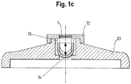
- Figure 1c shows in an advantageous embodiment, an advantageous integration of the device according to the Figure 1a , in a variant, in the housing of the filter device, preferably in a lid of a filter housing.
- this device has the Figure 1c a hydrophobic membrane 1 which may be a sterile filter at the same time, designed as a device for receiving the hydrophobic membrane 1 end member 32, which also preferably with the preferred internally cylindrical base body 33, the lid of a filter housing which is open in both directions , Is connected and this at a first end, preferably the upper end, completely completes.
- the movable sealing element in the Figure 1c Plotted in position 34 can move along the preferably cylindrical cavity in the base body 33 substantially along a preferably perpendicular axis from position 34 to position 35.
- the two positions are predetermined such that in position 35, the movable part forms an air-tight, vapor-tight and / or liquid-tight seal while being pressed against the closing element 32, and in position 34 the air-tight, vapor-tight and / or liquid-tight movable sealing element Closure under contact with the closing element 32 forms.
- the force with which the movable sealing element 32 is pressed results in position 35 from the pressure difference between the inner and outer space, as well as the buoyancy of the floating Sealing element minus the weight, in position 34, the contact pressure results from the weight and the pressure difference.
Description
- Die Erfindung betrifft eine Vorrichtung zur Entlüftung eines Filters, bevorzugt eines Hohlfaserfilters, nach dem Oberbegriff des Anspruchs 1.
- Filter werden in vielen weiten Bereichen der Industrie und in der Medizin zur Reinigung von Gasen und Flüssigkeiten eingesetzt. Die eingesetzten Filter sind dabei derart gestaltet, dass sie aus zwei Kammern bestehen, die voneinander mit einer semipermeablen Membran getrennt sind. Die semipermeable Membran ist dabei derart beschaffen, dass durch sie aus einer ersten Kammer Flüssigkeit in eine zweite Kammer gedrückt werden kann, während höhermolekulare Stoffe zurückgehalten werden.
- Ein Anwendungsgebiet von Fluidfiltern sind Verfahren zur Fluidbehandlung oder Blutbehandlung, etwa der Hämodialyse oder der Peritonealdialyse.
- Bei der Hämodialyse wird Blut in einem extrakorporalen Kreislauf kontinuierlich einem Patienten entnommen, durch einen Hämodialysator geleitet und dem Patienten wieder reinfundiert. Dabei wird ein Stoffaustausch durchgeführt, der dem der Nieren ähnlich ist. Der Hämodialysator besteht aus zwei durch eine semipermeable Membran getrennte Kammern, von denen die eine vom Blut und die andere von einer Reinigungsflüssigkeit - der Dialysierflüssigkeit - durchflossen wird. Die handelsüblichen Hämodialysatoren weisen hierfür meist Tausende von Hohlfasern auf, deren Wände die semipermeable Membran für die auszutauschenden Substanzen bilden. Das Blut wird durch den Innenraum der Hohlfasern geleitet, während die Dialysierflüssigkeit in meist gegenläufiger Richtung in den Hohlfaserzwischenraum eingespeist und abgeführt wird.
- Die Dialysierflüssigkeit weist Konzentrationen von Blutinhaltsstoffen wie Elektrolyten auf, die in etwa denen eines gesunden Menschen entsprechen, damit die entsprechenden Konzentrationen im Blut auf einem normalen Niveau gehalten werden können. Aus dem Blut zu entfernende Stoffe wie zum Beispiel Kreatinin oder Harnstoff sind in der Dialysierflüssigkeit nicht enthalten, wodurch diese allein wegen des Konzentrationsgradienten an der Membran durch Diffusion aus dem Blut entfernt werden. Mit Hilfe eines Druckgradienten wird dem Blut überschüssiges Wasser durch Konvektion beziehungsweise Ultrafiltration entzogen. Der aus Konvektion und Diffusion kombinierte Entzug wird als Diafiltration bezeichnet.
- Zur Steuerung derartiger Vorgänge werden Hämodialysegeräte eingesetzt, die zumeist auch die Zubereitung der Dialysierflüssigkeit aus Wasser und Konzentraten mit der richtigen Zusammensetzung und Temperatur sicherstellen. Bei der Hämodiafiltration wird dem Blut des Patienten während einer Hämodialysebehandlung über den Hämodialysator eine größere Menge Ultrafiltrat entzogen, die bis auf die insgesamt zu entziehende Flüssigkeitsmenge wieder durch Substitutionsflüssigkeit ersetzt wird. Bei modernen Geräten zur Behandlung des chronischen Nierenversagens wird hierfür die online aufbereitete Dialysierflüssigkeit verwendet, indem eine von dem Dialysierflüssigkeitskreislauf abzweigende Leitung mit einem oder mehreren Filterstufen versehen und mit dem extrakorporalen Blutkreislauf stromauf und/oder stromab des Hämodialysators verbunden wird. Die Zugabe der zusätzlich gefilterten Dialysierflüssigkeit in den Blutkreislauf wird als Dilution bezeichnet.
- Zu Beginn der Dialysebehandlung müssen die in den Filterstufen angeordneten Filter mit Dialysierflüssigkeit durchspült und entlüftet werden.
- Aus der
DE 4027531 C1 ist eine Anordnung bekannt, die mittels eines Hydrophobfilter an einem oberen Ende eines Hohlfaserfilters eine Entlüftung erreicht. Bei dieser Anordnung ist nachteilig, dass sich das Hydrophobfilter über den gesamten Querschnitt des Hohlfaserfilters erstreckt und somit nicht Druckstabil ist. Des Weiteren ist eine derartige Membran nachteilig bezüglich der Herstellungskosten. - Aus der
DE 3444671 A1 ist ein Verfahren bekannt, welches eine Entlüftung eines Filters mittels Sterilfilter und Hydrophobfilter erreicht. Der in zwei Kammern aufgeteilte zu entlüftende Filter hat dabei in der ersten Kammer an deren unteren Ende einen für die Zufuhr von Flüssigkeit vorgesehenen Anschluss, und am oberen Ende einen Anschluss mit einer Ausgleichskammer und dem besagten Hydrophobfilter. Die zweite Kammer hat am unteren Ende einen Anschluss, der mit dem besagten Sterilfilter verbunden ist und die für das Entlüften über dem besagten Hydrophobfilter angeordnet wird. Das Entlüften erfolgt nun derart, dass über den unteren Anschluss der ersten Kammer Flüssigkeit eingebracht wird und die in dieser Kammer befindliche Luft durch das Hydrophobfilter verdrängt. Sobald die gesamte Luft verdrängt ist, wird der Hydrophobfilter mit Flüssigkeit beaufschlagt und damit für weiteren Durchgang für Luft undurchlässig. Nun wird die Flüssigkeit durch die Membran des zu entlüftenden Filters gedrückt und beginnt die Luft in der zweiten Kammer durch das Sterilfilter zu verdrängen. Sobald im Wesentlichen keine Luft mehr durch das Sterilfilter entweicht, ist der Entlüftungsvorgang abgeschlossen. Nachteilig bei diesem Verfahren ist, dass das Sterilfilter nur einmalig verwendet werden kann. - Weiter nachteilig ist dabei, dass das Hydrophobfilter mit Flüssigkeit benetzt wird und somit die Sterilität und Druckfestigkeit fortan nicht mehr gewährleistet ist.
- Wenn die Sterilität beeinträchtigt ist besteht die unmittelbare Gefahr, dass Verunreinigungen oder Keime wie Pilze und Bakterien von der Substitutionsleitung in das Blut des Patienten übergehen.
- Auch nachteilig ist die mehrmalige notwendige manuelle Intervention von seitens des bedienenden Personals.
- Aus
WO 2006/049822 ist ein Verfahren zur Entlüftung eines Filters bekannt, bei dem der Filter aus der vertikalen Position heraus etwas geneigt wird. Damit wird erreicht, dass sich Luft am oberen Ende des Filters an der so entstandenen höchsten Stelle sammelt. Die Entlüftung kann nun über diese höchste Stelle erfolgen, wobei hier jedoch nachteilig eine manuell zu verschließende Klemme nach Entlüftung geschlossen werden muss. - Es ist bekannt, dass Hydrophobfilter Gase oder Gasgemische, insbesondere Luft und Dampf, durchlassen, nicht jedoch Flüssigkeiten und sonstige Feststoffe wie beispielsweise Bakterien und Toxine. Aufgrund dieser Eigenschaft werden Hydrophobfilter als Sterilfilter eingesetzt. Kommt die Membran des Hydrophobfilters mit Flüssigkeit in Berührung, so verliert sie die Eigenschaft der Gas- und Dampfdurchlässigkeit auch vollständig, so dass keinerlei Durchlässigkeit mehr gegeben ist. Darüber hinaus könne sich Bakterien an feuchte Stellen ansetzen und so an die feuchte Hydrophobmembran gelangen.
- In einem Dialysierflüssigkeitskreislauf mit einem Hydrophobfilter und einem diesen abschließenden Anschluss muss der Anschluss nicht notwendig verschlossen werden, da das Hydrophobfilter druckbeständig ist und während der Behandlung normalerweise einen gegenüber dem Umgebungsdruck erhöhten Druck aufweist. Es ist jedoch vorteilhaft, das Hydrophobfilter nicht während der Behandlung alleinig als Druckbarriere zu benutzen. Dies ist insbesondere deshalb nachteilig, da während der Behandlung Druckschwankungen, hervorgerufen unter anderem durch Pumpen im Dialysierflüssigkeitskreislauf, eine wechselnde Druckbelastung an der Hydrophobfiltermembran hervorrufen und das Risiko des Brechens und damit verbunden ungewollten Flüssigkeitsaustritt und Probleme der Dilution am zu behandelnden Patient nach sich ziehen kann. Des Weiteren kann eine Hydrophobmembran so ihre Wirkung als Sterilfilter verlieren, so dass während der Behandlung ein erhöhtes Risiko für eine Kontamination des blutseitigen Kreislaufs besteht.
- Der Erfindung liegt daher die Aufgabe zugrunde zumindest einen der genannten Nachteile zu überwinden sowie ein Entlüftungsventil und einen Filter mit einem zugehörigen Entlüftungsventil anzugeben, die eine automatische Entlüftung ermöglicht.
- Diese Aufgabe wird mit dem Entlüftungsventil nach Anspruch 1 gelöst.
- Vorteilhafte Weiterbildungen der Vorrichtung nach Anspruch 1 sind in den abhängigen Ansprüchen angegeben.
- Offenbart wird ein Entlüftungsventil zum Entlüften eines Filters, vorzugsweise eines Filters für eine Blutbehandlungsmaschine etwa eines Filters für einen Dialysierflüssigkeitskreislauf einer Dialysemaschine. Das Entlüftungsventil umfasst einen Hohlraum mit einer ersten und einer zweiten Öffnung und einem Dichtelement im Innern des Hohlraums zum Abdichten der ersten Öffnung in einer ersten Position und zum Abdichten der zweiten Öffnung in einer zweiten Position. Das Dichtelement ist zwischen der ersten und der zweiten Position frei beweglich so dass ein Durchfluss zwischen der ersten und der zweiten Öffnung gebildet wird, wenn das Dichtelement sich in einer Zwischenposition zwischen der ersten und der zweiten Position befindet.
- In einer Ausführungsform werden im Betrieb der Dialysemaschine und somit im Betrieb des Dialysierflüssigkeitskreislaufs eine senkrechte und eine horizontale Richtung sowie eine untere und eine obere Position vorgeben und das Dichtelement ist im Betrieb der Dialysemaschine und des Dialysierflüssigkeitskreislaufs so zwischen der oberen und der unteren Position beweglich, dass die Bewegungstrajektorie zwischen der unteren und der oberen Position eine Komponente in senkrechter Richtung aufweist. Mit anderen Worten: die erste Position ist eine untere Position und die zweite Position ist eine obere Position.
- Weiterhin vorteilhaft ist das Dichtelement als Schwimmkörper zum Schwimmen auf der Dialysierflüssigkeit ausgebildet. Auf diese Weise trägt eine Auftriebskraft mit senkrechter, d.h. nach oben gerichteter Komponente zur Abdichtung des Dichtelements in der oberen Position bei.
- In einer Ausführungsform umfasst die Oberflache des Dichtelements ein hydrophobes Material. Es kann aber auch das gesamte Dichtelement aus hydrophobem Material bestehen.
- In der Anwendung im Zusammenhang mit einer Blutbehandlung, und/ oder einer Blutbehandlungsmaschine besteht ein Vorteil der offenbarten Vorrichtung darin, dass die Handhabung und die Fehlertoleranz der Bedienung verbessert und/ oder die notwendigen manuell auszuführenden Schritte des bedienenden Personals verringert. Weiterhin sind die Kosten für die Herstellung gemindert.
-
-
Figur 1a zeigt ein Entlüftungsventil im Einklang mit der Lehre der vorliegenden Erfindung. -
Figur 1b zeigt eine weitere Ausgestaltung eines Entlüftungsventils. -
Figur 1c zeigt die Integration eines Entlüftungsventils in ein Gehäuse einer Filtervorrichtung. - Im Folgenden werden die Vorrichtung im Einklang mit der erfindungsgemäßen Lehre und vorteilhafte Weiterbildungen anhand der Abbildungen 1a, 1b und 1c näher erläutert, ohne dass die erfindungsgemäße Lehre darauf eingeschränkt sein soll.
-
Abbildung 1a zeigt ein Entlüftungsventil für einen Dialysierflüssigkeitskreislauf einer Dialysemaschine mit einer Hydrophobmembran 1, die vorteilhaft zugleich als Sterilfilter wirkt, mit einem Abschlusselement 2, das vorteilhaft als Aufnahmevorrichtung 2 für die Aufnahme der Hydrophobmembran 1 ausgebildet ist. Abschlusselement 2 ist mit dem bevorzugt innen zylindrisch geformten Körper 6, der nach beiden Richtungen hin offen ist und einen rohrförmigen Hohlraum bildet, verbunden und schließt diesen an einem ersten Ende vollständig ab. Am zweiten Ende ist der zylindrische Innenraum des Körpers 6 mittels des Abschlusselements 5 mit einer Öffnung 9, welches bevorzugt als ein scheibenförmiger Körper mit einem zentrisch axial verlaufenden angeordneten Loch ausgebildet ist, verbunden. Das Abschlusselement 5 schließt den Innenraum des Körpers 6 nach unten ab. In einer weiteren Ausgestaltung kann der Körper 6 auch bereits das Abschlusselement 5 mit ausformen. Im entstehenden Hohlraum 8 im inneren des Körpers 6 befindet sich ein beweglich angeordnetes Dichtelement 7, das so geformt ist, dass er durch Andrücken an das Abschlusselement 2 oder das Abschlusselement 5 einen gas-, dampf- und/oder flüssigkeitsdichten Verschluss bildet, wobei das Dichtelement 7 jeweils nur einen oder eines der beiden Abschlusselemente nicht jedoch beide zugleich verschließen kann. Im Betrieb der Dialysemaschine sind eine horizontale und eine vertikale Orientierung definiert, sowie eine obere Position 3 des Dichtelements 7 und eine untere Position 4 des Dichtelements 7. Im Betrieb der Dialysemaschine ist das Dichtelement 7 zwischen der unteren Position 4 und der oberen Position 3 beweglich. Die Bewegungstrajektorie zwischen der unteren Position 4 und der oberen Position 3 enthält somit zumindest eine Komponente in vertikaler Richtung. Um eine Bewegung des Dichtelements 7 entlang der Bewegungstrajektorie sicherzustellen können Führungsmittel (nicht gezeigt) vorgesehen sein. Das Dichtelement 7 ist vorzugsweise als Schwimmkörper zum Aufschwimmen auf einer Flüssigkeit ausgebildet, in der Anwendung in einem Dialysierflüssigkeitskreislauf: zum Aufschwimmen auf der Dialysierflüssigkeit. - Steigt in dem Körper 6 Flüssigkeit von unten nach oben an, so ist das Dichtelement 7 zunächst in Folge des Gewichts in der unteren Position 4 und an das Abschlusselement 5 vollständig verschließend aufliegend. Flüssigkeit und/oder das Gas und/oder der Dampf hebt anschließend das schwimmend ausgeführte Dichtelement 7 an und ermöglicht so, dass Gas durch die Membran des Hydrophobfilters 1 entweichen kann, bis das Dichtelement 7 in der Position 3 an das Abschlusselement 2 angedrückt wird und diese verschließt. Ein weiteres Austreten von Flüssigkeit, Dampf, und/oder Gas ist dann nicht mehr möglich. Bei der Ausführung des Dichtelements 7 als Schwimmkörper wirkt eine Auftriebskraft auf das Dichtelements 7, die der oberen Position 3 als Dichtkraft wirkt.
- Vorteilhaft bei dieser Anordnung ist dabei, dass ein in einem angeschlossenen Fluidkreislauf durchgeführter Druckhaltetest keine Beschädigung der Hydrophobmembran verursacht.
- Weiterhin vorteilhaft ist, dass eine kostengünstige Herstellung ermöglicht wird.
- Weiterhin vorteilhaft im Zusammenhang mit der Anwendung des Entlüftungsventils zur Entlüftung eines Filters in einem Fluidkreislauf einer Blutbehandlungsmaschine, insbesondere in einer Dialysemaschine ist es, dass durch das Verschließen des Abschlusselements 5 in der unteren Position 4 kein Eindringen von Luft während des Betriebes der Blutbehandlung infolge von Druckschwankungen hervorgerufen werden kann und dass so keine Luft durch Pumpen zurück in den Filter gelangen kann.
- Das Dichtelement 7 ist vorteilhaft aus elastischem Kunststoff ausgeführt, wobei die Oberfläche in vorteilhafter Weise aus einem hydrophoben Material besteht, oder mit diesem beschichtet ist. Damit wird erreicht, dass das Dichtelement 7 in Position 3 zusätzlich zur Auftriebskraft noch eine Kraft hervorgerufen durch die Oberflächenspannung erfährt und somit den Anpressdruck des Dichtelements 7 an die Aufnahmevorrichtung 2 und so die Dichtigkeit in Position 3 unterstützt.
- Das Gewicht des Dichtelements 7 ist vorteilhaft so gewählt, dass bei Abwesenheit von Flüssigkeit in dem Körper 6 auf Grund der Gewichtskraft des Dichtelements 7 eine zum Abdichten in der unteren Position 4 ausreichende Dichtkraft vorhanden ist.
-
Abbildung 1b zeigt eine nicht zur Erfindung gehörende alternative Ausgestaltung zu der im Zusammenhang mitFigur 1a beschriebenen Vorrichtung. Gleiche oder entsprechende Elemente sind mit gleichen Bezugszeichen wie inFigur 1a versehen, wobei auf die Beschreibung derFigur 1a Bezug genommen wird an Stelle einer Widerholung. An die Stelle des Dichtelements 7 tritt ein kugelförmiges Dichtelement 29, das sich in einem bevorzugt zylindrischen Hohlraum des Körpers 6 im Wesentlichen auf und ab bewegen kann zwischen einer unteren Position 28, vorgegeben durch das Abschlusselement 27 und einer oberen Position 24, vorgegeben durch das Abschlusselement 2 oder in einer vorteilhaften Weiterbildung durch das zusätzlich angebrachte Begrenzungselement 23. Die Hydrophobmembran 1, das Abschlusselement 2, und der bevorzugt zylindrisch ausgeführte Körper 6 entsprechen den im Zusammenhang mitFigur 1a beschriebenen Elemente. Zusätzlich weist die - Anordnung von
Figur 1b ein mit dem bevorzugt zylindrisch ausgeführten Körper 6 verbundenes Abschlusselement 27 auf. Die Abschlusselemente 2 und 23 können mit dem Körper 6 einstückig ausgeführt sein. - Ein Halteelement 25 ist zwischen dem Begrenzungselement 23 und dem Abschlusselement 27 derart angeordnet, dass, wenn sich das Dichtelement 29 in der Position 24 befindet, dieses die Öffnung in dem Begrenzungselement 23 und in dem Halteelement 25 vollständig gas-, dampf, und/oder flüssigkeitsfest verschließt und zusätzlich von dem Halteelement 25 in Position 24 gehalten wird, jedoch in der unteren Position 28 einen Durchfluss für Gase und Flüssigkeiten ausbildet. Das Halteelement 25 ist derart gestaltet, dass das Dichtelement 29 nur durch Beaufschlagung einer hinreichend großen Kraft von Position 24 nach Position 28 beziehungsweise von Position 28 nach Position 24 verschoben werden kann. Die Beaufschlagung der Kraft erfolgt vorteilhaft durch Druck, aufgebaut beispielsweise durch eine Pumpe in einem an das Entlüftungsventil abgeschlossenen Fluidkreislaufs. Bei der Entlüftung eines an das Entlüftungsventil angeschlossenen Filters wird zunächst Luft durch den Körper 6 von unten nach oben austreten und erst wenn Flüssigkeit das auf der Flüssigkeit aufschwimmende Dichtelement 9, soweit anhebt, dass es mit dem Dichtelement 25 gas- und flüssigkeitsdicht verschließt, kann über die Zufuhr weiterer Flüssigkeit der nötige Druck und damit die nötige Kraft aufgebaut werden, um das bewegliche Dichtelement 29 in Position 24 zu bewegen. Umgekehrt kann durch Erzeugung eines entsprechend hohen Unterdruckes das Dichtelement 29 von der Position 24 in die Position 28 bewegt werden und somit eine durchgängige Verbindung in dem Körper 6 hergestellt werden. Der bewegliche Dichtelement 29 und/oder das Haltelement 25 sind bevorzugt aus einem elastischen Material, beispielsweise weichem Kunststoff, Gummi oder Ähnlichem auszuführen. Der erforderliche Druck, um das Dichtelement 29 in die Position 24 zu bringen ist etwa durch die Wahl des Materials und der Abmessung des Dichtelements 29 und des Durchmessers der in dem Halteelement 25 vorgesehenen Öffnung vorteilhaft derart bemessen, dass er größer ist als die Druckschwankungen die während des Betriebs eines an das Entlüftungsventils angeschlossenen Fluidkreislaufs, etwa eines Dialysatkreislaufs einer Blutbehandlungsmaschine auftreten können. So kann ein versehentliches Öffnen verbunden mit ungewolltem Lufteintritt vermieden werden. Andererseits sollte der erforderliche Druck geringer als der maximal durch die angeschlossene Vorrichtung erzeugbare Druck sein. Damit kann auf vorteilhafte Weise erreicht werden, dass die Vorrichtung automatisch durch das Gerät ohne zusätzliche Vorrichtungen an der Gerätevorderseite bedient werden kann, wenn das Entlüftungsventil auf der Geräterückseite angeordnet ist. Weiters vorteilhaft ist, dass das Ventil wieder geöffnet werden kann und damit bei der Anwendung in einem Dialysatkreislauf einer Dialysemaschine nach der Behandlung und der Re-Infusion ein rascheres und rückstandfreieres Entleeren erfolgt.
-
Abbildung 1c zeigt in einer vorteilhaften Ausgestaltung eine vorteilhafte Integration der Vorrichtung entsprechend derAbbildung 1a , in einer Variante, in das Gehäuse der Filtervorrichtung, bevorzugt in einen Deckel eines Filtergehäuses. - In ähnlicher Weise wie in den zuvor beschriebenen Vorrichtungen, weist diese Vorrichtung der
Figur 1c eine Hydrophobmembran 1 die zugleich ein Sterilfilter sein kann, ein als Vorrichtung für die Aufnahme der Hydrophobmembran 1 ausgebildetes Abschlusselement 32, welches mit dem bevorzugt innen zylindrisch geformten Grundkörper 33, der zugleich auch bevorzugt den Deckel eines Filtergehäuses darstellt, der nach beiden Richtungen hin offen ist, verbunden ist und diesen an einem ersten Ende, bevorzugt dem oberen Ende, vollständig abschließt. Das bewegliche Dichtelement in derAbbildung 1c in Position 34 eingezeichnet, kann sich jedoch entlang des bevorzugt zylindrischen Hohlraumes in dem Grundkörper 33 im Wesentlichen entlang einer bevorzugt senkrecht verlaufenden Achse von Position 34 bis Position 35 bewegen. Die beiden Positionen sind dabei derart vorgegeben, dass in Position 35 der bewegliche Teil unter Anpressung an das Abschlusselement 32 einen luft-, dampf- und/oder flüssigkeitsdichten Verschluss bildet und in Position 34 das bewegliche Dichtelement einen luft-, dampf- und/oder flüssigkeitsdichten Verschluss unter Anpressung an das Abschlusselement 32 bildet. Die Kraft mit der der bewegliche Dichtelement 32 angepresst wird, ergibt sich in Position 35 aus der Druckdifferenz zwischen Innen- und Aussenraum, sowie der Auftriebskraft des aufschwimmenden Dichtelements abzüglich der Gewichtskraft, in Position 34 ergibt sich die Anpresskraft aus der Gewichtskraft und der Druckdifferenz.
Claims (9)
- Filter für einen Dialysierflüssigkeitskreislauf mit einer Hydrophobmembran, gekennzeichnet durch ein Entlüftungsventil zum Entlüften des Filters, umfassend einen Hohlraum (8) mit einer ersten (9) und einer zweiten Öffnung (1), und einem Dichtelement (7, 29) im Innern des Hohlraums zum Abdichten der ersten Öffnung in einer ersten Position (4, 28) und zum Abdichten der zweiten Öffnung in einer zweiten Position (3, 24), wobei das Dichtelement zwischen der ersten (4, 28) und der zweiten (4, 28) Position frei beweglich ist und wobei ein Durchfluss zwischen der ersten und der zweiten Öffnung (1) gebildet wird, wenn das Dichtelement (7, 29) sich in einer Zwischenposition zwischen der ersten (4, 28) und der zweiten (3, 24) Position befindet, wobei das Dichtelement (7, 29) derart ausgebildet ist, um in einer Flüssigkeit an der Oberfläche zu schwimmen, wobei die zweite Öffnung (1) mit der Hydrophobmembran versehen ist.
- Filter nach Anspruch 1, wobei im Betrieb des Dialysierflüssigkeitskreislaufs eine senkrechte und eine horizontale Richtung vorgegeben werden und wobei das Dichtelement (7, 29) im Betrieb des Dialysierflüssigkeitskreislaufs mit einer Bewegungskomponente in senkrechter Richtung zwischen der ersten (4, 28) zur zweiten (3, 24) Position beweglich ist.
- Filter nach Anspruch 1 oder 2, wobei eine Oberfläche des Dichtelements (7, 29) ein hydrophobes Material umfasst.
- Filter nach einem der vorangehenden Ansprüche, wobei das Dichtelement (7) eine Becherform oder die Form einer Halbkugelschale oder die Form einer Kugel aufweist.
- Filter nach Anspruch 4, wobei das Dichtelement eine Führungslippe zum Führen des Dichtelements zwischen der ersten und zweiten Position aufweist.
- Filter nach einem der vorangegangen Ansprüche, wobei das Dichtelement (29) an der zweiten Position (24) durch eine durch Druck lösbare Einrastung verschließend festgehalten wird.
- Filter nach Anspruch 6, wobei das Material des Dichtelements (29) elastische Eigenschaften aufweist.
- Filter nach einem der vorangehenden Ansprüche, wobei das Entlüftungsventil in einer Entlüftungskappe (33) des Filters integriert ist.
- Dialysierflüssigkeitskreislauf zur Zubereitung von Dialysierflüssigkeit mit einem Filter nach einem der vorangehenden Ansprüche.
Priority Applications (1)
| Application Number | Priority Date | Filing Date | Title |
|---|---|---|---|
| EP17184739.5A EP3263154B1 (de) | 2012-12-03 | 2013-11-29 | Vorrichtung zur raschen entlüftung und entleerung eines filters |
Applications Claiming Priority (3)
| Application Number | Priority Date | Filing Date | Title |
|---|---|---|---|
| US201261732628P | 2012-12-03 | 2012-12-03 | |
| DE102012023504.6A DE102012023504A1 (de) | 2012-12-03 | 2012-12-03 | Vorrichtung zur raschen Entlüftung und Entleerung eines Filters |
| PCT/EP2013/075103 WO2014086681A1 (de) | 2012-12-03 | 2013-11-29 | Vorrichtung zur raschen entlüftung und entleerung eines filters |
Related Child Applications (2)
| Application Number | Title | Priority Date | Filing Date |
|---|---|---|---|
| EP17184739.5A Division EP3263154B1 (de) | 2012-12-03 | 2013-11-29 | Vorrichtung zur raschen entlüftung und entleerung eines filters |
| EP17184739.5A Division-Into EP3263154B1 (de) | 2012-12-03 | 2013-11-29 | Vorrichtung zur raschen entlüftung und entleerung eines filters |
Publications (2)
| Publication Number | Publication Date |
|---|---|
| EP2925384A1 EP2925384A1 (de) | 2015-10-07 |
| EP2925384B1 true EP2925384B1 (de) | 2018-09-05 |
Family
ID=50725718
Family Applications (2)
| Application Number | Title | Priority Date | Filing Date |
|---|---|---|---|
| EP13798660.0A Active EP2925384B1 (de) | 2012-12-03 | 2013-11-29 | Vorrichtung zur raschen entlüftung und entleerung eines filters |
| EP17184739.5A Active EP3263154B1 (de) | 2012-12-03 | 2013-11-29 | Vorrichtung zur raschen entlüftung und entleerung eines filters |
Family Applications After (1)
| Application Number | Title | Priority Date | Filing Date |
|---|---|---|---|
| EP17184739.5A Active EP3263154B1 (de) | 2012-12-03 | 2013-11-29 | Vorrichtung zur raschen entlüftung und entleerung eines filters |
Country Status (5)
| Country | Link |
|---|---|
| US (1) | US10082222B2 (de) |
| EP (2) | EP2925384B1 (de) |
| CN (1) | CN104812423B (de) |
| DE (1) | DE102012023504A1 (de) |
| WO (1) | WO2014086681A1 (de) |
Families Citing this family (5)
| Publication number | Priority date | Publication date | Assignee | Title |
|---|---|---|---|---|
| CN105797237A (zh) * | 2016-05-12 | 2016-07-27 | 山东威高集团医用高分子制品股份有限公司 | 一种药液过滤器 |
| CN106949334A (zh) * | 2017-03-29 | 2017-07-14 | 湖州师范学院 | 一种旋钉制动保健水流调节机构 |
| JP7158167B2 (ja) * | 2018-04-06 | 2022-10-21 | 株式会社テイエルブイ | フロート式逆止弁 |
| US10914399B1 (en) | 2019-07-31 | 2021-02-09 | Jeremy Hohnbaum | System and apparatus for controlling fluid flow in drainage systems |
| DE102020118081A1 (de) | 2020-07-09 | 2022-01-13 | Dr. Ing. H.C. F. Porsche Aktiengesellschaft | Vorrichtung zur Entlüftung eines Hydrauliksystems |
Family Cites Families (15)
| Publication number | Priority date | Publication date | Assignee | Title |
|---|---|---|---|---|
| US3424184A (en) * | 1966-10-18 | 1969-01-28 | Richard Brimley | Venting antisiphon rotary plug valve with drainage means |
| US3900230A (en) * | 1974-05-13 | 1975-08-19 | Midland Ross Corp | Pneumatic brake system incorporating a double check valve |
| US4104004A (en) * | 1976-11-12 | 1978-08-01 | The De Laval Separator Company | Air eliminator for pumps |
| FR2456538A2 (fr) * | 1979-05-17 | 1980-12-12 | Boeuf Lola Le | Dispositif de filtration |
| DE3444671A1 (de) | 1984-12-07 | 1986-06-12 | Fresenius AG, 6380 Bad Homburg | Haemodiafiltrationsgeraet |
| DE8603781U1 (de) | 1986-02-13 | 1986-04-03 | Deutsche Bundesbahn, vertreten durch das Bundesbahn-Zentralamt Minden (Westf), 4950 Minden | Differenzdruckventil |
| CN2058109U (zh) * | 1989-08-16 | 1990-06-13 | 西安医科大学第一附属医院 | 氧气过滤器 |
| US4981154A (en) * | 1990-01-30 | 1991-01-01 | Hollister, Inc. | Fluid flow control device |
| CN2090280U (zh) * | 1990-06-07 | 1991-12-11 | 彭罗民 | 穿戴式血液透析滤过装置 |
| DE4027531C1 (en) | 1990-08-31 | 1991-07-25 | Fresenius Ag, 6380 Bad Homburg, De | Filter for sterilising aq. soln. e.g. dialysis liq. - where incoming liq. flows between 1st antechamber, and fibre interiors into 2nd antechamber |
| WO2006049822A1 (en) | 2004-10-28 | 2006-05-11 | Nxstage Medical, Inc | Blood treatment dialyzer/filter design to trap entrained air in a fluid circuit |
| US8444587B2 (en) * | 2007-10-01 | 2013-05-21 | Baxter International Inc. | Fluid and air handling in blood and dialysis circuits |
| US8877061B2 (en) | 2009-11-06 | 2014-11-04 | Gloria Lovell | Dialyzer with dual safety valves |
| WO2011058571A1 (en) | 2009-11-12 | 2011-05-19 | Arun Kumar Sinha | Air breather assembly with single vent and with single / twin ball valves |
| DE102010025078B4 (de) | 2010-06-25 | 2022-07-21 | Hilite Germany Gmbh | Einrichtung zum Entlüften einer von einer Druckquelle zu einem Verbraucher führenden Hydraulikleitung |
-
2012
- 2012-12-03 DE DE102012023504.6A patent/DE102012023504A1/de not_active Ceased
-
2013
- 2013-11-29 CN CN201380063187.3A patent/CN104812423B/zh active Active
- 2013-11-29 EP EP13798660.0A patent/EP2925384B1/de active Active
- 2013-11-29 EP EP17184739.5A patent/EP3263154B1/de active Active
- 2013-11-29 US US14/649,320 patent/US10082222B2/en active Active
- 2013-11-29 WO PCT/EP2013/075103 patent/WO2014086681A1/de active Application Filing
Also Published As
| Publication number | Publication date |
|---|---|
| EP2925384A1 (de) | 2015-10-07 |
| DE102012023504A1 (de) | 2014-06-05 |
| CN104812423A (zh) | 2015-07-29 |
| WO2014086681A1 (de) | 2014-06-12 |
| EP3263154B1 (de) | 2019-07-17 |
| EP3263154A1 (de) | 2018-01-03 |
| US10082222B2 (en) | 2018-09-25 |
| US20150300524A1 (en) | 2015-10-22 |
| CN104812423B (zh) | 2018-06-22 |
Similar Documents
| Publication | Publication Date | Title |
|---|---|---|
| EP2925384B1 (de) | Vorrichtung zur raschen entlüftung und entleerung eines filters | |
| DE3709432C2 (de) | ||
| EP1509260B1 (de) | Vorrichtung zur behandlung einer medizinischen flüssigkeit | |
| DE3333362C2 (de) | Peritonealdialysegerät | |
| DE3444671C2 (de) | ||
| DE102005022545B4 (de) | Verfahren zum luftfreien Füllen der Blutseite einer Hämodialysevorrichtung mit einer physiologischen Elektrolytlösung | |
| EP3061489B1 (de) | Konnektor für einen dialysator | |
| EP0407737B1 (de) | Verfahren zur Prüfung einer Hämodialysemembran | |
| DE3215003A1 (de) | Dialysevorrichtung mit verbesserter luftabscheidung | |
| EP2734287A1 (de) | Filtermodul | |
| EP3088022A1 (de) | Luftabscheider, externe funktionseinrichtung, blutkreislauf sowie behandlungsvorrichtung | |
| EP0161686B1 (de) | Verfahren zum Füllen eines Blutschlauchsystems einer Hämodialysevorrichtung mit einer physiologischen Kochsalzlösung | |
| DE102018002385A1 (de) | Entgasungsvorrichtung für Blut | |
| EP2583702B1 (de) | Verfahren zum Beenden einer Hämodialyse | |
| EP3393635B1 (de) | Verfahren und vorrichtung zur überprüfung eines dialysators auf das vorhandensein eines lecks | |
| EP0203513A2 (de) | Medizinische Beutelanordnung | |
| WO2015128474A1 (de) | Blutbehandlungskassette mit sterilisationsöffnung und zugehörigem verschluss sowie blutbehandlungsvorrichtung | |
| DE3448262C2 (en) | Method of testing sterilising filters of a haemodial filtration apparatus | |
| DE102022125964A1 (de) | Beschichtung von Hohlfasermembranen in der Medizintechnik III | |
| EP3930786A1 (de) | Dialysator und dialysevorrichtung | |
| WO2023237523A1 (de) | Beschichtung von hohlfasermembranen in der medizintechnik | |
| DE10254099B3 (de) | Hämodialysegerät | |
| WO2022171596A1 (de) | Vorrichtung für eine extrakorporale blutbehandlung | |
| WO2023094651A1 (de) | Verschlusskappe für flüssigkeitsanschlüsse eines dialysators | |
| DE20220682U1 (de) | Hämodialysegerät |
Legal Events
| Date | Code | Title | Description |
|---|---|---|---|
| PUAI | Public reference made under article 153(3) epc to a published international application that has entered the european phase |
Free format text: ORIGINAL CODE: 0009012 |
|
| 17P | Request for examination filed |
Effective date: 20150602 |
|
| AK | Designated contracting states |
Kind code of ref document: A1 Designated state(s): AL AT BE BG CH CY CZ DE DK EE ES FI FR GB GR HR HU IE IS IT LI LT LU LV MC MK MT NL NO PL PT RO RS SE SI SK SM TR |
|
| AX | Request for extension of the european patent |
Extension state: BA ME |
|
| DAX | Request for extension of the european patent (deleted) | ||
| 17Q | First examination report despatched |
Effective date: 20160623 |
|
| GRAP | Despatch of communication of intention to grant a patent |
Free format text: ORIGINAL CODE: EPIDOSNIGR1 |
|
| INTG | Intention to grant announced |
Effective date: 20180419 |
|
| GRAS | Grant fee paid |
Free format text: ORIGINAL CODE: EPIDOSNIGR3 |
|
| GRAA | (expected) grant |
Free format text: ORIGINAL CODE: 0009210 |
|
| AK | Designated contracting states |
Kind code of ref document: B1 Designated state(s): AL AT BE BG CH CY CZ DE DK EE ES FI FR GB GR HR HU IE IS IT LI LT LU LV MC MK MT NL NO PL PT RO RS SE SI SK SM TR |
|
| REG | Reference to a national code |
Ref country code: GB Ref legal event code: FG4D Free format text: NOT ENGLISH |
|
| REG | Reference to a national code |
Ref country code: CH Ref legal event code: EP |
|
| REG | Reference to a national code |
Ref country code: AT Ref legal event code: REF Ref document number: 1037118 Country of ref document: AT Kind code of ref document: T Effective date: 20180915 |
|
| REG | Reference to a national code |
Ref country code: IE Ref legal event code: FG4D Free format text: LANGUAGE OF EP DOCUMENT: GERMAN |
|
| REG | Reference to a national code |
Ref country code: DE Ref legal event code: R096 Ref document number: 502013011035 Country of ref document: DE |
|
| REG | Reference to a national code |
Ref country code: FR Ref legal event code: PLFP Year of fee payment: 6 |
|
| REG | Reference to a national code |
Ref country code: CH Ref legal event code: NV Representative=s name: DTS ZUERICH, CH |
|
| REG | Reference to a national code |
Ref country code: NL Ref legal event code: MP Effective date: 20180905 |
|
| REG | Reference to a national code |
Ref country code: LT Ref legal event code: MG4D |
|
| PG25 | Lapsed in a contracting state [announced via postgrant information from national office to epo] |
Ref country code: GR Free format text: LAPSE BECAUSE OF FAILURE TO SUBMIT A TRANSLATION OF THE DESCRIPTION OR TO PAY THE FEE WITHIN THE PRESCRIBED TIME-LIMIT Effective date: 20181206 Ref country code: NO Free format text: LAPSE BECAUSE OF FAILURE TO SUBMIT A TRANSLATION OF THE DESCRIPTION OR TO PAY THE FEE WITHIN THE PRESCRIBED TIME-LIMIT Effective date: 20181205 Ref country code: RS Free format text: LAPSE BECAUSE OF FAILURE TO SUBMIT A TRANSLATION OF THE DESCRIPTION OR TO PAY THE FEE WITHIN THE PRESCRIBED TIME-LIMIT Effective date: 20180905 Ref country code: SE Free format text: LAPSE BECAUSE OF FAILURE TO SUBMIT A TRANSLATION OF THE DESCRIPTION OR TO PAY THE FEE WITHIN THE PRESCRIBED TIME-LIMIT Effective date: 20180905 Ref country code: FI Free format text: LAPSE BECAUSE OF FAILURE TO SUBMIT A TRANSLATION OF THE DESCRIPTION OR TO PAY THE FEE WITHIN THE PRESCRIBED TIME-LIMIT Effective date: 20180905 Ref country code: LT Free format text: LAPSE BECAUSE OF FAILURE TO SUBMIT A TRANSLATION OF THE DESCRIPTION OR TO PAY THE FEE WITHIN THE PRESCRIBED TIME-LIMIT Effective date: 20180905 Ref country code: BG Free format text: LAPSE BECAUSE OF FAILURE TO SUBMIT A TRANSLATION OF THE DESCRIPTION OR TO PAY THE FEE WITHIN THE PRESCRIBED TIME-LIMIT Effective date: 20181205 |
|
| PG25 | Lapsed in a contracting state [announced via postgrant information from national office to epo] |
Ref country code: AL Free format text: LAPSE BECAUSE OF FAILURE TO SUBMIT A TRANSLATION OF THE DESCRIPTION OR TO PAY THE FEE WITHIN THE PRESCRIBED TIME-LIMIT Effective date: 20180905 Ref country code: HR Free format text: LAPSE BECAUSE OF FAILURE TO SUBMIT A TRANSLATION OF THE DESCRIPTION OR TO PAY THE FEE WITHIN THE PRESCRIBED TIME-LIMIT Effective date: 20180905 Ref country code: LV Free format text: LAPSE BECAUSE OF FAILURE TO SUBMIT A TRANSLATION OF THE DESCRIPTION OR TO PAY THE FEE WITHIN THE PRESCRIBED TIME-LIMIT Effective date: 20180905 |
|
| PG25 | Lapsed in a contracting state [announced via postgrant information from national office to epo] |
Ref country code: EE Free format text: LAPSE BECAUSE OF FAILURE TO SUBMIT A TRANSLATION OF THE DESCRIPTION OR TO PAY THE FEE WITHIN THE PRESCRIBED TIME-LIMIT Effective date: 20180905 Ref country code: PL Free format text: LAPSE BECAUSE OF FAILURE TO SUBMIT A TRANSLATION OF THE DESCRIPTION OR TO PAY THE FEE WITHIN THE PRESCRIBED TIME-LIMIT Effective date: 20180905 Ref country code: IS Free format text: LAPSE BECAUSE OF FAILURE TO SUBMIT A TRANSLATION OF THE DESCRIPTION OR TO PAY THE FEE WITHIN THE PRESCRIBED TIME-LIMIT Effective date: 20190105 Ref country code: NL Free format text: LAPSE BECAUSE OF FAILURE TO SUBMIT A TRANSLATION OF THE DESCRIPTION OR TO PAY THE FEE WITHIN THE PRESCRIBED TIME-LIMIT Effective date: 20180905 Ref country code: RO Free format text: LAPSE BECAUSE OF FAILURE TO SUBMIT A TRANSLATION OF THE DESCRIPTION OR TO PAY THE FEE WITHIN THE PRESCRIBED TIME-LIMIT Effective date: 20180905 Ref country code: CZ Free format text: LAPSE BECAUSE OF FAILURE TO SUBMIT A TRANSLATION OF THE DESCRIPTION OR TO PAY THE FEE WITHIN THE PRESCRIBED TIME-LIMIT Effective date: 20180905 Ref country code: ES Free format text: LAPSE BECAUSE OF FAILURE TO SUBMIT A TRANSLATION OF THE DESCRIPTION OR TO PAY THE FEE WITHIN THE PRESCRIBED TIME-LIMIT Effective date: 20180905 |
|
| PG25 | Lapsed in a contracting state [announced via postgrant information from national office to epo] |
Ref country code: SK Free format text: LAPSE BECAUSE OF FAILURE TO SUBMIT A TRANSLATION OF THE DESCRIPTION OR TO PAY THE FEE WITHIN THE PRESCRIBED TIME-LIMIT Effective date: 20180905 Ref country code: PT Free format text: LAPSE BECAUSE OF FAILURE TO SUBMIT A TRANSLATION OF THE DESCRIPTION OR TO PAY THE FEE WITHIN THE PRESCRIBED TIME-LIMIT Effective date: 20190105 Ref country code: SM Free format text: LAPSE BECAUSE OF FAILURE TO SUBMIT A TRANSLATION OF THE DESCRIPTION OR TO PAY THE FEE WITHIN THE PRESCRIBED TIME-LIMIT Effective date: 20180905 |
|
| REG | Reference to a national code |
Ref country code: DE Ref legal event code: R097 Ref document number: 502013011035 Country of ref document: DE |
|
| PLBE | No opposition filed within time limit |
Free format text: ORIGINAL CODE: 0009261 |
|
| STAA | Information on the status of an ep patent application or granted ep patent |
Free format text: STATUS: NO OPPOSITION FILED WITHIN TIME LIMIT |
|
| PG25 | Lapsed in a contracting state [announced via postgrant information from national office to epo] |
Ref country code: DK Free format text: LAPSE BECAUSE OF FAILURE TO SUBMIT A TRANSLATION OF THE DESCRIPTION OR TO PAY THE FEE WITHIN THE PRESCRIBED TIME-LIMIT Effective date: 20180905 Ref country code: MC Free format text: LAPSE BECAUSE OF FAILURE TO SUBMIT A TRANSLATION OF THE DESCRIPTION OR TO PAY THE FEE WITHIN THE PRESCRIBED TIME-LIMIT Effective date: 20180905 Ref country code: LU Free format text: LAPSE BECAUSE OF NON-PAYMENT OF DUE FEES Effective date: 20181129 |
|
| 26N | No opposition filed |
Effective date: 20190606 |
|
| REG | Reference to a national code |
Ref country code: BE Ref legal event code: MM Effective date: 20181130 |
|
| REG | Reference to a national code |
Ref country code: IE Ref legal event code: MM4A |
|
| PG25 | Lapsed in a contracting state [announced via postgrant information from national office to epo] |
Ref country code: SI Free format text: LAPSE BECAUSE OF FAILURE TO SUBMIT A TRANSLATION OF THE DESCRIPTION OR TO PAY THE FEE WITHIN THE PRESCRIBED TIME-LIMIT Effective date: 20180905 |
|
| PG25 | Lapsed in a contracting state [announced via postgrant information from national office to epo] |
Ref country code: IE Free format text: LAPSE BECAUSE OF NON-PAYMENT OF DUE FEES Effective date: 20181129 |
|
| PG25 | Lapsed in a contracting state [announced via postgrant information from national office to epo] |
Ref country code: BE Free format text: LAPSE BECAUSE OF NON-PAYMENT OF DUE FEES Effective date: 20181130 |
|
| REG | Reference to a national code |
Ref country code: AT Ref legal event code: MM01 Ref document number: 1037118 Country of ref document: AT Kind code of ref document: T Effective date: 20181129 |
|
| PG25 | Lapsed in a contracting state [announced via postgrant information from national office to epo] |
Ref country code: AT Free format text: LAPSE BECAUSE OF NON-PAYMENT OF DUE FEES Effective date: 20181129 Ref country code: MT Free format text: LAPSE BECAUSE OF FAILURE TO SUBMIT A TRANSLATION OF THE DESCRIPTION OR TO PAY THE FEE WITHIN THE PRESCRIBED TIME-LIMIT Effective date: 20180905 |
|
| PG25 | Lapsed in a contracting state [announced via postgrant information from national office to epo] |
Ref country code: TR Free format text: LAPSE BECAUSE OF FAILURE TO SUBMIT A TRANSLATION OF THE DESCRIPTION OR TO PAY THE FEE WITHIN THE PRESCRIBED TIME-LIMIT Effective date: 20180905 |
|
| REG | Reference to a national code |
Ref country code: CH Ref legal event code: PCAR Free format text: NEW ADDRESS: BADSTRASSE 5 POSTFACH, 8501 FRAUENFELD (CH) |
|
| PG25 | Lapsed in a contracting state [announced via postgrant information from national office to epo] |
Ref country code: CY Free format text: LAPSE BECAUSE OF FAILURE TO SUBMIT A TRANSLATION OF THE DESCRIPTION OR TO PAY THE FEE WITHIN THE PRESCRIBED TIME-LIMIT Effective date: 20180905 Ref country code: HU Free format text: LAPSE BECAUSE OF FAILURE TO SUBMIT A TRANSLATION OF THE DESCRIPTION OR TO PAY THE FEE WITHIN THE PRESCRIBED TIME-LIMIT; INVALID AB INITIO Effective date: 20131129 Ref country code: MK Free format text: LAPSE BECAUSE OF NON-PAYMENT OF DUE FEES Effective date: 20180905 |
|
| REG | Reference to a national code |
Ref country code: CH Ref legal event code: PCAR Free format text: NEW ADDRESS: BAHNHOFSTRASSE 100, 8001 ZUERICH (CH) |
|
| PGFP | Annual fee paid to national office [announced via postgrant information from national office to epo] |
Ref country code: FR Payment date: 20221021 Year of fee payment: 10 |
|
| PGFP | Annual fee paid to national office [announced via postgrant information from national office to epo] |
Ref country code: GB Payment date: 20221021 Year of fee payment: 10 |
|
| PGFP | Annual fee paid to national office [announced via postgrant information from national office to epo] |
Ref country code: CH Payment date: 20221201 Year of fee payment: 10 |
|
| P01 | Opt-out of the competence of the unified patent court (upc) registered |
Effective date: 20230602 |
|
| PGFP | Annual fee paid to national office [announced via postgrant information from national office to epo] |
Ref country code: IT Payment date: 20231019 Year of fee payment: 11 Ref country code: DE Payment date: 20231130 Year of fee payment: 11 |