EP2924927B1 - Techniques pour l'agrégation de ressources de routage matérielles dans un système de réseau à processeur multi-paquet - Google Patents
Techniques pour l'agrégation de ressources de routage matérielles dans un système de réseau à processeur multi-paquet Download PDFInfo
- Publication number
- EP2924927B1 EP2924927B1 EP15000834.0A EP15000834A EP2924927B1 EP 2924927 B1 EP2924927 B1 EP 2924927B1 EP 15000834 A EP15000834 A EP 15000834A EP 2924927 B1 EP2924927 B1 EP 2924927B1
- Authority
- EP
- European Patent Office
- Prior art keywords
- route
- routing
- routing table
- entry
- subset
- Prior art date
- Legal status (The legal status is an assumption and is not a legal conclusion. Google has not performed a legal analysis and makes no representation as to the accuracy of the status listed.)
- Active
Links
- 238000000034 method Methods 0.000 title claims description 34
- 230000006855 networking Effects 0.000 title description 12
- 230000004931 aggregating effect Effects 0.000 title description 2
- 230000009471 action Effects 0.000 claims description 5
- 238000000638 solvent extraction Methods 0.000 claims description 5
- 230000008878 coupling Effects 0.000 claims 1
- 238000010168 coupling process Methods 0.000 claims 1
- 238000005859 coupling reaction Methods 0.000 claims 1
- 238000013459 approach Methods 0.000 description 15
- 230000008569 process Effects 0.000 description 11
- 230000004048 modification Effects 0.000 description 7
- 238000012986 modification Methods 0.000 description 7
- 238000012545 processing Methods 0.000 description 7
- 238000007792 addition Methods 0.000 description 6
- 230000006870 function Effects 0.000 description 4
- 238000009434 installation Methods 0.000 description 4
- 238000012217 deletion Methods 0.000 description 3
- 230000037430 deletion Effects 0.000 description 3
- 238000013461 design Methods 0.000 description 3
- 239000004744 fabric Substances 0.000 description 3
- 101100269850 Caenorhabditis elegans mask-1 gene Proteins 0.000 description 2
- 230000002776 aggregation Effects 0.000 description 2
- 238000004220 aggregation Methods 0.000 description 2
- 230000002411 adverse Effects 0.000 description 1
- 230000006835 compression Effects 0.000 description 1
- 238000007906 compression Methods 0.000 description 1
- 239000000470 constituent Substances 0.000 description 1
- 230000001419 dependent effect Effects 0.000 description 1
- 238000007689 inspection Methods 0.000 description 1
- 238000005457 optimization Methods 0.000 description 1
- 238000005192 partition Methods 0.000 description 1
- 230000010076 replication Effects 0.000 description 1
- 230000003362 replicative effect Effects 0.000 description 1
- 230000004044 response Effects 0.000 description 1
- 229910052710 silicon Inorganic materials 0.000 description 1
- 239000010703 silicon Substances 0.000 description 1
- 230000001360 synchronised effect Effects 0.000 description 1
Images


Classifications
-
- H—ELECTRICITY
- H04—ELECTRIC COMMUNICATION TECHNIQUE
- H04L—TRANSMISSION OF DIGITAL INFORMATION, e.g. TELEGRAPHIC COMMUNICATION
- H04L45/00—Routing or path finding of packets in data switching networks
- H04L45/56—Routing software
- H04L45/563—Software download or update
-
- H—ELECTRICITY
- H04—ELECTRIC COMMUNICATION TECHNIQUE
- H04L—TRANSMISSION OF DIGITAL INFORMATION, e.g. TELEGRAPHIC COMMUNICATION
- H04L45/00—Routing or path finding of packets in data switching networks
- H04L45/74—Address processing for routing
- H04L45/745—Address table lookup; Address filtering
- H04L45/748—Address table lookup; Address filtering using longest matching prefix
-
- H—ELECTRICITY
- H04—ELECTRIC COMMUNICATION TECHNIQUE
- H04L—TRANSMISSION OF DIGITAL INFORMATION, e.g. TELEGRAPHIC COMMUNICATION
- H04L45/00—Routing or path finding of packets in data switching networks
- H04L45/20—Hop count for routing purposes, e.g. TTL
Definitions
- a router is a network device that interconnects multiple networks and forwards data packets between the networks (a process referred to as Layer 3, or L3, routing).
- L3 routing To determine the best path to use in forwarding an ingress packet, a router examines the destination IP address of the packet and compares the destination IP address to routing entries in a routing table. Each routing entry corresponds to a subnet route (e.g., 192.168.2.0/24) or a host route (e.g., 192.168.2.129/32). If the destination IP address matches the subnet/host route of a particular routing entry, the router forwards the packet out of an egress port to a next hop address specified by the entry, thereby sending the packet towards its destination.
- a subnet route e.g., 192.168.2.0/2
- a host route e.g., 192.168.2.129/32
- the destination IP address of an ingress packet may match multiple routing entries corresponding to multiple subnet/host routes.
- the IP address 192.168.2.129 matches subnet routes 192.168.2.128/26 and 192.168.2.0/24, as well as host route 192.168.2.129/32.
- the router can perform its selection via longest prefix match (LPM), which means that the router will select the matched routing entry with the highest subnet mask (i.e., the most specific entry).
- LPM longest prefix match
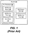
- FIG. 1 depicts an exemplary router 100 that includes a management CPU 102, a software (SW) routing table 104, and a packet processor 106 comprising a hardware (HW) routing engine 108, a HW routing table 110, and data ports 112.
- SW routing table 104 is implemented using a data structure that is stored in a random access memory accessible by management CPU 102 (not shown).
- SW routing table 104 contains all of the subnet/host routes known to router 100, such as statically configured routes and routes that are dynamically learned from routing protocols (e.g., RIP, OSPF or BGP).
- HW routing table 110 is implemented using a hardware-based memory component, such as a ternary content-addressable memory (TCAM) or other similar associative memory. Due to its specialized hardware design, HW routing table 110 can enable faster table lookups that SW routing table 104, but is limited in size. Thus, HW routing table 110 typically includes a subset of the routing entries in SW routing table 104.
- TCAM ternary content-addressable memory
- HW routing engine 108 of packet processor 106 When an ingress packet is received at router 100, HW routing engine 108 of packet processor 106 first looks for a LPM match for the packet's destination IP address in HW routing table 110. As mentioned above, HW routing engine 108 can perform this lookup very quickly (e.g., at line rate) because of table 110's hardware design. If a match is found, HW routing engine 108 forwards the packet to the next hop specified in the matched entry, without involving management CPU 102. If a match is not found, HW routing engine 108 takes a predefined action, such as dropping the packet or sending it to management CPU 102. If sent to management CPU 102, CPU 102 can perform additional inspection/processing to determine how the packet should be forwarded (such as performing a lookup in SW routing table 104).
- FIG. 2 depicts an exemplary routing trie 200 that may be used to represent SW routing table 104 of FIG. 1 .
- routing trie 200 includes both branch nodes (denoted by the unmarked circles) and route nodes (denoted by the circles marked with "R").
- Each branch node corresponds to a "fork” in routing trie 200, and thus forms the root of a sub-trie.
- Each route node corresponds to a routing entry in SW routing table 104.
- each node (whether branch or route) is associated with an IP address prefix. There are generally two rules regarding how the nodes of a routing trie may be positioned:
- routing trie for the table will contain three nodes: two route nodes (one for each of the two routes), and a root node that is a branch node associated with prefix 010/3 (because its two child nodes differ starting from the 4th bit). Note that if a new route 010/3 is added, the routing trie will still contain three nodes-the branch node associated with prefix 010/3 will become a route node.
- router 100 of FIG. 1 is depicted as a standalone device with a single packet processor and a single HW routing table, some routers are implemented as a system of interconnected devices/modules, where each device/module incorporates a separate packet processor (with a separate HW routing table). Such systems are referred to herein as "multi-packet processor” (MPP) networking systems.
- MPP multi-packet processor
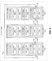
- FIG. 3 depicts a stacking system 300 (also known as a "stack"), which is one type of MPP networking system.
- stacking system 300 comprises a number of stackable switches 302(1)-302(3) that are interconnected via stacking ports 314(1)-314(3).
- Each stackable switch 302(1)-302(3) includes components that are similar to router 100 of FIG. 1 , such as management CPU 304(1)-304(3), SW routing table 306(1)-306(3), packet processor 308(1)-308(3), HW routing engine 310(1)-310(3), HW routing table 312(1)-312(3), and data ports 316(1)-316(3).
- stackable switches 302(1)-302(3) of system 300 can act in concert as a single, logical switch/router.
- stackable switch 302(1) can receive a packet on an ingress data port 316(1), perform a lookup (via HW routing engine 310(1)) into its local HW routing table 312(1), and determine based on the lookup that the packet should be forwarded out of, e.g., an egress data port 316(3) of stackable switch 302(3) in order to reach its next hop destination.
- Stackable switch 302(1) can then send the packet over stacking link 318 to stackable switch 302(3), thereby allowing switch 302(3) to forward the packet out of the appropriate egress data port.
- FIG. 4 depicts a chassis system 400, which is another type of MPP networking system.
- Chassis system 400 includes a management module 402 and a number of I/O modules 410(1)-410(3) that are interconnected via an internal switch fabric 408.
- Management module 402 includes a management CPU 404 and a SW routing table 406 that are similar to management CPU 102 and SW routing table 104 of router 100 of FIG. 1 .
- each I/O module 410(1)-410(3) includes a packet processor 412(1)-412(3), a HW routing engine 414(1)-414(3), a HW routing table 416(1)-416(3), and data ports 418(1)-418(3) that are similar to components 106-112 of router 100 of FIG. 1 .
- I/O modules 410(1)-410(3) can act in concert to carry out various data plane functions, including L3 routing, for chassis system 400.
- I/O module 410(1) can receive a packet on an ingress data port 418(1), perform a lookup (via HW routing engine 414(1)) into its local HW routing table 416(1), and determine based on the lookup that the packet should be forwarded out of, e.g., an egress data port 418(2) of I/O module 410(2) in order to reach its next hop destination.
- I/O module 410(1) can then send the packet over switch fabric 408 to I/O module 410(2), thereby allowing I/O module 410(2) to forward the packet out of the appropriate egress data port.
- One inefficiency with performing L3 routing in a MPP networking system like stacking system 300 or chassis system 400 as described above pertains to the way in which the multiple HW routing tables of the system are utilized.
- the multiple HW routing tables of the system are utilized.
- the same set of routing entries are replicated in the HW routing table of every packet processor.
- the HW routing table capacity of the system is constrained by the size of the smallest HW routing table. For instance, in stacking system 300, assume that HW routing table 312(1) supports 16K entries while HW routing tables 312(2) and 312(3) support 32K entries each.
- every HW routing table 312(1)-312(3) will be limited to holding a maximum of 16K entries (since additional entries beyond 16K cannot be replicated in table 312(1)). This means that a significant percentage of the system's HW routing resources (e.g., 16K entries in tables 312(2) and 312(3) respectively) will go unused. This also means that the HW routing table capacity of the system cannot scale upward as additional switches are added.
- T-B PEI ET AL "Putting routing in silicon", IEEE NETWORK, IEEE SERVICE CENTER, NEW YORK, NY, US, vol. 6, no.
- HSIAO YI-MAO ET AL "A high-troughput and high-capacity IPv6 routing lookup system", COMPUTER NETWORKS, ELSEVIER SCIENCE PUBLISHERS B.V., AMSTERDAM, NL, vol. 57, no.
- the system is a cache-centric, hash-based architecture that contains a routing lookup application specific integrated circuit (ASIC) and a memory set.
- a hash function is used to reduce lookup time for the routing table and ternary content addressable memory (TCAM) resolves the collision problem.
- the problem relates to improving the routing of network packets.
- This problem is solved by the subject-matter of the independent claims. Preferred embodiments are defined in the dependent claims.
- the present disclosure describes techniques for aggregating HW routing resources in a MPP networking system, such that the system is no longer limited by the capacity of the system's smallest HW routing table.
- this can be achieved by dividing the routing entries in the system's SW routing table (represented as a routing trie) into a number of route subsets, assigning each route subset to one or more devices/modules in the system, and installing the route subsets that are assigned to a particular device/module in the local HW routing table of that device/module (without installing the other route subsets).
- the routing entries in the SW routing table can be effectively split across all of the HW routing tables in the system, rather than being replicated in each one.
- the system can also install, in the HW routing table of each device/module, one or more special routing entries (referred to herein as "redirection entries") for routes that are assigned to remote devices/modules. These redirection entries can point to the remote device/module as the next hop.
- redirection entries can point to the remote device/module as the next hop.
- the device/module can perform a first L3 lookup to determine whether a routing entry that matches the packet's destination IP address is installed in the device/module's local HW routing table. If a matching routing entry is found, the device/module can cause the packet to be forwarded out of an egress data port of the system based on the entry.
- the L3 lookup can match the redirection entry noted above that identifies the remote device/module as the next hop. This, in turn, can cause the device/module to forward the packet to the remote device/module over an intra-system link (e.g., a stacking link in the case of a stacking system, or an internal switch fabric link in the case of a chassis system).
- an intra-system link e.g., a stacking link in the case of a stacking system, or an internal switch fabric link in the case of a chassis system.
- the remote device/module Upon receiving the forwarded packet, the remote device/module can perform a second L3 lookup into its HW routing table, which will include a locally installed routing entry matching the destination IP address of the packet. The remote device/module can then forward, based on the locally installed routing entry, the packet out of an appropriate egress data port towards its destination.
- the foregoing approach will not adversely affect the system's routing performance in a significant manner since an ingress packet is processed for routing at most twice (e.g., a first time for the L3 lookup at the ingress device/module and a second time for the L3 lookup at the remote device/module, if necessary).
- the assignments of route subsets to devices/modules can be implemented using a novel ownership model where each route subset is associated with an "owner set" including between zero and N owners (where N is the total number of devices/modules in the system, and where an owner set with zero owners indicates that associated routes should be installed to all devices/modules).
- this ownership model is advantageous because it supports redundancy (i.e., ownership of a routing entry by multiple devices/modules) and simplifies route re-assignments for load balancing purposes.
- references to "stacks” or “stacking systems” can be construed as encompassing generalized MPP systems comprising multiple devices or modules, and references to “switches” or “stackable switches” can be construed as encompassing generalized devices/modules within an MPP system.
- FIG. 5 depicts a stacking system 500 that supports HW routing table aggregation according to an embodiment.
- stacking system 500 comprises a number of stackable switches 502(1)-502(N), each of which includes certain components that are similar to the components of stackable switches 302(1)-302(3) of FIG. 3 (e.g., management CPU 304(1)-304(N), SW routing table 306(1)-306(N), packet processor 308(1)-308(N), HW routing engine 310(1)-310(N), HW routing table 312(1)-312(N), stacking ports 314(1)-314(N), and data ports 316(1)-316(N)).
- stackable switches 502(1)-502(N) are depicted as forming a ring topology, it should be appreciated that other types of topologies (e.g., linear, star, arbitrary mesh, etc.) are possible.
- stackable switch 502(2) is designated as the master switch of stacking system 500 (denoted by the letter "M"), which means that switch 502(2) serves as the point of user contact for all management functions of system 500.
- master switch 502(2) can accept and process user commands directed to the overall configuration of stacking system 500.
- Master switch 502(2) can also communicate with the non-master switches of stacking system 500 as needed in order to propagate various types of management commands and data to those switches.
- one inefficiency with performing L3 routing in a MPP networking system like stacking system 500 is that the same routing entries are typically replicated in each HW routing table of the system.
- This replication means that the HW routing table capacity of the stacking system is limited by the size of the smallest HW routing table, regardless of the size of the other HW routing tables or the total number of HW routing tables in the system.
- each stackable switch 502(1)-502(N) of FIG. 5 includes a novel route division component 504(1)-504(N), a novel route assignment component 506(1)-506(N), and a novel route programming component 508(1)-508(N) (alternatively, only master switch 502(2) may include these components, which is described below).
- components 504(1)-504(N), 506(1)-506(N), and 508(1)-508(N) can be implemented as software that is executed by respective management CPUs 304(1)-304(N) and stored in an associated memory (not shown). In other embodiments, one or more of these components can be implemented partially or entirely in hardware.
- route division components 504(1)-504(N), route assignment components 506(1)-506(N), and route programming components 508(1)-508(N) can work in concert to distribute the routing entries in stacking system 500's SW routing table across HW routing tables 312(1)-312(N), instead of replicating the entries in each HW routing table.
- route division components 504(1)-504(N) can first divide the routing entries in the SW routing table into a number of route subsets.
- Route assignment components 506(1)-506(N) can subsequently assign each of the route subsets to one or more stackable switches 502(1)-502(N), and route programming components 508(1)-508(N) can install the routes in each route subset into the HW routing table(s) of the stackable switch(es) to which the route subset is assigned.
- route programming components 508(1)-508(N) can install "redirection entries" in each HW routing table 312(1)-312(N) for those routing entries that are not installed locally (i.e., are only installed in the HW routing tables of other, "remote" switches in the system). These redirection entries can point to the remote switches as the next hop, thereby allowing the host switch to know where to send packets that match those entries.
- HW routing engines 310(1)-310(N) of stackable switches 502(1)-502(N) can forward incoming packets in a distributed manner using the routing entries and redirection entries that have been installed in HW routing tables 312(1)-312(N) as mentioned above. For example, if a particular HW routing engine 310(X) finds a matching routing entry (using LPM) for an ingress packet in its local HW routing table 312(X), HW routing engine 310(X) can cause the packet to be forwarded out of an egress data port of stacking system 500 based on the routing entry.
- HW routing engine 310(X) can forward, based on the redirection entry, the packet to another stackable switch of stacking system 500 (e.g., "remote" switch 502(Y)) that does have an appropriate routing entry in its HW routing table for the packet.
- HW routing engine 310(Y) of remote switch 502(Y) can then match the packet against the routing entry in its local HW routing table 312(Y) and forward the packet out of an egress data port towards its destination. In this way, stacking system 500 can correctly route packets that are received at any member switch, without requiring the same routing entries to be replicated in the HW routing table of each switch.
- route division components 504(1)-504(N), route assignment components 506(1)-506(N), route programming components 508(1)-508(N), and HW routing engines 310(1)-310(N) are presented in the sections that follow.
- FIG. 6 depicts a high-level flowchart 600 that can be performed by components 504(1)-504(N), 506(1)-506(N), and 508(1)-508(N) of FIG. 5 for distributing the routing entries in stacking system 500's SW routing table among HW routing tables 312(1)-312(N) according to an embodiment.
- flowchart 600 can be performed during an initialization phase of stacking system 500 before the system begins accepting data traffic for forwarding/routing.
- flowchart 600 (and the other flowcharts in the present disclosure) assumes: (1) SW routing tables 306(1)-306(N) of FIG. 5 are synchronized across stackable switches 502(1)-502(N); and (2) the flowchart steps are performed independently by the route division, assignment, and/or programming components of each switch 502(1)-502(N). This is referred to as a "distributed" approach.
- the steps of flowchart 600 can be performed solely by the route division, assignment, and/or programming components of the master switch in stacking system 500 (i.e., master switch 502(2)).
- master switch 502(2) i.e., master switch 502(2).
- the master switch can determine how to divide, assign, and install routes for each stackable switch in the stacking system, and can simply provide each non-master switch a list of routing entries to be installed in its local HW routing table.
- This centralized approach also obviates the need for synchronizing the SW routing table across switches-only a single copy of the SW routing table needs to be maintained by the master switch.
- the distributed approach should generate the same results (i.e., the same route installations in HW routing tables 312(1)-312(N)) as the centralized approach.
- route division component 504(X) of each stackable switch 502(X) can first divide the routing entries in its SW routing table 306(X) into a number of route subsets, where each route subset includes one or more routing entries.
- the SW routing table can be represented/maintained as a trie data structure (i.e., a routing trie). Accordingly, in these embodiments, dividing the SW routing table into routing subsets can comprise partitioning the route nodes of the routing trie.
- the number of route subsets created at block 602 is not limited by the number of stackable switches in stacking system 500.
- the SW routing table can be divided into P route subsets, where P is less than, equal to, or greater than N.
- route division component 504(X) can divide the SW routing table such that each of the P subsets comprises approximately Q/N entries.
- route assignment component 506(X) can receive the route subsets created by route division component 504(X) and can assign each route subset to an "owner set" comprising zero or more of stackable switches 502(1)-502(N). In this manner, route assignment component 506(X) can determine which subsets should be installed to which switches/HW routing tables of stacking system 500.
- the owner sets can be non-exclusive-in other words, two different owner sets (for two different route subsets) can include the same stackable switch, or "owner.” Further if an owner set includes zero owners, that indicates the route subset assigned to that owner set can be installed into the HW routing table of every stackable switch in the stacking system.
- routes with prefix length equal to or less than 8 can be assigned to an empty owner set (and thus be assigned to every stackable switch).
- this ownership model allows for relatively simple load balancing, which is typically needed/desired when 1) a stackable switch joins or leaves the stacking system, or 2) a stackable switch begins running out of free space in its HW routing table due to route additions. For instance, when routing entries need to be offloaded from the HW routing table of a particular stackable switch, the owner sets can simply be modified to re-shuffle route subset assignments, rather than re-dividing the SW routing table/trie. This load balancing process is described in further detail in Section 5.3 below.
- route programming component 508(X) of each stackable switch 502(X) can install the routing entries in the route subsets owned by switch 502(X) into its local HW routing table 312(X) (block 606).
- route programming component 508(X) can also install one or more redirection entries that correspond to routing entries installed on other stackable switches (i.e., remote switches) in stacking system 500.
- Each of these redirection entries can include, as its next hop address, the identity/address of the remote switch.
- stackable switch 502(X) can know where to forward an ingress packet for further routing if it's local HW routing table 312(X) does not include an actual routing entry matching the destination IP address of the packet.
- FIG. 7 depicts a flowchart 700 that provides additional details regarding how route programming component 508(X) can install routing and redirection entries into HW routing table 312(X) according to an embodiment.
- Flowchart 700 assumes that HW routing table 312(X) is initially empty, and thus can be carried out during an initialization phase of stacking system 500 (as noted above) or when stackable switch 502(X) newly joins stacking system 500.
- route programming component 508(X) can enter a loop for each route node R in SW routing table 306(X), which is represented as a routing trie.
- loop 702 can be implemented, such via a pre-order (i.e., parent first) or post-order (i.e., children first) traversal of the SW routing trie.
- the particular traversal method chosen may depend on the hardware design of HW routing table 312(X) (e.g., some TCAMs require a particular traversal order between child and parent nodes).
- route programming component 508(X) can first check if R has no owner (i.e., is assigned to an owner set with zero owners, which means the route is assigned to every stackable switch), or stackable switch 502(X) is in R's owner set. If so, route programming component 508(X) can install a routing entry for R into HW routing table 312(X) with an action to forward packets to R's next hop address (block 706), and can proceed to the end of the loop iteration (block 712).
- route programming component 508(X) can proceed to check whether R and a parent route node in the SW routing trie share a common owner (block 708).
- parent route node refers to the closest ancestor node in the SW routing trie that is a route node. This may not be the direct parent node of R in the trie if the direct parent node is a branch node.
- route programming component 508(X) can install a redirection entry for R into HW routing table 312(X) with an action to forward packets to a stackable switch in R's owner set (block 710).
- this redirection entry is different from the routing entry installed at block 706 because the redirection entry will simply cause stackable switch 502(X) to forward, via one or more stacking links, matching packets to the route owner for further L3 processing, rather than out of an egress data port of stacking system 500.
- route programming component 508(X) may determine at block 710 that R has multiple owners. In this scenario, route programming component 508(X) can select an owner at random for inclusion as the next hop in the redirection entry. Alternatively, route programming component 508(X) can select an owner based on one or more criteria for, e.g., optimization purposes. For example, the criteria can include shortest path (i.e., least hop count), maximum stacking port bandwidth, and/or the like.
- the current loop iteration can end (block 712) and route programming component 508(X) can return to block 702 to process additional route nodes in the SW routing trie (until the entire trie has been traversed).
- flowchart 700 is illustrative and various modifications/alternative implementations are possible.
- flowchart 700 can be modified to reduce the number of entries installed in HW routing table 312(X), thereby achieving "hardware compression.” This can involve, e.g., qualifying the routing entry installation performed at block 706 such that, if R's next hop is equal to its parent route node's next hop, the routing entry is not installed (since the parent's routing entry should cover R).
- FIGS. 8A and 8B depict a flowchart 800 can be performed by HW routing engine 310(X) of a particular stackable switch 502(X) (in conjunction with HW routing engine 310(Y) of a remote stackable switch 502(Y)) for routing an ingress packet according to an embodiment.
- HW routing engine 310(X) can receive an ingress packet at a data port 316(X) of stackable switch 502(X). HW routing engine 310(X) can then extract the destination IP address of the packet (block 804) and perform a L3 lookup of the destination IP address in local HW routing table 312(X) using longest prefix match (LPM) (block 806).
- LPM longest prefix match
- HW routing engine 310(X) can determine whether the LPM matched entry in HW routing table 312(X) is a routing entry (i.e., an entry installed per block 706 of FIG. 7 ) or a redirection entry (i.e., an entry installed per block 710 of FIG. 7 ). If the LPM matched entry is a routing entry, HW routing engine 310(X) can cause the packet to be forwarded out of an egress data port 316(X) of stackable switch 502(X) (or another stackable switch of stacking system 500) towards a next hop identified by the routing entry (block 810).
- This forwarding can include, e.g., decrementing a time-to-live (TTL) field of the packet, replacing the destination MAC address of the packet with the next hop's MAC address, and replacing the source MAC address of the packet with the MAC address of stackable switch 502(X).
- TTL time-to-live
- HW routing engine 310(X) can forward the packet out of a stacking port 314(X) of stackable switch 502(X) towards the remote stackable switch identified as the next hop within the redirection entry (e.g., switch 502(Y)) (block 812).
- the forwarding at block 812 typically will not include any modifications to the L2 or L3 headers of the packet.
- Flowchart 800 can then proceed to FIG. 8B , which is carried out by HW routing engine 310(Y) of remote switch 502(Y).
- HW routing engine 310(Y) can receive the forwarded packet at a stacking port 314(Y) and can extract the destination IP address of the packet. HW routing engine 310(Y) can then perform a second L3 lookup of the destination IP address in local HW routing table 312(Y) using LPM (block 818). Generally speaking, this second L3 lookup will result in a match with an actual routing entry for the packet, since stackable switch 502(Y) is in the owner set of the route subset comprising the packet's route.
- HW routing engine 310(Y) can take a default action, such as dropping the packet or trapping it to management CPU 304(Y).
- HW routing engine 310(Y) can cause the packet to be forwarded out of an egress data port 316(Y) of stackable switch 502(Y) towards a next hop identified by the matched routing entry (block 820).
- the forwarding at block 820 will generally include the same packet modifications described with respect to block 810 of FIG. 8A .
- FIG. 9 depicts an example packet flow based on flowchart 800 according to an embodiment.
- stackable switch 502(1) of stacking system 500 receives an ingress packet on a data port.
- the HW routing engine of stackable switch 502(1) performs a first L3 lookup in its local HW routing table to determine where to forward the packet based on the packet's destination IP address (step (2), reference numeral 904)).
- step (1) of flow 900 reference numeral 902
- stackable switch 502(1) of stacking system 500 receives an ingress packet on a data port.
- the HW routing engine of stackable switch 502(1) performs a first L3 lookup in its local HW routing table to determine where to forward the packet based on the packet's destination IP address (step (2), reference numeral 904)).
- stackable switch 502(1) would be able to forward the packet to an appropriate egress switch/port of stacking system 500.
- the real routing entry for the packet is installed on stackable switch 502(2) (i.e., the route owner).
- the HW routing engine of stackable switch 502(1) detects a match with a redirection entry that identifies stackable switch 502(2) as the next hop, and forwards the packet to switch 502(2) over a stacking link (step (3), reference numeral 906).
- the HW routing engine of stackable switch 502(2) receives the forwarded packet and determines (based on, e.g., a special stack tag affixed to the packet) that it needs to perform a second L3 lookup for the packet in its local HW routing table. Based on this second L3 lookup, the HW routing engine of stackable switch 502(2) matches the actual routing entry for the packet's destination IP address and determines the egress switch/port for forwarding the packet out of stacking system 500.
- Stackable switch 502(2) then forwards the packet over one or more stacking links to the egress switch (in this case, stackable switch 502(N)) (step (5), reference numeral 910), which subsequently sends the packet out of an appropriate egress data port to the next hop destination (step (6), reference numeral 912).
- each HW routing table 312(1)-312(N) may occasionally need to be updated/modified for various reasons. There are generally three scenarios to consider:
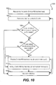
- FIG. 10 depicts a flowchart 1000 that can be performed by a route programming component 508(X) for implementing such a removal/adjustment process according to an embodiment. Note that flowchart 1000 only needs to be performed by the stackable switches of stacking system 500 that are owners of the route to be deleted.
- route programming component 508(X) can remove the routing entry to be deleted from the SW routing trie (i.e., entry B) from HW routing table 312(X). Route programming component 508(X) can then enter a loop for each direct child route node (i.e., C) of B in the SW routing trie (block 1004).
- "direct child route" C of a route node B is a route node in the sub-trie of the SW routing trie that is rooted by B, where there are no route nodes between B and C.
- R1, R3, and R4 are direct child routes of R2.
- route programming component 508(X) can traverse all of the direct child routes of B via a pre-order traversal of the sub-trie rooted by B. For instance, the following is a pseudo code listing of an exemplary recursive function for performing this pre-order traversal.
- the "node" input parameter is the root node of the sub-trie to be traversed.
- route programming component 508(X) can first check whether C has no owner or stackable switch 502(X) is C's owner (block 1006). If so, route programming component 508(X) can determine that a routing entry for C is installed in HW routing table 312(X) and that no changes are needed for the installed entry. Accordingly, route programming component 508(X) can proceed to the end of the current loop iteration (block 1014).
- route programming component 508(X) can move on to checking whether C and a parent route node of B (i.e., A) share a common owner (block 1008). If so, route programming component 508(X) can remove the routing entry for C from HW routing table 312(X) (if such an entry is already installed), since the HW entry for A will cover C (1010). Route programming component 508(X) can then proceed to the end of the current loop iteration (block 1014).
- route programming component 508(X) determines that C and A do not share a common owner at block 1008
- route programming component 508(X) can install a routing entry for C into HW routing table 312(X) (if such an entry is not already installed), since the removed entry for B was previously used to cover C (block 1012).
- This installation logic is similar to blocks 708 and 710 of FIG. 7 (in the context of block 708 of FIG. 7 , the "parent route node" is B's parent route because B is to be removed).
- the current loop iteration can end (block 1014) and route programming component 508(X) can return to block 1004 to process additional direct child routes for B (until all of the direct child routes have been traversed).
- flowchart 1000 is illustrative and various modifications/alternative implementations are possible.
- the master switch of stacking system 500 can execute flowchart 700 for each stackable switch that has route B installed in HW.
- flowchart 700 can be optimized such that the master switch runs it only once (e.g., the algorithm can loop through all stackable switches before block 1006).
- the algorithm can loop through all stackable switches before block 1006.
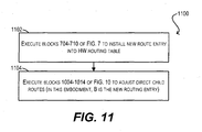
- FIG. 11 depicts a flowchart 1100 that can be performed by route programming component 508(X) of each owner switch 502(X) for performing this installation according to an embodiment.
- route programming component 508(X) can execute blocks 704-710 of FIG. 7 (i.e., the initial programming flow) in order to install the new route into HW routing table 312(X). Then, at block 1104, route programming component 508(X) can execute blocks 1004-1014 of FIG. 10 in order to adjust the direct child routes of the newly added route.
- route B of FIG. 10 can correspond to the new route and route C of FIG. 10 can correspond to a direct child route of the new route.
- block 1008 of FIG. 10 should be modified to read "C and B have a common owner?" rather than "C and parent route node of B (A) have a common owner?," since B is being added rather than deleted.
- load balancing of routes in stacking system 500 is typically needed/desired when 1) a stackable switch joins or leaves system 500, or 2) a stackable switch runs out of free entries in its HW routing table due to route additions.
- One way to perform this load balancing is to re-partition the SW routing trie into different route subsets.
- this approach is complex and potentially time-consuming (if many HW additions and/or deletions are required).
- a better approach which is enabled by the ownership model discussed in previous sections, is to adjust the owner sets that are associated with the route subsets in order to redistribute route load.
- the routes of the SW routing trie are divided into P route subsets, where P is larger or smaller than the number of stackable switches in the system (i.e., N).
- P is larger or smaller than the number of stackable switches in the system (i.e., N).
- N the number of stackable switches in the system
- Each route subset corresponds to an owner set, and thus there are P owner sets.
- the owners in each owner set 1-P can be dynamically added or removed to balance each switch's HW load.
- this load balancing method does not require re-partitioning of the SW routing trie, and thus is simpler and more efficient than the re-partitioning approach.
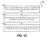
- FIG. 12 depicts a flowchart 1200 that can be performed by route programming component 508(X) of each affected switch 502(X) for carrying out this adjustment process according to an embodiment.
- Flowchart 1200 assumes that the owner sets of the system have already been modified for load balancing purposes.
- route programming component 508(X) can execute flowchart 700 of FIG. 7 (i.e., the initial programming flow) and mark, in SW routing table/trie 306(X), the routing entries to be installed in HW routing table 312(X).
- route programming component 508(X) can traverse the SW routing trie and remove the installed entries in HW routing table 312(X) that have not been marked per block 1202.
- route programming component 508(X) can traverse the SW routing trie once again and can install routing entries into HW routing table 312(X) that are marked in the SW routing trie but have not yet been installed.
- the order of blocks 1204 and 1206 can be reversed depending on different concerns. For example, removing installed entries (per block 1204) before adding new entries (per block 1206) may cause some incoming data traffic to not match any of the entries in the HW routing table. On the other hand, adding new entries before removing installed entries requires a sufficient amount of temporary space in the HW routing table, which may not be available.
- One way to address both of these concerns it to implement a hybrid approach that can calculate the amount of temporary space required and can determine whether to execute block 1206 before 1204 (or vice versa) based on that space requirement and the space actually available in the table.
Landscapes
- Engineering & Computer Science (AREA)
- Computer Networks & Wireless Communication (AREA)
- Signal Processing (AREA)
- Data Exchanges In Wide-Area Networks (AREA)
Claims (15)
- Un procédé comprenant le fait de :diviser, par un dispositif dans un système de dispositifs (500), des entrées de routage dans une table de routage logicielle du système en une pluralité de sous-ensembles de routes ;affecter, par le dispositif, chaque sous-ensemble de routes dans la pluralité de sous-ensembles de routes à un ou plusieurs dispositifs (502(1-N)) dans le système ;installer, par le dispositif pour chaque sous-ensemble de routes qui est affecté au dispositif, des entrées de routage dans le sous-ensemble de routes dans une table de routage matérielle (312) du dispositif (502) ; etinstaller au moins une entrée de redirection dans la table de routage matérielle (312) du dispositif (502), sachant que l'au moins une entrée de redirection correspond à une entrée de routage dans un sous-ensemble de routes qui n'est pas affecté au dispositif, et sachant que l'au moins une entrée de redirection identifie, en tant que bond suivant, un autre dispositif dans le système de dispositifs.
- Le procédé d'après la revendication 1, comprenant en outre le fait de savoir que le sous-ensemble de routes qui n'est pas affecté au dispositif est affecté audit autre dispositif.
- Le procédé d'après la revendication 1 ou 2 comprenant en outre le fait de :recevoir un paquet de données à un port d'entrée (ingress port) du dispositif ;déterminer une adresse IP de destination du paquet de données ;effectuer une recherche de l'adresse IP de destination dans la table de routage matérielle à l'aide d'un algorithme de correspondance du plus long préfixe (LPM) ; etsi l'algorithme LPM sélectionne une entrée de routage dans la table de routage matérielle comme correspondant à l'adresse IP de destination, transférer le paquet de données à un bond suivant identifié par l'entrée de routage correspondante.
- Le procédé d'après la revendication 3, sachant que le fait de transférer le paquet de données au bond suivant identifié par l'entrée de routage appariée comprend le fait de :décrémenter un champ TTL (time-to-live) du paquet de données ;remplacer une adresse MAC de destination du paquet de données par une adresse MAC du bond suivant ;remplacer une adresse MAC source du paquet de données par une adresse MAC associée au dispositif ou au système ; etenvoyer le paquet de données à partir d'un port de données de sortie (egress port) du dispositif.
- Le procédé d'après la revendication 3 ou 4 comprenant en outre :
si l'algorithme LPM sélectionne l'au moins une entrée de redirection comme appariée à l'adresse IP de destination, le fait de transférer le paquet de données audit autre dispositif. - Le procédé d'après la revendication 5, sachant que le fait de transférer le paquet de données audit autre dispositif comprend le fait d'envoyer le paquet de données d'un port de dispositif à dispositif audit autre dispositif, sans modifier le paquet de données ; et que
le procédé peut en outre comprendre, par ledit autre dispositif, le fait de :effectuer une deuxième recherche de l'adresse IP de destination dans une table de routage matérielle dudit autre dispositif ; et detransférer le paquet de données à un bond suivant sur la base de la deuxième recherche. - Le procédé d'après l'une quelconque des revendications de 1 à 6, sachant que la table de routage logicielle est maintenue en tant que arbre binaire (binary trie), et sachant que chaque entrée de routage dans la table de routage logicielle est représentée en tant que noeud de route dans l'arbre binaire; et
sachant que la division des entrées de routage de la table de routage logicielle en plusieurs sous-ensembles de routes peut comprendre le partitionnement des noeuds de route de l'arbre binaire. - Le procédé d'après la revendication 7, sachant que l'installation d'entrées de routage dans le sous-ensemble de routes dans la table de routage matérielle du dispositif comprend, pour chaque noeud de route dans l'arbre binaire :si le noeud de route fait partie d'un sous-ensemble de routes qui est affecté au dispositif, le fait d'installer l'entrée de routage correspondant au noeud de route dans la table de routage matérielle, etsachant que l'entrée de routage peut être non installée dans la table de routage matérielle si un bond suivant pour l'entrée de routage est identique à un bond suivant pour le parent du noeud de route dans l'arbre binaire.
- Le procédé d'après la revendication 7 ou 8, sachant que l'installation d'entrées de routage dans le sous-ensemble de routes dans la table de routage matérielle du dispositif comprend en outre, pour chaque noeud de route dans l'arbre binaire :
si le noeud de route ne fait pas partie d'un sous-ensemble de routes qui est affecté au dispositif, le fait de déterminer si le noeud de route et un parent du noeud de route dans l'arbre binaire font partie d'un ou plusieurs sous-ensembles de routes qui sont affectés à un dispositif commun. - Le procédé d'après la revendication 9, sachant que l'installation d'entrées de routage dans le sous-ensemble de routes dans la table de routage matérielle du dispositif comprend en outre, pour chaque noeud de route dans l'arbre binaire :
si le noeud de route et le parent ne font pas partie d'un ou plusieurs sous-ensembles de routes qui sont affectés à un dispositif commun, le fait d'installer une entrée de redirection dans la table de routage matérielle, l'entrée de redirection incluant une action pour transférer des paquets vers un dispositif dans le système de dispositifs auxquels le sous-ensemble de routes du noeud de route est affecté. - Le procédé d'après l'une quelconque des revendications de 1 à 10 comprenant en outre, si une entrée de routage est supprimée de la table de routage logicielle, le fait de :supprimer l'entrée de routage de la table de routage matérielle de chaque dispositif où elle est installée ; etajuster les entrées de routage enfant direct de l'entrée de routage supprimée dans la table de routage matérielle de chaque dispositif où elle est installée.
- Le procédé d'après l'une quelconque des revendications de 1 à 11, sachant que l'affectation de chaque sous-ensemble de routes dans la pluralité de sous-ensembles de routes à un ou plusieurs dispositifs dans le système comprend l'affectation de chaque sous-ensemble de routes à un sous-ensemble propriétaire, le sous-ensemble propriétaire incluant le ou les dispositifs.
- Le procédé d'après l'une quelconque des revendications de 1 à 12, sachant qu'au moins un sous-ensemble de routes est affecté à un sous-ensemble propriétaire incluant chaque dispositif dans le système de dispositifs, et que le procédé peut comprendre en outre le fait de :déterminer que la table de routage matérielle d'un dispositif dans le système de dispositifs est devenue pleine ou presque pleine ; et demodifier un ou plusieurs ensembles propriétaire pour changer les sous-ensembles de routes qui sont affectés au dispositif.
- Un support non transitoire lisible par ordinateur sur lequel est stocké un code de programme exécutable par un dispositif dans un système de dispositifs (500), le code de programme comprenant :un code qui amène le dispositif à diviser les entrées de routage dans une table de routage logicielle du système en une pluralité de sous-ensembles de routes;un code qui amène le dispositif à affecter chaque sous-ensemble de routes dans la pluralité de sous-ensembles de routes à un ou plusieurs dispositifs (502(1-N)) dans le système ;un code qui amène le dispositif à installer, pour chaque sous-ensemble de routes affecté au dispositif (502), des entrées de routage dans le sous-ensemble de routes dans une table de routage matérielle (312) du dispositif ; etun code qui amène le dispositif à installer au moins une entrée de redirection dans la table de routage matérielle (312) du dispositif (502), sachant que l'au moins une entrée de redirection correspond à une entrée de routage dans un sous-ensemble de routes qui n'est pas affecté au dispositif, et sachant que l'au moins une entrée de redirection identifie, comme bond suivant, un autre dispositif dans le système de dispositifs.
- Un dispositif destiné à être utilisé dans un système de dispositifs (500), le dispositif comprenant :une pluralité de ports de dispositif à dispositif (314) pour coupler de manière communicative le dispositif à un ou plusieurs autres dispositifs dans le système ;une pluralité de ports de données (316) ;une table de routage matérielle (312) ;un processeur (304) ; etun support non transitoire lisible par ordinateur sur lequel est stocké un code de programme exécutable qui, lorsqu'il est exécuté par le processeur, amène le processeur à :diviser des entrées de routage dans une table de routage logicielle du système en une pluralité de sous-ensembles de routes;affecter chaque sous-ensemble de routes de la pluralité de sous-ensembles de routes à un ou plusieurs dispositifs (502(1-N)) dans le système ;installer, pour chaque sous-ensemble de routes affecté au dispositif (502), des entrées de routage dans le sous-ensemble de routes dans la table de routage matérielle (312) ; et deinstaller au moins une entrée de redirection dans la table de routage matérielle (312) du dispositif (502), sachant que l'au moins une entrée de redirection correspond à une entrée de routage dans un sous-ensemble de routes qui n'est pas affecté au dispositif, et sachant que l'au moins une entrée de redirection identifie, en tant que bond suivant, un autre dispositif dans le système de dispositifs.
Applications Claiming Priority (2)
| Application Number | Priority Date | Filing Date | Title |
|---|---|---|---|
| US201461971429P | 2014-03-27 | 2014-03-27 | |
| US14/506,943 US9692695B2 (en) | 2014-03-27 | 2014-10-06 | Techniques for aggregating hardware routing resources in a multi-packet processor networking system |
Publications (2)
| Publication Number | Publication Date |
|---|---|
| EP2924927A1 EP2924927A1 (fr) | 2015-09-30 |
| EP2924927B1 true EP2924927B1 (fr) | 2018-09-19 |
Family
ID=52823427
Family Applications (1)
| Application Number | Title | Priority Date | Filing Date |
|---|---|---|---|
| EP15000834.0A Active EP2924927B1 (fr) | 2014-03-27 | 2015-03-20 | Techniques pour l'agrégation de ressources de routage matérielles dans un système de réseau à processeur multi-paquet |
Country Status (3)
| Country | Link |
|---|---|
| US (1) | US9692695B2 (fr) |
| EP (1) | EP2924927B1 (fr) |
| CN (1) | CN104954270B (fr) |
Families Citing this family (17)
| Publication number | Priority date | Publication date | Assignee | Title |
|---|---|---|---|---|
| US9559897B2 (en) | 2012-12-21 | 2017-01-31 | Brocade Communications Systems, Inc. | Device ID assignment in a system of devices |
| US9313102B2 (en) | 2013-05-20 | 2016-04-12 | Brocade Communications Systems, Inc. | Configuration validation in a mixed node topology |
| US9853889B2 (en) | 2013-05-20 | 2017-12-26 | Brocade Communications Systems, Inc. | Broadcast and multicast traffic reduction in stacking systems |
| CN104283811B (zh) * | 2013-07-09 | 2017-10-03 | 新华三技术有限公司 | 报文转发方法和装置 |
| US10284499B2 (en) | 2013-08-22 | 2019-05-07 | Arris Enterprises Llc | Dedicated control path architecture for systems of devices |
| US9185049B2 (en) | 2013-10-31 | 2015-11-10 | Brocade Communications Systems, Inc. | Techniques for simplifying stacking trunk creation and management |
| US9577932B2 (en) | 2014-02-12 | 2017-02-21 | Brocade Communications Systems, Inc. | Techniques for managing ternary content-addressable memory (TCAM) resources in heterogeneous systems |
| US9692652B2 (en) | 2014-04-03 | 2017-06-27 | Brocade Communications Systems, Inc. | Framework for reliably communicating port information in a system of devices |
| US9866472B2 (en) | 2014-12-09 | 2018-01-09 | Oath Inc. | Systems and methods for software defined networking service function chaining |
| US10091059B2 (en) | 2014-12-16 | 2018-10-02 | Arris Enterprises Llc | Handling connections between network devices that support multiple port communication modes |
| WO2018046986A1 (fr) * | 2016-09-09 | 2018-03-15 | Telefonaktiebolaget Lm Ericsson (Publ) | Techniques de reconstruction de base d'informations de réacheminement efficace à l'aide d'identifiants de points de récolte |
| JP6683090B2 (ja) * | 2016-09-26 | 2020-04-15 | 株式会社デンソー | 中継装置 |
| US10382333B2 (en) * | 2017-05-31 | 2019-08-13 | Juniper Networks, Inc. | Fabric path context-based forwarding for virtual nodes |
| US10764241B2 (en) | 2018-03-01 | 2020-09-01 | Dell Products L.P. | Address assignment and data forwarding in computer networks |
| CN108919762B (zh) * | 2018-07-06 | 2021-05-25 | 东莞市李群自动化技术有限公司 | 基于工业以太网的控制方法及装置 |
| CN111049746B (zh) | 2018-10-12 | 2022-04-22 | 华为技术有限公司 | 一种路由表项生成方法、字典树生成方法和装置 |
| CN114124704B (zh) * | 2021-11-19 | 2024-01-23 | 北京天融信网络安全技术有限公司 | 路由优化方法、装置、电子设备及存储介质 |
Family Cites Families (120)
| Publication number | Priority date | Publication date | Assignee | Title |
|---|---|---|---|---|
| US4625308A (en) | 1982-11-30 | 1986-11-25 | American Satellite Company | All digital IDMA dynamic channel allocated satellite communications system and method |
| US5481073A (en) | 1994-06-09 | 1996-01-02 | Quintech, Inc. | Modular broadband bidirectional programmable switch system with stacked modular switch arrangement |
| US5651003A (en) | 1995-06-07 | 1997-07-22 | Whitetree, Inc. | Stackable data cell switch architecture |
| US6243756B1 (en) | 1997-06-23 | 2001-06-05 | Compaq Computer Corporation | Network device with unified management |
| DE69837872T2 (de) | 1997-09-19 | 2008-04-10 | Hitachi, Ltd. | Vorrichtung und Verfahren zur Verbindungsvermittlung und -steuerung |
| TW454124B (en) | 1997-11-28 | 2001-09-11 | Accton Technology Corp | Network stack with automatic switch device for the switch |
| US6111672A (en) | 1998-02-20 | 2000-08-29 | Mci Communications Corporation | Method, apparatus, and computer program product for optical network restoration |
| US6496502B1 (en) | 1998-06-29 | 2002-12-17 | Nortel Networks Limited | Distributed multi-link trunking method and apparatus |
| US6490276B1 (en) | 1998-06-29 | 2002-12-03 | Nortel Networks Limited | Stackable switch port collapse mechanism |
| US6654761B2 (en) | 1998-07-29 | 2003-11-25 | Inxight Software, Inc. | Controlling which part of data defining a node-link structure is in memory |
| US6597658B1 (en) | 1998-12-28 | 2003-07-22 | At&T Corp. | Hierarchical telecommunications network with fault recovery |
| ATE343886T1 (de) | 1999-03-17 | 2006-11-15 | Broadcom Corp | Netzwerkvermittlung |
| US6377987B1 (en) | 1999-04-30 | 2002-04-23 | Cisco Technology, Inc. | Mechanism for determining actual physical topology of network based on gathered configuration information representing true neighboring devices |
| US6765877B1 (en) | 1999-08-30 | 2004-07-20 | Cisco Technology, Inc. | System and method for detecting unidirectional links |
| GB2356110B (en) | 1999-11-02 | 2001-10-03 | 3Com Corp | Stacked network devices including a protocol engine and distributed trunk ports and method of operating same |
| AU2066201A (en) | 1999-12-07 | 2001-06-18 | Broadcom Corporation | Mirroring in a stacked network switch configuration |
| US7426179B1 (en) | 2000-03-17 | 2008-09-16 | Lucent Technologies Inc. | Method and apparatus for signaling path restoration information in a mesh network |
| US7120683B2 (en) | 2000-04-03 | 2006-10-10 | Zarlink Semiconductor V.N. Inc. | Single switch image for a stack of switches |
| EP1162792B1 (fr) | 2000-06-09 | 2012-08-15 | Broadcom Corporation | Gigabit-conmutateur avec renvoi rapide de trames et apprentissage d'adresses |
| US6725326B1 (en) | 2000-08-15 | 2004-04-20 | Cisco Technology, Inc. | Techniques for efficient memory management for longest prefix match problems |
| EP1193917B1 (fr) | 2000-09-20 | 2006-01-04 | Broadcom Corporation | Commutateur de réseau ayant la possibilité de bloquer un port |
| US6839342B1 (en) | 2000-10-09 | 2005-01-04 | General Bandwidth Inc. | System and method for interfacing signaling information and voice traffic |
| US6850542B2 (en) | 2000-11-14 | 2005-02-01 | Broadcom Corporation | Linked network switch configuration |
| KR20020058782A (ko) | 2000-12-30 | 2002-07-12 | 이계안 | 차량 속도 제어방법 및 시스템 |
| GB2371705B (en) | 2001-01-30 | 2003-04-23 | 3Com Corp | Network switch with mutually coupled look-up engine and network processor |
| US7206309B2 (en) | 2001-03-27 | 2007-04-17 | Nortel Networks Limited | High availability packet forward apparatus and method |
| US7035937B2 (en) | 2001-04-25 | 2006-04-25 | Cornell Research Foundation, Inc. | Independent-tree ad hoc multicast routing |
| US7206283B2 (en) | 2001-05-15 | 2007-04-17 | Foundry Networks, Inc. | High-performance network switch |
| US7002965B1 (en) | 2001-05-21 | 2006-02-21 | Cisco Technology, Inc. | Method and apparatus for using ternary and binary content-addressable memory stages to classify packets |
| US7139267B2 (en) | 2002-03-05 | 2006-11-21 | Industrial Technology Research Institute | System and method of stacking network switches |
| US8112578B2 (en) | 2001-11-01 | 2012-02-07 | Micron Technology, Inc. | Low power, hash-content addressable memory architecture |
| US7496096B1 (en) | 2002-01-31 | 2009-02-24 | Cisco Technology, Inc. | Method and system for defining hardware routing paths for networks having IP and MPLS paths |
| JP2003258842A (ja) * | 2002-02-28 | 2003-09-12 | Ntt Docomo Inc | パケット通信システム及び転送装置 |
| US7161948B2 (en) | 2002-03-15 | 2007-01-09 | Broadcom Corporation | High speed protocol for interconnecting modular network devices |
| US7007123B2 (en) | 2002-03-28 | 2006-02-28 | Alcatel | Binary tree arbitration system and method using embedded logic structure for controlling flag direction in multi-level arbiter node |
| US7327727B2 (en) | 2002-06-04 | 2008-02-05 | Lucent Technologies Inc. | Atomic lookup rule set transition |
| US7093027B1 (en) | 2002-07-23 | 2006-08-15 | Atrica Israel Ltd. | Fast connection protection in a virtual local area network based stack environment |
| US7313667B1 (en) | 2002-08-05 | 2007-12-25 | Cisco Technology, Inc. | Methods and apparatus for mapping fields of entries into new values and combining these mapped values into mapped entries for use in lookup operations such as for packet processing |
| US7697419B1 (en) | 2002-11-22 | 2010-04-13 | Allied Telesyn International Corporation | Apparatus and method for managing a set of switches in a computer network |
| US7274694B1 (en) | 2003-01-09 | 2007-09-25 | Cisco Technology, Inc. | Defining link aggregation across a stack |
| US7523227B1 (en) | 2003-01-14 | 2009-04-21 | Cisco Technology, Inc. | Interchangeable standard port or stack port |
| US7480258B1 (en) | 2003-07-03 | 2009-01-20 | Cisco Technology, Inc. | Cross stack rapid transition protocol |
| US7415011B2 (en) | 2003-08-29 | 2008-08-19 | Sun Microsystems, Inc. | Distributed switch |
| US7336622B1 (en) | 2003-09-08 | 2008-02-26 | Cisco Technology, Inc. | Method and system for resolving switch number conflicts in a stackable switch system |
| US7234019B1 (en) | 2003-12-12 | 2007-06-19 | Raza Microelectronics, Inc. | Method and apparatus for implementing a search engine using an SRAM |
| KR100564768B1 (ko) | 2003-12-26 | 2006-03-27 | 한국전자통신연구원 | 순차룩업에 의한 패킷헤더 룩업장치 및 방법 |
| US7111139B2 (en) | 2004-03-02 | 2006-09-19 | Hitachi, Ltd. | Data synchronization of multiple remote storage |
| CN100370740C (zh) | 2004-03-06 | 2008-02-20 | 鸿富锦精密工业(深圳)有限公司 | 堆叠式交换机管理方法 |
| CN1954560B (zh) | 2004-03-31 | 2011-06-15 | Ipt株式会社 | 固定长数据的检索装置及检索管理方法 |
| WO2005112346A2 (fr) | 2004-04-29 | 2005-11-24 | Dematic Corp. | Decouverte de topologie de reseau |
| US7290083B2 (en) | 2004-06-29 | 2007-10-30 | Cisco Technology, Inc. | Error protection for lookup operations in content-addressable memory entries |
| US20060013212A1 (en) | 2004-07-13 | 2006-01-19 | Hartej Singh | Port aggregation across stack of devices |
| US7974272B2 (en) | 2004-07-29 | 2011-07-05 | Conexant Systems, Inc. | Remote control of a switching node in a stack of switching nodes |
| US7136289B2 (en) | 2004-08-30 | 2006-11-14 | Cisco Technology, Inc. | Dual-stacked 10 Gigabit X2 uplinks in a single rack unit switch |
| US7489683B2 (en) | 2004-09-29 | 2009-02-10 | Intel Corporation | Integrated circuit capable of routing multicast data packets using device vectors |
| US7522541B2 (en) | 2004-10-11 | 2009-04-21 | International Business Machines Corporation | Identification of the configuration topology, existing switches, and miswires in a switched network |
| US7483383B2 (en) | 2004-10-28 | 2009-01-27 | Alcatel Lucent | Stack manager protocol with automatic set up mechanism |
| US7505403B2 (en) | 2004-10-28 | 2009-03-17 | Alcatel Lucent | Stack manager protocol with automatic set up mechanism |
| JP4369351B2 (ja) * | 2004-11-30 | 2009-11-18 | 株式会社日立製作所 | パケット転送装置 |
| KR100612256B1 (ko) | 2005-01-14 | 2006-08-14 | 삼성전자주식회사 | 터너리 내용 주소화 메모리 관리 장치 및 그 방법 |
| US7852831B2 (en) | 2005-02-22 | 2010-12-14 | Akbar Imran M | Method and system for providing private virtual secure Voice over Internet Protocol communications |
| EP1854250B1 (fr) | 2005-02-28 | 2011-09-21 | International Business Machines Corporation | Systeme de serveurs a baie de commutation possedant plusieurs commutateurs interconnectes et configures pour la gestion et la mise en oeuvre comme commutateur virtuel unique |
| US7570601B2 (en) | 2005-04-06 | 2009-08-04 | Broadcom Corporation | High speed autotrunking |
| US8135806B2 (en) | 2005-05-06 | 2012-03-13 | Broadcom Corporation | Virtual system configuration |
| US7978719B2 (en) | 2005-06-10 | 2011-07-12 | International Business Machines Corporation | Dynamically assigning endpoint identifiers to network interfaces of communications networks |
| WO2007002466A2 (fr) | 2005-06-22 | 2007-01-04 | Netlogic Microsystems, Inc. | Processeur de listes de contrôle d'accès |
| US20070081463A1 (en) | 2005-10-11 | 2007-04-12 | Subash Bohra | System and Method for Negotiating Stack Link Speed in a Stackable Ethernet Switch System |
| US8045473B2 (en) | 2005-11-28 | 2011-10-25 | Cisco Technology, Inc. | Tailored relief for congestion on application servers for real time communications |
| EP1977635A2 (fr) | 2006-01-13 | 2008-10-08 | Sun Microsystems, Inc. | Serveur lame modulaire |
| US7904642B1 (en) | 2007-02-08 | 2011-03-08 | Netlogic Microsystems, Inc. | Method for combining and storing access control lists |
| KR100864888B1 (ko) | 2007-02-12 | 2008-10-22 | 삼성전자주식회사 | 라우팅 시스템 및 라우팅 시스템의 룰 엔트리 관리 방법 |
| US7978700B2 (en) | 2007-03-12 | 2011-07-12 | Marvell Israel (Misl) Ltd. | Apparatus for determining locations of fields in a data unit |
| US7814192B2 (en) | 2007-05-09 | 2010-10-12 | Computer Associates Think, Inc. | System and method for automatically deploying a network design |
| US7793032B2 (en) | 2007-07-11 | 2010-09-07 | Commex Technologies, Ltd. | Systems and methods for efficient handling of data traffic and processing within a processing device |
| US8667095B2 (en) | 2007-11-09 | 2014-03-04 | Cisco Technology, Inc. | Local auto-configuration of network devices connected to multipoint virtual connections |
| US8213297B2 (en) | 2007-11-27 | 2012-07-03 | International Business Machines Corporation | Duplicate internet protocol address resolution in a fragmented switch stack environment |
| JP5086780B2 (ja) | 2007-11-29 | 2012-11-28 | アラクサラネットワークス株式会社 | 通信装置および通信システム、並びに通信障害検出方法 |
| CN101478434B (zh) | 2009-01-19 | 2011-07-06 | 杭州华三通信技术有限公司 | 一种配置堆叠端口的方法和交换设备 |
| CN101478435B (zh) | 2009-01-20 | 2011-01-12 | 杭州华三通信技术有限公司 | 一种堆叠系统的拓扑收集方法和双控制板设备 |
| US9032057B2 (en) | 2009-04-06 | 2015-05-12 | Brocade Communications Systems, Inc. | Secure stacking setup implementing user interface of stacking device |
| US9282057B2 (en) | 2009-05-11 | 2016-03-08 | Brocade Communication Systems, Inc. | Flexible stacking port |
| US8619605B2 (en) | 2009-05-13 | 2013-12-31 | Avaya Inc. | Method and apparatus for maintaining port state tables in a forwarding plane of a network element |
| CN101610182B (zh) | 2009-06-26 | 2011-09-07 | 杭州华三通信技术有限公司 | 堆叠中多主用设备冲突检测方法及堆叠成员设备 |
| US8654680B2 (en) | 2010-03-16 | 2014-02-18 | Force10 Networks, Inc. | Packet forwarding using multiple stacked chassis |
| US8645631B2 (en) | 2010-03-29 | 2014-02-04 | Via Technologies, Inc. | Combined L2 cache and L1D cache prefetcher |
| US8307153B2 (en) | 2010-05-05 | 2012-11-06 | Juniper Networks, Inc. | Power efficient and rule movement optimized TCAM management |
| CA2810486A1 (fr) | 2010-09-08 | 2012-03-15 | Nec Corporation | Systeme de commutation, procede de commande de commutation et support de memoire |
| US20120087232A1 (en) | 2010-10-12 | 2012-04-12 | Brocade Communications Systems, Inc. | Link state relay for physical layer emulation |
| US8750144B1 (en) | 2010-10-20 | 2014-06-10 | Google Inc. | System and method for reducing required memory updates |
| US20120155485A1 (en) | 2010-12-16 | 2012-06-21 | Fujitsu Network Communications, Inc. | Efficient space utilization of distributed mac address tables in ethernet switches |
| US10097456B2 (en) | 2011-02-25 | 2018-10-09 | Nokia Technologies Oy | Method and an apparatus for a gateway |
| US8874876B2 (en) | 2011-03-22 | 2014-10-28 | Texas Instruments Incorporated | Method and apparatus for packet switching |
| US8891527B2 (en) | 2012-02-03 | 2014-11-18 | Gigamon Inc. | Systems and methods for packet filtering and switching |
| US20130232193A1 (en) | 2012-03-04 | 2013-09-05 | Zafar Ali | Control-Plane Interface Between Layers in a Multilayer Network |
| CN102684999B (zh) * | 2012-04-20 | 2015-05-20 | 中兴通讯股份有限公司 | 数据包处理方法及装置 |
| US9098601B2 (en) | 2012-06-27 | 2015-08-04 | Futurewei Technologies, Inc. | Ternary content-addressable memory assisted packet classification |
| US8923113B2 (en) | 2012-06-27 | 2014-12-30 | Cisco Technology, Inc. | Optimizations in multi-destination tree calculations for layer 2 link state protocols |
| US9269439B1 (en) | 2012-08-31 | 2016-02-23 | Marvell Israel (M.I.S.L) Ltd. | Method and apparatus for TCAM based look-up |
| US10097378B2 (en) | 2012-09-07 | 2018-10-09 | Cisco Technology, Inc. | Efficient TCAM resource sharing |
| US8937945B2 (en) | 2012-09-12 | 2015-01-20 | Alcatel Lucent | Method and apparatus for optimizing usage of ternary content addressable memory (TCAM) |
| US9038151B1 (en) | 2012-09-20 | 2015-05-19 | Wiretap Ventures, LLC | Authentication for software defined networks |
| US9106515B2 (en) | 2012-10-22 | 2015-08-11 | Futurewei Technologies, Inc. | System and apparatus of a software-service-defined-network (SSDN) |
| US8982727B2 (en) | 2012-10-22 | 2015-03-17 | Futurewei Technologies, Inc. | System and apparatus of generalized network controller for a software defined network (SDN) |
| US9245626B2 (en) | 2012-10-26 | 2016-01-26 | Cisco Technology, Inc. | System and method for packet classification and internet protocol lookup in a network environment |
| US9154370B2 (en) | 2012-11-05 | 2015-10-06 | Cisco Technology, Inc. | Seamless multipath retransmission using source-routed tunnels |
| US8937955B2 (en) * | 2012-12-05 | 2015-01-20 | Cisco Technology, Inc. | System and method for scaling IPv6 addresses in a network environment |
| US9559897B2 (en) | 2012-12-21 | 2017-01-31 | Brocade Communications Systems, Inc. | Device ID assignment in a system of devices |
| US9426020B2 (en) | 2013-03-15 | 2016-08-23 | Cisco Technology, Inc. | Dynamically enabling selective routing capability |
| US9148387B2 (en) | 2013-05-10 | 2015-09-29 | Brocade Communications Systems, Inc. | Hardware hash table virtualization in multi-packet processor networking systems |
| US9853889B2 (en) | 2013-05-20 | 2017-12-26 | Brocade Communications Systems, Inc. | Broadcast and multicast traffic reduction in stacking systems |
| US9313102B2 (en) | 2013-05-20 | 2016-04-12 | Brocade Communications Systems, Inc. | Configuration validation in a mixed node topology |
| US9225589B2 (en) | 2013-06-19 | 2015-12-29 | Cisco Technology, Inc. | Fast reroute using different frequency-hopping schedules |
| US20150016277A1 (en) | 2013-07-10 | 2015-01-15 | Dell Products L.P. | Interconnect error notification system |
| US9503322B2 (en) | 2013-07-31 | 2016-11-22 | Dell Products L.P. | Automatic stack unit replacement system |
| US10284499B2 (en) | 2013-08-22 | 2019-05-07 | Arris Enterprises Llc | Dedicated control path architecture for systems of devices |
| US9185049B2 (en) | 2013-10-31 | 2015-11-10 | Brocade Communications Systems, Inc. | Techniques for simplifying stacking trunk creation and management |
| EP3605971B1 (fr) * | 2013-11-05 | 2021-10-13 | Cisco Technology, Inc. | Superposition de tissu unifié |
| US9577932B2 (en) | 2014-02-12 | 2017-02-21 | Brocade Communications Systems, Inc. | Techniques for managing ternary content-addressable memory (TCAM) resources in heterogeneous systems |
| US9692652B2 (en) | 2014-04-03 | 2017-06-27 | Brocade Communications Systems, Inc. | Framework for reliably communicating port information in a system of devices |
| US10091059B2 (en) | 2014-12-16 | 2018-10-02 | Arris Enterprises Llc | Handling connections between network devices that support multiple port communication modes |
-
2014
- 2014-10-06 US US14/506,943 patent/US9692695B2/en active Active
-
2015
- 2015-03-20 EP EP15000834.0A patent/EP2924927B1/fr active Active
- 2015-03-27 CN CN201510142392.XA patent/CN104954270B/zh active Active
Non-Patent Citations (1)
| Title |
|---|
| None * |
Also Published As
| Publication number | Publication date |
|---|---|
| CN104954270A (zh) | 2015-09-30 |
| EP2924927A1 (fr) | 2015-09-30 |
| US20150281055A1 (en) | 2015-10-01 |
| CN104954270B (zh) | 2018-08-28 |
| US9692695B2 (en) | 2017-06-27 |
Similar Documents
| Publication | Publication Date | Title |
|---|---|---|
| EP2924927B1 (fr) | Techniques pour l'agrégation de ressources de routage matérielles dans un système de réseau à processeur multi-paquet | |
| US8432914B2 (en) | Method for optimizing a network prefix-list search | |
| US9246810B2 (en) | Hash-based load balancing with per-hop seeding | |
| US8937955B2 (en) | System and method for scaling IPv6 addresses in a network environment | |
| US10284472B2 (en) | Dynamic and compressed trie for use in route lookup | |
| US8014278B1 (en) | Adaptive load balancing between ECMP or LAG port group members | |
| US8307153B2 (en) | Power efficient and rule movement optimized TCAM management | |
| KR102397876B1 (ko) | 고성능 컴퓨팅(hpc) 환경에서 효율적인 로드-발란싱을 지원하기 위한 시스템 및 방법 | |
| US9973435B2 (en) | Loopback-free adaptive routing | |
| US20180026878A1 (en) | Scalable deadlock-free deterministic minimal-path routing for dragonfly networks | |
| CN107710700B (zh) | 处理计算机网络中的分组的系统和方法 | |
| US8804735B2 (en) | Scalable forwarding table with overflow address learning | |
| Schwabe et al. | Using MAC addresses as efficient routing labels in data centers | |
| EP2995048A1 (fr) | Configuration d'informations d'acheminement | |
| CN108400922B (zh) | 虚拟局域网络配置系统与方法及其计算机可读存储介质 | |
| EP3292660B1 (fr) | Transfert de paquets dans un commutateur vxlan | |
| WO2015116291A1 (fr) | Hachage cohérent utilisant la mise en correspondance exacte dôté d'une application à l'équilibrage de charge de matériel | |
| US11431626B2 (en) | Forwarding rules among lookup tables in a multi-stage packet processor | |
| US11962485B2 (en) | Selecting and deduplicating forwarding equivalence classes | |
| Dürr | A flat and scalable data center network topology based on De Bruijn graphs | |
| US8407779B1 (en) | Transposing a packet firewall policy within a node | |
| US20220239595A1 (en) | Increasing multi-path size using hierarchical forwarding equivalent classes | |
| Anand et al. | An efficient mask reduction strategy to optimize storage and computational complexity in routing table lookups | |
| Kuo et al. | AN EFFICIENT AND LOW OVERHEAD RANDOM FORWARDING TABLE CONSTRUCTION METHOD FOR DEADLOCK-FREE ROUTING | |
| GB2518020A (en) | Method and apparatus providing single-tier routing in a shortest path bridging (SPB) network |
Legal Events
| Date | Code | Title | Description |
|---|---|---|---|
| PUAI | Public reference made under article 153(3) epc to a published international application that has entered the european phase |
Free format text: ORIGINAL CODE: 0009012 |
|
| AK | Designated contracting states |
Kind code of ref document: A1 Designated state(s): AL AT BE BG CH CY CZ DE DK EE ES FI FR GB GR HR HU IE IS IT LI LT LU LV MC MK MT NL NO PL PT RO RS SE SI SK SM TR |
|
| AX | Request for extension of the european patent |
Extension state: BA ME |
|
| 17P | Request for examination filed |
Effective date: 20160330 |
|
| RBV | Designated contracting states (corrected) |
Designated state(s): AL AT BE BG CH CY CZ DE DK EE ES FI FR GB GR HR HU IE IS IT LI LT LU LV MC MK MT NL NO PL PT RO RS SE SI SK SM TR |
|
| GRAP | Despatch of communication of intention to grant a patent |
Free format text: ORIGINAL CODE: EPIDOSNIGR1 |
|
| STAA | Information on the status of an ep patent application or granted ep patent |
Free format text: STATUS: GRANT OF PATENT IS INTENDED |
|
| RAP1 | Party data changed (applicant data changed or rights of an application transferred) |
Owner name: ARRIS INTERNATIONAL IP LTD. |
|
| RIC1 | Information provided on ipc code assigned before grant |
Ipc: H04L 12/741 20130101ALI20180410BHEP Ipc: H04L 12/701 20130101AFI20180410BHEP Ipc: H04L 12/933 20130101ALI20180410BHEP |
|
| INTG | Intention to grant announced |
Effective date: 20180430 |
|
| GRAS | Grant fee paid |
Free format text: ORIGINAL CODE: EPIDOSNIGR3 |
|
| GRAA | (expected) grant |
Free format text: ORIGINAL CODE: 0009210 |
|
| STAA | Information on the status of an ep patent application or granted ep patent |
Free format text: STATUS: THE PATENT HAS BEEN GRANTED |
|
| RIN1 | Information on inventor provided before grant (corrected) |
Inventor name: LIN, KWUN-NAN KEVIN Inventor name: DINDORKAR, SIDDHESH Inventor name: SINHA, VISHAL Inventor name: GUAN, TAO Inventor name: ZHANG, GEFAN Inventor name: BAFNA, KALPESH |
|
| AK | Designated contracting states |
Kind code of ref document: B1 Designated state(s): AL AT BE BG CH CY CZ DE DK EE ES FI FR GB GR HR HU IE IS IT LI LT LU LV MC MK MT NL NO PL PT RO RS SE SI SK SM TR |
|
| REG | Reference to a national code |
Ref country code: GB Ref legal event code: FG4D |
|
| RIN2 | Information on inventor provided after grant (corrected) |
Inventor name: BAFNA, KALPESH Inventor name: LIN, KWUN-NAN KEVIN Inventor name: DINDORKAR, SIDDHESH Inventor name: ZHANG, GEFAN Inventor name: SINHA, VISHAL Inventor name: GUAN, TAO |
|
| REG | Reference to a national code |
Ref country code: CH Ref legal event code: EP |
|
| REG | Reference to a national code |
Ref country code: AT Ref legal event code: REF Ref document number: 1044550 Country of ref document: AT Kind code of ref document: T Effective date: 20181015 |
|
| REG | Reference to a national code |
Ref country code: IE Ref legal event code: FG4D |
|
| REG | Reference to a national code |
Ref country code: DE Ref legal event code: R096 Ref document number: 602015016399 Country of ref document: DE |
|
| REG | Reference to a national code |
Ref country code: CH Ref legal event code: NV Representative=s name: PATENTANWAELTE SCHAAD, BALASS, MENZL AND PARTN, CH |
|
| REG | Reference to a national code |
Ref country code: NL Ref legal event code: FP |
|
| PG25 | Lapsed in a contracting state [announced via postgrant information from national office to epo] |
Ref country code: NO Free format text: LAPSE BECAUSE OF FAILURE TO SUBMIT A TRANSLATION OF THE DESCRIPTION OR TO PAY THE FEE WITHIN THE PRESCRIBED TIME-LIMIT Effective date: 20181219 Ref country code: SE Free format text: LAPSE BECAUSE OF FAILURE TO SUBMIT A TRANSLATION OF THE DESCRIPTION OR TO PAY THE FEE WITHIN THE PRESCRIBED TIME-LIMIT Effective date: 20180919 Ref country code: BG Free format text: LAPSE BECAUSE OF FAILURE TO SUBMIT A TRANSLATION OF THE DESCRIPTION OR TO PAY THE FEE WITHIN THE PRESCRIBED TIME-LIMIT Effective date: 20181219 Ref country code: LT Free format text: LAPSE BECAUSE OF FAILURE TO SUBMIT A TRANSLATION OF THE DESCRIPTION OR TO PAY THE FEE WITHIN THE PRESCRIBED TIME-LIMIT Effective date: 20180919 Ref country code: FI Free format text: LAPSE BECAUSE OF FAILURE TO SUBMIT A TRANSLATION OF THE DESCRIPTION OR TO PAY THE FEE WITHIN THE PRESCRIBED TIME-LIMIT Effective date: 20180919 Ref country code: GR Free format text: LAPSE BECAUSE OF FAILURE TO SUBMIT A TRANSLATION OF THE DESCRIPTION OR TO PAY THE FEE WITHIN THE PRESCRIBED TIME-LIMIT Effective date: 20181220 Ref country code: RS Free format text: LAPSE BECAUSE OF FAILURE TO SUBMIT A TRANSLATION OF THE DESCRIPTION OR TO PAY THE FEE WITHIN THE PRESCRIBED TIME-LIMIT Effective date: 20180919 |
|
| REG | Reference to a national code |
Ref country code: LT Ref legal event code: MG4D |
|
| PG25 | Lapsed in a contracting state [announced via postgrant information from national office to epo] |
Ref country code: HR Free format text: LAPSE BECAUSE OF FAILURE TO SUBMIT A TRANSLATION OF THE DESCRIPTION OR TO PAY THE FEE WITHIN THE PRESCRIBED TIME-LIMIT Effective date: 20180919 Ref country code: LV Free format text: LAPSE BECAUSE OF FAILURE TO SUBMIT A TRANSLATION OF THE DESCRIPTION OR TO PAY THE FEE WITHIN THE PRESCRIBED TIME-LIMIT Effective date: 20180919 Ref country code: AL Free format text: LAPSE BECAUSE OF FAILURE TO SUBMIT A TRANSLATION OF THE DESCRIPTION OR TO PAY THE FEE WITHIN THE PRESCRIBED TIME-LIMIT Effective date: 20180919 |
|
| REG | Reference to a national code |
Ref country code: AT Ref legal event code: MK05 Ref document number: 1044550 Country of ref document: AT Kind code of ref document: T Effective date: 20180919 |
|
| PG25 | Lapsed in a contracting state [announced via postgrant information from national office to epo] |
Ref country code: EE Free format text: LAPSE BECAUSE OF FAILURE TO SUBMIT A TRANSLATION OF THE DESCRIPTION OR TO PAY THE FEE WITHIN THE PRESCRIBED TIME-LIMIT Effective date: 20180919 Ref country code: IT Free format text: LAPSE BECAUSE OF FAILURE TO SUBMIT A TRANSLATION OF THE DESCRIPTION OR TO PAY THE FEE WITHIN THE PRESCRIBED TIME-LIMIT Effective date: 20180919 Ref country code: AT Free format text: LAPSE BECAUSE OF FAILURE TO SUBMIT A TRANSLATION OF THE DESCRIPTION OR TO PAY THE FEE WITHIN THE PRESCRIBED TIME-LIMIT Effective date: 20180919 Ref country code: CZ Free format text: LAPSE BECAUSE OF FAILURE TO SUBMIT A TRANSLATION OF THE DESCRIPTION OR TO PAY THE FEE WITHIN THE PRESCRIBED TIME-LIMIT Effective date: 20180919 Ref country code: RO Free format text: LAPSE BECAUSE OF FAILURE TO SUBMIT A TRANSLATION OF THE DESCRIPTION OR TO PAY THE FEE WITHIN THE PRESCRIBED TIME-LIMIT Effective date: 20180919 Ref country code: IS Free format text: LAPSE BECAUSE OF FAILURE TO SUBMIT A TRANSLATION OF THE DESCRIPTION OR TO PAY THE FEE WITHIN THE PRESCRIBED TIME-LIMIT Effective date: 20190119 Ref country code: ES Free format text: LAPSE BECAUSE OF FAILURE TO SUBMIT A TRANSLATION OF THE DESCRIPTION OR TO PAY THE FEE WITHIN THE PRESCRIBED TIME-LIMIT Effective date: 20180919 Ref country code: PL Free format text: LAPSE BECAUSE OF FAILURE TO SUBMIT A TRANSLATION OF THE DESCRIPTION OR TO PAY THE FEE WITHIN THE PRESCRIBED TIME-LIMIT Effective date: 20180919 |
|
| PG25 | Lapsed in a contracting state [announced via postgrant information from national office to epo] |
Ref country code: SK Free format text: LAPSE BECAUSE OF FAILURE TO SUBMIT A TRANSLATION OF THE DESCRIPTION OR TO PAY THE FEE WITHIN THE PRESCRIBED TIME-LIMIT Effective date: 20180919 Ref country code: PT Free format text: LAPSE BECAUSE OF FAILURE TO SUBMIT A TRANSLATION OF THE DESCRIPTION OR TO PAY THE FEE WITHIN THE PRESCRIBED TIME-LIMIT Effective date: 20190119 Ref country code: SM Free format text: LAPSE BECAUSE OF FAILURE TO SUBMIT A TRANSLATION OF THE DESCRIPTION OR TO PAY THE FEE WITHIN THE PRESCRIBED TIME-LIMIT Effective date: 20180919 |
|
| REG | Reference to a national code |
Ref country code: DE Ref legal event code: R097 Ref document number: 602015016399 Country of ref document: DE |
|
| PLBE | No opposition filed within time limit |
Free format text: ORIGINAL CODE: 0009261 |
|
| STAA | Information on the status of an ep patent application or granted ep patent |
Free format text: STATUS: NO OPPOSITION FILED WITHIN TIME LIMIT |
|
| PG25 | Lapsed in a contracting state [announced via postgrant information from national office to epo] |
Ref country code: DK Free format text: LAPSE BECAUSE OF FAILURE TO SUBMIT A TRANSLATION OF THE DESCRIPTION OR TO PAY THE FEE WITHIN THE PRESCRIBED TIME-LIMIT Effective date: 20180919 |
|
| 26N | No opposition filed |
Effective date: 20190620 |
|
| PG25 | Lapsed in a contracting state [announced via postgrant information from national office to epo] |
Ref country code: MC Free format text: LAPSE BECAUSE OF FAILURE TO SUBMIT A TRANSLATION OF THE DESCRIPTION OR TO PAY THE FEE WITHIN THE PRESCRIBED TIME-LIMIT Effective date: 20180919 Ref country code: SI Free format text: LAPSE BECAUSE OF FAILURE TO SUBMIT A TRANSLATION OF THE DESCRIPTION OR TO PAY THE FEE WITHIN THE PRESCRIBED TIME-LIMIT Effective date: 20180919 |
|
| PG25 | Lapsed in a contracting state [announced via postgrant information from national office to epo] |
Ref country code: LU Free format text: LAPSE BECAUSE OF NON-PAYMENT OF DUE FEES Effective date: 20190320 |
|
| PG25 | Lapsed in a contracting state [announced via postgrant information from national office to epo] |
Ref country code: IE Free format text: LAPSE BECAUSE OF NON-PAYMENT OF DUE FEES Effective date: 20190320 |
|
| PG25 | Lapsed in a contracting state [announced via postgrant information from national office to epo] |
Ref country code: FR Free format text: LAPSE BECAUSE OF NON-PAYMENT OF DUE FEES Effective date: 20190331 |
|
| PG25 | Lapsed in a contracting state [announced via postgrant information from national office to epo] |
Ref country code: TR Free format text: LAPSE BECAUSE OF FAILURE TO SUBMIT A TRANSLATION OF THE DESCRIPTION OR TO PAY THE FEE WITHIN THE PRESCRIBED TIME-LIMIT Effective date: 20180919 |
|
| PG25 | Lapsed in a contracting state [announced via postgrant information from national office to epo] |
Ref country code: MT Free format text: LAPSE BECAUSE OF NON-PAYMENT OF DUE FEES Effective date: 20190320 |
|
| PG25 | Lapsed in a contracting state [announced via postgrant information from national office to epo] |
Ref country code: CY Free format text: LAPSE BECAUSE OF FAILURE TO SUBMIT A TRANSLATION OF THE DESCRIPTION OR TO PAY THE FEE WITHIN THE PRESCRIBED TIME-LIMIT Effective date: 20180919 |
|
| PGFP | Annual fee paid to national office [announced via postgrant information from national office to epo] |
Ref country code: BE Payment date: 20210329 Year of fee payment: 7 |
|
| PG25 | Lapsed in a contracting state [announced via postgrant information from national office to epo] |
Ref country code: HU Free format text: LAPSE BECAUSE OF FAILURE TO SUBMIT A TRANSLATION OF THE DESCRIPTION OR TO PAY THE FEE WITHIN THE PRESCRIBED TIME-LIMIT; INVALID AB INITIO Effective date: 20150320 |
|
| PGFP | Annual fee paid to national office [announced via postgrant information from national office to epo] |
Ref country code: CH Payment date: 20210405 Year of fee payment: 7 |
|
| REG | Reference to a national code |
Ref country code: DE Ref legal event code: R079 Ref document number: 602015016399 Country of ref document: DE Free format text: PREVIOUS MAIN CLASS: H04L0012701000 Ipc: H04L0045000000 |
|
| PG25 | Lapsed in a contracting state [announced via postgrant information from national office to epo] |
Ref country code: MK Free format text: LAPSE BECAUSE OF FAILURE TO SUBMIT A TRANSLATION OF THE DESCRIPTION OR TO PAY THE FEE WITHIN THE PRESCRIBED TIME-LIMIT Effective date: 20180919 |
|
| REG | Reference to a national code |
Ref country code: CH Ref legal event code: PL |
|
| REG | Reference to a national code |
Ref country code: BE Ref legal event code: MM Effective date: 20220331 |
|
| PG25 | Lapsed in a contracting state [announced via postgrant information from national office to epo] |
Ref country code: LI Free format text: LAPSE BECAUSE OF NON-PAYMENT OF DUE FEES Effective date: 20220331 Ref country code: CH Free format text: LAPSE BECAUSE OF NON-PAYMENT OF DUE FEES Effective date: 20220331 |
|
| PG25 | Lapsed in a contracting state [announced via postgrant information from national office to epo] |
Ref country code: BE Free format text: LAPSE BECAUSE OF NON-PAYMENT OF DUE FEES Effective date: 20220331 |
|
| PGFP | Annual fee paid to national office [announced via postgrant information from national office to epo] |
Ref country code: NL Payment date: 20230326 Year of fee payment: 9 |
|
| P01 | Opt-out of the competence of the unified patent court (upc) registered |
Effective date: 20230530 |
|
| REG | Reference to a national code |
Ref country code: DE Ref legal event code: R081 Ref document number: 602015016399 Country of ref document: DE Owner name: COMMSCOPE UK INTERMEDIATE HOLDINGS LIMITED, GB Free format text: FORMER OWNER: ARRIS INTERNATIONAL IP LTD., SALTAIRE, WEST YORKSHIRE, GB Ref country code: DE Ref legal event code: R081 Ref document number: 602015016399 Country of ref document: DE Owner name: COMMSCOPE UK LTD., GB Free format text: FORMER OWNER: ARRIS INTERNATIONAL IP LTD., SALTAIRE, WEST YORKSHIRE, GB |
|
| PGFP | Annual fee paid to national office [announced via postgrant information from national office to epo] |
Ref country code: DE Payment date: 20240327 Year of fee payment: 10 Ref country code: GB Payment date: 20240327 Year of fee payment: 10 |
|
| REG | Reference to a national code |
Ref country code: GB Ref legal event code: 732E Free format text: REGISTERED BETWEEN 20240404 AND 20240410 |
|
| REG | Reference to a national code |
Ref country code: DE Ref legal event code: R081 Ref document number: 602015016399 Country of ref document: DE Owner name: COMMSCOPE UK INTERMEDIATE HOLDINGS LIMITED, GB Free format text: FORMER OWNER: COMMSCOPE UK LTD., LONDON, GB |