EP2924899B1 - Verfahren und vorrichtung zur konstanten hüllkurvensignalerzeugung sowie empfangsverfahren und -vorrichtung für doppelfrequenz-vierkomponenten-spreizspektrumsignale - Google Patents
Verfahren und vorrichtung zur konstanten hüllkurvensignalerzeugung sowie empfangsverfahren und -vorrichtung für doppelfrequenz-vierkomponenten-spreizspektrumsignale Download PDFInfo
- Publication number
- EP2924899B1 EP2924899B1 EP13856588.2A EP13856588A EP2924899B1 EP 2924899 B1 EP2924899 B1 EP 2924899B1 EP 13856588 A EP13856588 A EP 13856588A EP 2924899 B1 EP2924899 B1 EP 2924899B1
- Authority
- EP
- European Patent Office
- Prior art keywords
- phase
- signal
- baseband
- quadrature
- constant envelope
- Prior art date
- Legal status (The legal status is an assumption and is not a legal conclusion. Google has not performed a legal analysis and makes no representation as to the accuracy of the status listed.)
- Active
Links
Images



Classifications
-
- H—ELECTRICITY
- H04—ELECTRIC COMMUNICATION TECHNIQUE
- H04J—MULTIPLEX COMMUNICATION
- H04J13/00—Code division multiplex systems
- H04J13/0003—Code application, i.e. aspects relating to how codes are applied to form multiplexed channels
-
- G—PHYSICS
- G01—MEASURING; TESTING
- G01S—RADIO DIRECTION-FINDING; RADIO NAVIGATION; DETERMINING DISTANCE OR VELOCITY BY USE OF RADIO WAVES; LOCATING OR PRESENCE-DETECTING BY USE OF THE REFLECTION OR RERADIATION OF RADIO WAVES; ANALOGOUS ARRANGEMENTS USING OTHER WAVES
- G01S19/00—Satellite radio beacon positioning systems; Determining position, velocity or attitude using signals transmitted by such systems
- G01S19/01—Satellite radio beacon positioning systems transmitting time-stamped messages, e.g. GPS [Global Positioning System], GLONASS [Global Orbiting Navigation Satellite System] or GALILEO
- G01S19/02—Details of the space or ground control segments
-
- G—PHYSICS
- G01—MEASURING; TESTING
- G01S—RADIO DIRECTION-FINDING; RADIO NAVIGATION; DETERMINING DISTANCE OR VELOCITY BY USE OF RADIO WAVES; LOCATING OR PRESENCE-DETECTING BY USE OF THE REFLECTION OR RERADIATION OF RADIO WAVES; ANALOGOUS ARRANGEMENTS USING OTHER WAVES
- G01S19/00—Satellite radio beacon positioning systems; Determining position, velocity or attitude using signals transmitted by such systems
- G01S19/01—Satellite radio beacon positioning systems transmitting time-stamped messages, e.g. GPS [Global Positioning System], GLONASS [Global Orbiting Navigation Satellite System] or GALILEO
- G01S19/13—Receivers
- G01S19/35—Constructional details or hardware or software details of the signal processing chain
- G01S19/37—Hardware or software details of the signal processing chain
-
- H—ELECTRICITY
- H04—ELECTRIC COMMUNICATION TECHNIQUE
- H04B—TRANSMISSION
- H04B1/00—Details of transmission systems, not covered by a single one of groups H04B3/00 - H04B13/00; Details of transmission systems not characterised by the medium used for transmission
- H04B1/69—Spread spectrum techniques
- H04B1/707—Spread spectrum techniques using direct sequence modulation
-
- H—ELECTRICITY
- H04—ELECTRIC COMMUNICATION TECHNIQUE
- H04J—MULTIPLEX COMMUNICATION
- H04J13/00—Code division multiplex systems
- H04J13/16—Code allocation
- H04J13/18—Allocation of orthogonal codes
-
- G—PHYSICS
- G01—MEASURING; TESTING
- G01S—RADIO DIRECTION-FINDING; RADIO NAVIGATION; DETERMINING DISTANCE OR VELOCITY BY USE OF RADIO WAVES; LOCATING OR PRESENCE-DETECTING BY USE OF THE REFLECTION OR RERADIATION OF RADIO WAVES; ANALOGOUS ARRANGEMENTS USING OTHER WAVES
- G01S19/00—Satellite radio beacon positioning systems; Determining position, velocity or attitude using signals transmitted by such systems
- G01S19/01—Satellite radio beacon positioning systems transmitting time-stamped messages, e.g. GPS [Global Positioning System], GLONASS [Global Orbiting Navigation Satellite System] or GALILEO
- G01S19/13—Receivers
- G01S19/24—Acquisition or tracking or demodulation of signals transmitted by the system
- G01S19/30—Acquisition or tracking or demodulation of signals transmitted by the system code related
Definitions
- the application relates to the field of satellite navigation, and more specifically, generating method and device, receiving method and device for a dual-frequency constant envelope signal with four spreading signals.
- GNSS Global Navigation Satellite System
- the number of signals transmitted on the same frequency band by the navigation satellite systems is growing, which aggravates the crowding of the already limited frequency band available for the satellite navigation.
- the complexity of the satellite payload keeps increasing.
- the HPA works near the saturated point, if the input signal does not have a constant envelope, the output components will be subject to such distortions as amplitude modulation, amplitude-phase conversion, and so on, which will cause the amplitude and phase distortion in the transmitting signal and seriously affect the performance of the receiving end. Therefore, it is required to ensure that the combined signal has constant envelope.
- AltBOC U.S. patent application US2006/0038716A1
- AltBOC a constant envelope modulation technique
- E5a 1176.45MHz
- E5b 1207.14MHz
- the number of signal transmitters carried as the payload of satellite is saved, and a wideband multiplexed signal is constructed, such that the receiver supports not only the narrowband receiving strategy by which the signal components on E5a and E5b are separately received and processed, but also the wideband receiving strategy by which the integral multiplexed signal in its full band is received for a better ranging performance.
- the four signal components to be multiplexed must have equal power, which restricts the flexibility in application of the technique.
- ranging is the primary purpose of GNSS signal, it tends to allocate more power on the pilot channel than the data channel in the GNSS signal structure design, in order to promote the accuracy and robustness of pseudorange measurements and carrier phase tracking.
- signal components such as BPSK-R, sine-phased BOC, cosine-phased BOC, TMBOC, QMBOC, etc.
- PCT international patent application no. PCT/CN2013/000675 discloses a method for generating a multiplexed signal with constant envelope based on the values and power ratio of four signal components to be multiplexed. Its priority document CN102694569A is published prior to the priority date of the present document. According to this method, the in-phase baseband component and quadrature-phase baseband component of the multiplexed signal satisfying the requirement for constant envelope can be calculated.
- US20110051783 discloses a phase-optimized constant envelope transmission (pocet) method, apparatus and system.
- US6,430,213 discloses a generalized quadrature product subcarrier modulation system which applies subcarrier modulation to quadrature modulated signals with constant envelope modulation suitable for sinewave and squarewave subcarrier modulations
- the purpose of the present application is to provide a method for generating a dual-frequency constant envelope multiplexed signal with four spreading signals according to claim 1, a device for generating a dual-frequency constant envelope multiplexed signal with four spreading signals according to claim 2, a signal receiving device configured to receive a constant envelope multiplexed signal according to claim 3, a signal receiving method for receiving a constant envelope multiplexed signal according to claim 4 a program according to claim 7 and a machine-readable storage according to claim 8.
- FIG. 1 illustrates a method for generating a dual-frequency constant envelope multiplexed signal with four spreading signals according to an embodiment of the present application.
- Step 110 the power ratio allocated to the four baseband spreading signals s 1 (t), s 2 (t), s 3 (t), s 4 (t) in the constant envelope multiplexed signal is determined.
- the power ratio allocated to the four baseband spreading signals s 1 (t), s 2 (t), s 3 (t), s 4 (t) is denoted as c 1 :c 2 :c 3 :c 4 which can be set as any ratio depending on the applicational requirement.
- the power ratio is 1:3:1:3.
- an additional phase lookup table is stored.
- the table includes an additional phase of an in-phase baseband component I(t) and a quadrature-phase baseband component Q(t) of the constant envelope multiplexed signal.
- the additional phase lookup table may be configured as follows.
- the table may be configured by dividing a subcarrier period T s of the baseband spreading signal into multiple segments and by determining, at each segment of the multiple segments, an additional phase ⁇ for a state among 16 states of value combination of the four baseband spreading signals s 1 (t), s 2 (t), s 3 (t), s 4 (t) in the constant envelope multiplexed signal, based on the determined power ratio c 1 :c 2 :c 3 :c 4 of the four baseband spreading signals s 1 (t), s 2 (t), s 3 (t), s 4 (t).
- the additional phase lookup table may be preset and stored in a navigation signal transmitter or a signal generating device. Therefore, when an additional phase is to be determined, it is only needed to look up the additional phase look-up table, which reduces the calculating complexity of the navigation signal transmitter or the signal generating device.
- Step 130 by searching the additional phase lookup table according to a segment of the subcarrier period of the baseband spreading signal and to a state of the value combination of the four baseband spreading signals s 1 (t), s 2 (t), s 3 (t) and s 4 (t) corresponding to the current time, an additional phase ⁇ of a segment of the current time may be obtained.
- the current time belongs to a certain subcarrier period of the baseband spreading signal, which is t ⁇ [n T s , (n + 1) T s ). Since the subcarrier period T s is divided into multiple segments, the current time t corresponds to a certain segment among those segments.
- the values of the four baseband spreading signal s 1 (t), s 2 (t), s 3 (t), s 4 (t) correspond to one of the 16 value combinations. Therefore, it is possible to look up the stored additional phase lookup table so as to obtain the additional phase of the current segment, based on a certain segment of the subcarrier period of the baseband spreading signal to which the current time corresponds, and a certain one of the 16 value combinations to which the current value of the four baseband spreading signals s 1 (t), s 2 (t), s 3 (t), s 4 (t) corresponds.
- the four baseband spreading signal s 1 (t), s 2 (t), s 3 (t), s 4 (t) may be modulated on the frequency f P , where the s 1 (t) and s 2 (t) are modulated on the frequency f 1 with carrier phases orthogonal to each other, and s 3 (t) and s 4 (t) are modulated on the frequency f 2 with carrier phases orthogonal to each other.
- the multiplexed signal modulated on the radio carrier frequency f P is a constant envelope multiplexed signal.
- the additional phase lookup table may be configured as follows.
- the additional phase ⁇ of the in-phase baseband component I(t) and quadrature-phase baseband component Q(t) of the constant envelope multiplexed signal is stored.
- the additional phase refers to the phase ⁇ that is used to deform the multiplexed signal S RF (t) in the following expression:
- a preset in-phase baseband component Î(t) and a preset quadrature-phase baseband component Q ⁇ (t) can be obtaind by the following expressions:
- Î t Z t ⁇ sgn sin 2 ⁇ f s t + ⁇ t
- Q ⁇ t Z ′ t ⁇ sgn sin 2 ⁇ f s t + ⁇ ′ t
- sgn stands for the sign function
- the dual-frequency constant envelope multiplexed signal with four spreading signals S RF (t) in the present application is a constant envelope multiplexed signal.
- the envelope of the multiplexed signal can be determined by the relative power, or the power ratio of the four baseband spreading signals s 1 (t), s 2 (t), s 3 (t), s 4 (t).
- the additional phase ⁇ atan2(Q ⁇ (t), Î(t)) and, as mentioned, atan2 is the four-quadrant arctangent function, and thereby the additional phase ⁇ is determined by values of Î(t) and Q ⁇ (t).
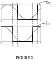
- FIG. 2 illustrates a schematic diagram of values of Î(t) and Q ⁇ (t) in a subcarrier period of a baseband spreading signal according to an embodiment of the present application.
- any of a preset in-phase baseband component Î(t) and a preset quadrature-phase baseband component Q ⁇ (t) of the multiplexed signal S RF ( t ) is of a square waveform, whose starting points are determined by ⁇ ( t ) and ⁇ ' ( t ) .
- the additional phase ⁇ atan2(Q ⁇ (t), Î(t)) and any of the Î(t) and Q ⁇ (t) is of a square waveform
- the value of the additional phase ⁇ may shift at moments when the value of Î(t) or Q ⁇ (t) flips, for example, at t 1 , t 2 , t 3 and t 4 as shown in FIG.2 .
- each of the baseband spreading signals s 1 (t), s 2 (t), s 3 (t), s 4 (t) is a baseband signal with the value of +/-1, there is a total of 16 states of different value combinations for the four baseband spreading signals, such as (1,1,1,1) or (1,-1,-1,1), etc.
- phase-shifting points of the additional phase ⁇ can be calculated. All the phase-shifting points of the additional phase ⁇ constitute a set of the starting points and ending points of segments in a subcarrier period of the baseband spreading signal. That is, the additional phase ⁇ keeps unchanged during a segment of the subcarrier period, and will change in the next segment. Considering that the phase-shifting points of the additional phase ⁇ determined by the 16 value combinations of Î(t) and Q ⁇ (t) may be overlapped, it can be seen, through calculation, that a subcarrier period of the baseband spreading signal can be divided into at most 16 segments for various power ratios of the four baseband spreading signals.
- a subcarrier period of the baseband spreading signal needs to be divided into 12 segments with equal length. That is, for any current time t ⁇ [n T s , (n + 1) T s ), the subcarrier period [n T s , (n + 1) T s ) is further divided into 12 segments with equal length of T s /12.
- an additional phase ⁇ corresponding to the current time can be looked up in the additional phase lookup table, such as in the Table 1 or Table 2.
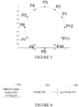
- FIG. 3 illustrates a Fresnel constellation of multiplexed signal S RF ( t ) when the power ratio of the four baseband spreading signals s 1 (t), s 2 (t), s 3 (t), s 4 (t) is 1:3:1:3, according to an embodiment of the present application.
- P 1 ⁇ 6
- the multiplexed signal is a 12-PSK signal, where the constellation points are evenly distributed.
- the constellation may be obtained by rotating the FIG.3 by a certain phase, while the relationship among different phases keeps unchanged.
- FIG. 4 illustrates a block diagram of the generating device of the dual-frequency constant envelope multiplexed signal with four spreading signals, according to an embodiment of the present application.
- the generating device for the dual-frequency constant envelope multiplexed signal with four spreading signals comprises an additional phase lookup table storing unit 410, a lookup unit 420, and a generating unit 430.
- the additional phase lookup table storing unit 410 is configured to store the mentioned additional phase lookup table, which includes additional phases of the in-phase baseband component I(t) and quadrature-phase baseband component Q(t) of the multiplexed signal.
- the additional phase lookup table may be preset as follows and stored in the additional phase lookup table storing unit 410.
- the additional phase lookup table may be configured by dividing a subcarrier period T s of the baseband spreading signal into multiple segments and by determining, at each segment of the multiple segments, an additional phase ⁇ for a state among 16 states of value combination of the four baseband spreading signals s 1 (t), s 2 (t), s 3 (t), s 4 (t) in the constant envelope multiplexed signal, based on the determined power ratio of the four baseband spreading signals s 1 (t), s 2 (t), s 3 (t), s 4 (t).
- the lookup unit 420 is configured to obtain, according to a segment of the subcarrier period of the baseband spreading signal and a state of the value combination of the four baseband spreading signals s 1 (t), s 2 (t), s 3 (t) and s 4 (t) corresponding to the current time, an additional phase ⁇ of a segment of the current time by looking up the additional phase lookup table.
- FIG. 5 illustrates an example of generating the constant envelope multiplexed signal, according to an embodiment of the present application.
- the driving clock of the units is generated through the division or multiplication of the reference frequency clock f 0 .
- the reference frequency clock 20, through the frequency converter 21, is converted into a data driving clock with a frequency f D , which drives the message generator 22 to generate four binary navigation messages. If a pilot channel is required in some implementations, the navigation message of the corresponding channel keeps as being 0 or 1 without changing.
- the reference frequency clock, through frequency converters 23-1, 23-2, 23-3 and 23-4, is converted into the driving clock with frequency of f c 1 , f c 2 , f c3 and f c4 , respectively, which drives spreading modulators 24-1, 24-2, 24-3, and 24-4 to generate four binary spreading sequences, respectively, with spreading code rates of f c 1 , f c 2 , f c 3 and f c 4 . Any of the spreading code rates is the positive integer multiple of f D .
- the four navigation messages generated by the message generator 22 are transmitted into the spreading modulators 24-1, 24-2, 24-3 and 24-4 respectively, to make module-2 additive combination with the spreading sequence.
- the results of the module 2 additive combination are sent into spreading chip waveform generators 26-1, 26-2, 26-3, 26-4 respectively.
- the spreading chip waveform generator is driven by subcarrier driving clocks with the frequency of f sc 1 , f sc 2 , f sc3 and f sc4 , into which the clock 20 is converted through frequency converters 25-1, 25-2, 25-3 and 25-4 respectively.
- the spreading chip waveform generator makes BCS chip waveform assignment to the spreading sequence modulated with navigation message, and the outputs are noted as baseband signals s 1 ( t ) , s 2 ( t ) , s 3 ( t ) , s 4 ( t ) respectively.
- f sc 1 K 1 f c 1
- f sc 2 K 2 f c 2
- f sc 3 K 3 f c 3
- f sc 4 K 4 f c 4
- K 1 , K 2 , K 3 , K 4 are integers greater than or equal to 1.
- the clock 20, through the frequency converter 29, is converted to a driving clock with a frequency of 12 f s , which drives an additional phase table lookup unit 27 and an I-channel trigonometric function generator 31 and a Q-channel trigonometric function generator 32.
- the lookup table is in the form of Table 1 or Table 2.
- P 1 may be set as any phase in [0,2 ⁇ ] .
- the true value of the additional phases in Table 1 or Table 2 may be changed.
- the carrier signal is divided into two branches.
- the carrier signal of a branch 40 and the output of the I-channel trigonometric function generator 31 are sent into a multiplier 33.
- the carrier signal of the other branch 41 after passing through ⁇ / 2 phase shifting circuit 35, turns into a carrier signal with a phase orthogonal to that of the branch 40.
- the carrier signal of the other branch 41 and the output of the Q-channel trigonometric function generator 32 are sent into a multiplier 34.
- the outputs of the two multipliers are sent into an adder 38 so as to generate the constant envelope multiplexed signal 39 according to the application.
- PSD power spectral density
- the upper sideband main lobe 51 with the central frequency of f 1 is 30.69MHz away from the lower sideband main lobe 50 with the central frequency of f 2 , and the bandwidth between the spectral zero-crossing points of the two lobes 50 and 51 is 20.46MHz, corresponding to the design specifications that BPSK-R modulation with 10.23MHz code rate is used for each signal components, and the distance between the central frequency of the two main lobes is 30.96MHz.
- the two signal components sharing the same frequency are combined together, and it is difficult to distinguish the power allocation of each component.
- the receiving method 1 to receive the signal it can be verified the combination of the four signals with the power ratio of 1:3:1:3 is achieved through the multiplexed signal.
- the four baseband spreading signals are multiplexed into a constant envelope multiplexed signal.
- the spreading codes of the four baseband spreading signals are of good orthogonality. In terms of the receiving and processing of the multiplexed signal, not only each signal component of the multiplexed signal independently but also the multiplexed signal as a whole can be received and processed in the receiver.
- Embodiments of the present application described above are mainly involved with the transmission side, that is, with methods and devices for generating the dual-frequency constant envelope multiplexed signal with four spreading signals.
- embodiments of the present application also relate to signals generated through such methods and devices for generating constant envelope multiplexed signal generating as those described above.
- the embodiments of the present application also relate to systems, methods, and devices used for processing, for example, constant envelope multiplexed signals as described above.
- a receiving device for receiving the dual-frequency constant envelope multiplexed signal with four spreading signals generated by the aforementioned generating methods or the generating devices.
- the signal components modulated on the frequency f 1 and the frequency f 2 can be processed respectively.
- a receiving device is provided for the dual-frequency constant envelope multiplexed signal with four spreading signals.
- a signal receiving device 500 includes a receiving unit 510, a demodulation unit 520, and a processing unit 530.
- the receiving unit 510 is configured to receive the constant envelope multiplexed signal.
- the demodulation unit 520 is configured to demodulate a signal component modulated on the frequency f 1 of the received constant envelope multiplexed signal, and to demodulate a signal component modulated on the frequency f 2 of the received constant envelope multiplexed signal.
- the processing unit 530 is configured to obtain the baseband spreading signals S 1 and S 2 according to the demodulated signal component which is modulated on the frequency f 1 , and to obtain the baseband spreading signals S 3 and S 4 according to the demodulated signal component which is modulated on the frequency f 2 .
- FIG. 8 illustrates the schematic diagram of a particular implementation of the receiving device for the dual-frequency constant envelope multiplexed signal with four spreading signals, according to an embodiment of the present application.
- the receiving unit 510 may include an antenna 61;
- the demodulation unit 520 may include a filtering amplification unit 62, a downconverter 63, and an Analog to Digital Converter (ADC) 64;
- the processing unit 530 may include a digital signal processing unit 65.
- ADC Analog to Digital Converter
- the constant envelope multiplexed signal 60 is received from antenna 61. After received by the antenna 61, the received constant envelope multiplexed signal 60 is sent into the filtering amplification unit 62, where the constant envelope multiplexed signal 60 is filtered, in order to resist the strong interference signals and out-of-band noises, and then the constant envelope multiplexed signal 60 is amplified.
- the central frequency of the filtering unit is set near f 1 , with bandwidth greater than or equal to the bandwidth of the signal component s 1 ( t ) or s 2 ( t ) to be received, in order to ensure that enough power of the signal component s 1 ( t ) or s 2 ( t ) passes the filtering unit; similarly, when processing the upper sideband signal component s 3 ( t ) or s 4 ( t ), the central frequency of filter is set near f 2 , with bandwidth greater than or equal to the bandwidth of the signal component s 3 ( t ) or s 4 ( t ) to be received, in order to ensure that enough power of the signal component s 3 ( t ) or s 4 ( t ) passes the filtering unit.
- the filtered and amplified signal from the filtering amplification unit 62 is sent into the downconverter 63, in order to translate the carrier frequency of the signal component to a corresponding Intermediate Frequency (IF); then the signal is sent into the ADC 64 for the sampling and quantization of the signal, and a digital IF signal is obtained.
- IF Intermediate Frequency
- the digital IF signal from the ADC 64 is sent into the digital signal processing unit 65.
- This unit can be implemented by FPGA, ASIC, universal computing unit or the combination of the aforementioned devices, so as to achieve the corresponding acquisition, tracking, demodulation to the baseband signal component to be processed.
- a receiving method for receiving the dual-frequency constant envelope multiplexed signal with four spreading signals generated by the aforementioned constant envelope multiplexed signal generating method or generating device.
- the signal receiving method comprises: receiving the constant envelope multiplexed signal; demodulating the signal component modulated on the frequency f 1 of the received constant envelope multiplexed signal, and demodulating the signal component modulated on the frequency f 2 ; obtaining the baseband spreading signal S 1 and S 2 based on the demodulated signal component which is modulated on the frequency f 1 , and obtaining the baseband spreading signal S 3 and S 4 based on the demodulated signal component which is modulated on the frequency f 2 .
- a receiving device for receiving the dual-frequency constant envelope multiplexed signal with four spreading signals generated by the aforementioned constant envelope multiplexed signal generating method or generating device.
- the received constant envelope multiplexed signal with a central frequency of ( f 1 + f 2 )/2 can be processed as a whole.
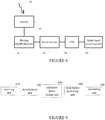
- FIG. 9 illustrates a receiving device for the dual-frequency constant envelope multiplexed signal with four spreading signals, according to another embodiment of the present application.
- the receiving device comprises a receiving unit 610, a demodulation unit 620, an additional phase looking up unit 630, a local replica generating unit 640 and a calculating unit 650.
- the receiving unit 610 is configured to receive the constant envelope multiplexed signal.
- the additional phase looking up unit 630 is configured to obtain an additional phase ⁇ corresponding to each state among states of value combination of the four baseband spreading signals s 1 (t), s 2 (t), s 3 (t), s 4 (t) based on the additional phase lookup table.
- the local replica generating unit 640 is configured to generate a local replica ⁇ i ( t ) of an in-phase baseband signal and a local replica Q ⁇ i ( t ) of a quadrature-phase baseband signal corresponding to each state based on the obtained additional phase ⁇ .
- the calculating unit 650 is configured to calculate a correlation between the generated ⁇ i ( t ) and Q ⁇ i ( t ) corresponding to each state with the demodulated baseband signal, so as to determine the baseband spreading signals s 1 (t), s 2 (t), s 3 (t), s 4 (t) of the demodulated baseband signal.
- the combination of four baseband signal values [S 1 , S 2 , S 3 , S 4 ] may have up to 16 combination states.
- the calculating unit 650 may, corresponding to each of the 16 combination states, calculate a correlation between the in-phase baseband component local replica and the quadrature-phase baseband component local replica with the in-phase baseband component and the quadrature-phase baseband component obtained from the demodulation unit 640, so as to determine values of the received first baseband signal S 1 , the second baseband signal S 2 , the third baseband signal S 3 , and the forth baseband signal S 4 .
- the acquisition and tracking of the constant envelope multiplexed signal can be achieved.
- the receiving device for the dual-frequency constant envelope multiplexed signal with four spreading signals is illustrated, according to another embodiment of the present application.
- the constant envelope multiplexed signal is received by the receiving unit 610 of the receiver.
- the received constant envelope multiplexed signal from the antenna of the receiving unit 610 is sent into the filtering amplification unit of the receiving unit 610, for filtering the constant envelope multiplexed signal to resist the strong interference signals and out-of-band noises, and for amplifying the constant envelope multiplexed signal.
- the central frequency of filtering unit is set near ( f 1 + f 2 )/2, with a bandwidth greater than or equal to 2 f s , to ensure that enough power of the whole multiplexed signal passes the filtering unit. If the filtering unit can designed appropriately, it is suggested to ensure that the first main lobe power of every signal component passes the filtering unit.
- the filtered and amplified signal from the filtering amplification unit of the receiving unit 610 is sent into the downconverter of the demodulation 620, to convert the carrier frequency of the signal component to an Intermediate Frequency (IF); then the signal is sent into the ADC of the demodulation unit 620 for the sampling and quantization of the signal, to obtain a digital IF signal.
- IF Intermediate Frequency
- the digital IF signal from the ADC of the demodulation unit 620 is sent into the digital signal processing unit of the demodulation unit 620.
- This unit can be implemented by FPGA, ASIC, universal computing unit or the combination of the aforementioned devices.
- the digital IF signal is multiplied by the in-phase carrier and quadrature-phase carrier generated by the receiver, in order to remove the IF and Doppler of the digital signal, so as to obtain the receiver in-phase baseband signal SI(t) and the receiver quadrature-phase baseband signal SQ(t).
- the digital signal processing unit of the demodulation unit 620 is configured to generate spreading sequences of four signals with spreading chip waveform assignment. According to all the possible value combinations of the binary baseband local signal replica of the four signals, the in-phase baseband waveform local replica ⁇ i ( t ) and the quadrature-phase baseband waveform local replica Q ⁇ i ( t ) are generated by the digital signal processing unit of the demodulation unit 620 corresponding to each combination, at each epoch.
- phase additional phase looking up unit 630 obtains the additional phase ⁇ i corresponding to the current time by searching the phase lookup table.
- the calculating unit 650 selects an optimal in-phase combination correlation value I' and an optimal quadrature-phase combination correlation value Q i ' to be a group of in-phase combination correlation value I i ' and quadrature-phase combination correlation value Q', the value I i ′ 2 + Q i ′ 2 of which is the maximum among all the groups, so as to determine the baseband spreading signal s 1 (t), s 2 (t), s 3 (t), S4 (t), and to process with I ' and Q' through traditional acquisition method and tracking loop.
- Embodiments of the present application may be implemented by hardware, software or the combination thereof.
- An aspect of the present application provides a program including executable instructions to implement the constant envelope multiplexed signal generating method, generating device, the constant envelope multiplexed signal receiving method, receiving device according to embodiments of the present application.
- the program can be stored in storage of any form, such as optical or magnetic readable media, chip, ROM, PROM, or any form of volatile or non-volatile memory device.
- a machine-readable storage is provided for storing the program.
Landscapes
- Engineering & Computer Science (AREA)
- Radar, Positioning & Navigation (AREA)
- Remote Sensing (AREA)
- Computer Networks & Wireless Communication (AREA)
- Signal Processing (AREA)
- Physics & Mathematics (AREA)
- General Physics & Mathematics (AREA)
- Digital Transmission Methods That Use Modulated Carrier Waves (AREA)
- Circuits Of Receivers In General (AREA)
- Position Fixing By Use Of Radio Waves (AREA)
Claims (8)
- Verfahren zum Erzeugen eines Zweifrequenz-Konstanthüllkurvenmultiplexsignals mit vier Spreizsignalen, bei dem die vier Basisband-Spreizsignale s1(t), s2(t), s3(t), s4(t) jeweils auf eine Frequenz f1 und eine Frequenz f2 moduliert werden, um das Konstanthüllkurvenmultiplexsignal auf einer Funkträgerfrequenz fP = (f1 + f2)/2 zu erzeugen, wobei die Signale s1(t) und s2(t) auf die Frequenz f1 mit zueinander orthogonalen Trägerphasen moduliert sind, und die Signale s3(t) und s4(t) auf die Frequenz f2 mit zueinander orthogonalen Trägerphasen moduliert sind, f1 > f2, wobei das Verfahren ferner umfasst:Bestimmen eines Leistungsverhältnisses, das den vier Basisband-Spreizsignalen s1(t), s2(t), s3(t), s4(t) in dem Konstanthüllkurvenmultiplexsignal zugeordnet ist;Speichern einer Zusatzphasennachschlagetabelle, wobei die Tabelle Zusatzphasen einer phasengleichen Basisbandkomponente I(t) und einer Quadraturphasen-Basisbandkomponente Q(t) des Konstanthüllkurvenmultiplexsignals umfasst, und die Tabelle auf der Grundlage des bestimmten Leistungsverhältnisses der vier Basisband-Spreizsignale s1(t), s2(t), s3(t), s4(t) durch eine Unterteilung einer Subträgerperiode Ts des Basisband-Spreizsignals in mehrere Segmente und eine Bestimmung einer Zusatzphase θ für einen Zustand unter 16 Zuständen einer Wertekombination der vier Basisband-Spreizsignale s1(t), s2(t), s3(t), s4(t) in dem Konstanthüllkurvenmultiplexsignal an jedem Segment der mehreren Segmente eingerichtet ist;Erlangen einer Zusatzphase θ eines Segments der aktuellen Zeit durch Nachschlagen in der Zusatzphasennachschlagetabelle gemäß einem Segment der Subträgerperiode des Basisband-Spreizsignals und einem der aktuellen Zeit entsprechenden Zustand der Wertekombination der vier Basisband-Spreizsignale s1(t), s2(t), s3(t), s4(t);Erzeugen einer phasengleichen Basisbandkomponente I(t) und einer Quadraturphasen-Basisbandkomponente Q(t) des Konstanthüllkurvenmultiplexsignals, und zum Erzeugen des Konstanthüllkurvenmultiplexsignals SRF(t) auf der Grundlage der erlangten Zusatzphase θ, wobei


 wobei A die Amplitude des Konstanthüllkurvenmultiplexsignals SRF(t) ist, undwobei das Leistungsverhältnis der vier Basisband-Spreizsignale s1(t), s2(t), s3(t), s4(t) 1:3:1:3 beträgt, und die Subträgerperiode Ts des Basisband-Spreizsignals in 12 Segmente gleicher Länge unterteilt ist, und die Zusatzphasennachschlagetabelle in der Form von Tabelle 1 oder Tabelle 2 vorliegt:
Tabelle 1 VS1 VS2 VS3 VS4 VS5 VS6 VS7 VS8 VS9 VS10 VS11 VS12 VS13 VS14 VS15 VS16 s 1(t) 1 1 1 1 1 1 1 1 -1 -1 -1 -1 -1 -1 -1 -1 s 2(t) 1 1 -1 -1 1 1 -1 -1 1 1 -1 -1 1 1 -1 -1 s 3(t) 1 1 1 1 -1 -1 -1 -1 1 1 1 1 -1 -1 -1 -1 s4(t) 1 -1 1 -1 1 -1 1 -1 1 -1 1 -1 1 -1 1 -1 t' = t mod Ts θ t'∈ [0,Ts /12) P2 P12 P12 P10 P3 P5 P1 P9 P3 P7 P11 P9 P4 P6 P6 P8 [Ts /12,2Ts /12) P2 P6 P12 P10 P3 P5 P1 P9 P3 P7 P11 P9 P4 P6 P12 P8 [2Ts f/12,3Ts /12) P2 P6 P12 P10 P3 P5 P1 P3 P9 P7 P11 P9 P4 P6 P12 P8 [3Ts /12,4Ts /12) P8 P6 P12 P4 P3 P5 P1 P3 P9 P7 P11 P9 P10 P6 P12 P2 [4Ts /2,5Ts /12) P8 P6 P12 P4 P9 P5 P1 P3 P9 P7 P11 P3 P10 P6 P12 P2 [5Ts /12.6Ts /12) P8 P6 P6 P4 P9 P5 P1 P3 P9 P7 P11 P3 P10 P12 P12 P2 [6Ts /12,7Ts /12) P8 P6 P6 P4 P9 P11 P7 P3 P9 P1 P5 P3 P10 P12 P12 P2 [7Ts /12,8Ts /12) P8 P12 P6 P4 P9 P11 P7 P3 P9 P1 P5 P3 P10 P12 P6 P2 [8Ts /12,9Ts /12) P8 P12 P6 P4 P9 P11 P7 P9 P3 P1 P5 P3 P10 P12 P6 P2 [9Ts /12,10Ts /12) P2 P12 P6 P10 P9 P11 P7 P9 P3 P1 P5 P3 P4 P12 P6 P8 [10Ts /12,11Ts /12) P2 P12 P6 P10 P3 P11 P7 P9 P3 P1 P5 P9 P4 P12 P6 P8 [11Ts /12,Ts ) P2 P12 P12 P10 P3 P11 P7 P9 P3 P1 P5 P9 P4 P6 P6 P8 Tabelle 2 wobei VSi,i = 1, 2, 3 ..., 16 für 16 Zustände von Wertekombinationen der vier Basisband-Spreizsignale s1(t), s2(t), s3(t), s4(t) steht; PK, K = 1, 2, 3 ..., 12 für den Wert der Zusatzphase θ steht, und wobeiVS1 VS2 VS3 VS4 VS5 VS6 VS7 VS8 VS9 VS10 VS11 VS12 VS13 VS14 VS15 VS16 s 1(t) 1 1 1 1 1 1 1 1 -1 -1 -1 -1 -1 -1 -1 -1 s 2(t) 1 1 -1 -1 1 1 -1 -1 1 1 -1 -1 1 1 -1 -1 s 3(t) 1 1 1 1 -1 -1 -1 -1 1 1 1 1 -1 -1 -1 -1 s 4(t) 1 -1 1 -1 1 -1 1 -1 1 -1 1 -1 1 -1 1 -1 t' = t mod Ts θ t' [0,Ts /12) P1 P12 P12 P11 P3 P4 P2 P9 P3 P8 P10 P9 P5 P6 P6 P7 [Ts /12,2Ts /12) P1 P12 P12 P11 P3 P4 P2 P3 P9 P8 P10 P9 P5 P6 P6 P7 [2Ts /12,3Ts /12) P1 P6 P12 P11 P3 P4 P2 P3 P9 P8 P10 P9 P5 P6 P12 P7 [3Ts 12,4Ts /12) P7 P6 P12 P5 P3 P4 P2 P3 P9 P8 P10 P9 P11 P6 P12 P1 [4Ts /12,5Ts /12) P7 P6 P6 P5 P3 P4 P2 P3 P9 P8 P10 P9 P11 P12 P12 P1 [5Ts /12.6Ts /12) P7 P6 P6 P5 P9 P4 P2 P3 P9 P8 P10 P3 P11 P12 P12 P1 [6Ts /12,7Ts /12) P7 P6 P6 P5 P9 P10 P8 P3 P9 P2 P4 P3 P11 P12 P12 P1 [7Ts /12,8Ts /12) P7 P6 P6 P5 P9 P10 P8 P9 P3 P2 P4 P3 P11 P12 P12 P1 [8Ts /12,9Ts /12) P7 P12 P6 P5 P9 P10 P8 P9 P3 P2 P4 P3 P11 P12 P6 P1 [9Ts /12,10Ts /12) P1 P12 P6 P11 P9 P10 P8 P9 P3 P2 P4 P3 P5 P12 P6 P7 [10Ts /12,11Ts /12) P1 P12 P12 P11 P9 P10 P8 P9 P3 P2 P4 P3 P5 P6 P6 P7 [11Ts /12,Ts ) P1 P12 P12 P11 P3 P10 P8 P9 P3 P2 P4 P9 P5 P6 P6 P7 
- Vorrichtung zum Erzeugen eines Zweifrequenz-Konstanthüllkurvenmultiplexsignals mit vier Spreizsignalen, bei dem die vier Basisband-Spreizsignale s1(t), s2(t), s3(t), s4(t) jeweils auf eine Frequenz f1 und eine Frequenz f2 moduliert sind, um das Konstanthüllkurvenmultiplexsignal auf einer Funkträgerfrequenz fP = (f1 + f2)/2 zu erzeugen, wobei die Signale s1(t) und s2(t) auf die Frequenz f1 mit zueinander orthogonalen Trägerphasen moduliert sind, und die Signale s3(t) und s4(t) auf die Frequenz f2 mit zueinander orthogonalen Trägerphasen moduliert sind, f1 > f2, wobei die Vorrichtung ferner umfasst:eine Zusatzphasennachschlagetabellenspeichereinheit zum Speichern der Zusatzphasennachschlagetabelle, wobei die Tabelle Zusatzphasen einer phasengleichen Basisbandkomponente I(t) und einer Quadraturphasen-Basisbandkomponente Q(t) des Konstanthüllkurvenmultiplexsignals umfasst, und die Tabelle auf der Grundlage des bestimmten Leistungsverhältnisses der vier Basisband-Spreizsignale s1(t), s2(t), s3(t), s4(t) durch eine Unterteilung einer Subträgerperiode TS des Basisband-Spreizsignals in mehrere Segmente und eine Bestimmung einer Zusatzphase θ für einen Zustand unter 16 Zuständen einer Wertekombination der vier Basisband-Spreizsignale s1(t), s2(t), s3(t), s4(t) im Konstanthüllkurvenmultiplexsignal an jedem Segment der mehreren Segmente eingerichtet ist;eine Nachschlageeinheit zum Erlangen einer Zusatzphase θ eines Segments der aktuellen Zeit durch Nachschlagen in der Zusatzphasennachschlagetabelle gemäß einem Segment der Subträgerperiode des Basisband-Spreizsignals und einem der aktuellen Zeit entsprechenden Zustand der Wertekombination der vier Basisband-Spreizsignale s1(t), s2(t), s3(t) und s4(t);eine Erzeugungseinheit zum Erzeugen einer phasengleichen Basisbandkomponente I(t) und einer Quadraturphasen-Basisbandkomponente Q(t) des Konstanthüllkurvenmultiplexsignals und zum Erzeugen des Konstanthüllkurvenmultiplexsignal SRF(t) auf der Grundlage der erlangten Zusatzphase θ, wobei


 wobei A die Amplitude des Konstanthüllkurvenmultiplexsignals SRF(t) ist, undwobei das Leistungsverhältnis der vier Basisband-Spreizsignale s1(t), s2(t), s3(t), s4(t) 1:3:1:3 beträgt, und die Subträgerperiode TS des Basisband-Spreizsignals in 12 Segmente gleicher Länge unterteilt ist, und die in der Zusatzphasennachschlagetabellenspeichereinheit gespeicherte Zusatzphasennachschlagetabelle in der Form von Tabelle 1 oder Tabelle 2 vorliegt:
Tabelle 1 VS1 VS2 VS3 VS4 VS5 VS6 VS7 VS8 VS9 VS10 VS11 VS12 VS13 VS14 VS15 VS16 s 1(t) 1 1 1 1 1 1 1 1 -1 -1 -1 -1 -1 -1 -1 -1 s 2(t) 1 1 -1 -1 1 1 -1 -1 1 1 -1 -1 1 1 -1 -1 s 3 (t) 1 1 1 1 -1 -1 -1 -1 1 1 1 1 -1 -1 -1 -1 s 4(t) 1 -1 1 -1 1 -1 1 -1 1 -1 1 -1 1 -1 1 -1 t'=t mod Ts θ t' ∈ [0,Ts /12) P2 P12 P12 P10 P3 P5 P1 P9 P3 P7 P11 P9 P4 P6 P6 P8 [Ts /12.2Ts /12) P2 P6 P12 P10 P3 P5 P1 P9 P3 P7 P11 P9 P4 P6 P12 P8 [2Ts /12,3Ts /12) P2 P6 P12 P10 P3 P5 P1 P3 P9 P7 P11 P9 P4 P6 P12 P8 [3Ts /12,4Ts /12) P8 P6 P12 P4 P3 P5 P1 P3 P9 P7 P11 P9 P10 P6 P12 P2 [4Ts /12,5Ts ,/12) P8 P6 P12 P4 P9 P5 P1 P3 P9 P7 P11 P3 P10 P6 P12 P2 [5Ts /12,6Ts /12) P8 P6 P6 P4 P9 P5 P1 P3 P9 P7 P11 P3 P10 P12 P12 P2 [6Ts /12,7Ts /12) P8 P6 P6 P4 P9 P11 P7 P3 P9 P1 P5 P3 P10 P12 P12 P2 [7Ts /12,8Ts /12) P8 P12 P6 P4 P9 P11 P7 P3 P9 P1 P5 P3 P10 P12 P6 P2 [8Ts /12,9Ts /12) P8 P12 P6 P4 P9 P11 P7 P9 P3 P1 P5 P3 P10 P12 P6 P2 [9Ts /12,10Ts /12) P2 P12 P6 P10 P9 P11 P7 P9 P3 P1 P5 P3 P4 P12 P6 P8 [10Ts /12,11Ts /12) P2 P12 P6 P10 P3 P11 P7 P9 P3 P1 P5 P9 P4 P12 P6 P8 [11Ts /12,Ts ) P2 P12 P12 P10 P3 P11 P7 P9 P3 P1 P5 P9 P4 P6 P6 P8 Tabelle 2 wobei VSi,i = 1, 2, 3 ..., 16 für 16 Zustände von Wertekombinationen der vier Basisband-Spreizsignale si(t), s2(t), s3(t), s4(t) steht; PK, K = 1, 2, 3 ..., 12 für den Wert der Zusatzphase θ steht, und wobeiVS1 VS2 VS3 VS4 VS5 VS6 VS7 VS8 VS9 VS10 VS11 VS12 VS13 VS14 VS15 VS16 s 1(t) 1 1 1 1 1 1 1 1 -1 -1 -1 -1 -1 -1 -1 -1 s2 (t) 1 1 -1 -1 1 1 -1 -1 1 1 -1 -1 1 1 -1 -1 s3 (t) 1 1 1 1 -1 -1 -1 -1 1 1 1 1 -1 -1 -1 -1 s4 (t) 1 -1 1 -1 1 -1 1 -1 1 -1 1 -1 1 -1 1 -1 t'=t modTs θ t' [0,Ts /12) P1 P12 P12 P11 P3 P4 P2 P9 P3 P8 P10 P9 P5 P6 P6 P7 [Ts /12,2Ts /12) P1 P12 P12 P11 P3 P4 P2 P3 P9 P8 P10 P9 P5 P6 P6 P7 [2Ts /12,3Ts /12) P1 P6 P12 P11 P3 P4 P2 P3 P9 P8 P10 P9 P5 P6 P12 P7 [3Ts /12,Ts /12) P7 P6 P12 P5 P3 P4 P2 P3 P9 P8 P10 P9 P11 P6 P12 P1 [4Ts /12,5Ts /12) P7 P6 P6 P5 P3 P4 P2 P3 P9 P8 P10 P9 P11 P12 P12 P1 [5Ts /12,6Ts /12) P7 P6 P6 P5 P9 P4 P2 P3 P9 P8 P10 P3 P11 P12 P12 P1 [6Ts /12,7Ts /12) P7 P6 P6 P5 P9 P10 P8 P3 P9 P2 P4 P3 P11 P12 P12 P1 [7Ts /12,8Ts /12) P7 P6 P6 P5 P9 P10 P8 P9 P3 P2 P4 P3 P11 P12 P12 P1 [8Ts /12,9Ts /12) P7 P12 P6 P5 P9 P10 P8 P9 P3 P2 P4 P3 P11 P12 P6 P1 [9Ts /12,10Ts /12) P1 P12 P6 P11 P9 P10 P8 P9 P3 P2 P4 P3 P5 P12 P6 P7 [10Ts ,/12,11Ts /12) P1 P12 P12 P11 P9 P10 P8 P9 P3 P2 P4 P3 P5 P6 P6 P7 [11Ts /12,Ts ) P1 P12 P12 P11 P3 P10 P8 P9 P3 P2 P4 P9 P5 P6 P6 P7 
- Signalempfangsvorrichtung, die dazu eingerichtet ist, das durch das Verfahren nach Anspruch 1 erzeugte Konstanthüllkurvenmultiplexsignal zu empfangen, oder die Vorrichtung zur Erzeugung des Zweifrequenz-Konstanthüllkurvenmultiplexsignals mit vier Spreizsignalen nach Anspruch 2, wobei dieselbe Zusatzphasennachschlagetabelle in der Form von Tabelle 1 oder Tabelle 2 in der Signalempfangsvorrichtung wie in der Vorrichtung zum Erzeugen des Zweifrequenz-Konstanthüllkurvenmultiplexsignals mit vier Spreizsignalen nach Anspruch 2 gespeichert ist, und die Signalempfangsvorrichtung umfasst:eine Empfangseinheit zum Empfangen des Konstanthüllkurvenmultiplexsignals;eine Demodulationseinheit zum Demodulieren des Konstanthüllkurvenmultiplexsignals mit einer Mittelfrequenz von fP = (f1 + f2)/2, um das demodulierte Basisbandsignal zu erlangen;eine Zusatzphasennachschlageinheit zum Erlangen, auf der Grundlage der Zusatzphasennachschlagetabelle, einer Zusatzphase θ, die jedem Zustand unter den Zuständen der Wertekombination der vier Basisband-Spreizsignale s1(t), s2(t), s3(t), s4(t) entspricht;eine Lokalnachbildungs-Erzeugungseinheit zum Erzeugen, auf der Grundlage der erlangten Zusatzphase θ, einer Lokalnachbildung Ĩi (t) eines phasengleichen Basisbandsignals und einer Lokalnachbildung Q̃i (t) eines Quadraturphasen-Basisbandsignals, die jedem Zustand entsprechen; undeine Berechnungseinheit zum Berechnen einer Korrelation zwischen den jedem Zustand entsprechenden erzeugten Ĩi (t) und Q̃i (t) mit dem demodulierten Basisbandsignal, um die Basisband-Spreizsignale s1(t), s2(t), s3(t), s4(t) des demodulierten Basisbandsignals zu bestimmen, um die Erfassung und Verfolgung des Konstanthüllkurvenmultiplexsignals zu erreichen.
- Signalempfangsverfahren zum Empfangen des durch das Verfahren nach Anspruch 1 erzeugten Konstanthüllkurvenmultiplexsignals oder der Vorrichtung zum Erzeugen des Zweifrequenz-Konstanthüllkurvenmultiplexsignals mit vier Spreizsignalen nach Anspruch 2,
wobei das Signalempfangsverfahren umfasst:Speichern derselben Zusatzphasennachschlagetabelle 1 in der Form von Tabelle 1 oder Tabelle 2 wie bei der Vorrichtung zum Erzeugen des Zweifrequenz-Konstanthüllkurvenmultiplexsignals mit vier Spreizsignalen nach Anspruch 2;Empfangen des Konstanthüllkurvenmultiplexsignals;Demodulieren des empfangenen Konstanthüllkurvenmultiplexsignals durch eine Mittelfrequenz von fP = (f1 + f2) /2, um das demodulierte Basisbandsignal zu erlangen;Erlangen, auf der Grundlage der Zusatzphasennachschlagetabelle, einer Zusatzphase θ, die jedem Zustand unter den Zuständen der Wertekombination der vier Basisband-Spreizsignale s1(t), s2(t), s3(t), s4(t) entspricht;Erzeugen, auf der Grundlage der erlangten Zusatzphase θ, einer Lokalnachbildung Ĩi (t) eines phasengleichen Basisbandsignals und einer Lokalnachbildung Q̃i (t) eines Quadraturphasen-Basisbandsignals, die jedem Zustand entsprechen;Berechnen einer Korrelation zwischen den jedem Zustand entsprechenden erzeugten Ĩi (t) und Q̃i (t) mit dem demodulierten Basisbandsignal, um die Basisband-Spreizsignale s1(t), s2(t), s3(t), s4(t) des demodulierten Basisbandsignals zu bestimmen, um die Beschaffung und Verfolgung des Konstanthüllkurvenmultiplexsignals zu erreichen. - Signalempfangsvorrichtung nach Anspruch 3, wobeidie Empfangseinheit zum Empfang, Filterung und Verstärkung des Konstanthüllkurvenmultiplexsignals eingerichtet ist, wobei eine Mittelfrequenz der Filterung und Verstärkung auf (f1 + f2)/2 eingestellt ist;die Demodulationseinheit dazu eingerichtet ist, eine Trägerfrequenz der zu verarbeitenden Signalkomponente in eine entsprechende Zwischenfrequenz umzuwandeln, die Signalkomponente von Analog nach Digital durch Abtasten und Quantisieren des Signals umzuwandeln, und ein phasengleiches Empfänger-Basisbandsignal SI(t) und ein Empfänger-Quadraturphasen-Basisbandsignal SQ(t) durch Multiplizieren des umgewandelten digitalen Zwischenfrequenzsignals mit jeweils einem phasengleichen Träger und einem Quadraturphasen-Träger zu erlangen;die Zusatzphasennachschlageinheit dazu eingerichtet ist, eine Spreizfolge aus vier Basisband-Spreizsignalen mit einer Spreizchip-Wellenformzuordnung zu erzeugen und auf der Grundlage von allen möglichen Wertekombinationen der binären Basisbandsignal-Lokalsignalnachbildung der vier Basisband-Spreizsignale eine phasengleiche Basisbandsignal-Lokalnachbildung Ĩi (t) und ein Quadraturphasen-Basisbandsignal-Lokalnachbildung Q̃i (t) zu jeder Epoche zu erzeugen, die jeder Kombination in der Zusatzphasennachschlagetabelle entsprechen, wobei die Anzahl der Wertekombinationen als g, g = 2 N bezeichnet ist, wobei es N Datenkanäle gibt, und in einem Sonderfall Si = {s̃ 1,s̃ 2,s̃ 3,s̃ 4} unter den g Wertekombinationen die Erzeugungsregel von Ĩi (t) and Q̃i (t) in der Sendevorrichtung dieselbe ist, und die Zusatzphase θi der aktuellen Zeit durch Nachschlagen in der Zusatzphasennachschlagetabelle zu erlangen;die Lokalnachbildungs-Erzeugungseinheit dazu eingerichtet ist, die phasengleiche Basisbandsignal-Lokalnachbildung Ĩi (t) und die Quadraturphasen-Basisbandsignal-Lokalnachbildung Q̃i (t) zu erzeugen, sodass

 die Berechnungseinheit zum Erlangen der i-ten (i=1, 2, ...., g) Gruppe eines ersten phasengleichen Korrelationswerts corr1Ii und eines ersten Quadraturphasen-Korrelationswerts corr1Qi durch Multiplikation der i-ten (i=1, 2, ...., g) Gruppe der phasengleichen Basisbandsignal-Lokalnachbildung Ĩi (t) mit dem phasengleichen Basisbandsignal SI(t) und dem Quadraturphasen-Basisbandsignal SQ(t) und Senden der Multiplikationsergebnisse an einen Integrations- und Dumpingfilter zur kohärenten Integration mit einer Dauer von TI, und zum Erlangen der i-ten (i=1, 2, ...., g) Gruppe des zweiten phasengleichen Korrelationswerts corr2Ii und des Quadraturphasen-Korrelationswerts corr2Qi durch Multiplikation jeder Gruppe der Quadraturphasen-Basisbandsignal-Lokalnachbildung Q̃i (t) mit dem phasengleichen Basisbandsignal SI(t) und dem Quadraturphasen-Basisbandsignal SQ(t) und Senden der Multiplikationsergebnisse in den Integrations- und Dumpingfilter für die kohärente Integration mit einer Dauer von TI;zum Erlangen der i-ten (i=1, 2, ...., g) Gruppe des phasengleichen Kombinationskorrelationswerts I'i und des Quadraturphasen-Kombinationskorrelationswerts Q' i durch Kombinieren des ersten phasengleichen Korrelationswerts corr1Ii und des ersten Quadraturphasen-Korrelationswerts corr1Qi der i-ten Gruppe mit dem zweiten phasengleichen Korrelationswert corr2Ii und dem zweiten Quadraturphasen-Korrelationswert corr2Qi der i-ten Gruppe als:
 zum Auswählen eines optimalen phasengleichen Kombinationskorrelationswerts I' und eines optimalen Quadraturphasen-Kombinationskorrelationswerts Q' als eine Gruppe von phasengleichen Kombinationskorrelationswerten Ii' und Quadraturphasen-Kombinationskorrelationswerten Qi', deren Wert
- Signalempfangsverfahren nach Anspruch 4, ferner mit:Empfangen, Filtern und Verstärken des Konstanthüllkurvenmultiplexsignals, wobei das Filtern und Verstärken bei der Mittelfrequenz von (f1 + f2) /2 durchgeführt wird;Umwandeln einer Trägerfrequenz der zu verarbeitenden Signalkomponente in eine entsprechende Zwischenfrequenz, und Umwandeln der Signalkomponente von Analog nach Digital durch Abtasten und Quantisieren des Signals, und Erlangen eines phasengleichen Empfänger-Basisbandsignals SI(t) und eines Empfänger-Quadraturphasen-Basisbandsignals SQ(t) durch Multiplizieren des umgewandelten digitalen Zwischenfrequenzsignals mit jeweils einem phasengleichen Träger und einem Quadraturphasen-Träger;Erzeugen einer Spreizfolge aus vier Basisband-Spreizsignalen mit einer Spreizchip-Wellenformzuordnung, und Erzeugen, auf der Grundlage von allen der möglichen Wertekombinationen der binären Basisband-Lokalsignalnachbildung der vier Basisband-Spreizsignale, einer phasengleichen Basisbandsignal-Lokalnachbildung Ĩi (t) und einer Quadraturphasen-Basisbandsignal-Lokalnachbildung Q̃i (t), die jeder Kombination entsprechen, zu jeder Epoche, wobei die Anzahl von Wertekombinationen als g, g=2 N bezeichnet wird, wobei es N Datenkanäle gibt, und in einem Sonderfall Si = {s̃ 1,s̃ 2,s̃ 3,s̃ 4} unter den g-Wertekombinationen die Erzeugungsregel von Ĩi (t) und Q̃i (t) in der Sendevorrichtung dieselbe ist, und zum Erlangen der Zusatzphase θi der aktuellen Zeit durch Nachschlagen in der Zusatzphasennachschlagetabelle ist;Erzeugen der phasengleichen Basisbandsignal-Lokalnachbildung Ĩi (t) und der Quadraturphasen-Basisbandsignal-Lokalnachbildung Q̃i (t), sodass

 Erlangen der i-ten (i=1, 2, ...., g) Gruppe eines ersten phasengleichen Korrelationswerts corr1Ii und eines ersten Quadraturphasen-Korrelationswerts corr1Qi durch Multiplizieren der i-ten (i=1, 2, ...., g) Gruppe der phasengleichen Basisbandsignal-Lokalnachbildung Ĩi (t) mit dem phasengleichen Basisbandsignal SI(t) und dem Quadraturphasen-Basisbandsignal SQ(t) und Senden der Multiplikationsergebnisse in einen Integrations- und Dumpingfilter zur kohärenten Integration mit einer Dauer von TI und zum Erlangen der i-ten (i=1, 2, ...., g) Gruppe des zweiten phasengleichen Korrelationswerts corr2Ii und des Quadraturphasen-Korrelationswerts corr2Qi durch Multiplizieren jeder Gruppe der Quadraturphasen-Basisbandsignal-Lokalnachbildung Q̃i (t) mit dem phasengleichen Basisbandsignal SI(t) und dem Quadraturphasen-Basisbandsignal SQ(t) und Senden der Multiplikationsergebnisse in den Integrations- und Dumpingfilter für die kohärente Integration mit einer Dauer von TI;Erlangen der i-ten (i=1, 2, ...., g) Gruppe eines phasengleichen Kombinationskorrelationswerts I'i und eines Quadraturphasen-Kombinationskorrelationswerts Q' i durch Kombinieren des ersten phasengleichen Korrelationswerts corr1Ii und des ersten Quadraturphasen-Korrelationswerts corr1Qi der i-ten Gruppe mit dem zweiten phasengleichen Korrelationswert corr2Ii und dem zweiten Quadraturphasen-Korrelationswert corr2Qi der i-ten Gruppe als:
 Auswählen eines optimalen phasengleichen Kombinationskorrelationswerts I' und eines optimalen Quadraturphasen-Kombinationskorrelationswerts Q' als eine Gruppe von phasengleichen Kombinationskorrelationswerten Ii' und Quadraturphasen-Kombinationskorrelationswerten Qi', deren Wert
- Programm mit ausführbaren Anweisungen zur Implementierung des Signalerzeugungsverfahrens nach Anspruch 1 oder des Signalempfangsverfahrens nach einem der Ansprüche 4 und 6.
- Maschinenlesbarer Speicher zum Speichern eines Programms nach Anspruch 7.
Applications Claiming Priority (2)
| Application Number | Priority Date | Filing Date | Title |
|---|---|---|---|
| CN201210484613.8A CN103023598B (zh) | 2012-11-23 | 2012-11-23 | 双频四分量扩频信号的恒包络复用方法、装置及接收方法 |
| PCT/CN2013/087732 WO2014079390A1 (zh) | 2012-11-23 | 2013-11-22 | 双频四分量扩频信号的恒包络信号生成方法和装置、接收方法和装置 |
Publications (3)
| Publication Number | Publication Date |
|---|---|
| EP2924899A1 EP2924899A1 (de) | 2015-09-30 |
| EP2924899A4 EP2924899A4 (de) | 2016-07-20 |
| EP2924899B1 true EP2924899B1 (de) | 2019-12-25 |
Family
ID=47971770
Family Applications (1)
| Application Number | Title | Priority Date | Filing Date |
|---|---|---|---|
| EP13856588.2A Active EP2924899B1 (de) | 2012-11-23 | 2013-11-22 | Verfahren und vorrichtung zur konstanten hüllkurvensignalerzeugung sowie empfangsverfahren und -vorrichtung für doppelfrequenz-vierkomponenten-spreizspektrumsignale |
Country Status (13)
| Country | Link |
|---|---|
| US (1) | US9680594B2 (de) |
| EP (1) | EP2924899B1 (de) |
| JP (1) | JP6095082B2 (de) |
| KR (1) | KR101728258B1 (de) |
| CN (2) | CN103023598B (de) |
| AU (1) | AU2013350180B2 (de) |
| BR (1) | BR112015011874B1 (de) |
| CA (1) | CA2892443C (de) |
| MY (1) | MY167961A (de) |
| NZ (1) | NZ709287A (de) |
| RU (1) | RU2628529C2 (de) |
| WO (1) | WO2014079390A1 (de) |
| ZA (1) | ZA201504473B (de) |
Families Citing this family (19)
| Publication number | Priority date | Publication date | Assignee | Title |
|---|---|---|---|---|
| CN102694569B (zh) * | 2012-06-07 | 2014-05-14 | 清华大学 | 导航信号的恒包络复用方法、生成装置以及接收方法 |
| CN103023598B (zh) | 2012-11-23 | 2016-03-30 | 清华大学 | 双频四分量扩频信号的恒包络复用方法、装置及接收方法 |
| CN104702311B (zh) | 2013-12-06 | 2017-08-11 | 清华大学 | 扩频信号的生成方法、生成装置、接收方法和接收装置 |
| US9184973B2 (en) * | 2014-01-10 | 2015-11-10 | Deere & Company | Method and receiver for receiving a binary offset carrier composite signal |
| CN103869335B (zh) * | 2014-02-24 | 2015-01-07 | 中国科学院光电研究院 | 一种复合载波导航信号的生成方法 |
| WO2017031754A1 (en) * | 2015-08-27 | 2017-03-02 | Telefonaktiebolaget Lm Ericsson (Publ) | Method and dual band radio receiver for handling analog dual band radio signal |
| CN105589083A (zh) * | 2015-12-04 | 2016-05-18 | 航天恒星科技有限公司 | 导航卫星定位解算方法及装置 |
| CN105676252B (zh) * | 2016-01-19 | 2018-11-20 | 施浒立 | 一种用于信号遮挡区域的导航信号源 |
| CN107037448B (zh) * | 2016-02-03 | 2019-10-15 | 清华大学 | 双频恒包络导航信号的生成方法和装置、接收方法和装置 |
| ES2911517T3 (es) * | 2016-03-11 | 2022-05-19 | Seakr Eng Inc | Mejora de la eficiencia energética en sistemas de RF de formación de haces |
| US20190132165A1 (en) * | 2017-11-01 | 2019-05-02 | Industrial Technology Research Institute | Method of receiving or transmitting data by ue or base station under noma scheme, ue using the same and base station using the same |
| CN109709578B (zh) * | 2018-12-21 | 2020-07-24 | 华中科技大学 | 一种多频点多值信号恒包络复用方法 |
| CN109756144B (zh) * | 2019-02-21 | 2020-08-04 | 杭州电子科技大学 | 一种适合于电力电子变换器数字控制的采样方法 |
| CN114337728B (zh) * | 2021-12-06 | 2024-04-26 | 泰提斯电子科技(上海)有限公司 | 一种恒包络扩频信号的捕获方法 |
| CN114545338B (zh) * | 2022-04-21 | 2022-07-15 | 南京信息工程大学 | 基于工程实现的瞬时宽带多频复合雷达信号产生方法及系统 |
| KR102682423B1 (ko) * | 2022-06-13 | 2024-07-05 | 한국전자통신연구원 | 3개 동일전력 신호의 상수포락선다중화 장치 및 방법 |
| CN116318241B (zh) * | 2022-09-08 | 2024-11-08 | 合肥大唐存储科技有限公司 | 实现展频信息处理的方法、装置、计算机存储介质及终端 |
| GB2624195A (en) * | 2022-11-09 | 2024-05-15 | Qinetiq Ltd | Signal processor |
| CN116599584B (zh) * | 2023-06-26 | 2025-12-16 | 浙江大学 | 室内高速可见光通信及定位一体化方法及装置 |
Citations (1)
| Publication number | Priority date | Publication date | Assignee | Title |
|---|---|---|---|---|
| US6430213B1 (en) * | 1999-05-26 | 2002-08-06 | The Aerospace Corporation | Coherent adaptive subcarrier modulation method |
Family Cites Families (23)
| Publication number | Priority date | Publication date | Assignee | Title |
|---|---|---|---|---|
| WO2002028044A2 (en) | 2000-09-27 | 2002-04-04 | Itt Manufacturing Enterprises, Inc. | Intervote modulator |
| US7035245B2 (en) | 2001-02-27 | 2006-04-25 | Itt Manufacturing Enterprises, Inc. | Methods and apparatus for multiplexing signal codes via weighted majority logic |
| FR2848748B1 (fr) | 2002-12-13 | 2005-02-18 | Centre Nat Etd Spatiales | Procede et dispositif de generation d'un signal de navigation a enveloppe constante a quatre codes independants |
| KR100689382B1 (ko) * | 2003-06-20 | 2007-03-02 | 삼성전자주식회사 | 직교분할다중화방식을 기반으로 하는이동통신시스템에서의 송신장치 및 방법 |
| GB0320352D0 (en) * | 2003-09-01 | 2003-10-01 | Secr Defence | Digital modulation waveforms for use in ranging systems |
| US20050100107A1 (en) * | 2003-11-12 | 2005-05-12 | Head Thomas W. | Composite carrier peak limiting method |
| WO2006133449A2 (en) * | 2005-06-09 | 2006-12-14 | Itt Manufacturing Enterprises, Inc. | Multi-carrier constant envelope signal scheme for power and bandwidth efficient communications |
| WO2009023302A2 (en) * | 2007-08-14 | 2009-02-19 | Rambus Inc. | Communication using continuous-phase modulated signals |
| US7746761B2 (en) * | 2007-10-25 | 2010-06-29 | Nokia Siemens Networks Oy | Techniques to generate constant envelope multicarrier transmission for wireless networks |
| US8774315B2 (en) * | 2009-08-25 | 2014-07-08 | The Aerospace Corporation | Phase-optimized constant envelope transmission (POCET) method, apparatus and system |
| US8279959B2 (en) * | 2010-02-01 | 2012-10-02 | Eric Morgan Dowling | Compact pulse shaping for QM-MSK and PAM/QAM transmission |
| US8862722B2 (en) * | 2010-03-31 | 2014-10-14 | Verizon Patent And Licensing Inc. | Method and system for providing monitoring of network environment changes |
| JP5414613B2 (ja) * | 2010-05-13 | 2014-02-12 | 三菱電機株式会社 | 送信装置および送信方法 |
| CN101854326B (zh) * | 2010-05-20 | 2013-02-13 | 清华大学 | 信号调制方法和信号解调方法 |
| US8767882B2 (en) * | 2010-09-17 | 2014-07-01 | Harris Corporation | Mobile wireless communications device and receiver with demodulation and related methods |
| CN102209056B (zh) | 2011-04-15 | 2013-06-19 | 华中科技大学 | 一种导航信号调制方法 |
| US9113490B2 (en) * | 2011-04-24 | 2015-08-18 | Broadcom Corporation | Short training field (STF) for use within single user, multiple user, multiple access, and/or MIMO wireless communications |
| CN102394850B (zh) * | 2011-09-21 | 2013-11-27 | 清华大学 | 一种导航信号的调制及解调方法 |
| CN102694569B (zh) * | 2012-06-07 | 2014-05-14 | 清华大学 | 导航信号的恒包络复用方法、生成装置以及接收方法 |
| CN103023598B (zh) * | 2012-11-23 | 2016-03-30 | 清华大学 | 双频四分量扩频信号的恒包络复用方法、装置及接收方法 |
| CN104702311B (zh) | 2013-12-06 | 2017-08-11 | 清华大学 | 扩频信号的生成方法、生成装置、接收方法和接收装置 |
| WO2015176019A1 (en) * | 2014-05-15 | 2015-11-19 | Aintu Inc. | Technique for encoding digital information in a carrier wave |
| US9838048B2 (en) * | 2014-12-19 | 2017-12-05 | The Regents Of The University Of California | Channelized active noise elimination (CANE) for bit stream RF transmitters |
-
2012
- 2012-11-23 CN CN201210484613.8A patent/CN103023598B/zh active Active
-
2013
- 2013-11-22 CN CN201380060723.4A patent/CN104871460B/zh active Active
- 2013-11-22 MY MYPI2015001367A patent/MY167961A/en unknown
- 2013-11-22 NZ NZ709287A patent/NZ709287A/en unknown
- 2013-11-22 US US14/443,413 patent/US9680594B2/en active Active
- 2013-11-22 BR BR112015011874A patent/BR112015011874B1/pt active IP Right Grant
- 2013-11-22 EP EP13856588.2A patent/EP2924899B1/de active Active
- 2013-11-22 AU AU2013350180A patent/AU2013350180B2/en active Active
- 2013-11-22 JP JP2015543282A patent/JP6095082B2/ja active Active
- 2013-11-22 CA CA2892443A patent/CA2892443C/en active Active
- 2013-11-22 WO PCT/CN2013/087732 patent/WO2014079390A1/zh not_active Ceased
- 2013-11-22 RU RU2015122366A patent/RU2628529C2/ru active
- 2013-11-22 KR KR1020157016431A patent/KR101728258B1/ko active Active
-
2015
- 2015-06-22 ZA ZA2015/04473A patent/ZA201504473B/en unknown
Patent Citations (1)
| Publication number | Priority date | Publication date | Assignee | Title |
|---|---|---|---|---|
| US6430213B1 (en) * | 1999-05-26 | 2002-08-06 | The Aerospace Corporation | Coherent adaptive subcarrier modulation method |
Also Published As
| Publication number | Publication date |
|---|---|
| AU2013350180B2 (en) | 2016-11-17 |
| CA2892443A1 (en) | 2014-05-30 |
| EP2924899A1 (de) | 2015-09-30 |
| KR20150087382A (ko) | 2015-07-29 |
| NZ709287A (en) | 2016-08-26 |
| CA2892443C (en) | 2017-11-21 |
| KR101728258B1 (ko) | 2017-04-18 |
| CN103023598B (zh) | 2016-03-30 |
| CN103023598A (zh) | 2013-04-03 |
| RU2628529C2 (ru) | 2017-08-18 |
| BR112015011874A2 (pt) | 2017-07-11 |
| AU2013350180A1 (en) | 2015-07-09 |
| EP2924899A4 (de) | 2016-07-20 |
| MY167961A (en) | 2018-10-09 |
| CN104871460A (zh) | 2015-08-26 |
| BR112015011874B1 (pt) | 2019-12-03 |
| HK1209244A1 (en) | 2016-03-24 |
| JP2016503628A (ja) | 2016-02-04 |
| US9680594B2 (en) | 2017-06-13 |
| CN104871460B (zh) | 2017-12-15 |
| ZA201504473B (en) | 2016-07-27 |
| RU2015122366A (ru) | 2017-01-10 |
| JP6095082B2 (ja) | 2017-03-15 |
| WO2014079390A1 (zh) | 2014-05-30 |
| US20160191187A1 (en) | 2016-06-30 |
Similar Documents
| Publication | Publication Date | Title |
|---|---|---|
| EP2924899A1 (de) | Verfahren und vorrichtung zur konstanten hüllkurvensignalerzeugung sowie empfangsverfahren und -vorrichtung für doppelfrequenz-vierkomponenten-spreizspektrumsignale | |
| EP2866400B1 (de) | Satellitennavigationssignal und erzeugungsverfahren, erzeugungsvorrichtung, empfangsverfahren und empfangsvorrichtung dafür | |
| JP6511676B2 (ja) | スペクトラム拡散信号生成方法、生成装置、受信方法、および受信装置 | |
| CN102437985B (zh) | 一种双正交相移键控信号的调制方法和调制装置 | |
| JP2010515324A (ja) | Boc変調無線航法信号を受信する方法および装置 | |
| CN105763501B (zh) | 一种四信号分量频谱正交重叠调制的方法及装置 | |
| JP4214635B2 (ja) | ディジタル無線装置 | |
| Bhandarkar et al. | Realization and performance analysis of FPGA based offset quadrature phase shift keying (OQPSK) modem | |
| HK1209244B (en) | Generating method and device, receiving method and device for dual-frequency constant envelope signal with four spreading signals | |
| HK1204401B (en) | Satellite navigation signal, generating method, generating device, receiving method and receiving device | |
| CN105204043A (zh) | 信号接收方法及装置 |
Legal Events
| Date | Code | Title | Description |
|---|---|---|---|
| PUAI | Public reference made under article 153(3) epc to a published international application that has entered the european phase |
Free format text: ORIGINAL CODE: 0009012 |
|
| 17P | Request for examination filed |
Effective date: 20150611 |
|
| AK | Designated contracting states |
Kind code of ref document: A1 Designated state(s): AL AT BE BG CH CY CZ DE DK EE ES FI FR GB GR HR HU IE IS IT LI LT LU LV MC MK MT NL NO PL PT RO RS SE SI SK SM TR |
|
| AX | Request for extension of the european patent |
Extension state: BA ME |
|
| DAX | Request for extension of the european patent (deleted) | ||
| REG | Reference to a national code |
Ref country code: DE Ref legal event code: R079 Ref document number: 602013064468 Country of ref document: DE Free format text: PREVIOUS MAIN CLASS: H04J0001000000 Ipc: H04J0013000000 |
|
| RA4 | Supplementary search report drawn up and despatched (corrected) |
Effective date: 20160622 |
|
| RIC1 | Information provided on ipc code assigned before grant |
Ipc: H04J 13/00 20110101AFI20160616BHEP Ipc: G01S 19/02 20100101ALI20160616BHEP Ipc: H04B 1/707 20060101ALI20160616BHEP |
|
| STAA | Information on the status of an ep patent application or granted ep patent |
Free format text: STATUS: EXAMINATION IS IN PROGRESS |
|
| 17Q | First examination report despatched |
Effective date: 20180202 |
|
| GRAP | Despatch of communication of intention to grant a patent |
Free format text: ORIGINAL CODE: EPIDOSNIGR1 |
|
| STAA | Information on the status of an ep patent application or granted ep patent |
Free format text: STATUS: GRANT OF PATENT IS INTENDED |
|
| INTG | Intention to grant announced |
Effective date: 20190705 |
|
| GRAS | Grant fee paid |
Free format text: ORIGINAL CODE: EPIDOSNIGR3 |
|
| GRAA | (expected) grant |
Free format text: ORIGINAL CODE: 0009210 |
|
| STAA | Information on the status of an ep patent application or granted ep patent |
Free format text: STATUS: THE PATENT HAS BEEN GRANTED |
|
| AK | Designated contracting states |
Kind code of ref document: B1 Designated state(s): AL AT BE BG CH CY CZ DE DK EE ES FI FR GB GR HR HU IE IS IT LI LT LU LV MC MK MT NL NO PL PT RO RS SE SI SK SM TR |
|
| REG | Reference to a national code |
Ref country code: GB Ref legal event code: FG4D |
|
| REG | Reference to a national code |
Ref country code: CH Ref legal event code: EP |
|
| REG | Reference to a national code |
Ref country code: DE Ref legal event code: R096 Ref document number: 602013064468 Country of ref document: DE |
|
| REG | Reference to a national code |
Ref country code: AT Ref legal event code: REF Ref document number: 1218301 Country of ref document: AT Kind code of ref document: T Effective date: 20200115 |
|
| REG | Reference to a national code |
Ref country code: IE Ref legal event code: FG4D |
|
| REG | Reference to a national code |
Ref country code: CH Ref legal event code: NV Representative=s name: TR-IP CONSULTING LLC, CH |
|
| REG | Reference to a national code |
Ref country code: NL Ref legal event code: FP |
|
| PG25 | Lapsed in a contracting state [announced via postgrant information from national office to epo] |
Ref country code: GR Free format text: LAPSE BECAUSE OF FAILURE TO SUBMIT A TRANSLATION OF THE DESCRIPTION OR TO PAY THE FEE WITHIN THE PRESCRIBED TIME-LIMIT Effective date: 20200326 Ref country code: NO Free format text: LAPSE BECAUSE OF FAILURE TO SUBMIT A TRANSLATION OF THE DESCRIPTION OR TO PAY THE FEE WITHIN THE PRESCRIBED TIME-LIMIT Effective date: 20200325 Ref country code: FI Free format text: LAPSE BECAUSE OF FAILURE TO SUBMIT A TRANSLATION OF THE DESCRIPTION OR TO PAY THE FEE WITHIN THE PRESCRIBED TIME-LIMIT Effective date: 20191225 Ref country code: BG Free format text: LAPSE BECAUSE OF FAILURE TO SUBMIT A TRANSLATION OF THE DESCRIPTION OR TO PAY THE FEE WITHIN THE PRESCRIBED TIME-LIMIT Effective date: 20200325 Ref country code: LT Free format text: LAPSE BECAUSE OF FAILURE TO SUBMIT A TRANSLATION OF THE DESCRIPTION OR TO PAY THE FEE WITHIN THE PRESCRIBED TIME-LIMIT Effective date: 20191225 Ref country code: LV Free format text: LAPSE BECAUSE OF FAILURE TO SUBMIT A TRANSLATION OF THE DESCRIPTION OR TO PAY THE FEE WITHIN THE PRESCRIBED TIME-LIMIT Effective date: 20191225 Ref country code: SE Free format text: LAPSE BECAUSE OF FAILURE TO SUBMIT A TRANSLATION OF THE DESCRIPTION OR TO PAY THE FEE WITHIN THE PRESCRIBED TIME-LIMIT Effective date: 20191225 |
|
| REG | Reference to a national code |
Ref country code: LT Ref legal event code: MG4D |
|
| PG25 | Lapsed in a contracting state [announced via postgrant information from national office to epo] |
Ref country code: HR Free format text: LAPSE BECAUSE OF FAILURE TO SUBMIT A TRANSLATION OF THE DESCRIPTION OR TO PAY THE FEE WITHIN THE PRESCRIBED TIME-LIMIT Effective date: 20191225 Ref country code: RS Free format text: LAPSE BECAUSE OF FAILURE TO SUBMIT A TRANSLATION OF THE DESCRIPTION OR TO PAY THE FEE WITHIN THE PRESCRIBED TIME-LIMIT Effective date: 20191225 |
|
| PG25 | Lapsed in a contracting state [announced via postgrant information from national office to epo] |
Ref country code: AL Free format text: LAPSE BECAUSE OF FAILURE TO SUBMIT A TRANSLATION OF THE DESCRIPTION OR TO PAY THE FEE WITHIN THE PRESCRIBED TIME-LIMIT Effective date: 20191225 |
|
| PG25 | Lapsed in a contracting state [announced via postgrant information from national office to epo] |
Ref country code: PT Free format text: LAPSE BECAUSE OF FAILURE TO SUBMIT A TRANSLATION OF THE DESCRIPTION OR TO PAY THE FEE WITHIN THE PRESCRIBED TIME-LIMIT Effective date: 20200520 Ref country code: CZ Free format text: LAPSE BECAUSE OF FAILURE TO SUBMIT A TRANSLATION OF THE DESCRIPTION OR TO PAY THE FEE WITHIN THE PRESCRIBED TIME-LIMIT Effective date: 20191225 Ref country code: RO Free format text: LAPSE BECAUSE OF FAILURE TO SUBMIT A TRANSLATION OF THE DESCRIPTION OR TO PAY THE FEE WITHIN THE PRESCRIBED TIME-LIMIT Effective date: 20191225 Ref country code: EE Free format text: LAPSE BECAUSE OF FAILURE TO SUBMIT A TRANSLATION OF THE DESCRIPTION OR TO PAY THE FEE WITHIN THE PRESCRIBED TIME-LIMIT Effective date: 20191225 |
|
| PG25 | Lapsed in a contracting state [announced via postgrant information from national office to epo] |
Ref country code: SK Free format text: LAPSE BECAUSE OF FAILURE TO SUBMIT A TRANSLATION OF THE DESCRIPTION OR TO PAY THE FEE WITHIN THE PRESCRIBED TIME-LIMIT Effective date: 20191225 Ref country code: IS Free format text: LAPSE BECAUSE OF FAILURE TO SUBMIT A TRANSLATION OF THE DESCRIPTION OR TO PAY THE FEE WITHIN THE PRESCRIBED TIME-LIMIT Effective date: 20200425 Ref country code: SM Free format text: LAPSE BECAUSE OF FAILURE TO SUBMIT A TRANSLATION OF THE DESCRIPTION OR TO PAY THE FEE WITHIN THE PRESCRIBED TIME-LIMIT Effective date: 20191225 |
|
| REG | Reference to a national code |
Ref country code: DE Ref legal event code: R097 Ref document number: 602013064468 Country of ref document: DE |
|
| PG25 | Lapsed in a contracting state [announced via postgrant information from national office to epo] |
Ref country code: DK Free format text: LAPSE BECAUSE OF FAILURE TO SUBMIT A TRANSLATION OF THE DESCRIPTION OR TO PAY THE FEE WITHIN THE PRESCRIBED TIME-LIMIT Effective date: 20191225 Ref country code: ES Free format text: LAPSE BECAUSE OF FAILURE TO SUBMIT A TRANSLATION OF THE DESCRIPTION OR TO PAY THE FEE WITHIN THE PRESCRIBED TIME-LIMIT Effective date: 20191225 |
|
| PLBE | No opposition filed within time limit |
Free format text: ORIGINAL CODE: 0009261 |
|
| STAA | Information on the status of an ep patent application or granted ep patent |
Free format text: STATUS: NO OPPOSITION FILED WITHIN TIME LIMIT |
|
| REG | Reference to a national code |
Ref country code: AT Ref legal event code: MK05 Ref document number: 1218301 Country of ref document: AT Kind code of ref document: T Effective date: 20191225 |
|
| PG25 | Lapsed in a contracting state [announced via postgrant information from national office to epo] |
Ref country code: SI Free format text: LAPSE BECAUSE OF FAILURE TO SUBMIT A TRANSLATION OF THE DESCRIPTION OR TO PAY THE FEE WITHIN THE PRESCRIBED TIME-LIMIT Effective date: 20191225 |
|
| 26N | No opposition filed |
Effective date: 20200928 |
|
| PG25 | Lapsed in a contracting state [announced via postgrant information from national office to epo] |
Ref country code: AT Free format text: LAPSE BECAUSE OF FAILURE TO SUBMIT A TRANSLATION OF THE DESCRIPTION OR TO PAY THE FEE WITHIN THE PRESCRIBED TIME-LIMIT Effective date: 20191225 |
|
| PG25 | Lapsed in a contracting state [announced via postgrant information from national office to epo] |
Ref country code: PL Free format text: LAPSE BECAUSE OF FAILURE TO SUBMIT A TRANSLATION OF THE DESCRIPTION OR TO PAY THE FEE WITHIN THE PRESCRIBED TIME-LIMIT Effective date: 20191225 |
|
| PG25 | Lapsed in a contracting state [announced via postgrant information from national office to epo] |
Ref country code: MC Free format text: LAPSE BECAUSE OF FAILURE TO SUBMIT A TRANSLATION OF THE DESCRIPTION OR TO PAY THE FEE WITHIN THE PRESCRIBED TIME-LIMIT Effective date: 20191225 |
|
| PG25 | Lapsed in a contracting state [announced via postgrant information from national office to epo] |
Ref country code: LU Free format text: LAPSE BECAUSE OF NON-PAYMENT OF DUE FEES Effective date: 20201122 |
|
| PG25 | Lapsed in a contracting state [announced via postgrant information from national office to epo] |
Ref country code: IE Free format text: LAPSE BECAUSE OF NON-PAYMENT OF DUE FEES Effective date: 20201122 |
|
| PG25 | Lapsed in a contracting state [announced via postgrant information from national office to epo] |
Ref country code: TR Free format text: LAPSE BECAUSE OF FAILURE TO SUBMIT A TRANSLATION OF THE DESCRIPTION OR TO PAY THE FEE WITHIN THE PRESCRIBED TIME-LIMIT Effective date: 20191225 Ref country code: MT Free format text: LAPSE BECAUSE OF FAILURE TO SUBMIT A TRANSLATION OF THE DESCRIPTION OR TO PAY THE FEE WITHIN THE PRESCRIBED TIME-LIMIT Effective date: 20191225 Ref country code: CY Free format text: LAPSE BECAUSE OF FAILURE TO SUBMIT A TRANSLATION OF THE DESCRIPTION OR TO PAY THE FEE WITHIN THE PRESCRIBED TIME-LIMIT Effective date: 20191225 |
|
| PG25 | Lapsed in a contracting state [announced via postgrant information from national office to epo] |
Ref country code: MK Free format text: LAPSE BECAUSE OF FAILURE TO SUBMIT A TRANSLATION OF THE DESCRIPTION OR TO PAY THE FEE WITHIN THE PRESCRIBED TIME-LIMIT Effective date: 20191225 |
|
| PGFP | Annual fee paid to national office [announced via postgrant information from national office to epo] |
Ref country code: FR Payment date: 20250930 Year of fee payment: 13 |
|
| PGFP | Annual fee paid to national office [announced via postgrant information from national office to epo] |
Ref country code: NL Payment date: 20251003 Year of fee payment: 13 |
|
| REG | Reference to a national code |
Ref country code: CH Ref legal event code: U11 Free format text: ST27 STATUS EVENT CODE: U-0-0-U10-U11 (AS PROVIDED BY THE NATIONAL OFFICE) Effective date: 20251201 |
|
| PGFP | Annual fee paid to national office [announced via postgrant information from national office to epo] |
Ref country code: DE Payment date: 20250930 Year of fee payment: 13 |
|
| PGFP | Annual fee paid to national office [announced via postgrant information from national office to epo] |
Ref country code: GB Payment date: 20251001 Year of fee payment: 13 |
|
| PGFP | Annual fee paid to national office [announced via postgrant information from national office to epo] |
Ref country code: IT Payment date: 20251022 Year of fee payment: 13 |
|
| PGFP | Annual fee paid to national office [announced via postgrant information from national office to epo] |
Ref country code: BE Payment date: 20251003 Year of fee payment: 13 |
|
| PGFP | Annual fee paid to national office [announced via postgrant information from national office to epo] |
Ref country code: CH Payment date: 20251201 Year of fee payment: 13 |