EP2924293A2 - Wälzkolbenvakuumpumpe - Google Patents
Wälzkolbenvakuumpumpe Download PDFInfo
- Publication number
- EP2924293A2 EP2924293A2 EP15152271.1A EP15152271A EP2924293A2 EP 2924293 A2 EP2924293 A2 EP 2924293A2 EP 15152271 A EP15152271 A EP 15152271A EP 2924293 A2 EP2924293 A2 EP 2924293A2
- Authority
- EP
- European Patent Office
- Prior art keywords
- vacuum pump
- screws
- roots vacuum
- housing
- pump according
- Prior art date
- Legal status (The legal status is an assumption and is not a legal conclusion. Google has not performed a legal analysis and makes no representation as to the accuracy of the status listed.)
- Granted
Links
Images


Classifications
-
- F—MECHANICAL ENGINEERING; LIGHTING; HEATING; WEAPONS; BLASTING
- F04—POSITIVE - DISPLACEMENT MACHINES FOR LIQUIDS; PUMPS FOR LIQUIDS OR ELASTIC FLUIDS
- F04C—ROTARY-PISTON, OR OSCILLATING-PISTON, POSITIVE-DISPLACEMENT MACHINES FOR LIQUIDS; ROTARY-PISTON, OR OSCILLATING-PISTON, POSITIVE-DISPLACEMENT PUMPS
- F04C18/00—Rotary-piston pumps specially adapted for elastic fluids
- F04C18/08—Rotary-piston pumps specially adapted for elastic fluids of intermeshing-engagement type, i.e. with engagement of co-operating members similar to that of toothed gearing
- F04C18/12—Rotary-piston pumps specially adapted for elastic fluids of intermeshing-engagement type, i.e. with engagement of co-operating members similar to that of toothed gearing of other than internal-axis type
- F04C18/126—Rotary-piston pumps specially adapted for elastic fluids of intermeshing-engagement type, i.e. with engagement of co-operating members similar to that of toothed gearing of other than internal-axis type with radially from the rotor body extending elements, not necessarily co-operating with corresponding recesses in the other rotor, e.g. lobes, Roots type
-
- F—MECHANICAL ENGINEERING; LIGHTING; HEATING; WEAPONS; BLASTING
- F04—POSITIVE - DISPLACEMENT MACHINES FOR LIQUIDS; PUMPS FOR LIQUIDS OR ELASTIC FLUIDS
- F04C—ROTARY-PISTON, OR OSCILLATING-PISTON, POSITIVE-DISPLACEMENT MACHINES FOR LIQUIDS; ROTARY-PISTON, OR OSCILLATING-PISTON, POSITIVE-DISPLACEMENT PUMPS
- F04C29/00—Component parts, details or accessories of pumps or pumping installations, not provided for in groups F04C18/00 - F04C28/00
- F04C29/04—Heating; Cooling; Heat insulation
-
- F—MECHANICAL ENGINEERING; LIGHTING; HEATING; WEAPONS; BLASTING
- F04—POSITIVE - DISPLACEMENT MACHINES FOR LIQUIDS; PUMPS FOR LIQUIDS OR ELASTIC FLUIDS
- F04C—ROTARY-PISTON, OR OSCILLATING-PISTON, POSITIVE-DISPLACEMENT MACHINES FOR LIQUIDS; ROTARY-PISTON, OR OSCILLATING-PISTON, POSITIVE-DISPLACEMENT PUMPS
- F04C2240/00—Components
- F04C2240/80—Other components
- F04C2240/805—Fastening means, e.g. bolts
Definitions
- the invention relates to a Roots vacuum pump with a housing having a suction flange and a discharge flange.
- Roots vacuum pumps are known in practice. In Roots pumps, two counter-rotating rotors rotate without contact in a housing.
- the rotors may have the shape of an "8" and are separated from each other and from the stator by a narrow gap.
- the conveyed gas is transported from an intake port to an exhaust port.
- a shaft is driven by a motor.
- the lubrication is limited to the gear compartment separated from a pump chamber by sealing elements.
- Roots pump can be operated at high speed up to 9,000 revolutions per minute.
- the symmetrical mass distribution of the rotors about the shaft axis also allows a perfect dynamic balancing, so that the pump runs very quiet despite high speed.
- the bearings of the rotor shafts are arranged in two side parts, the end shields of the housing.
- the bearings are advantageous as a fixed bearing, running on the other as a floating bearing to allow for uneven thermal expansion between the housing and piston.
- the lubrication of the bearings and gears is usually done with oil.
- the passage of the drive shaft to the outside is sealed in the standard versions with radial oil seals overlaid with blocking oil.
- the sealing rings on a protective bush which can be replaced when worn run.
- Roots vacuum pump In continuous operation and for constant conditions, equilibrium is established for introduced power and waste heat.
- the various components of the Roots vacuum pump, the length of which depends on the temperature, in this state have a constant gap size between the parts.
- the gap size between pump-effective rotor and stationary housing components are of particular importance for the reliability of this pump.
- the parts for example, as a result of impurities or rapid changes in temperature, beat against each other.
- the resulting forces must be absorbed by the housing forming components and the associated fasteners.
- the technical problem underlying the invention is to provide a Roots vacuum pump having a housing which ensures in the event of a crash inside the pump that hold the housing components together.
- the Roots vacuum pump according to the invention with a housing having at least two housing parts, in which the housing parts are releasably secured together by means of a plurality of screws, is characterized in that at least one screw is designed as a screw with a strength class of 8.8 or higher.
- the strength class for screws consists of two numbers separated by a dot. The number left corresponds to 1/100 of the nominal tensile strength R m in MPa (Mega Pascal).
- yield ratio The number to the right of the point indicates ten times the ratio between yield strength R e and tensile strength R m (yield ratio). This results, for example, in the following values: 0.6 / 0.8 / 0.9. These ratios are multiplied by 10 and then give the value after the point.
- Bolts with a grade greater than 8.8 are also referred to as high strength bolts.
- Roots vacuum pump the structure of a housing of a Roots vacuum pump is such that bearing shields and then a cap or a lid are screwed to the pump housing. In the event of a crash, high forces and moments occur, which act in different directions.
- Screws absorb the axial load.
- the screws are, however, sensitive to shearing.
- the Threads act in the area or parting planes as predetermined breaking points.
- the screws are designed as high-strength screws according to the invention with a strength class of 8.8 or higher, the screws hold much greater loads, such as shear forces, so that thereby the so-called containment, that is, the holding together of the housing components is better ensured.
- the at least one screw is designed as a screw with a strength class of 10.9 or higher.
- the object of the invention the containment, namely to ensure the holding together of the housing components, even better solved.
- a further advantageous embodiment of the invention provides that the at least two housing components with the screws with a bolt tightening torque of at least 80 Nm (Newton meters) are interconnected.
- a further advantageous embodiment of the invention provides that at least one cylindrical pin is provided in connection planes of the at least two housing parts.
- Cylinder pins absorb lateral forces and thus prevent the screws from shearing off. Because of the cylinder pins have no thread, no predetermined breaking points are available in the cylinder pins, so that the cylinder pins can absorb large lateral forces or shear forces.
- the at least one cylindrical pin is designed as a cylinder pin arranged in bores of adjacent housing parts. This means that two adjacent housing parts have bores which have congruent openings.
- the housing components have at least one pair of these corresponding holes, so that the cylinder pin can be arranged in this at least one pair of holes.
- the cylinder pin has a strength class equal to or less than 8.8. This means that the cylindrical pins are advantageous not high strength, but rather tough. The cylindrical pins are therefore advantageously not hardened. As a result, the cylinder pins absorb the lateral forces better.
- At least one screw is replaced by a cylinder pin, wherein a maximum of n-3 screws are replaced by cylinder pins, where n is the number of screws for fixing a housing part to another housing part.
- the housing parts of the Roots vacuum pump are formed from the pump housing and / or at least one bearing plate and / or at least one cover.
- the pump housing takes up the pistons and forms the so-called suction chamber.
- the at least one bearing plate carries the bearings with which the shaft, which in turn carries the piston, is rotatably mounted.
- the at least one cover closes off the pump housing on the bearing plate side in a vacuum-tight and / or fluid-tight manner.
- the pump housing may be formed in one or more parts according to an advantageous embodiment.
- the advantage is the part of the pump housing, which receives the Wälzkolben, one or more parts formed. If the pump housing is designed in several parts, these parts of the pump housing are advantageously also connected to each other with screws with a strength class of 8.8 or higher.
- the arrangement of cylindrical pins can be provided.
- a further advantageous embodiment of the invention provides that the screws are arranged in a screw bushing and that the screw bushing is arranged in a bore of a housing part or in two opposite bores of two housing parts to be connected.
- these sockets can additionally absorb shear forces, whereby the cohesion of the housing parts is guaranteed even better in the event of a crash.
- the fits of the cylindrical pins in the holes are smaller than the clearance between the at least one screw and the screw receiving holes. This also ensures that in the event of a crash, the cylinder pins are the first to absorb the transverse forces. After deforming or partially deforming these cylindrical pins, the transverse forces on the screws attack.
- a further advantageous embodiment of the invention provides that two heavy-duty pins are provided for the arrangement of each bearing plate and / or each lid.
- the heavy-duty pins are used to align the bearing plate to the housing. Usually, after the orientation of the bearing plate fixation with screws. These heavy duty pins absorb additional lateral forces.
- the game is formed by the screws to the cylinder pins to the heavy-duty pins in their respective holes decreasing. As a result, it is ensured that first absorb the shear forces pins shear forces. Next, the lateral forces on the cylinder pins and last attack the transverse forces on the screws.
- the peak load (peak) of the forces occurring in the event of a crash is stretched, so that a cohesion of the housing components is ensured.
- the construction of the housing of the Roots vacuum pump is advantageously such that the at least one bearing plate is screwed to the pump housing.
- a lid is screwed against the bearing plate.
- a vacuum-tight or fluid-tight closure is formed.
- These housing parts are connected according to the invention with at least one screw having a strength class of 8.8 or higher.
- screws with different strength classes are provided for connecting the housing parts, which means that at least one screw with a strength class of 8.8 or higher is formed, but that further screws can be formed with a lower strength class.
- the invention assumes that it is advantageous to erode the kinetic energy and to cushion load peaks over a prolonged period of time.
- Fig. 1 shows a Roots vacuum pump 1 with a first housing part 2, the actual pump housing, which piston (not shown) of the Roots vacuum pump 1 receives.
- the Roots vacuum pump 1 also has, as a further housing part on a bearing plate 3 and a cover 4.
- the bearing plate 3 is fixed with screws 5 to the pump housing 2.
- the cover 4 is arranged with screws 6 on the bearing plate 3.
- the housing of the Roots vacuum pump 1 has a suction flange 33 and a discharge flange 34.
- the ejection flange 34 is fastened to the housing with screws 35.
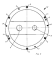
- the end shield 2 is in Fig. 2 shown.
- the bearing plate 2 is fastened with six screws 5 to the pump housing 2 (not shown).
- the screws 5 are designed as so-called high-strength screws with a strength class of 12.9.
- cylinder pins 7 are provided, which also absorb transverse forces in a crash.
- two heavy-duty pins 8 are provided, which serve to center the bearing plate and dampen load peaks with transverse forces.
- the bearing plate has two openings 9 for the passage of waves (not shown).
- cylindrical pins 7 and discs can be provided with a larger diameter than the diameter of the cylindrical pins.
- the diameter is smaller than the length of the cylindrical pins 7.
- the diameter is greater than the length of the discs.
- the rotor 27 and the rotor 28 are arranged in the rotor chamber 11, that is, in the suction chamber 11, the rotor 27 and the rotor 28 are arranged.
- the rotors 27, 28 are designed as double-bow rotors.
- the cross section of the rotors is formed perpendicular to an axis of the drive shaft 21 and the output shaft 22.
- the drive rotor 27 is driven by a motor (not shown).
- the output rotor 28 is via a transmission (not shown) synchronized with the drive rotor 27.
- the shape of the rotors 27, 28 has approximately the shape of the numeral "8".
- the drive rotor 27 has two arcuate portions 27a and two recessed portions 27b respectively formed between the two arcuate portions 27a.
- the output rotor 28 has two arcuate portions 28a and two recessed portions 28b respectively formed between the two arcuate portions 28a.
- the drive rotor 27 and the output rotor 28 are disposed in the rotor chamber 11 with a minimum distance between a peripheral surface 15a of the rotor chamber 11 and the rotors 27 and 28. That is, the peaks T of the arcuate portions 27a, 28a along the axes of Drive and output shafts 21, 22 extend and be prevented from coming into direct sliding contact with the inner surface 15a of the rotor chamber 11 or directly engage with it. Moreover, the drive rotor 27 and the output rotor 28, when engaged with each other, have a minimum clearance therebetween to prevent them from directly interfering with each other.
- a suction port 31a is provided in the peripheral wall 12a of the housing 12, so that a fluid can be sucked into the rotor chamber 11 (suction space) through the suction port 31a.
- an outlet port 32 a is provided so that the compressed fluid can escape from the rotor chamber 11.
- the drive rotor 27 and the output rotor 28 of the Wälzkolbenvakuumpumpe 10 are arranged so that according to the rotation of the drive rotor 27 and the output rotor 28, an arc portion 27 a of the output rotor 27 and a recessed portion 28 b of the output rotor 28 engage with each other and an arc portion 28 a of the output rotor 28 and a recessed portion 27b of the drive rotor 27 engage with each other.
Landscapes
- Engineering & Computer Science (AREA)
- Mechanical Engineering (AREA)
- General Engineering & Computer Science (AREA)
- Applications Or Details Of Rotary Compressors (AREA)
- Compressors, Vaccum Pumps And Other Relevant Systems (AREA)
Abstract
Description
- Die Erfindung betrifft eine Wälzkolbenvakuumpumpe mit einem Gehäuse mit einem Ansaugflansch und einem Ausstoßflansch.
- Aus der Praxis sind Wälzkolbenvakuumpumpen bekannt. In Wälzkolbenpumpen drehen sich zwei gegenläufig synchron laufende Rotoren berührungslos in einem Gehäuse. Die Rotoren können die Form einer "8" haben und sind voneinander und vom Stator durch einen engen Spalt getrennt. Das geförderte Gas wird von einer Ansaugöffnung zu einer Auslassöffnung transportiert.
- Eine Welle wird durch einen Motor angetrieben. Die Synchronisation der anderen Welle erfolgt über ein Zahnradpaar in einem Getrieberaum. Die Schmierung beschränkt sich auf den von einem Schöpfraum durch Dichtelemente abgetrennten Getrieberaum.
- Da im Schöpfraum keine Reibung auftritt, kann eine Wälzkolbenpumpe mit hoher Drehzahl bis zu 9.000 Umdrehungen pro Minute betrieben werden. Die symmetrische Massenverteilung der Rotoren um die Wellenachse erlaubt zudem eine einwandfreie dynamische Auswuchtung, so dass die Pumpe trotz hoher Drehzahl sehr ruhig läuft.
- Die Lager der Rotorwellen sind in zwei Seitenteilen, den Lagerschilden, des Gehäuses angeordnet. Auf der einen Seite sind die Lager vorteilhaft als Festlager, auf der anderen als Loslager ausgeführt, um die ungleichen Wärmedehnungen zwischen Gehäuse und Kolben zu ermöglichen. Die Schmierung der Lager und Zahnräder erfolgt üblicherweise mit Öl. Die Durchführung der Antriebswelle nach außen wird bei den Standardausführungen mit Sperröl überlagerten Radialwellendichtringen abgedichtet. Zum Schutz der Welle können die Dichtringe auf einer Schonbuchse, die bei Verschleiß ausgewechselt werden kann, laufen.
- Im kontinuierlichen Betrieb und für konstante Bedingungen stellt sich ein Gleichgewicht für eingebrachte Leistung und Abwärme ein. Die verschiedenen Komponenten der Wälzkolbenvakuumpumpe, deren Längenausdehnung von der Temperatur abhängt, weisen in diesem Zustand eine gleichbleibende Spaltgröße zwischen den Teilen auf. Die Spaltgröße zwischen pumpwirksamen Rotor und unbewegten Gehäusebauteilen sind dabei von besonderer Bedeutung für die Betriebssicherheit dieser Pumpe.
- In Ausnahmefällen können die Teile, beispielsweise in Folge von Verunreinigungen oder schnellen Temperaturänderungen, gegeneinander schlagen. Die dann entstehenden Kräfte müssen von den Gehäuse bildenden Komponenten und den dazugehörigen Befestigungselementen aufgenommen werden.
- Das der Erfindung zugrunde liegende technische Problem besteht darin, eine Wälzkolbenvakuumpumpe anzugeben, die ein Gehäuse aufweist, welches im Falle eines Crashs im Pumpeninneren gewährleistet, dass die Gehäusebauteile zusammenhalten.
- Dieses technische Problem wird durch eine Wälzkolbenvakuumpumpe mit den Merkmalen gemäß Anspruch 1 gelöst.
- Die erfindungsgemäße Wälzkolbenvakuumpumpe mit einem Gehäuse mit wenigstens zwei Gehäuseteilen, bei der die Gehäuseteile mittels einer Mehrzahl von Schrauben lösbar fest miteinander verbunden sind, zeichnet sich dadurch aus, dass wenigstens eine Schraube als Schraube mit einer Festigkeitsklasse von 8.8 oder höher ausgebildet ist.
- Die Festigkeitsklasse bei Schrauben besteht aus zwei Zahlen, die durch einen Punkt getrennt werden. Die Zahl links entspricht 1/100 der Nennzugfestigkeit Rm in MPa (Mega-Pascal).
- Die Zahl rechts vom Punkt gibt das Zehnfache des Verhältnisses zwischen Streckgrenze Re und Zugfestigkeit Rm (Streckgrenzenverhältnis) an. Daraus ergeben sich beispielsweise folgende Werte: 0,6/0,8/0,9. Diese Verhältniszahlen werden mit 10 multipliziert und ergeben dann den Wert nach dem Punkt.
- Zum Beispiel weist eine Schraube mit der Zugfestigkeit Rm = 1.000 MPa und einem Streckgrenzenverhältnis von 0,9 eine Festigkeitsklasse 10.9 auf.
- Die Ermittlung der Festigkeitsklasse erfolgt also folgendermaßen:
-

-

- Für eine Schraube mit der Festigkeitsklasse 10.9 gilt damit
- Zugfestigkeit Rm : 10 × 100 = 1.000 MPa
- Streckgrenze Re : (10 × 100) × (9 ÷ 10) = 1.000 × 0,9 = 900 MPa
- Schrauben mit einer Festigkeitsklasse von mehr als 8.8 werden auch als hochfeste Schrauben bezeichnet.
- Üblicherweise ist der Aufbau eines Gehäuses einer Wälzkolbenvakuumpumpe derart, dass an das Pumpengehäuse Lagerschilde und anschließend eine Kappe oder ein Deckel angeschraubt werden. Im Crashfall entstehen hohe Kräfte und Momente, die in verschiedene Richtungen wirken.
- Schrauben nehmen hierbei die axiale Belastung auf. Die Schrauben sind jedoch empfindlich gegenüber Abscherung. Die Gewindegänge wirken im Bereich oder Trennebenen wie Sollbruchstellen.
- Werden die Schrauben als hochfeste Schrauben gemäß der Erfindung ausgebildet mit einer Festigkeitsklasse von 8.8 oder höher, halten die Schrauben deutlich größeren Belastungen, beispielsweise Querkräften stand, so dass hierdurch das sogenannte Containment, das heißt, das Zusammenhalten der Gehäusebauteile besser gewährleistet wird.
- Vorteilhaft ist die wenigstens eine Schraube als Schraube mit einer Festigkeitsklasse von 10.9 oder höher ausgebildet. Hierdurch wird die erfindungsgemäße Aufgabe, das Containment, nämlich das Zusammenhalten der Gehäusebauteile zu gewährleisten, noch besser gelöst.
- Eine weitere vorteilhafte Ausführungsform der Erfindung sieht vor, dass die wenigstens zwei Gehäusebauteile mit den Schrauben mit einem Schraubenanzugsmoment von wenigstens 80 Nm (Newtonmeter) miteinander verbunden sind.
- Durch dieses erhöhte Schraubenanzugsmoment wird gewährleistet, dass eine hohe Reibung zwischen den Gehäusebauteilen vorhanden ist. Hierdurch wird die Energie aus Querbelastungen auf einen längeren Zeitraum gestreckt aufgezehrt. Lastspitzen werden "geglättet", so dass die Gefahr des Abscherens der Schrauben verringert wird.
- Eine weitere vorteilhafte Ausführungsform der Erfindung sieht vor, dass in Verbindungsebenen der wenigstens zwei Gehäuseteile wenigstens ein Zylinderstift vorgesehen ist.
- Zylinderstifte nehmen Querkräfte auf und verhindern somit das Abscheren der Schrauben. Dadurch dass die Zylinderstifte kein Gewinde aufweisen, sind bei den Zylinderstiften keine Sollbruchstellen vorhanden, so dass die Zylinderstifte große Querkräfte oder Scherkräfte aufnehmen können.
- Gemäß einer weiteren vorteilhaften Ausführungsform der Erfindung ist der wenigstens eine Zylinderstift als ein in Bohrungen benachbarter Gehäuseteile angeordneter Zylinderstift ausgebildet. Das bedeutet, dass zwei benachbarte Gehäuseteile Bohrungen aufweisen, die deckungsgleiche Öffnungen aufweisen. Die Gehäusebauteile weisen wenigstens ein Paar dieser miteinander korrespondierenden Bohrungen auf, so dass der Zylinderstift in diesem wenigstens einem Bohrungspaar angeordnet werden kann.
- Gemäß einer vorteilhaften Ausführungsform der Erfindung weist der Zylinderstift eine Festigkeitsklasse von gleich oder weniger als 8.8 auf. Das bedeutet, dass die Zylinderstifte vorteilhaft nicht hochfest sind, sondern eher zäh. Die Zylinderstifte sind demgemäß vorteilhaft nicht gehärtet ausgeführt. Hierdurch nehmen die Zylinderstifte die Querkräfte besser auf.
- Gemäß einer weiteren vorteilhaften Ausführungsform der Erfindung ist wenigstens eine Schraube durch einen Zylinderstift ersetzt, wobei maximal n-3 Schrauben durch Zylinderstifte ersetzt sind, wobei n die Anzahl der Schrauben zur Befestigung eines Gehäuseteiles an einem anderen Gehäuseteil ist.
- Das bedeutet, dass zur Befestigung des Gehäuseteiles mindestens drei Schrauben vorhanden sind. Die Schrauben werden benötigt, um die notwendige Vorspannung mit einem Anzugsmoment von beispielsweise wenigstens 80 Nm oder auch über 140 Nm zu erzielen, so dass bevorzugt ein Großteil der Anzahl der Schrauben verwendet wird. Dennoch ist es möglich, einen Teil der Schrauben durch Zylinderstifte zu ersetzen und somit Querkräfte durch die Zylinderstifte aufzunehmen.
- Vorteilhaft sind die Gehäuseteile der Wälzkolbenvakuumpumpe aus dem Pumpengehäuse und/oder wenigstens einem Lagerschild und/oder wenigstens einem Deckel gebildet.
- Das Pumpengehäuse nimmt die Kolben auf und bildet den sogenannten Schöpfraum.
- Das wenigstens eine Lagerschild trägt die Lager, mit denen die Welle, die wiederum die Kolben trägt, drehbar gelagert ist. Der wenigstens eine Deckel schließt das Pumpengehäuse lagerschildseitig vakuumdicht und/oder fluiddicht ab.
- Das Pumpengehäuse kann gemäß einer vorteilhaften Ausführungsform ein- oder mehrteilig ausgebildet sein. Das Vorteilhaft ist der Teil des Pumpengehäuses, welcher die Wälzkolben aufnimmt, ein- oder mehrteilig ausgebildet. Ist das Pumpengehäuse mehrteilig ausgebildet, werden diese Teile des Pumpengehäuses vorteilhaft ebenfalls mit Schrauben mit einer Festigkeitsklasse von 8.8 oder höher miteinander verbunden. Zusätzlich kann die Anordnung von Zylinderstiften vorgesehen sein.
- Eine weitere vorteilhafte Ausführungsform der Erfindung sieht vor, dass die Schrauben in einer Schraubenbuchse angeordnet sind und dass die Schraubenbuchse in einer Bohrung eines Gehäuseteiles oder in zwei gegenüberliegenden Bohrungen von zwei zu verbindenden Gehäuseteilen angeordnet ist. Durch die Ausführungsform mit einer Schraubenbuchse können diese Buchsen zusätzlich Scherkräfte aufnehmen, wodurch das Zusammenhalten der Gehäuseteile im Crashfall noch besser gewährleistet ist.
- Es besteht auch die Möglichkeit, Durchgangsbohrungen zur Aufnahme der Schrauben aufzuweiten oder anzupassen, das heißt, diese können konisch oder abgestuft ausgebildet sein. Hierdurch werden mehr Querbewegungen ohne ein Abscheren der Schrauben ermöglicht, wobei die axiale Vorspannung erhalten bleibt.
- Gemäß einer weiteren vorteilhaften Ausführungsform der Erfindung sind die Passungen der Zylinderstifte in den Bohrungen kleiner als das Spiel zwischen der wenigstens einen Schraube und der die Schraube aufnehmenden Bohrungen. Auch hierdurch ist gewährleistet, dass im Crashfall als erstes die Zylinderstifte die Querkräfte aufnehmen. Nach einem Verformen oder teilweisen Verformen dieser Zylinderstifte greifen die Querkräfte an den Schrauben an.
- Eine weitere vorteilhafte Ausführungsform der Erfindung sieht vor, dass für die Anordnung jedes Lagerschildes und/oder jeden Deckels zwei Schwerspannstifte vorgesehen sind. Die Schwerspannstifte dienen der Ausrichtung des Lagerschildes zum Gehäuse. Üblicherweise erfolgt nach der Ausrichtung des Lagerschildes die Fixierung mit Schrauben. Diese Schwerspannstifte nehmen zusätzlich Querkräfte auf.
- Gemäß einer bevorzugten Ausführungsform der Erfindung ist vorgesehen, dass das Spiel von den Schrauben zu den Zylinderstiften zu den Schwerspannstiften in ihren jeweiligen Bohrungen abnehmend ausgebildet ist. Hierdurch wird gewährleistet, dass als erstes die Schwerspannstifte Querkräfte aufnehmen. Als nächstes greifen die Querkräfte an den Zylinderstiften an und als letztes greifen die Querkräfte an den Schrauben an.
- Durch diese Ausführungsform wird die Belastungsspitze (Peak) der auftretenden Kräfte im Falle eines Crashs gestreckt, so dass ein Zusammenhalten der Gehäusebauteile gewährleistet ist.
- Der Aufbau des Gehäuses der Wälzkolbenvakuumpumpe ist vorteilhaft derart, dass das wenigstens eine Lagerschild mit dem Pumpengehäuse verschraubt ausgebildet ist. Vorzugsweise ist ein Deckel gegen das Lagerschild verschraubt ausgebildet. Hierdurch wird ein vakuumdichter oder fluiddichter Abschluss gebildet. Diese Gehäuseteile sind gemäß der Erfindung mit wenigstens einer Schraube miteinander verbunden, die eine Festigkeitsklasse von 8.8 oder höher aufweist. Grundsätzlich ist es möglich, dass Schrauben mit unterschiedlichen Festigkeitsklassen zum Verbinden der Gehäuseteile vorgesehen sind, das bedeutet, dass wenigstens eine Schraube mit einer Festigkeitsklasse von 8.8 oder höher ausgebildet ist, dass weitere Schrauben jedoch mit einer niedrigeren Festigkeitsklasse ausgebildet sein können.
- Die Erfindung geht davon aus, dass es vorteilhaft ist, die Bewegungsenergie aufzuzehren und Belastungsspitzen über einen verlängerten Zeitraum abzufedern.
- Im Crashfall treten üblicherweise plastische Verformungen von Lagerschild und Deckel und/oder Kappe auf.
- Grundsätzlich besteht auch die Möglichkeit, einen Spezialguss zu verwenden, der höheren Kräften standhält. Es besteht auch die Möglichkeit, die Gehäuseteile verzahnend ineinandergreifen zu lassen, um durch diese Ausbildung auftretende Querkräfte aufzunehmen.
- Es besteht auch die Möglichkeit, anstelle von Schrauben und/oder Zylinderstiften oder zusätzlich zu Schrauben und/oder Zylinderstiften scheibenförmige Bauteile zwischen den Gehäuseteilen anzuordnen. Die scheibenförmigen Bauteile weise größere Durchmesser als die Zylinderstifte auf und können deshalb größere Querkräfte aufnehmen.
- Weitere Merkmale und Vorteile der Erfindung ergeben sich anhand der zugehörigen Zeichnung, in der ein Ausführungsbeispiel einer erfindungsgemäßen Vakuumpumpe nur beispielhaft dargestellt ist. In der Zeichnung zeigen:
- Fig. 1
- ein Gehäuse einer Wälzkolbenvakuumpumpe in perspektivischer Ansicht;
- Fig. 2
- ein Lagerschild in Draufsicht;
- Fig. 3
- einen Querschnitt eines zweibogigen antreibenden und eines zweibogigen angetriebenen Rotors einer zum Stand der Technik gehörenden Wälzkolbenvakuumpumpe.
-
Fig. 1 zeigt eine Wälzkolbenvakuumpumpe 1 mit einem ersten Gehäusebauteil 2, dem eigentlichen Pumpengehäuse, welches Kolben (nicht dargestellt) der Wälzkolbenvakuumpumpe 1 aufnimmt. - Die Wälzkolbenvakuumpumpe 1 weist darüber hinaus als weiteres Gehäuseteil ein Lagerschild 3 auf sowie einen Deckel 4. Das Lagerschild 3 ist mit Schrauben 5 an dem Pumpengehäuse 2 befestigt. Der Deckel 4 ist mit Schrauben 6 an dem Lagerschild 3 angeordnet.
- Das Gehäuse der Wälzkolbenvakuumpumpe 1 weist einen Ansaugflansch 33 und einen Ausstoßflansch 34 auf. Der Ausstoßflansch 34 ist mit Schrauben 35 an dem Gehäuse befestigt.
- Das Lagerschild 2 ist in
Fig. 2 dargestellt. Das Lagerschild 2 ist mit sechs Schrauben 5 an dem Pumpengehäuse 2 (nicht dargestellt) befestigt. Die Schrauben 5 sind als sogenannte hochfeste Schrauben mit einer Festigkeitsklasse von 12.9 ausgebildet. - Darüber hinaus sind vier Zylinderstifte 7 vorgesehen, die in einem Crashfall ebenfalls Querkräfte aufnehmen. Weiterhin sind zwei Schwerspannstifte 8 vorgesehen, die der Zentrierung des Lagerschildes dienen und Belastungsspitzen bei Querkräften dämpfen.
- Das Lagerschild weist zwei Öffnungen 9 für die Durchführung von Wellen (nicht dargestellt) auf.
- Anstelle der Zylinderstifte 7 können auch Scheiben mit einem größeren Durchmesser als der Durchmesser der Zylinderstifte vorgesehen sein. Bei den Zylinderstiften 7 ist der Durchmesser kleiner als die Länge der Zylinderstifte 7. Bei den Scheiben ist der Durchmesser größer als die Länge der Scheiben.
- Wie in
Fig. 3 dargestellt, sind in der Rotorkammer 11, das heißt in dem Schöpfraum 11 der Rotor 27 und der Rotor 28 angeordnet. Die Rotoren 27, 28 sind als zweibogige Rotoren ausgebildet. Der Querschnitt der Rotoren ist senkrecht zu einer Achse der Antriebswelle 21 und der Abtriebswelle 22 ausgebildet. Der Antriebsrotor 27 wird von einem Motor (nicht dargestellt) angetrieben. Der Abtriebsrotor 28 ist über ein Getriebe (nicht dargestellt) mit dem Antriebsrotor 27 synchronisiert. - Die Form der Rotoren 27, 28 hat annähernd die Form der Ziffer "8". Der Antriebsrotor 27 hat zwei Bogenabschnitte 27a und zwei ausgesparte Abschnitte 27b, die jeweils zwischen den beiden Bogenabschnitten 27a ausgebildet sind. In gleicher Weise hat der Abtriebsrotor 28 zwei Bogenabschnitte 28a und zwei ausgesparte Abschnitte 28b, die jeweils zwischen den zwei Bogenabschnitten 28a ausgebildet sind.
- Der Antriebsrotor 27 und der Abtriebsrotor 28 sind in der Rotorkammer 11 angeordnet mit einem minimalen Abstand zwischen einer Umfangsfläche 15a der Rotorkammer 11 und der Rotoren 27 und 28. Das bedeutet, dass sich die Spitzen beziehungsweise Scheitel T der Bogenabschnitte 27a, 28a entlang den Achsen der Antriebs- und Abtriebswelle 21, 22 erstrecken und davon abgehalten werden, dass sie in direktem Gleitkontakt mit der Innenfläche 15a der Rotorkammer 11 kommen oder direkt mit ihr eingreifen. Darüber hinaus haben der Antriebsrotor 27 und der Abtriebsrotor 28, wenn sie miteinander eingreifen, einen minimalen Abstand zwischen sich ausgebildet, um zu verhindern, dass sie direkt miteinander eingreifen, beziehungsweise sich behindern. In der Umfangswand 12a des Gehäuses 12 ist eine Ansaugöffnung 31a vorgesehen, damit ein Fluid durch die Ansaugöffnung 31a in die Rotorkammer 11 (Schöpfraum) angesaugt werden kann. Darüber hinaus ist ein Auslassanschluss 32a vorgesehen, damit das komprimierte Fluid aus der Rotorkammer 11 austreten kann. Bei dem Betrieb der Wälzkolbenvakuumpumpe 10 wird die Antriebswelle 21 durch einen Elektromotor (nicht dargestellt) gedreht. Hierdurch wird die Abtriebswelle 22 in Gegenrichtung zu der Antriebswelle 21 durch die Eingreifbeziehung zwischen einem Antriebszahnrad und einem Abtriebszahnrand gedreht und der Antriebsrotor 27 und der Abtriebsrotor 28 werden demzufolge gedreht.
- Der Antriebsrotor 27 und der Abtriebsrotor 28 der Wälzkolbenvakuumpumpe 10 sind so angeordnet, dass gemäß der Rotation des Antriebsrotors 27 und des Abtriebsrotors 28 ein Bogenabschnitt 27a des Abtriebsrotors 27 und ein ausgesparter Abschnitt 28b des Abtriebsrotors 28 miteinander eingreifen und ein Bogenabschnitt 28a des Abtriebsrotors 28 und ein ausgesparter Abschnitt 27b des Antriebsrotors 27 miteinander eingreifen.
- Durch Drehung des Antriebsrotors 27 und des Abtriebsrotors 28 wird ein Fluid in die Rotorkammer 11 durch den Ansauganschluss 31a hindurch angesaugt und das Fluid wird in dem Raum S gefangen, der zwischen der Außenumfangsfläche des Abtriebsrotors 28 und der Umfangsfläche 15a des Gehäuses 15 der Rotorkammer 11 definiert ist, in der in
Fig. 3 dargestellten Stellung der Rotoren 27, 28. Anschließend wird das Fluid in dem Raum S gemäß der Drehung des Antriebsrotors 27 und des Abtriebsrotors 28 zu dem Auslassanschluss 32a hin weitergeleitet und wird dann aus der Rotorkammer 11 durch den Auslassanschluss 32a hindurch ausgestoßen. -
- 1
- Wälzkolbenvakuumpumpe
- 2
- Pumpengehäuse
- 3
- Lagerschild
- 4
- Deckel
- 5
- Schrauben
- 6
- Schrauben
- 7
- Zylinderstifte
- 8
- Schwerspannstifte
- 9
- Bohrungen
- 10
- Wälzkolbenvakuumpumpe
- 11
- Rotorkammer (Schöpfraum)
- 12
- Rotorgehäuse
- 12a
- zylindrische Umfangswand
- 15
- Gehäuse
- 15a
- Umfangsfläche der Rotorkammer 15
- 21
- Antriebswelle
- 22
- Abtriebswelle
- 27
- Antriebsrotor
- 27a
- Bogenabschnitte
- 27b
- Taillen
- 28
- Abtriebsrotor
- 28a
- Bogenabschnitte
- 28b
- Taillen
- 31a
- Ansauganschluss
- 32a
- Auslassanschluss
- 33
- Ansaugflansch
- 34
- Ausstoßflansch
- 35
- Schrauben
- S
- Raum (Teil des Schöpfraumes)
- T
- Scheitel
Claims (15)
- Wälzkolbenvakuumpumpe mit einem Gehäuse mit wenigstens zwei Gehäuseteilen, bei der die Gehäuseteile mittels einer Mehrzahl von Schrauben lösbar fest miteinander verbunden sind,
dadurch gekennzeichnet, dass wenigstens eine Schraube (5, 6) als Schraube mit einer Festigkeitsklasse von 8.8 oder höher ausgebildet ist. - Wälzkolbenvakuumpumpe nach Anspruch 1, dadurch gekennzeichnet, dass wenigstens eine Schraube (5, 6) als Schraube mit einer Festigkeitsklasse von 10.9 oder höher ausgebildet ist.
- Wälzkolbenvakuumpumpe nach Anspruch 1 oder 2, dadurch gekennzeichnet, dass die wenigstens zwei Gehäusebauteile (2, 3, 4) mit den Schrauben (5, 6) mit einem Schraubenanzugsmoment von wenigstens 80 Nm (Newtonmeter) miteinander verbunden sind.
- Wälzkolbenvakuumpumpe nach einem der vorhergehenden Ansprüche, dadurch gekennzeichnet, dass in den Verbindungsebenen der wenigstens zwei Gehäuseteile (2, 3, 4) wenigstens ein Zylinderstift (7) vorgesehen ist.
- Wälzkolbenvakuumpumpe nach Anspruch 4, dadurch gekennzeichnet, dass der wenigstens eine Zylinderstift (7) als ein in Bohrungen benachbarter Gehäuseteile (2, 3, 4) angeordneter Zylinderstift (7) ausgebildet ist.
- Wälzkolbenvakuumpumpe nach Anspruch 4 oder 5, dadurch gekennzeichnet, dass der wenigstens eine Zylinderstift (7) mit einer Festigkeitsklasse von gleich oder weniger 8.8 ausgebildet ist.
- Wälzkolbenvakuumpumpe nach einem der vorhergehenden Ansprüche, dadurch gekennzeichnet, dass wenigstens eine Schraube (5, 6) durch einen Zylinderstift (7) ersetzt ist, und dass maximal n-3 Schrauben (5, 6) durch Zylinderstifte (7) ersetzt sind, wobei n die Anzahl der Schrauben (5, 6) zur Befestigung eines Gehäuseteiles (2, 3) an einem anderen Gehäuseteil (3, 4) ist.
- Wälzkolbenvakuumpumpe nach einem der vorhergehenden Ansprüche, dadurch gekennzeichnet, dass die Gehäuseteile (2, 3, 4) aus dem Pumpengehäuse (2) und/oder wenigstens einem Lagerschild (3) und/oder wenigstens einem Deckel (4) gebildet sind.
- Wälzkolbenvakuumpumpe nach einem der vorhergehenden Ansprüche, dadurch gekennzeichnet, dass die Schrauben (5, 6) in einer Schraubenbuchse angeordnet sind, und dass die Schraubenbuchse in einer Bohrung eines Gehäuseteiles (2, 3, 4) oder in zwei gegenüberliegenden Bohrungen von zwei zu verbindenden Gehäuseteilen (2, 3, 4) angeordnet ist.
- Wälzkolbenvakuumpumpe nach einem der vorhergehenden Ansprüche, dadurch gekennzeichnet, dass Bohrungen zur Aufnahme von Schrauben (5, 6) konisch oder abgestuft ausgebildet sind.
- Wälzkolbenvakuumpumpe nach einem der vorhergehenden Ansprüche, dadurch gekennzeichnet, dass die Passungen der Zylinderstifte (7) in den Bohrungen kleiner sind als das Spiel zwischen der wenigstens einen Schraube (5, 6) und der die Schraube (5, 6) aufnehmenden Bohrung.
- Wälzkolbenvakuumpumpe nach einem der vorhergehenden Ansprüche, dadurch gekennzeichnet, dass für die Anordnung jedes Lagerschildes (3) und/oder jedes Deckels (4) zwei Schwerspannstifte (8) vorgesehen sind.
- Wälzkolbenvakuumpumpe nach einem der vorhergehenden Ansprüche, dadurch gekennzeichnet, dass das Spiel von den Schrauben (5, 6) zu den Zylinderstiften (7) zu den Schwerspannstiften (8) in ihren jeweiligen Bohrungen abnehmend ausgebildet ist.
- Wälzkolbenvakuumpumpe nach einem der vorhergehenden Ansprüche, dadurch gekennzeichnet, dass Schrauben (5, 6) mit unterschiedlichen Festigkeitsklassen zum Verbinden von zwei Gehäuseteilen (2, 3, 4) vorgesehen sind.
- Wälzkolbenvakuumpumpe nach einem der vorhergehenden Ansprüche, dadurch gekennzeichnet, dass zusätzlich zu den Schrauben (5, 6) mit einer Festigkeitsklasse von 8.8 oder höher Schrauben mit einer Festigkeitsklasse von weniger als 8.8 vorgesehen sind.
Applications Claiming Priority (1)
| Application Number | Priority Date | Filing Date | Title |
|---|---|---|---|
| DE102014104161.5A DE102014104161B4 (de) | 2014-03-26 | 2014-03-26 | Wälzkolbenvakuumpumpe |
Publications (3)
| Publication Number | Publication Date |
|---|---|
| EP2924293A2 true EP2924293A2 (de) | 2015-09-30 |
| EP2924293A3 EP2924293A3 (de) | 2015-11-11 |
| EP2924293B1 EP2924293B1 (de) | 2019-04-17 |
Family
ID=52391853
Family Applications (1)
| Application Number | Title | Priority Date | Filing Date |
|---|---|---|---|
| EP15152271.1A Active EP2924293B1 (de) | 2014-03-26 | 2015-01-23 | Wälzkolbenvakuumpumpe |
Country Status (2)
| Country | Link |
|---|---|
| EP (1) | EP2924293B1 (de) |
| DE (1) | DE102014104161B4 (de) |
Family Cites Families (19)
| Publication number | Priority date | Publication date | Assignee | Title |
|---|---|---|---|---|
| DE541946C (de) * | 1931-04-26 | 1932-01-16 | Argus Motoren Ges M B H | Verbindung zwischen Laeufer und Welle bei Roots-Geblaesen |
| GB522473A (en) | 1938-10-12 | 1940-06-19 | Frank Christian Fulcher | Ported end sealing plates for rotary pumps |
| DE7731431U1 (de) * | 1977-10-11 | 1978-09-21 | Aerzener Maschinenfabrik Gmbh, 3251 Aerzen | Anlaufsicherung fuer sich relativ zueinander bewegende maschinenteile |
| JP3426734B2 (ja) * | 1994-10-17 | 2003-07-14 | 三菱重工業株式会社 | ターボ分子ポンプ |
| JPH10266982A (ja) * | 1997-03-21 | 1998-10-06 | Tochigi Fuji Ind Co Ltd | ルーツ式流体機械 |
| US6138646A (en) * | 1997-07-18 | 2000-10-31 | Hansen; Craig N. | Rotary fluid mover |
| US6485254B1 (en) * | 2000-10-19 | 2002-11-26 | Applied Materials, Inc. | Energy dissipating coupling |
| JP4126212B2 (ja) * | 2001-11-19 | 2008-07-30 | エドワーズ株式会社 | 真空ポンプ |
| DE10342907A1 (de) * | 2003-09-17 | 2005-04-21 | Pfeiffer Vacuum Gmbh | Vakuumpumpe mit schnelldrehendem Rotor |
| WO2005105325A1 (en) * | 2004-04-23 | 2005-11-10 | Thomas Industries, Inc. | Coated pump assembly |
| JP2006063969A (ja) * | 2004-07-30 | 2006-03-09 | Shimadzu Corp | 回転式真空ポンプ、真空装置およびポンプ接続構造 |
| JP2008038726A (ja) * | 2006-08-04 | 2008-02-21 | Toyota Industries Corp | ポンプ |
| GB0620144D0 (en) * | 2006-10-11 | 2006-11-22 | Boc Group Plc | Vacuum pump |
| RS51355B (sr) * | 2008-04-01 | 2011-02-28 | Zivoslav Milovanovic | Uređaj sa rotacionim klipovima koji se može koristiti kao kompresor, pumpa, vakuum pumpa, turbina, motor i kao druge pogonske i gonjene hidraulične-pneumatske mašine |
| DE102008035972A1 (de) * | 2008-07-31 | 2010-02-04 | Pfeiffer Vacuum Gmbh | Vakuumpumpanordnung |
| DE102008060540A1 (de) * | 2008-12-04 | 2010-06-10 | Pfeiffer Vacuum Gmbh | Wälzkolbenvakuumpumpe |
| DE102010012759B4 (de) * | 2010-03-25 | 2018-06-21 | Pfeiffer Vacuum Gmbh | Rotor für eine Vakuumpumpe |
| JP5626445B2 (ja) * | 2011-02-22 | 2014-11-19 | 株式会社島津製作所 | ターボ分子ポンプのボルト締結構造およびターボ分子ポンプ |
| EP2642127B1 (de) | 2011-06-06 | 2019-01-09 | Vacuubrand Gmbh + Co Kg | Vakuumpumpe mit einseitiger Lagerung der Pumpenrotoren |
-
2014
- 2014-03-26 DE DE102014104161.5A patent/DE102014104161B4/de active Active
-
2015
- 2015-01-23 EP EP15152271.1A patent/EP2924293B1/de active Active
Non-Patent Citations (1)
| Title |
|---|
| None |
Also Published As
| Publication number | Publication date |
|---|---|
| EP2924293A3 (de) | 2015-11-11 |
| EP2924293B1 (de) | 2019-04-17 |
| DE102014104161B4 (de) | 2025-09-18 |
| DE102014104161A1 (de) | 2015-10-01 |
Similar Documents
| Publication | Publication Date | Title |
|---|---|---|
| EP3489550B1 (de) | Planetengetriebe und gleitlagerstift für ein planetengetriebe | |
| EP3489548B1 (de) | Planetengetriebe | |
| DE2801206A1 (de) | Spiralartige einrichtung mit einem festen gekroepften kurbelantriebsmechanismus | |
| DE3413725C2 (de) | Anordnung zur Begrenzung von Schublasten bei Dampfturbinenwellen | |
| DE69521950T2 (de) | Innenzahnradanlage | |
| DE19513380C2 (de) | Abdichtung, Lagerung und Antrieb der Rotoren eines trockenlaufenden Schraubenrotorverdichters | |
| DE212012000091U1 (de) | Pumpenrotor | |
| DE3722164C2 (de) | Turbomolekularpumpe | |
| DE69819293T2 (de) | Hydraulikdichtung | |
| EP0614012A1 (de) | Verdrängermaschine nach dem Spiralprinzip | |
| DE102017106760B4 (de) | Drehzahlerhöher | |
| EP2707629B1 (de) | Vorrichtung zum abdichten eines pumpraums einer drehkolbenpumpe, sowie drehkolbenpumpe mit selbiger | |
| EP3827170B1 (de) | Fluidfördereinrichtung | |
| EP2924293B1 (de) | Wälzkolbenvakuumpumpe | |
| DE102011003177A1 (de) | Antrieb für einen Spindel-Kompressor | |
| EP2556256B1 (de) | Drehkolbenpumpe und verfahren zum betreiben einer drehkolbenpumpe | |
| EP0942172B1 (de) | Mehrwellenvakuumpumpe | |
| EP3441613B1 (de) | Hydrostatische zahnrad-kreiskolbenmaschine | |
| DE3709106A1 (de) | Kaeltekompressor-brennkraftmaschinenaggregat der rotationskolbenbauweise | |
| EP4386177A1 (de) | Zahnradpumpe | |
| DE112006000321T5 (de) | Dichtungsstruktur einer Turbomolekularpumpe | |
| DE102007030201A1 (de) | Antrieb für einen Schraubenspindelrotor | |
| EP2690252A1 (de) | Trochoiden-Innenzahnradmaschine | |
| EP0381682A1 (de) | Drehkolbenverdichter. | |
| DE3307790A1 (de) | Aggregat aus zwei zahnringpumpen |
Legal Events
| Date | Code | Title | Description |
|---|---|---|---|
| PUAI | Public reference made under article 153(3) epc to a published international application that has entered the european phase |
Free format text: ORIGINAL CODE: 0009012 |
|
| AK | Designated contracting states |
Kind code of ref document: A2 Designated state(s): AL AT BE BG CH CY CZ DE DK EE ES FI FR GB GR HR HU IE IS IT LI LT LU LV MC MK MT NL NO PL PT RO RS SE SI SK SM TR |
|
| AX | Request for extension of the european patent |
Extension state: BA ME |
|
| PUAL | Search report despatched |
Free format text: ORIGINAL CODE: 0009013 |
|
| RIC1 | Information provided on ipc code assigned before grant |
Ipc: F04C 18/12 20060101ALI20150914BHEP Ipc: F04C 29/04 20060101AFI20150914BHEP |
|
| AK | Designated contracting states |
Kind code of ref document: A3 Designated state(s): AL AT BE BG CH CY CZ DE DK EE ES FI FR GB GR HR HU IE IS IT LI LT LU LV MC MK MT NL NO PL PT RO RS SE SI SK SM TR |
|
| AX | Request for extension of the european patent |
Extension state: BA ME |
|
| 17P | Request for examination filed |
Effective date: 20160414 |
|
| RBV | Designated contracting states (corrected) |
Designated state(s): AL AT BE BG CH CY CZ DE DK EE ES FI FR GB GR HR HU IE IS IT LI LT LU LV MC MK MT NL NO PL PT RO RS SE SI SK SM TR |
|
| GRAP | Despatch of communication of intention to grant a patent |
Free format text: ORIGINAL CODE: EPIDOSNIGR1 |
|
| STAA | Information on the status of an ep patent application or granted ep patent |
Free format text: STATUS: GRANT OF PATENT IS INTENDED |
|
| INTG | Intention to grant announced |
Effective date: 20181116 |
|
| GRAS | Grant fee paid |
Free format text: ORIGINAL CODE: EPIDOSNIGR3 |
|
| GRAA | (expected) grant |
Free format text: ORIGINAL CODE: 0009210 |
|
| STAA | Information on the status of an ep patent application or granted ep patent |
Free format text: STATUS: THE PATENT HAS BEEN GRANTED |
|
| AK | Designated contracting states |
Kind code of ref document: B1 Designated state(s): AL AT BE BG CH CY CZ DE DK EE ES FI FR GB GR HR HU IE IS IT LI LT LU LV MC MK MT NL NO PL PT RO RS SE SI SK SM TR |
|
| REG | Reference to a national code |
Ref country code: GB Ref legal event code: FG4D Free format text: NOT ENGLISH |
|
| REG | Reference to a national code |
Ref country code: CH Ref legal event code: EP |
|
| REG | Reference to a national code |
Ref country code: DE Ref legal event code: R096 Ref document number: 502015008695 Country of ref document: DE |
|
| REG | Reference to a national code |
Ref country code: AT Ref legal event code: REF Ref document number: 1121849 Country of ref document: AT Kind code of ref document: T Effective date: 20190515 Ref country code: IE Ref legal event code: FG4D Free format text: LANGUAGE OF EP DOCUMENT: GERMAN |
|
| REG | Reference to a national code |
Ref country code: NL Ref legal event code: MP Effective date: 20190417 |
|
| REG | Reference to a national code |
Ref country code: LT Ref legal event code: MG4D |
|
| PG25 | Lapsed in a contracting state [announced via postgrant information from national office to epo] |
Ref country code: NL Free format text: LAPSE BECAUSE OF FAILURE TO SUBMIT A TRANSLATION OF THE DESCRIPTION OR TO PAY THE FEE WITHIN THE PRESCRIBED TIME-LIMIT Effective date: 20190417 |
|
| PG25 | Lapsed in a contracting state [announced via postgrant information from national office to epo] |
Ref country code: NO Free format text: LAPSE BECAUSE OF FAILURE TO SUBMIT A TRANSLATION OF THE DESCRIPTION OR TO PAY THE FEE WITHIN THE PRESCRIBED TIME-LIMIT Effective date: 20190717 Ref country code: AL Free format text: LAPSE BECAUSE OF FAILURE TO SUBMIT A TRANSLATION OF THE DESCRIPTION OR TO PAY THE FEE WITHIN THE PRESCRIBED TIME-LIMIT Effective date: 20190417 Ref country code: FI Free format text: LAPSE BECAUSE OF FAILURE TO SUBMIT A TRANSLATION OF THE DESCRIPTION OR TO PAY THE FEE WITHIN THE PRESCRIBED TIME-LIMIT Effective date: 20190417 Ref country code: SE Free format text: LAPSE BECAUSE OF FAILURE TO SUBMIT A TRANSLATION OF THE DESCRIPTION OR TO PAY THE FEE WITHIN THE PRESCRIBED TIME-LIMIT Effective date: 20190417 Ref country code: PT Free format text: LAPSE BECAUSE OF FAILURE TO SUBMIT A TRANSLATION OF THE DESCRIPTION OR TO PAY THE FEE WITHIN THE PRESCRIBED TIME-LIMIT Effective date: 20190817 Ref country code: HR Free format text: LAPSE BECAUSE OF FAILURE TO SUBMIT A TRANSLATION OF THE DESCRIPTION OR TO PAY THE FEE WITHIN THE PRESCRIBED TIME-LIMIT Effective date: 20190417 Ref country code: LT Free format text: LAPSE BECAUSE OF FAILURE TO SUBMIT A TRANSLATION OF THE DESCRIPTION OR TO PAY THE FEE WITHIN THE PRESCRIBED TIME-LIMIT Effective date: 20190417 Ref country code: ES Free format text: LAPSE BECAUSE OF FAILURE TO SUBMIT A TRANSLATION OF THE DESCRIPTION OR TO PAY THE FEE WITHIN THE PRESCRIBED TIME-LIMIT Effective date: 20190417 |
|
| PG25 | Lapsed in a contracting state [announced via postgrant information from national office to epo] |
Ref country code: GR Free format text: LAPSE BECAUSE OF FAILURE TO SUBMIT A TRANSLATION OF THE DESCRIPTION OR TO PAY THE FEE WITHIN THE PRESCRIBED TIME-LIMIT Effective date: 20190718 Ref country code: PL Free format text: LAPSE BECAUSE OF FAILURE TO SUBMIT A TRANSLATION OF THE DESCRIPTION OR TO PAY THE FEE WITHIN THE PRESCRIBED TIME-LIMIT Effective date: 20190417 Ref country code: BG Free format text: LAPSE BECAUSE OF FAILURE TO SUBMIT A TRANSLATION OF THE DESCRIPTION OR TO PAY THE FEE WITHIN THE PRESCRIBED TIME-LIMIT Effective date: 20190717 Ref country code: RS Free format text: LAPSE BECAUSE OF FAILURE TO SUBMIT A TRANSLATION OF THE DESCRIPTION OR TO PAY THE FEE WITHIN THE PRESCRIBED TIME-LIMIT Effective date: 20190417 Ref country code: LV Free format text: LAPSE BECAUSE OF FAILURE TO SUBMIT A TRANSLATION OF THE DESCRIPTION OR TO PAY THE FEE WITHIN THE PRESCRIBED TIME-LIMIT Effective date: 20190417 |
|
| PG25 | Lapsed in a contracting state [announced via postgrant information from national office to epo] |
Ref country code: IS Free format text: LAPSE BECAUSE OF FAILURE TO SUBMIT A TRANSLATION OF THE DESCRIPTION OR TO PAY THE FEE WITHIN THE PRESCRIBED TIME-LIMIT Effective date: 20190817 |
|
| REG | Reference to a national code |
Ref country code: DE Ref legal event code: R026 Ref document number: 502015008695 Country of ref document: DE |
|
| PLBI | Opposition filed |
Free format text: ORIGINAL CODE: 0009260 |
|
| PG25 | Lapsed in a contracting state [announced via postgrant information from national office to epo] |
Ref country code: RO Free format text: LAPSE BECAUSE OF FAILURE TO SUBMIT A TRANSLATION OF THE DESCRIPTION OR TO PAY THE FEE WITHIN THE PRESCRIBED TIME-LIMIT Effective date: 20190417 Ref country code: EE Free format text: LAPSE BECAUSE OF FAILURE TO SUBMIT A TRANSLATION OF THE DESCRIPTION OR TO PAY THE FEE WITHIN THE PRESCRIBED TIME-LIMIT Effective date: 20190417 Ref country code: DK Free format text: LAPSE BECAUSE OF FAILURE TO SUBMIT A TRANSLATION OF THE DESCRIPTION OR TO PAY THE FEE WITHIN THE PRESCRIBED TIME-LIMIT Effective date: 20190417 Ref country code: SK Free format text: LAPSE BECAUSE OF FAILURE TO SUBMIT A TRANSLATION OF THE DESCRIPTION OR TO PAY THE FEE WITHIN THE PRESCRIBED TIME-LIMIT Effective date: 20190417 |
|
| PLAX | Notice of opposition and request to file observation + time limit sent |
Free format text: ORIGINAL CODE: EPIDOSNOBS2 |
|
| 26 | Opposition filed |
Opponent name: EDWARDS LIMITED Effective date: 20200117 |
|
| PG25 | Lapsed in a contracting state [announced via postgrant information from national office to epo] |
Ref country code: SM Free format text: LAPSE BECAUSE OF FAILURE TO SUBMIT A TRANSLATION OF THE DESCRIPTION OR TO PAY THE FEE WITHIN THE PRESCRIBED TIME-LIMIT Effective date: 20190417 |
|
| PG25 | Lapsed in a contracting state [announced via postgrant information from national office to epo] |
Ref country code: TR Free format text: LAPSE BECAUSE OF FAILURE TO SUBMIT A TRANSLATION OF THE DESCRIPTION OR TO PAY THE FEE WITHIN THE PRESCRIBED TIME-LIMIT Effective date: 20190417 |
|
| PLBB | Reply of patent proprietor to notice(s) of opposition received |
Free format text: ORIGINAL CODE: EPIDOSNOBS3 |
|
| PG25 | Lapsed in a contracting state [announced via postgrant information from national office to epo] |
Ref country code: SI Free format text: LAPSE BECAUSE OF FAILURE TO SUBMIT A TRANSLATION OF THE DESCRIPTION OR TO PAY THE FEE WITHIN THE PRESCRIBED TIME-LIMIT Effective date: 20190417 |
|
| PG25 | Lapsed in a contracting state [announced via postgrant information from national office to epo] |
Ref country code: MC Free format text: LAPSE BECAUSE OF FAILURE TO SUBMIT A TRANSLATION OF THE DESCRIPTION OR TO PAY THE FEE WITHIN THE PRESCRIBED TIME-LIMIT Effective date: 20190417 |
|
| REG | Reference to a national code |
Ref country code: CH Ref legal event code: PL |
|
| REG | Reference to a national code |
Ref country code: BE Ref legal event code: MM Effective date: 20200131 |
|
| PG25 | Lapsed in a contracting state [announced via postgrant information from national office to epo] |
Ref country code: LU Free format text: LAPSE BECAUSE OF NON-PAYMENT OF DUE FEES Effective date: 20200123 |
|
| PG25 | Lapsed in a contracting state [announced via postgrant information from national office to epo] |
Ref country code: BE Free format text: LAPSE BECAUSE OF NON-PAYMENT OF DUE FEES Effective date: 20200131 Ref country code: CH Free format text: LAPSE BECAUSE OF NON-PAYMENT OF DUE FEES Effective date: 20200131 Ref country code: LI Free format text: LAPSE BECAUSE OF NON-PAYMENT OF DUE FEES Effective date: 20200131 |
|
| PG25 | Lapsed in a contracting state [announced via postgrant information from national office to epo] |
Ref country code: IE Free format text: LAPSE BECAUSE OF NON-PAYMENT OF DUE FEES Effective date: 20200123 |
|
| REG | Reference to a national code |
Ref country code: AT Ref legal event code: MM01 Ref document number: 1121849 Country of ref document: AT Kind code of ref document: T Effective date: 20200123 |
|
| PG25 | Lapsed in a contracting state [announced via postgrant information from national office to epo] |
Ref country code: AT Free format text: LAPSE BECAUSE OF NON-PAYMENT OF DUE FEES Effective date: 20200123 |
|
| PLAY | Examination report in opposition despatched + time limit |
Free format text: ORIGINAL CODE: EPIDOSNORE2 |
|
| PG25 | Lapsed in a contracting state [announced via postgrant information from national office to epo] |
Ref country code: MT Free format text: LAPSE BECAUSE OF FAILURE TO SUBMIT A TRANSLATION OF THE DESCRIPTION OR TO PAY THE FEE WITHIN THE PRESCRIBED TIME-LIMIT Effective date: 20190417 Ref country code: CY Free format text: LAPSE BECAUSE OF FAILURE TO SUBMIT A TRANSLATION OF THE DESCRIPTION OR TO PAY THE FEE WITHIN THE PRESCRIBED TIME-LIMIT Effective date: 20190417 |
|
| PG25 | Lapsed in a contracting state [announced via postgrant information from national office to epo] |
Ref country code: MK Free format text: LAPSE BECAUSE OF FAILURE TO SUBMIT A TRANSLATION OF THE DESCRIPTION OR TO PAY THE FEE WITHIN THE PRESCRIBED TIME-LIMIT Effective date: 20190417 |
|
| REG | Reference to a national code |
Ref country code: DE Ref legal event code: R100 Ref document number: 502015008695 Country of ref document: DE |
|
| PLBD | Termination of opposition procedure: decision despatched |
Free format text: ORIGINAL CODE: EPIDOSNOPC1 |
|
| PLBP | Opposition withdrawn |
Free format text: ORIGINAL CODE: 0009264 |
|
| PLBM | Termination of opposition procedure: date of legal effect published |
Free format text: ORIGINAL CODE: 0009276 |
|
| 27C | Opposition proceedings terminated |
Effective date: 20230125 |
|
| PGFP | Annual fee paid to national office [announced via postgrant information from national office to epo] |
Ref country code: CZ Payment date: 20251118 Year of fee payment: 12 |
|
| PGFP | Annual fee paid to national office [announced via postgrant information from national office to epo] |
Ref country code: GB Payment date: 20260106 Year of fee payment: 12 |
|
| PGFP | Annual fee paid to national office [announced via postgrant information from national office to epo] |
Ref country code: DE Payment date: 20251124 Year of fee payment: 12 |
|
| PGFP | Annual fee paid to national office [announced via postgrant information from national office to epo] |
Ref country code: IT Payment date: 20251126 Year of fee payment: 12 |
|
| PGFP | Annual fee paid to national office [announced via postgrant information from national office to epo] |
Ref country code: FR Payment date: 20260129 Year of fee payment: 12 |