EP2923725B1 - Split septum assembly for an intravenous injection site - Google Patents
Split septum assembly for an intravenous injection site Download PDFInfo
- Publication number
- EP2923725B1 EP2923725B1 EP15154060.6A EP15154060A EP2923725B1 EP 2923725 B1 EP2923725 B1 EP 2923725B1 EP 15154060 A EP15154060 A EP 15154060A EP 2923725 B1 EP2923725 B1 EP 2923725B1
- Authority
- EP
- European Patent Office
- Prior art keywords
- septum
- radial
- flange
- split
- holder
- Prior art date
- Legal status (The legal status is an assumption and is not a legal conclusion. Google has not performed a legal analysis and makes no representation as to the accuracy of the status listed.)
- Active
Links
- 238000010253 intravenous injection Methods 0.000 title claims description 21
- 239000012530 fluid Substances 0.000 claims description 80
- 238000002347 injection Methods 0.000 claims description 40
- 239000007924 injection Substances 0.000 claims description 40
- 230000004323 axial length Effects 0.000 claims description 38
- 230000007704 transition Effects 0.000 claims description 11
- 238000003780 insertion Methods 0.000 claims description 6
- 230000037431 insertion Effects 0.000 claims description 6
- 230000008878 coupling Effects 0.000 claims description 4
- 238000010168 coupling process Methods 0.000 claims description 4
- 238000005859 coupling reaction Methods 0.000 claims description 4
- 238000007789 sealing Methods 0.000 description 9
- 241001465754 Metazoa Species 0.000 description 5
- 230000006835 compression Effects 0.000 description 5
- 238000007906 compression Methods 0.000 description 5
- 238000001990 intravenous administration Methods 0.000 description 4
- 239000008280 blood Substances 0.000 description 3
- 210000004369 blood Anatomy 0.000 description 3
- 241000282472 Canis lupus familiaris Species 0.000 description 2
- 241001631457 Cannula Species 0.000 description 2
- 241000282326 Felis catus Species 0.000 description 2
- RRHGJUQNOFWUDK-UHFFFAOYSA-N Isoprene Chemical compound CC(=C)C=C RRHGJUQNOFWUDK-UHFFFAOYSA-N 0.000 description 2
- VYPSYNLAJGMNEJ-UHFFFAOYSA-N Silicium dioxide Chemical compound O=[Si]=O VYPSYNLAJGMNEJ-UHFFFAOYSA-N 0.000 description 2
- 230000000295 complement effect Effects 0.000 description 2
- 239000003814 drug Substances 0.000 description 2
- 238000005516 engineering process Methods 0.000 description 2
- 239000004033 plastic Substances 0.000 description 2
- 238000010992 reflux Methods 0.000 description 2
- YHMYGUUIMTVXNW-UHFFFAOYSA-N 1,3-dihydrobenzimidazole-2-thione Chemical compound C1=CC=C2NC(S)=NC2=C1 YHMYGUUIMTVXNW-UHFFFAOYSA-N 0.000 description 1
- 241000894006 Bacteria Species 0.000 description 1
- 206010053567 Coagulopathies Diseases 0.000 description 1
- 244000043261 Hevea brasiliensis Species 0.000 description 1
- 239000004425 Makrolon Substances 0.000 description 1
- 230000000712 assembly Effects 0.000 description 1
- 238000000429 assembly Methods 0.000 description 1
- 210000000988 bone and bone Anatomy 0.000 description 1
- 230000035602 clotting Effects 0.000 description 1
- 238000004891 communication Methods 0.000 description 1
- 238000006073 displacement reaction Methods 0.000 description 1
- 239000000945 filler Substances 0.000 description 1
- 230000010354 integration Effects 0.000 description 1
- 230000003993 interaction Effects 0.000 description 1
- 229920000126 latex Polymers 0.000 description 1
- 239000004816 latex Substances 0.000 description 1
- 239000000463 material Substances 0.000 description 1
- 239000002184 metal Substances 0.000 description 1
- 229920003052 natural elastomer Polymers 0.000 description 1
- 229920001194 natural rubber Polymers 0.000 description 1
- 230000007935 neutral effect Effects 0.000 description 1
- 229920000515 polycarbonate Polymers 0.000 description 1
- 230000037452 priming Effects 0.000 description 1
- 239000012858 resilient material Substances 0.000 description 1
- 239000000377 silicon dioxide Substances 0.000 description 1
- 229910001220 stainless steel Inorganic materials 0.000 description 1
- 239000010935 stainless steel Substances 0.000 description 1
- 238000006467 substitution reaction Methods 0.000 description 1
- 229920005992 thermoplastic resin Polymers 0.000 description 1
Images


Classifications
-
- A—HUMAN NECESSITIES
- A61—MEDICAL OR VETERINARY SCIENCE; HYGIENE
- A61M—DEVICES FOR INTRODUCING MEDIA INTO, OR ONTO, THE BODY; DEVICES FOR TRANSDUCING BODY MEDIA OR FOR TAKING MEDIA FROM THE BODY; DEVICES FOR PRODUCING OR ENDING SLEEP OR STUPOR
- A61M39/00—Tubes, tube connectors, tube couplings, valves, access sites or the like, specially adapted for medical use
- A61M39/02—Access sites
- A61M39/04—Access sites having pierceable self-sealing members
- A61M39/045—Access sites having pierceable self-sealing members pre-slit to be pierced by blunt instrument
-
- A—HUMAN NECESSITIES
- A61—MEDICAL OR VETERINARY SCIENCE; HYGIENE
- A61M—DEVICES FOR INTRODUCING MEDIA INTO, OR ONTO, THE BODY; DEVICES FOR TRANSDUCING BODY MEDIA OR FOR TAKING MEDIA FROM THE BODY; DEVICES FOR PRODUCING OR ENDING SLEEP OR STUPOR
- A61M39/00—Tubes, tube connectors, tube couplings, valves, access sites or the like, specially adapted for medical use
- A61M2039/0036—Tubes, tube connectors, tube couplings, valves, access sites or the like, specially adapted for medical use characterised by a septum having particular features, e.g. having venting channels or being made from antimicrobial or self-lubricating elastomer
- A61M2039/0063—Means for alignment of the septum, e.g. septum rim with alignment holes
-
- A—HUMAN NECESSITIES
- A61—MEDICAL OR VETERINARY SCIENCE; HYGIENE
- A61M—DEVICES FOR INTRODUCING MEDIA INTO, OR ONTO, THE BODY; DEVICES FOR TRANSDUCING BODY MEDIA OR FOR TAKING MEDIA FROM THE BODY; DEVICES FOR PRODUCING OR ENDING SLEEP OR STUPOR
- A61M39/00—Tubes, tube connectors, tube couplings, valves, access sites or the like, specially adapted for medical use
- A61M2039/0036—Tubes, tube connectors, tube couplings, valves, access sites or the like, specially adapted for medical use characterised by a septum having particular features, e.g. having venting channels or being made from antimicrobial or self-lubricating elastomer
- A61M2039/0072—Means for increasing tightness of the septum, e.g. compression rings, special materials, special constructions
-
- A—HUMAN NECESSITIES
- A61—MEDICAL OR VETERINARY SCIENCE; HYGIENE
- A61M—DEVICES FOR INTRODUCING MEDIA INTO, OR ONTO, THE BODY; DEVICES FOR TRANSDUCING BODY MEDIA OR FOR TAKING MEDIA FROM THE BODY; DEVICES FOR PRODUCING OR ENDING SLEEP OR STUPOR
- A61M39/00—Tubes, tube connectors, tube couplings, valves, access sites or the like, specially adapted for medical use
- A61M39/02—Access sites
- A61M2039/0205—Access sites for injecting media
Definitions
- Embodiments of the invention relate to intravenous injection sites for the administration of fluids to a patient. More particularly, embodiments are directed to an intravenous injection site having a split septum assembly in fluid communication and interfit with the site.
- Intravenous devices are used to administer medicaments and other parenteral fluids to patients.
- the devices include an injection site having a fluid passageway.
- a distal end of the casing near the patient is coupled with a catheter, needle, or other medical device inserted into the patient.
- a cannula (metal or plastic) or needle is coupled with a proximal end of the casing near the clinician.
- a septum is provided at the proximal end of the casing to receive the cannula or needle. The septum assists in preventing fluid flow, including blood reflux, into and out of the casing. Blood reflux potentially leads to clotting of the blood and occlusion of the injection site.
- a fluid passageway fluid connected to the septum is generally axially straight, especially proximate the septum.
- the clinician inserts the cannula or needle through the septum, fluid from the cannula or needle is inserted into the fluid passageway.
- the clinician must insert the cannula or needle at a general center point of the septum. If the clinician is off-axis in inserting the cannula or needle, i.e., if the clinician does not center a tip of the cannula or needle in the septum, then the cannula or needle may impinge on the fluid passageway walls. This causes the clinician to retract the cannula or needle and reinsert. This retraction of the cannula or needle is undesirable, as it can introduce bacteria into the septum.
- a second problem is a size of the form factor of intravenous devices.
- the form factor i.e., a general shape and size of the housing of the intravenous device, is usually approximately 27.55 mm (1.08 in) along its axial length, and approximately 9.96 mm (.39 in) along its transverse width at its widest point.
- This is a relatively large overall size of the form factor for use with neonates or animals, such as cats and dogs, that have small bones.
- simply making a smaller form factor with the same general structure as standard-sized form factors presents new problems.
- the form factor becomes smaller, and consequently the septum and surrounding housing becomes smaller, it becomes more difficult for the septum to seal against undesired fluid flow, especially with use of the larger-diameter cannula (as compared to the needle).
- Another issue with making the form factor smaller is that the priming volume is reduced.
- a split septum assembly for coupling with a miniaturized intravenous injection site used to administer fluids to a patient, the split septum assembly presenting an axial length extending along an axis of a fluid passageway of the intravenous injection site when the split septum assembly is coupled with the site, a transverse width, a distal end oriented towards a patient when the split septum assembly is coupled with the intravenous injection site, and a proximal end oriented towards a clinician administering fluids to the patient, the split septum assembly including a resilient and compressible split septum having an axially-formed slit for receipt of a blunt cannula, needle, or other medical device through said slit, a septum holder for receipt of the split septum, said septum holder having a generally cylindrically shaped body presenting a radial-most outer surface having an outer diameter and a radial-most inner surface having an inner diameter, and a septum housing for receipt of the combined septum
- Embodiments of the invention relate to a miniaturized intravenous injection site for use with animals or humans, especially neonates.
- the intravenous injection side has a split septum assembly interfit with the site.
- the split septum assembly includes a resilient and compressible split septum for receiving a blunt cannula or needle through a slit formed in the septum.
- the split septum assembly has an axial length extending along an axis of a fluid passageway of the intravenous injection site when the split septum assembly is coupled with the site, a transverse width, a distal end oriented towards a patient when the split septum assembly is coupled with the intravenous injection site, and a proximal end oriented towards a clinician administering fluids to the patient.
- the split septum assembly broadly comprises a resilient and compressible split septum having an axially-formed slit for receipt of a blunt cannula, needle, or other medical device through said slit, a septum holder for receipt of the split septum, and a septum housing for receipt of the combined septum holder and split septum.
- the septum includes a generally cylindrical body presenting a radial-most outer surface that has an outer diameter, and an annular flange circumscribing the radial-most outer surface of the septum body at a distal end of the septum body.
- the flange extends radially from the body of the septum to present a radial-most outer edge of the flange having an outer diameter of the flange.
- the outer diameter of the flange is greater than the outer diameter of the septum body, and an axial length of the septum body is greater than an axial length of the flange.
- the flange includes a distally-extending locating and sealing projection annularly formed on the flange. The flange is axially compressed when in use, such that the flange and corresponding projection present a double hermetic seal to prevent proximal leakage of fluids through the septum or around the septum holder.
- the septum holder has a generally cylindrically shaped body presenting a radial-most outer surface having an outer diameter and a radial-most inner surface having an inner diameter.
- the septum holder includes an annular locking ring formed on the radial-most outer surface of the septum holder body and circumscribing the body. When the split septum body is positioned within the septum holder, the split septum flange extends beyond a transverse periphery of the septum holder.
- the septum housing has a proximal end that is open for positioning of the combined septum holder and split septum therethrough, and a distal end that is open to the fluid passageway of the injection site.
- the septum housing further has a generally cylindrically shaped body having a radial-most outer surface and a radial-most inner surface presenting an inner diameter, a distally-extending annular locating groove for receipt of the locating and sealing projection on the flange of the septum, and a radially-extending annular locking groove for interconnecting with the locking ring formed on the septum holder.
- references to "one embodiment,” “an embodiment,” or “embodiments” mean that the feature or features being referred to are included in at least one embodiment of the technology.
- references to "one embodiment,” “an embodiment,” or “embodiments” in this description do not necessarily refer to the same embodiment and are also not mutually exclusive unless so stated and/or except as will be readily apparent to those skilled in the art from the description.
- a feature, structure, act, etc. described in one embodiment may also be included in other embodiments but is not necessarily included.
- the present technology can include a variety of combinations and/or integrations of the embodiments described herein.
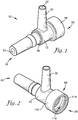
- the intravenous injection site 10 broadly comprises a luer body 12, a rotating threaded collar 14, and a split septum assembly 16.
- a cannula 18 or a needle may be inserted into the split septum assembly 16 for the administration of fluids, such as parenteral fluids or medicaments, to a patient.
- the rotating threaded collar 14 may be removably coupled with a catheter 20 intravenously inserted into the patient.
- the patient may be a human or an animal.
- the injection site 10 is described and illustrated with the catheter 20, the site 10 can also be used in other applications (e.g., with other types of connection components, tubing, etc.).
- a form factor of the intravenous injection site 10, i.e., a size and a shape of the luer body 12 and the split septum assembly 16, is miniaturized relative to standardized injection sites.
- the form factor operates particularly well with patients such as neonates and small animals.
- the intravenous injection site has an axial length of approximately less than 30.5 mm (1.2 inches), approximately less than 25.4 mm (1 inch), or approximately 24.6 mm (.97 inch) or 24.9 mm (.98 inch); and a transverse width at its widest point of approximately less than 12.7 mm (.5 inch), approximately less than 10.1 mm (.4 inch), or approximately 8.3 mm (.33 inch) or 8.6 mm (.34 inch).
- the injection site 10 and its components have axial lengths that extend in a direction of a fluid passageway 22 (see, Fig. 4 ), as described below.
- the injection site 10 and components also present a transverse width that is generally perpendicular to an axis of the fluid passageway 22.
- a distal end 24 of the injection site 10 and components is the end oriented towards a patient when the injection site is in use by a clinician (i.e., the end towards the catheter 20), and a proximal end 26 of the injection site 10 and components is the end oriented towards a clinician administering fluids to the patient (i.e., the end towards the split septum assembly 16).
- injection site 10 components are generally cylindrical to present a radius from the axis of the fluid passageway 22 and to an outermost radial surface of the component when the injection site 10 is viewed from either its proximal or distal end or otherwise viewed in a horizontal cross section. Therefore, reference to a "radial-most" surface refers to the surface that is bounded by the radius extending between the passageway axis and the particular surface. For clarity, the passageway axis generally bisects the fluid passageway 22.
- the luer body 12 is a slip luer T-site body comprising an elongated primary body portion 28 having the fluid passageway 22 formed therethrough, such that the fluid passageway 22 is a primary fluid passageway.
- a secondary body portion 30 extends generally perpendicularly from the primary body portion 28 and presents a secondary fluid passageway 32 (see, Fig. 4 ).
- the luer body 12 is in embodiments formed of a molded rigid thermoplastic resin (MAKROLON® by BAYER®).
- the primary and secondary body portions 28,30 of the luer body 12 are integrally formed to present a unitary, monolithic structure.
- the secondary body portion 30 may be removably coupled to the primary body portion 28, such as via threaded connectors (not shown).
- the secondary body portion 30 provides a secondary access point for the administration of fluids to the patient and via the secondary fluid passageway 32. As shown in Fig. 4 , the secondary fluid passageway 32 intersects the primary fluid passageway 22, such that fluids administered via the secondary body portion 30 flow to the primary fluid passageway 22. In use, the primary fluid passageway 22 is fluidly connected to the catheter 20 for administration of fluids intravenously, as discussed in more detail below.
- the primary fluid passageway 22 extends the axial length, or almost the entire axial length, of the primary body portion 28 of the luer body 12.
- the luer body 12 thus presents an axial length and proximal and distal ends.
- the rotating threaded collar 14 is coupled to the distal end 24 of the luer body 12, and the split septum assembly 16 is either integrally formed with or coupled to the proximal end 26 of the luer body 12, as described in more detail below.
- the primary fluid passageway 22 is an elongated opening formed through the primary body portion 28 of the luer body 12.
- a proximal segment 34 of the primary fluid passageway 22 is generally conical in shape, such that a width of the primary fluid passageway 22 tapers, i.e., narrows, from a proximal-most end of the fluid passageway 22 and towards a distal direction. That is, the conically-shaped proximal segment 34 presents fluid passageway walls 36 that are inwardly-angled in a distal direction. In embodiments, the angle of the conically-shaped proximal segment 34 is approximately 20-60 degrees, approximately 30-50 degrees, or is approximately 40 degrees. The conically-shaped proximal segment 34 assists in the location of a needle within the fluid passageway 22.
- the conically-shaped segment 34 of the fluid passageway 22 of embodiments of the invention allows room for a tip of the needle inserted at an angle relative to the transverse plane of the split septum assembly 16 to be guided into the fluid passageway 22 in a straighter orientation.
- the rotating threaded collar 14 includes an outer body 38 and a plurality of internal threads 40 for rotatably coupling the collar 14 to the distal end 24 of the primary body portion 28 of the luer body 12.
- the outer body 38 of the collar 14 may include a plurality of gripping protrusions 42 to allow the clinician to interconnect the collar 14 with the luer body 12.
- the plurality of internal threads 40 may be rotated onto the luer body 12, as best illustrated in Fig. 4 .
- the collar 14 may include various anti-rotation features, which are discussed in more detail below.
- the rotating collar 14 is removably coupled with the catheter 20 (see, Fig. 7 ).
- the catheter 20 generally comprises an annular proximal base 44 with diametrically opposed connection tabs 46 for threaded connection to the collar 14, an elongated barrel 48, and an elongated injection lumen 50 secured to the distal end of the barrel 48.
- Embodiments of the invention may also be used with other catheter designs, as well as other components permanently or removably secured to the injection site 10.
- the cannula 18 or needle may be inserted into the split septum assembly 16 at the proximal end 26 of the injection site 10.
- the cannula 18 comprises a proximal annular base 52 and an externally ribbed barrel 54 terminating in an elongated injection lumen 56.
- the base 52 is provided with diametrically opposed connection tabs 58 configured for threaded connection with a standard luer lock fitting (not shown).
- the cannula 18 is a "blunt cannula" formed of a relatively rigid plastic or stainless steel and intended to provide needleless connection with a septum.
- Cannulas are commonly used with humans, whereas for animals, such as dogs and cats, it is more common to use a needle.
- embodiments of the invention are for use with both cannulas and needles.
- the split septum assembly 16 of embodiments of the invention comprises a resilient and compressible split septum 60 having an axially-formed slit 62 for receipt of the blunt cannula 18, needle, or other medical device through said slit 62, a septum holder 64 for receipt of the split septum 60, and a septum housing 66 for receipt of the combined septum holder 64 and split septum 60.
- the septum 60, septum holder 64, and septum housing 66 are each independent and separated components, as opposed to being formed together.
- the combined septum holder 64 and septum 60 is frictionally held within the septum housing 66, as described in more detail below, as opposed to be ultrasonically welded together.
- the split septum assembly 16 is shown used with the luer body 12 that is a T-site body; however, the split septum assembly 16 may be used with other luer bodies.
- the split septum 60 is formed of a synthetic isoprene with silica filler that in embodiments is free of natural rubber, latex, or mercaptobenzimidazol and has a hardness of 36-41 Shore A. As noted above, the split septum 60 is resilient and compressible. As more fully described below, the septum 60 is compressible along both an axial length and a transverse width. The septum 60 is also hermetically sealed within the injection site 10 to significantly minimize or completely prevent the expulsion of fluids out of the slit 62 in the septum 60, such as may occur upon removal of the cannula 18 or needle. The septum 60 is formed as a single, monolithic unit.
- the "pre-use position,” as referenced herein, is the position of the septum 60 located in the septum holder 64, and the combined septum 60 and septum holder 64 located in the septum housing 66, as described below.
- the septum 60 In the pre-use position, the septum 60 is under compression due to being located in the septum holder 64 and septum housing 66, but the septum is not "in use” because the cannula 18, needle, or other medical device is not inserted in the septum 60.
- the "in use” position is when the cannula 18, needle, or other medical device is inserted into the septum 60.
- a “rest” or “neutral” position is when the septum 60 is not located in the septum holder 64 or the septum housing 66, i.e., the septum 60 is not under compression.
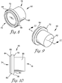
- the split septum 60 includes a generally cylindrical body 68 presenting a radial-most outer surface 70 having an outer diameter, and an annular flange 72 circumscribing the radial-most outer surface 70 of the septum body 68 at a distal end 74 of the septum body 68.
- a proximal end 76 of the septum body 68 is numbered in Figs. 8-10 for orientation purposes and ease of reference.
- Each of the cylindrical body 68 and the flange 72 has an axial length (i.e., the length along an axis of the fluid passageway 22 when the septum 60 is located in the luer body 12), and the axial length of the septum body 68 is greater than the axial length of the flange 72.
- the axial length of the septum body 68 is at least three times, five times, or ten times greater than the axial length of the flange 72. Transverse widths of the septum body 68 and the flange 72 are described below.
- the slit 62 is formed in the septum 60 and extends along the entire axial length of the septum body 68.
- a plurality of slits 62 may be formed in the septum 60.
- two slits 62 may be formed in the septum 60, and in embodiments, the slits 62 may be at generally ninety degrees to each other or at another angle.
- three or more slits 62 may be formed in the septum 60, such as tri-slit formed in a Y-shape as illustrated in Fig. 9 .
- the slit 62 When the septum 60 is in the pre-use or rest positions, the slit 62 is in a closed position, i.e., fluid does not flow through the slit 62. When the septum 60 is in the use position, the cannula 18, needle, or other medical device inserted into the slit 62 provides fluids that flow through the slit 62 and into the fluid passageway 22 of the injection site 10.
- the flange 72 extends radially from the septum body 68 to present a radial-most outer edge 78 of the flange 72 having an outer diameter of the flange 72, and this outer diameter of the flange 72 is greater than the outer diameter of the septum body 68.
- the flange 72 projects radially further along a transverse axis than the septum body 68.
- the flange 72 is located at the distal end 74 of the septum body 68, and in other embodiments, the flange is located at a distal-most end of the septum body 68, wherein the distal-most end of the septum body 68 is the terminal end presenting a distal terminus of the body.
- the flange 72 presents a proximal-most surface 80 and a distal-most surface 82, wherein each of the proximal-most and distal-most surfaces 80,82 has a transverse width to present respective proximal-most and distal-most transverse surfaces (also identified as reference numerals 80,82, respectively).
- An annular locating and sealing projection 84 is formed on the distal-most transverse surface 82 and extends distally from the surface 82.
- the annular locating and sealing projection 84 is endless in that it extends around the entire annular flange 72.
- a plurality of locating projections may be formed on the distal-most transverse surface 82 of the flange 72 and extend distally from the surface 72, as opposed to the single annular projection illustrated in the Figures.
- the projection 84 (whether in the embodiment of the single annular projection or the embodiment of the plurality of projections) has a radial-most outer edge 86.
- the radial-most outer edge 86 presents an outer diameter, and this outer diameter is less than the outer diameter of the flange 72, which, as noted above, is presented at the radial-most outer edge 78 of the flange 72.
- the difference in the radial lengths between the radial-most outer edge 78 of the flange 72 and the radial-most outer edge 86 of the projection 84 creates a shelf 88 defined by the transition from the radial-most outer edge 78 of the flange 72 to the radial-most outer edge 86 of the projection 84.
- a length from a center point of the septum 60 to the radial-most outer edge 78 of the flange 72 is larger than a length from the center point of the septum 60 to a radial-most outer edge of each projection to create a shelf defined by the transition from the radial-most outer edge 78 of the flange 72 to the radial-most outer edge of each projection.
- the purpose of the shelf 88 will be discussed in more detail below.
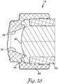
- the locating and sealing projection of both embodiments is frustoconically shaped when viewed in vertical cross section, as shown in Fig. 12 .
- the locating and sealing projection may be arcuate-shaped, such as hemispherical-shaped, or may be rectangular- or square-shaped when viewed in vertical cross section.
- a distal-most transverse surface 90 of the septum body 68 is generally arcuate relative to the fluid passageway 22 of the injection site 10. That is, the distal-most transverse surface 90 of the septum body 68 is not substantially flat. In yet further embodiments and as shown in Fig. 4 , the distal-most transverse surface 90 of the septum body 68 is concave relative to the fluid passageway 22 of the injection site 10, as illustrated in Fig. 4 . In even yet further embodiments, the distal-most transverse surface 90 of the septum body 68 is convex relative to the fluid passageway 22 of the injection site 10, as illustrated in Fig.
- a convex distal-most transverse surface 90 of the septum body 68 presents the advantage of a longer axial length of the slit 62.
- the septum body 68 is described and illustrated as generally cylindrical, such that the distal-most transverse surface 90 of the septum body 68 is also cylindrical when viewed at either the distal or proximal ends 74 of the body 68, the distal-most transverse surface 90 of the septum body 68 may also be other shapes, such as elliptical, oval, horizontal, square, rectangular, or generally arcuate in horizontal cross-section.
- a radial-most outer edge 92 of the distal-most transverse surface 90 of the septum body 68 lies in a transverse plane with the shelf 88 (hereinafter referred to as "the first shelf") created by the transition from the radial-most outer edge 78 of the flange 72 to the radial-most outer edge 86 of the locating and sealing projection 84.
- a second shelf 94 is created by the transition from a radial inner edge 96 of the projection 84 to the radial-most outer edge 92 of the transverse surface 90.
- the radial inner edge 96 of the projection 84 is, in embodiments, a radial-least inner edge, i.e., the inner edge portion of the projection 84 presenting the least distance from a center point of the septum 60 to the inner edge of the projection 84. This is due to the projection 84 having a frustoconical shape, such that there is a plurality of radii lengths from the center point of the septum 60 to the inner edge 96 of the projection 84.
- the first and second shelves 88,84 lie in the same transverse plane due to the projection 84 being integrally formed with the distal-most transverse surface 90 of the flange 72.
- the septum holder 64 is configured to receive the resilient and compressible split septum 60.
- the septum holder 64 is substantially rigid and has a generally cylindrically shaped body 98 presenting a radial-most outer surface 100 having an outer diameter and a radial-most inner surface 102 having an inner diameter. Due to its cylindrical shape, the septum holder 64 presents an open well 104 in which the septum body 68 is located. In embodiments of the invention, at least 50%, at least 80%, at least 90%, at least 95%, or 100% of the septum body 68 is located within the open well 104 of the septum holder 64.
- the axial length of the septum body 68 is at least 50%, at least 80%, at least 90%, at least 95%, or is the same as an axial length of the septum holder 64..
- the septum holder 64 further includes an annular locking ring 106 formed on the radial-most outer surface 100 of the septum holder body 98 and circumscribing the body.
- the annular locking ring 106 is endless in that it extends around the entire cylindrically-shaped septum holder body 98.
- a plurality of locking projections may be formed on the outer surface 100 of the body 98.
- the locking ring 106 is deformable in either or both of a transverse and axial direction. As described below, this is advantageous when inserting the septum holder 64 within the septum housing 66. Because the locking ring 106 is deformable, it has a pre-use shape that is generally symmetrical about a transverse axis and an in-use shape that is generally asymmetrical.
- the pre-use locking ring 106 is shown in Figs. 14-15 . As illustrated, the locking ring 106 is substantially hemispherical in horizontal cross section, although other symmetrical shapes could be used. In embodiments, the pre-use shape of the locking ring 106 is also arcuate when viewed in horizontal cross section. In alternative embodiments, the pre-use shape of the locking ring 106 may be generally frustoconical, rectangular, or square shaped.
- the in-use locking ring 106 is shown in Fig. 5 .
- the locking ring 106 is angled towards the proximal end 26 of the injection site 10 when the septum holder 64 is mounted within the septum housing 66.
- the locking ring 106 is not symmetrical about a transverse axis of the septum holder 64 when in-use.
- the locking ring 106 illustrated in Figs. 5 and 15 presents a bulbous end.
- the locking ring 106 is located at a substantial mid-point of an axial length of the septum holder 64, as best illustrated in Fig. 14 , such that the locking ring 106 generally bisects the axial length of the holder 64.
- the split septum 60 may be positioned within the septum holder 64 by locating the septum body 68 through either of a proximal or a distal end of the septum holder 64.
- the septum holder 64 allows bi-directional insertion of the septum 60 into the septum holder 64, such that the septum 60 can be located in the septum holder 64 from either axial direction of the septum holder 64.
- the locking ring 106 presents a radial-most outer surface 108 that has an outer diameter, and this outer diameter is larger than the outer diameter of the radial-most outer surface 100 of the septum holder body 98.
- the locking ring 106 extends transversely from the septum holder body 98.
- the septum 60 is frictionally held within the septum holder 64.
- the radial-most outer diameter of the septum body 68 is slightly larger than the radial-most inner diameter of the septum holder 64, but in other embodiments the radial-most outer diameter of the septum body 68 is substantially the same as the radial-most inner diameter of the septum holder 64.
- the friction between the resilient material of the septum body 68 and the septum holder 64 is sufficient to preassemble the septum 60 in the septum holder 64 prior to being assembled in the septum housing 66.
- the septum 60 undergoes a transverse compression upon insertion of the combined septum 60 and septum holder 64 in the septum housing 66.
- the septum housing 66 is integrally formed with the luer body 12 and extends from the proximal end of the luer body 12, such that the luer body 12 is a monolithic structure with the septum housing 66.
- the septum housing 66 is a separate unit from the luer body 12 and is coupled to the luer body 12 to provide the fluid passageway 22 through the injection site 10.
- the septum housing 66 presents a general cup-like opening 110 (hereinafter the "cup") for receipt of the combined septum holder 64 and the septum 60.
- the septum 60 is first positioned in the septum holder 64, and then the combined septum holder 64 and the septum 60 are positioned in the cup 110 of the septum housing 66.
- the cup 110 is generally cylindrically-shaped, such that a proximal end receives the combined septum holder 64 and the septum 60, and a distal end is fluidly connected to the fluid passageway 22 of the injection site 10.
- the septum housing 66 extends proximally from the distal end of the luer body 12, the angled fluid passageway walls 36 intersect the septum 60, and specifically the distal-most transverse surface 90 of the septum 60, held in the septum housing 66, as best illustrated in Fig. 4 .
- the cup 110 of the septum housing 66 presents a radial-most outer wall 112 (i.e., the external or outer wall of the cup 110 of the septum housing 66) and a radial-most inner wall 114 (i.e., the interior or inner wall of the cup 110 of the septum housing 66).
- An annular locating groove 116 is formed in a distal transverse surface 120 of the septum housing 66 for receipt of the annular locating and sealing projection 84 formed on the distal-most surface 82 of the flange 72, as further described below.
- an annular locking groove 118 is formed on the radial-most inner wall 114 of the cup 110 for receipt of the locking ring 106 formed on the septum holder body 98, as also described below.
- the radial-most outer wall 112 of the cup 110 presents an outer diameter of the septum housing 66, and the outer diameter of the septum housing 66 is substantially the same along an entire axial length of the septum housing 66.
- the radial-most inner wall 114 of the cup 110 presents a plurality of inner wall segments 114a,114b,114c corresponding to different inner diameters, as best illustrated in Fig. 5 .
- the inner diameter of the inner wall 114 is smallest at the distal-most end of the septum housing 66, where the inner wall 114 gradually angles outwardly as the proximal end of the septum housing 66 is approached for an axial length corresponding to a first inner wall segment 114a.
- first inner wall segment 114a which is located at approximately the radial-most outer edge 78 of the flange 72, has an inner diameter smaller than an innermost portion of a second inner wall segment 114b.
- the purpose for the first inner wall segment 114a to be angled is discussed further below.
- the inner wall 114 transitions from the first inner wall segment 114a to the locking groove 118 at a proximal-most end of the first inner wall segment 114a.
- the locking groove 118 is also discussed in more detail below.
- the inner wall 114 then transitions from the locking groove 118 to the second inner wall segment 114b, which is generally axially straight.
- the inner wall 114 transitions from the second inner wall segment 114 to a third inner wall segment 114c at a proximal-most end of the second inner wall segment 114b.
- the third inner wall segment 114c is sharply angled outwardly as the proximal end of the septum housing 66 is approached.
- the angle of the third inner wall segment 114c, relative to the straight second inner wall segment 114b is approximately 5-20 degrees, approximately 10-15 degrees, or approximately 12.6 degrees.
- the groove 116 is substantially complementary shaped with the shape of the projection 84.
- the locating groove 116 is also frustoconically shaped to receive the projection 84.
- An axial length of the annular projection 84 when positioned in the locating groove 116 is approximately .5 mm.
- the projection may not be annular but instead may comprise the plurality of projections.
- the annular locating groove may also not be annular and instead comprising a series of complementary-shaped openings for receipt of the respective plurality of projections.
- the annular locating groove 116 is formed in the distal transverse surface 120 of the septum housing 66.
- the distal transverse surface 120 of the septum housing 66 juts slightly inwardly towards the fluid passageway 22 to receive the projection 84 on the flange 72.
- the first shelf 88 of the flange 72 is defined by the transition from the radial-most outer edge 78 of the flange 72 to the radial-most outer edge 86 of the locating and sealing projection 84. Additionally, the second shelf 94 of the flange 72 is created by the transition from the radial inner edge 96 of the projection 84 to the radial-most outer edge 92 of the transverse surface 90 of the septum body 68.
- a barb 122 projects proximally from the distal transverse surface 120 of the septum housing 66 to assist in grasping the septum 60 when the septum 60 is positioned in the septum housing 66.
- the barb 122 is generally angled in a reverse V-shape, such that the barb 122 is pointed at its proximal end to push into the resilient and compressible material of the septum 60.
- the barb 122 will press into a portion of the second shelf 94 of the septum 60, which was described above.
- the locking groove 118 is generally arcuate along its axial length when viewed in cross section, as shown in Fig. 5 .
- the locking groove 118 comprises an axial wall 136 and transverse wall 138.
- the transverse wall 138 extends generally radially outwardly, and the axial wall 136 extends generally axially.
- the axial wall 136 curves into the transverse wall 138 to form a continuous, arcuate groove.
- the transverse wall 138 includes an inner edge 140 (which is the proximal-most end of the groove 118) that must be overcome for the locking ring 106 to snap-fit into the locking groove 118.
- the distal-most end of the axial wall 136 intersects the proximal-most edge of the first inner wall segment 114a. As the proximal end of the axial wall 136 is approached, the axial wall 136 tapers radially outwardly. At approximately the axial wall's radially-most outward end, the axial wall 136 transitions to the transverse wall 138 as the proximal end of the locking groove 118 is approached. The transverse wall 138 then curves radially inwardly to intersect the distal-most edge of the second inner wall segment 114b.
- the locking groove 118 thus forms the general shape of half of a heart, as illustrated in Fig. 5 . However, it should be appreciated that the locking groove 118 may be other shapes.
- the locking groove 118 is, in embodiments of the invention, not complementary shaped to either of the pre-use or in-use shapes of the locking ring 106 transversely extending from and formed on the septum holder body 98. Instead, the locking groove 118 provides a depression that is shaped to allow the locking ring 106 to slide into the locking groove 118, deform, and snap-fit into a locked position. More particularly, when the locking ring 106 is in place within the locking groove 118, an area 124 of the locking groove 118 distal of the locking ring 106 is open (i.e., not filled with the locking ring 106), and this open area 124 is more than any open area of the locking groove 118 proximal of the locking ring 106.
- a bulbous end of the locking ring 106 is located at the proximal end of the locking groove 118.
- the locking ring 106 overcomes the proximal-most edge of the locking groove 118, the locking ring 106 deforms proximally (i.e., it is manipulated by the interaction with the locking groove 118 to be deformed proximally), such that the locking ring 106 forms the bulbous end that presses against the transverse wall 138 of the locking groove 118. Because the locking ring 106 is, in embodiments, deformable in either or both of a transverse or axial direction, this allows sufficient movement or "give" of the bulbous end of the locking ring 106 to deform into position within the locking groove 118.
- the third inner wall segment 114c of the septum housing 66 is angled sharply outwardly as the proximal end of the septum housing 66 is approached. The sharp angle facilitates locating the septum holder 64 in the septum housing 66.
- the locking ring 106 on the septum holder 64 is snap-fit into position within the locking groove 118. During positioning of the septum holder 64 in the septum housing 66, the locking ring 106 slides against the angled third inner wall segment 114c, which slightly compresses the septum holder 64 inwardly along a transverse axis. Upon the locking ring 106 being received in the locking groove 118, the septum holder 64 retracts axially outward.
- a distal segment of the septum holder 64 i.e., the segment of the septum holder 66 extending generally distally from the locking ring 106, is compressed radially inwardly along the transverse axis.
- the radial inward compression of the septum holder 66 is relatively small, e.g., approximately .1 mm, this compression in turn translates to the septum 60 located in the septum holder 66 to also compress the septum 60 radially inwardly along the transverse axis.
- the components of the split septum assembly 16 of embodiments of the invention collectively work together to compress the septum 60 radially inwardly along a transverse axis and at the distal end 74 of the septum body 68.
- the outer diameter of the radial-most outer edge 78 of the flange 72 is less than the radial-most inner diameter of the septum holder 64 to present a gap 126 between the radial-most outer edge 78 of the flange 72 and the first inner wall segment 114a of the septum housing 66.
- the gap 126 provides an open area in which the septum flange 72 may expand radially upon insertion of the cannula 18, needle, etc.
- a volume of the septum 60 is displaced upon insertion of the cannula 18, and this displaced volume of the septum 60 must be able to expand into an open area.
- the expansion occurs along the proximal or distal transverse surfaces of the septum 60.
- the distal-most transverse surface 90 of the septum body 68 does not experience any distal displacement upon insertion of the cannula 18, needle, etc. That is, when the cannula 18 is inserted into the septum 60, the distal-most transverse surface 90 does not expand or otherwise move into the fluid passageway 22.
- the location of the distal-most transverse surface 90 of the septum 60 in a rest state is in the same position as an in use state when the cannula 18 is inserted into the septum 60.
- a proximal-most transverse surface of the septum body 68 is displaced proximally beyond a proximal-most horizontal plane of the septum holder 64.
- Positioning of the combined septum holder 64 and septum 60 in the septum housing 66 also axially compresses the flange 72 of the septum 60 to present a double hermetic seal.
- the flange 72 compresses axially in a distal direction approximately .1 mm from its rest position when held within the septum holder 64, to its pre-use position when the combined septum holder 64 and septum 60 are positioned in the septum housing 66.
- a first hermetic seal is formed at and around the second shelf 94, such that fluid from the fluid passageway 22 does not leak between the distal-most surface 82 of the flange 72 and the distal transverse surface 120 of the septum housing 66.
- a second hermetic seal is formed at the first shelf 88to prevent fluid from leaking into the gap 126 between the radial-most outer edge 78 of the flange 72 and the septum holder 64.
- the septum 60 is hermetically sealed within the injection site 10 to minimize or completely prevent the proximal expulsion of fluids out of the slit 62 in the septum 60 or around the septum holder 64, such as may occur upon removal of the cannula 18 or needle.
- the receipt of the projection 84 within the locating groove 116 serves to prevent entrapment of fluids underneath the projection 84 and the flange 72.
- the threaded rotating collar 14 includes an annular anti-rotation ring 128 extending annularly around a proximal end of the rotating collar 14.
- the anti-rotation ring 128 is formed on a distal facing transverse surface 130 of the collar 14 and extends distally from the surface 130.
- the ring 128 is slightly tapered as it extends distally to its terminus 132.
- the ring 128 acts as a stop as the plurality of threads 40 of the collar 14 are rotated about the luer body 12.
- the ring 128 prevents the threaded collar 14 from rotating proximally further. Additionally, the ring 128 provides enough frictional stoppage to require a relatively large initial force to reverse rotation of the threaded collar 14 to remove the collar 14 from the luer body 12.
- the anti-rotation ring 128 operates in conjunction with an inwardly transversely extending barb 134 that also extends proximally upwards from the luer body 12. The barb 134 serves to catch the anti-rotation ring 128 and provide frictional resistance to prevent further rotation of the collar 14 or prevent rotation in a reverse direction.
Applications Claiming Priority (2)
| Application Number | Priority Date | Filing Date | Title |
|---|---|---|---|
| US201461937804P | 2014-02-10 | 2014-02-10 | |
| US14/613,561 US9987477B2 (en) | 2014-02-10 | 2015-02-04 | Split septum assembly for an intravenous injection site |
Publications (3)
| Publication Number | Publication Date |
|---|---|
| EP2923725A2 EP2923725A2 (en) | 2015-09-30 |
| EP2923725A3 EP2923725A3 (en) | 2015-12-30 |
| EP2923725B1 true EP2923725B1 (en) | 2017-11-01 |
Family
ID=53774029
Family Applications (1)
| Application Number | Title | Priority Date | Filing Date |
|---|---|---|---|
| EP15154060.6A Active EP2923725B1 (en) | 2014-02-10 | 2015-02-06 | Split septum assembly for an intravenous injection site |
Country Status (4)
| Country | Link |
|---|---|
| US (1) | US9987477B2 (es) |
| EP (1) | EP2923725B1 (es) |
| CA (1) | CA2881294C (es) |
| ES (1) | ES2649974T3 (es) |
Families Citing this family (16)
| Publication number | Priority date | Publication date | Assignee | Title |
|---|---|---|---|---|
| US10525237B2 (en) | 2015-10-28 | 2020-01-07 | Becton, Dickinson And Company | Ergonomic IV systems and methods |
| US10245416B2 (en) | 2015-10-28 | 2019-04-02 | Becton, Dickinson And Company | Intravenous catheter device with integrated extension tube |
| US10639455B2 (en) | 2015-10-28 | 2020-05-05 | Becton, Dickinson And Company | Closed IV access device with paddle grip needle hub and flash chamber |
| US10357636B2 (en) | 2015-10-28 | 2019-07-23 | Becton, Dickinson And Company | IV access device having an angled paddle grip |
| US10549072B2 (en) | 2015-10-28 | 2020-02-04 | Becton, Dickinson And Company | Integrated catheter with independent fluid paths |
| US10814106B2 (en) | 2015-10-28 | 2020-10-27 | Becton, Dickinson And Company | Soft push tabs for catheter adapter |
| US10744305B2 (en) | 2015-10-28 | 2020-08-18 | Becton, Dickinson And Company | Ergonomic IV systems and methods |
| USD837368S1 (en) | 2016-10-05 | 2019-01-01 | Becton, Dickinson And Company | Catheter adapter grip |
| USD835262S1 (en) | 2016-10-05 | 2018-12-04 | Becton, Dickinson And Company | Intravenous catheter assembly |
| US10238852B2 (en) * | 2016-10-05 | 2019-03-26 | Becton, Dickinson And Company | Septum housing |
| USD819802S1 (en) | 2016-10-05 | 2018-06-05 | Becton, Dickinson And Company | Catheter adapter |
| USD844781S1 (en) | 2016-10-05 | 2019-04-02 | Becton, Dickinson And Company | Needle hub |
| JP6826458B2 (ja) * | 2017-02-17 | 2021-02-03 | テルモ株式会社 | 医療用コネクタ及び輸液セット |
| US10512755B2 (en) * | 2017-06-08 | 2019-12-24 | Becton, Dickinson And Company | Septum securement |
| DE102020202939A1 (de) | 2020-03-06 | 2021-09-09 | B. Braun Melsungen Aktiengesellschaft | Kupplungselement für ein geschlossenes Fluidtransfersystem, Gegenkupplungselement für ein solches Kupplungselement sowie Kupplungssystem |
| US11690993B1 (en) | 2022-01-12 | 2023-07-04 | Nexus Medical, Llc | Coupling apparatus for infusion device |
Family Cites Families (4)
| Publication number | Priority date | Publication date | Assignee | Title |
|---|---|---|---|---|
| IL130482A0 (en) | 1996-12-16 | 2000-06-01 | Icu Medical Inc | Positive flow valve |
| US8211089B2 (en) | 2006-03-24 | 2012-07-03 | Nexus Medical, Llc | Intravenous injection site with split septum and pressure activated flow control valve |
| US8337483B2 (en) * | 2006-11-02 | 2012-12-25 | Becton, Dickinson And Company | Vascular access device chamber replacement |
| FR2910817B1 (fr) * | 2007-01-03 | 2009-02-13 | Vygon Sa | Connecteur pour etablir une communication de fluide sous le controle d'une valve, notamment a usage dans le domaine medical |
-
2015
- 2015-02-04 US US14/613,561 patent/US9987477B2/en active Active
- 2015-02-05 CA CA2881294A patent/CA2881294C/en active Active
- 2015-02-06 EP EP15154060.6A patent/EP2923725B1/en active Active
- 2015-02-06 ES ES15154060.6T patent/ES2649974T3/es active Active
Non-Patent Citations (1)
| Title |
|---|
| None * |
Also Published As
| Publication number | Publication date |
|---|---|
| CA2881294C (en) | 2017-09-19 |
| US20150224296A1 (en) | 2015-08-13 |
| ES2649974T3 (es) | 2018-01-16 |
| EP2923725A2 (en) | 2015-09-30 |
| EP2923725A3 (en) | 2015-12-30 |
| CA2881294A1 (en) | 2015-08-10 |
| US9987477B2 (en) | 2018-06-05 |
Similar Documents
| Publication | Publication Date | Title |
|---|---|---|
| EP2923725B1 (en) | Split septum assembly for an intravenous injection site | |
| CA2524678C (en) | Self-sealing male connector | |
| JP5632491B2 (ja) | 安全機構付き薬物送達コネクタ | |
| US6146362A (en) | Needleless IV medical delivery system | |
| US6050978A (en) | Needleless valve connector | |
| ES2809398T3 (es) | Jeringa de enjuague de desplazamiento positivo | |
| US5833674A (en) | Needleless IV medical delivery system | |
| CN107913444B (zh) | 导管组件 | |
| CA2808051C (en) | Collet lock | |
| AU2017306658B2 (en) | Intravenous catheter apparatus with safety function and pressure controlled valve element | |
| US20110015580A1 (en) | Devices, assemblies, and methods for controlling fluid flow | |
| US10245418B2 (en) | Apparatus for a medical system inflation syringe | |
| US11944792B2 (en) | Flush syringe with flip cap | |
| JP2005525836A (ja) | ニードルハブアッセンブリ | |
| CN216258735U (zh) | 一种盖帽 | |
| WO2009144599A1 (en) | Luer tip activated flow control device | |
| CN215460311U (zh) | 具有卡扣式肠内连接特征的注射器 |
Legal Events
| Date | Code | Title | Description |
|---|---|---|---|
| PUAI | Public reference made under article 153(3) epc to a published international application that has entered the european phase |
Free format text: ORIGINAL CODE: 0009012 |
|
| AK | Designated contracting states |
Kind code of ref document: A2 Designated state(s): AL AT BE BG CH CY CZ DE DK EE ES FI FR GB GR HR HU IE IS IT LI LT LU LV MC MK MT NL NO PL PT RO RS SE SI SK SM TR |
|
| AX | Request for extension of the european patent |
Extension state: BA ME |
|
| PUAL | Search report despatched |
Free format text: ORIGINAL CODE: 0009013 |
|
| AK | Designated contracting states |
Kind code of ref document: A3 Designated state(s): AL AT BE BG CH CY CZ DE DK EE ES FI FR GB GR HR HU IE IS IT LI LT LU LV MC MK MT NL NO PL PT RO RS SE SI SK SM TR |
|
| AX | Request for extension of the european patent |
Extension state: BA ME |
|
| RIC1 | Information provided on ipc code assigned before grant |
Ipc: A61M 39/04 20060101ALI20151120BHEP Ipc: A61M 39/00 20060101AFI20151120BHEP |
|
| 17P | Request for examination filed |
Effective date: 20160630 |
|
| RBV | Designated contracting states (corrected) |
Designated state(s): AL AT BE BG CH CY CZ DE DK EE ES FI FR GB GR HR HU IE IS IT LI LT LU LV MC MK MT NL NO PL PT RO RS SE SI SK SM TR |
|
| GRAP | Despatch of communication of intention to grant a patent |
Free format text: ORIGINAL CODE: EPIDOSNIGR1 |
|
| INTG | Intention to grant announced |
Effective date: 20170530 |
|
| GRAS | Grant fee paid |
Free format text: ORIGINAL CODE: EPIDOSNIGR3 |
|
| GRAA | (expected) grant |
Free format text: ORIGINAL CODE: 0009210 |
|
| AK | Designated contracting states |
Kind code of ref document: B1 Designated state(s): AL AT BE BG CH CY CZ DE DK EE ES FI FR GB GR HR HU IE IS IT LI LT LU LV MC MK MT NL NO PL PT RO RS SE SI SK SM TR |
|
| REG | Reference to a national code |
Ref country code: GB Ref legal event code: FG4D |
|
| REG | Reference to a national code |
Ref country code: CH Ref legal event code: EP Ref country code: AT Ref legal event code: REF Ref document number: 941440 Country of ref document: AT Kind code of ref document: T Effective date: 20171115 |
|
| REG | Reference to a national code |
Ref country code: IE Ref legal event code: FG4D |
|
| REG | Reference to a national code |
Ref country code: DE Ref legal event code: R096 Ref document number: 602015005642 Country of ref document: DE |
|
| REG | Reference to a national code |
Ref country code: FR Ref legal event code: PLFP Year of fee payment: 4 |
|
| REG | Reference to a national code |
Ref country code: ES Ref legal event code: FG2A Ref document number: 2649974 Country of ref document: ES Kind code of ref document: T3 Effective date: 20180116 |
|
| REG | Reference to a national code |
Ref country code: NL Ref legal event code: MP Effective date: 20171101 |
|
| REG | Reference to a national code |
Ref country code: LT Ref legal event code: MG4D |
|
| REG | Reference to a national code |
Ref country code: AT Ref legal event code: MK05 Ref document number: 941440 Country of ref document: AT Kind code of ref document: T Effective date: 20171101 |
|
| PG25 | Lapsed in a contracting state [announced via postgrant information from national office to epo] |
Ref country code: NL Free format text: LAPSE BECAUSE OF FAILURE TO SUBMIT A TRANSLATION OF THE DESCRIPTION OR TO PAY THE FEE WITHIN THE PRESCRIBED TIME-LIMIT Effective date: 20171101 Ref country code: FI Free format text: LAPSE BECAUSE OF FAILURE TO SUBMIT A TRANSLATION OF THE DESCRIPTION OR TO PAY THE FEE WITHIN THE PRESCRIBED TIME-LIMIT Effective date: 20171101 Ref country code: NO Free format text: LAPSE BECAUSE OF FAILURE TO SUBMIT A TRANSLATION OF THE DESCRIPTION OR TO PAY THE FEE WITHIN THE PRESCRIBED TIME-LIMIT Effective date: 20180201 Ref country code: LT Free format text: LAPSE BECAUSE OF FAILURE TO SUBMIT A TRANSLATION OF THE DESCRIPTION OR TO PAY THE FEE WITHIN THE PRESCRIBED TIME-LIMIT Effective date: 20171101 Ref country code: SE Free format text: LAPSE BECAUSE OF FAILURE TO SUBMIT A TRANSLATION OF THE DESCRIPTION OR TO PAY THE FEE WITHIN THE PRESCRIBED TIME-LIMIT Effective date: 20171101 |
|
| PG25 | Lapsed in a contracting state [announced via postgrant information from national office to epo] |
Ref country code: BG Free format text: LAPSE BECAUSE OF FAILURE TO SUBMIT A TRANSLATION OF THE DESCRIPTION OR TO PAY THE FEE WITHIN THE PRESCRIBED TIME-LIMIT Effective date: 20180201 Ref country code: LV Free format text: LAPSE BECAUSE OF FAILURE TO SUBMIT A TRANSLATION OF THE DESCRIPTION OR TO PAY THE FEE WITHIN THE PRESCRIBED TIME-LIMIT Effective date: 20171101 Ref country code: GR Free format text: LAPSE BECAUSE OF FAILURE TO SUBMIT A TRANSLATION OF THE DESCRIPTION OR TO PAY THE FEE WITHIN THE PRESCRIBED TIME-LIMIT Effective date: 20180202 Ref country code: HR Free format text: LAPSE BECAUSE OF FAILURE TO SUBMIT A TRANSLATION OF THE DESCRIPTION OR TO PAY THE FEE WITHIN THE PRESCRIBED TIME-LIMIT Effective date: 20171101 Ref country code: AT Free format text: LAPSE BECAUSE OF FAILURE TO SUBMIT A TRANSLATION OF THE DESCRIPTION OR TO PAY THE FEE WITHIN THE PRESCRIBED TIME-LIMIT Effective date: 20171101 Ref country code: RS Free format text: LAPSE BECAUSE OF FAILURE TO SUBMIT A TRANSLATION OF THE DESCRIPTION OR TO PAY THE FEE WITHIN THE PRESCRIBED TIME-LIMIT Effective date: 20171101 Ref country code: IS Free format text: LAPSE BECAUSE OF FAILURE TO SUBMIT A TRANSLATION OF THE DESCRIPTION OR TO PAY THE FEE WITHIN THE PRESCRIBED TIME-LIMIT Effective date: 20180301 |
|
| PG25 | Lapsed in a contracting state [announced via postgrant information from national office to epo] |
Ref country code: CZ Free format text: LAPSE BECAUSE OF FAILURE TO SUBMIT A TRANSLATION OF THE DESCRIPTION OR TO PAY THE FEE WITHIN THE PRESCRIBED TIME-LIMIT Effective date: 20171101 Ref country code: EE Free format text: LAPSE BECAUSE OF FAILURE TO SUBMIT A TRANSLATION OF THE DESCRIPTION OR TO PAY THE FEE WITHIN THE PRESCRIBED TIME-LIMIT Effective date: 20171101 Ref country code: CY Free format text: LAPSE BECAUSE OF FAILURE TO SUBMIT A TRANSLATION OF THE DESCRIPTION OR TO PAY THE FEE WITHIN THE PRESCRIBED TIME-LIMIT Effective date: 20171101 Ref country code: DK Free format text: LAPSE BECAUSE OF FAILURE TO SUBMIT A TRANSLATION OF THE DESCRIPTION OR TO PAY THE FEE WITHIN THE PRESCRIBED TIME-LIMIT Effective date: 20171101 Ref country code: SK Free format text: LAPSE BECAUSE OF FAILURE TO SUBMIT A TRANSLATION OF THE DESCRIPTION OR TO PAY THE FEE WITHIN THE PRESCRIBED TIME-LIMIT Effective date: 20171101 |
|
| REG | Reference to a national code |
Ref country code: DE Ref legal event code: R097 Ref document number: 602015005642 Country of ref document: DE |
|
| PG25 | Lapsed in a contracting state [announced via postgrant information from national office to epo] |
Ref country code: RO Free format text: LAPSE BECAUSE OF FAILURE TO SUBMIT A TRANSLATION OF THE DESCRIPTION OR TO PAY THE FEE WITHIN THE PRESCRIBED TIME-LIMIT Effective date: 20171101 Ref country code: SM Free format text: LAPSE BECAUSE OF FAILURE TO SUBMIT A TRANSLATION OF THE DESCRIPTION OR TO PAY THE FEE WITHIN THE PRESCRIBED TIME-LIMIT Effective date: 20171101 Ref country code: PL Free format text: LAPSE BECAUSE OF FAILURE TO SUBMIT A TRANSLATION OF THE DESCRIPTION OR TO PAY THE FEE WITHIN THE PRESCRIBED TIME-LIMIT Effective date: 20171101 |
|
| PLBE | No opposition filed within time limit |
Free format text: ORIGINAL CODE: 0009261 |
|
| STAA | Information on the status of an ep patent application or granted ep patent |
Free format text: STATUS: NO OPPOSITION FILED WITHIN TIME LIMIT |
|
| REG | Reference to a national code |
Ref country code: CH Ref legal event code: PL |
|
| PG25 | Lapsed in a contracting state [announced via postgrant information from national office to epo] |
Ref country code: MC Free format text: LAPSE BECAUSE OF FAILURE TO SUBMIT A TRANSLATION OF THE DESCRIPTION OR TO PAY THE FEE WITHIN THE PRESCRIBED TIME-LIMIT Effective date: 20171101 |
|
| 26N | No opposition filed |
Effective date: 20180802 |
|
| REG | Reference to a national code |
Ref country code: BE Ref legal event code: MM Effective date: 20180228 |
|
| PG25 | Lapsed in a contracting state [announced via postgrant information from national office to epo] |
Ref country code: CH Free format text: LAPSE BECAUSE OF NON-PAYMENT OF DUE FEES Effective date: 20180228 Ref country code: LU Free format text: LAPSE BECAUSE OF NON-PAYMENT OF DUE FEES Effective date: 20180206 Ref country code: LI Free format text: LAPSE BECAUSE OF NON-PAYMENT OF DUE FEES Effective date: 20180228 Ref country code: SI Free format text: LAPSE BECAUSE OF FAILURE TO SUBMIT A TRANSLATION OF THE DESCRIPTION OR TO PAY THE FEE WITHIN THE PRESCRIBED TIME-LIMIT Effective date: 20171101 |
|
| REG | Reference to a national code |
Ref country code: IE Ref legal event code: MM4A |
|
| PG25 | Lapsed in a contracting state [announced via postgrant information from national office to epo] |
Ref country code: IE Free format text: LAPSE BECAUSE OF NON-PAYMENT OF DUE FEES Effective date: 20180206 |
|
| PG25 | Lapsed in a contracting state [announced via postgrant information from national office to epo] |
Ref country code: BE Free format text: LAPSE BECAUSE OF NON-PAYMENT OF DUE FEES Effective date: 20180228 |
|
| PG25 | Lapsed in a contracting state [announced via postgrant information from national office to epo] |
Ref country code: MT Free format text: LAPSE BECAUSE OF NON-PAYMENT OF DUE FEES Effective date: 20180206 |
|
| PG25 | Lapsed in a contracting state [announced via postgrant information from national office to epo] |
Ref country code: TR Free format text: LAPSE BECAUSE OF FAILURE TO SUBMIT A TRANSLATION OF THE DESCRIPTION OR TO PAY THE FEE WITHIN THE PRESCRIBED TIME-LIMIT Effective date: 20171101 |
|
| PG25 | Lapsed in a contracting state [announced via postgrant information from national office to epo] |
Ref country code: PT Free format text: LAPSE BECAUSE OF FAILURE TO SUBMIT A TRANSLATION OF THE DESCRIPTION OR TO PAY THE FEE WITHIN THE PRESCRIBED TIME-LIMIT Effective date: 20171101 |
|
| PG25 | Lapsed in a contracting state [announced via postgrant information from national office to epo] |
Ref country code: MK Free format text: LAPSE BECAUSE OF NON-PAYMENT OF DUE FEES Effective date: 20171101 Ref country code: HU Free format text: LAPSE BECAUSE OF FAILURE TO SUBMIT A TRANSLATION OF THE DESCRIPTION OR TO PAY THE FEE WITHIN THE PRESCRIBED TIME-LIMIT; INVALID AB INITIO Effective date: 20150206 |
|
| PG25 | Lapsed in a contracting state [announced via postgrant information from national office to epo] |
Ref country code: AL Free format text: LAPSE BECAUSE OF FAILURE TO SUBMIT A TRANSLATION OF THE DESCRIPTION OR TO PAY THE FEE WITHIN THE PRESCRIBED TIME-LIMIT Effective date: 20171101 |
|
| PGFP | Annual fee paid to national office [announced via postgrant information from national office to epo] |
Ref country code: GB Payment date: 20221215 Year of fee payment: 9 Ref country code: FR Payment date: 20221208 Year of fee payment: 9 |
|
| PGFP | Annual fee paid to national office [announced via postgrant information from national office to epo] |
Ref country code: ES Payment date: 20230310 Year of fee payment: 9 |
|
| PGFP | Annual fee paid to national office [announced via postgrant information from national office to epo] |
Ref country code: IT Payment date: 20230110 Year of fee payment: 9 Ref country code: DE Payment date: 20221213 Year of fee payment: 9 |
|
| P01 | Opt-out of the competence of the unified patent court (upc) registered |
Effective date: 20230526 |
|
| PGFP | Annual fee paid to national office [announced via postgrant information from national office to epo] |
Ref country code: ES Payment date: 20240305 Year of fee payment: 10 |