EP2923077B1 - Rotor de turbine éolienne et ses procédés d'assemblage - Google Patents
Rotor de turbine éolienne et ses procédés d'assemblage Download PDFInfo
- Publication number
- EP2923077B1 EP2923077B1 EP13801942.7A EP13801942A EP2923077B1 EP 2923077 B1 EP2923077 B1 EP 2923077B1 EP 13801942 A EP13801942 A EP 13801942A EP 2923077 B1 EP2923077 B1 EP 2923077B1
- Authority
- EP
- European Patent Office
- Prior art keywords
- rotor
- coupled
- blade
- structural member
- shaft
- Prior art date
- Legal status (The legal status is an assumption and is not a legal conclusion. Google has not performed a legal analysis and makes no representation as to the accuracy of the status listed.)
- Active
Links
- 238000000034 method Methods 0.000 title claims description 24
- 230000008878 coupling Effects 0.000 claims description 18
- 238000010168 coupling process Methods 0.000 claims description 18
- 238000005859 coupling reaction Methods 0.000 claims description 18
- 238000005452 bending Methods 0.000 description 11
- 238000004519 manufacturing process Methods 0.000 description 6
- 230000000712 assembly Effects 0.000 description 4
- 238000000429 assembly Methods 0.000 description 4
- 238000013016 damping Methods 0.000 description 4
- 239000000463 material Substances 0.000 description 4
- 238000009434 installation Methods 0.000 description 3
- 239000006096 absorbing agent Substances 0.000 description 2
- 229910045601 alloy Inorganic materials 0.000 description 2
- 239000000956 alloy Substances 0.000 description 2
- -1 but not limited to Substances 0.000 description 2
- 238000006243 chemical reaction Methods 0.000 description 2
- 238000000576 coating method Methods 0.000 description 2
- 239000002131 composite material Substances 0.000 description 2
- 229910052751 metal Inorganic materials 0.000 description 2
- 239000002184 metal Substances 0.000 description 2
- 150000002739 metals Chemical class 0.000 description 2
- 239000004033 plastic Substances 0.000 description 2
- 229920003023 plastic Polymers 0.000 description 2
- 230000035939 shock Effects 0.000 description 2
- 239000011800 void material Substances 0.000 description 2
- 229910001018 Cast iron Inorganic materials 0.000 description 1
- 238000010276 construction Methods 0.000 description 1
- 230000007423 decrease Effects 0.000 description 1
- 230000003247 decreasing effect Effects 0.000 description 1
- 230000009977 dual effect Effects 0.000 description 1
- 230000000694 effects Effects 0.000 description 1
- 230000005611 electricity Effects 0.000 description 1
Images


Classifications
-
- F—MECHANICAL ENGINEERING; LIGHTING; HEATING; WEAPONS; BLASTING
- F03—MACHINES OR ENGINES FOR LIQUIDS; WIND, SPRING, OR WEIGHT MOTORS; PRODUCING MECHANICAL POWER OR A REACTIVE PROPULSIVE THRUST, NOT OTHERWISE PROVIDED FOR
- F03D—WIND MOTORS
- F03D1/00—Wind motors with rotation axis substantially parallel to the air flow entering the rotor
- F03D1/06—Rotors
- F03D1/065—Rotors characterised by their construction elements
- F03D1/0658—Arrangements for fixing wind-engaging parts to a hub
-
- F—MECHANICAL ENGINEERING; LIGHTING; HEATING; WEAPONS; BLASTING
- F03—MACHINES OR ENGINES FOR LIQUIDS; WIND, SPRING, OR WEIGHT MOTORS; PRODUCING MECHANICAL POWER OR A REACTIVE PROPULSIVE THRUST, NOT OTHERWISE PROVIDED FOR
- F03D—WIND MOTORS
- F03D1/00—Wind motors with rotation axis substantially parallel to the air flow entering the rotor
- F03D1/06—Rotors
- F03D1/0608—Rotors characterised by their aerodynamic shape
- F03D1/0625—Rotors characterised by their aerodynamic shape of the whole rotor, i.e. form features of the rotor unit
-
- F—MECHANICAL ENGINEERING; LIGHTING; HEATING; WEAPONS; BLASTING
- F03—MACHINES OR ENGINES FOR LIQUIDS; WIND, SPRING, OR WEIGHT MOTORS; PRODUCING MECHANICAL POWER OR A REACTIVE PROPULSIVE THRUST, NOT OTHERWISE PROVIDED FOR
- F03D—WIND MOTORS
- F03D1/00—Wind motors with rotation axis substantially parallel to the air flow entering the rotor
- F03D1/06—Rotors
- F03D1/065—Rotors characterised by their construction elements
- F03D1/0691—Rotors characterised by their construction elements of the hub
-
- Y—GENERAL TAGGING OF NEW TECHNOLOGICAL DEVELOPMENTS; GENERAL TAGGING OF CROSS-SECTIONAL TECHNOLOGIES SPANNING OVER SEVERAL SECTIONS OF THE IPC; TECHNICAL SUBJECTS COVERED BY FORMER USPC CROSS-REFERENCE ART COLLECTIONS [XRACs] AND DIGESTS
- Y02—TECHNOLOGIES OR APPLICATIONS FOR MITIGATION OR ADAPTATION AGAINST CLIMATE CHANGE
- Y02E—REDUCTION OF GREENHOUSE GAS [GHG] EMISSIONS, RELATED TO ENERGY GENERATION, TRANSMISSION OR DISTRIBUTION
- Y02E10/00—Energy generation through renewable energy sources
- Y02E10/70—Wind energy
- Y02E10/72—Wind turbines with rotation axis in wind direction
Definitions
- the embodiments described herein relate generally to wind turbines, and more particularly, to methods and systems for improving efficiency of a wind turbine rotor.
- Some wind turbines may include a cast iron hub coupled to a shaft of a wind turbine, wherein the blades are coupled to the hub. More particularly, conventional wind turbine rotors may use a three-bladed configuration wherein root ends of the blades are coupled to the hub. These root ends, however, may not be aerodynamically shaped and may not produce power from the wind. More particularly, a portion of the blade near the root end may not produce any appreciable aerodynamic lift.
- the aerodynamic efficiency of the wind turbine may be improved by increasing the blade size of the wind turbine.
- Increasing the blade size usually involves increasing the size of other components and machinery of the wind turbine which may lead to higher wind turbine costs. More particularly, transportation costs, fabrication costs and/or installation costs can increase for larger sized blades.
- increasing the blade size may result in a higher load on a pitch assembly and a yaw assembly, and in particular, the respective bearings of these assemblies due to bending moments and/or thrust forces created by large rotor blades. More particularly, bending moments and/or thrust forces can override the charging limit of typical bearings.
- WO2010040829 discloses a tower provided at the top with a horizontal shaft having an axis.
- a turbine rotor comprises turbine blades connected by a mounting arrangement to bearing members and to a rotor or a generator. Components of forces acting on the blades parallel to the axis are substantially exclusively communicated to the bearing members, for example by rigid straight members.
- Torque about the axis produced by the blades is communicated substantially exclusively to the rotor through a member.
- JP 2005 282451 relates to a wind powered electricity generation apparatus which provide a wind power generator which provides a higher wind power generating efficiency even if larger-sized.
- a rotor coupled to a shaft includes a space frame hub having a central portion coupled to the shaft and a first structural member, a second structural member, and a third structural member coupled to the central portion, wherein the first structural member, the second structural member, and the third structural member having a first length.
- the rotor further includes a first blade coupled to the first structural member, a second blade coupled to the second structural member, and a third blade coupled to the third structural member and each having a tip end spaced from the shaft at a second length that is longer than the first length.
- a wind turbine in another aspect, includes a tower; a nacelle coupled to the tower; a shaft coupled to the nacelle; and a rotor coupled to the tower.
- the rotor includes a space frame hub having a central portion coupled to the shaft.
- a plurality of structural members is coupled to the central portion, wherein each member of the plurality of structural members has a first length.
- the rotor further includes a plurality of blades, wherein each blade of the plurality of blades is coupled to a respective portion of the plurality of portions and each blade has a tip end spaced from the shaft at a second length that is longer than the first length.
- a pitch assembly is coupled to each portion of the plurality of portions and to each blade of the plurality of blades.
- a method of assembling a rotor to a shaft includes radially coupling a space frame portion to a space frame central portion; coupling a pitch assembly to the space frame portion; coupling a blade to the space frame portion and the pitch assembly; and coupling the space frame central portion to the shaft,
- the embodiments described herein relate to wind turbines and methods of assembling a wind turbine. More particularly, the embodiments relate to a rotor that is configured to facilitate minimizing bending moments of the rotor blades and minimizing tip deflection of the rotor blades. It should be understood that the embodiments described herein for rotors are not limited to wind turbines, and should be further understood that the descriptions and figures that utilize a rotor and a wind turbine are exemplary only.
- Fig. 1 is a schematic view of an exemplary wind turbine 100.
- wind turbine 100 is a horizontal-axis wind turbine.
- wind turbine 100 may be a vertical-axis wind turbine.
- wind turbine 100 includes a tower 102 extending from and coupled to a supporting surface 104.
- Tower 102 may be coupled to surface 104 with anchor bolts or via a foundation mounting piece (neither shown), for example.
- a nacelle 106 is coupled to tower 102, and a rotor 108 is coupled to nacelle 106.
- Rotor 108 includes a rotatable hub 110 and a plurality of rotor blades 112 coupled to hub 110.
- rotor 108 includes three rotor blades 112.
- rotor 108 may have any suitable number of rotor blades 112 that enables wind turbine 100 to function as described herein.
- Tower 102 may have any suitable height and/or construction that enables wind turbine 100 to function as described herein.
- Rotor blades 112 are spaced about hub 110 to facilitate rotating rotor 108, thereby transferring kinetic energy from wind 114 into usable mechanical energy, and subsequently, electrical energy.
- Rotor 108 and nacelle 106 are rotated about tower 102 on a yaw axis 116 to control a perspective of rotor blades 112 with respect to a direction of wind 114.
- Rotor blades 112 are mated to hub 110 by coupling a rotor blade root portion 118 to hub 110 at a plurality of load transfer regions 120.
- Load transfer regions 120 each have a hub load transfer region (not shown) and a rotor blade load transfer region (not shown). Loads induced to rotor blades 112 are transferred to hub 110 via load transfer regions 120.
- Each rotor blade 112 also includes a rotor blade tip portion 122.
- rotor blades 112 have a length of between approximately 30 meters (m) (99 feet (ft)) and approximately 120 m (394 ft).
- rotor blades 112 may have any suitable length that enables wind turbine 100 to function as described herein.
- rotor blades 112 may have a suitable length less than 30 m or greater than 120 m.
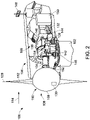
- Fig. 2 is a partial sectional view of nacelle 106 used with wind turbine 100.
- various components of wind turbine 100 are housed in nacelle 106.
- nacelle 106 includes pitch assemblies 130.
- rotor 108 is rotatably coupled to an electrical machine 132, for example a generator, positioned within nacelle 106 via a rotor shaft 134 (sometimes referred to as either a main shaft or a low speed shaft), a gearbox 136, a high speed shaft 138, and a coupling 140. Rotation of rotor shaft 134 rotatably drives gearbox 136 that subsequently drives high speed shaft 138.
- High speed shaft 138 rotatably drives generator 132 via coupling 140 and rotation of high speed shaft 138 facilitates production of electrical power by generator 132.
- Gearbox 136 is supported by a support 142 and generator 132 is supported by a support 144.
- gearbox 136 uses a dual path geometry to drive high speed shaft 138.
- rotor shaft 134 may be coupled directly to generator 132 via coupling 140.
- Nacelle 106 also includes a yaw drive mechanism 146 that rotates nacelle 106 and rotor 108 about yaw axis 116 to control the perspective of rotor blades 112 with respect to the direction of wind 114.
- Nacelle 106 also includes at least one meteorological mast 148 that, in one embodiment, includes a wind vane and anemometer (neither shown in Fig. 2 ).
- meteorological mast 148 provides information, including wind direction and/or wind speed, to a turbine control system 150.
- Turbine control system 150 includes one or more controllers or other processors configured to execute control algorithms.
- processor includes any programmable system including systems and microcontrollers, reduced instruction set circuits (RISC), application specific integrated circuits (ASIC), programmable logic circuits (PLC), and any other circuit capable of executing the functions described herein.
- RISC reduced instruction set circuits
- ASIC application specific integrated circuits
- PLC programmable logic circuits
- SCADA Supervisory, Control and Data Acquisition
- nacelle 106 also includes forward support bearing 152 and aft support bearing 154.
- Forward support bearing 152 and aft support bearing 154 facilitate radial support and alignment of rotor shaft 134.
- Forward support bearing 152 is coupled to rotor shaft 134 near hub 110.
- Aft support bearing 154 is positioned on rotor shaft 134 near gearbox 136 and/or generator 132.
- Nacelle 106 may include any number of support bearings that enable wind turbine 100 to function as disclosed herein.
- Fig. 3 is a perspective view of rotor 108 which includes hub 110, blades 112 and a dome 158 (portions removed for illustrative purposes).
- Hub 110 is coupled to shaft 134 and dome 158 is coupled to hub 110.
- hub 110 includes a space frame structure 160 which has a truss-like, lightweight rigid configuration formed by interlocking struts 162 in a geometric pattern 164.
- Space frame structure 160 can include any configuration and/or pattern to enable rotor 108 to function as described herein.
- Space frame structure 160 is configured to support the plurality of blades 112 away from shaft 134 while minimizing blade length and/or blade mass.
- Fig. 4 illustrates a perspective view of hub 110 which includes a central portion 166 and a plurality of structural members 168 coupled to central portion 166.
- Central portion 166 is coupled to shaft 134 and includes a plurality of strut members 170.
- strut members 170 are configured in a space frame configuration having a polyhedron shape 172. More particularly, strut members 170 can be configured in a tetrahedron shape or a square-pyramid shape.
- Strut members 170 can include any shape to enable central portion 166 to function as described herein.
- Strut members 170 are configured to provide a lightweight and rigid configuration for supporting structural members 168.
- Strut members 170 include materials such as, but not limited to, metals, plastics, alloys, composites and combinations thereof.
- strut members 170 can include damping elements (not shown) such as, for example, shock absorbers and damping coatings.
- Structural members 168 are coupled to central portion 166 and are configured to radially extend therefrom. In the exemplary embodiment, structural members 168 are radially coupled to central portion 166 and are orientated about 60% from each other. Alternatively, structural members 168 can extend from central portion 166 at any angular relationship. Structural members 168 include a first member 174, a second member 176 and a third member 178. Structural members 168 may include more than three members or less than three members to enable rotor 108 to function as described herein. Each first member 174, second member 176 and third member178 includes a first end 180 and a second end 182. Second end 182 includes a pitch bearing support ring 184 which is configured to couple to pitch assembly 130 (shown in Fig. 2 ).
- First member 174, second member 176 and third member 178 include a plurality of primary members 186 coupled to first end 180 and second end 182. Each first member174, second member 176 and third member 178 further includes a plurality of secondary members 188 coupled to the plurality of primary members 186. Primary and secondary members 186 and 188 are configured to provide a lightweight and rigid configuration for supporting blades 112. Moreover, each structural member 168 includes a cross strut member 190 coupled to primary members 186 and secondary members 188. Cross strut member 190 is configured to facilitate tensioning primary member and secondary members 186 and 188. In one embodiment, structural members 168 are aerodynamically shaped to receive wind 114 (shown in Fig. 1 ) to facilitate rotating shaft 134. More particularly, structural members 168 can include blades and/or vanes (not shown) to receive wind 114 to facilitate rotating shaft 134.
- primary members 186 are configured in a space frame configuration having a polyhedron shape 172.
- secondary members 188 are configured in a space frame configuration having polyhedron shape 172.
- primary members and secondary members 186 and 188 can include any shape to enable structural members 168 to function as described herein.
- primary and secondary members 186 and 188 include materials such as, but not limited to, metals, plastics, alloys, composites and combinations thereof.
- Primary and second members 186 and 188 can include damping elements (not shown) such as, but not limited to, shock absorbers and damping coatings.
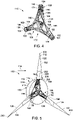
- Fig. 5 is another perspective view of hub 110, blades 112 and dome 158.
- blades 112 are coupled to the plurality of structural members 168. More particularly, blades 112 includes a first blade 192 coupled to first member 174, a second blade 194 coupled to second member 176 and a third blade 196 coupled to third member 178. Blades 112 may include more than three blades 112 or less than three blades 112. Blades 112 may include any number of blades 112 to enable rotor 108 to function as described herein.
- First blade 192, second blade 194 and third blade 196 include a root end 198, a tip end 200 and blade surface 126 between root end 198 and tip end 200.
- Root end 198 is coupled to second end portion 182 of each portion 168 and spaced away from shaft 134.
- Each blade 192, 194, and 196 further includes an aerodynamic fairing 202 coupled to root end 198.
- Fairing 202 is configured to receive wind 114 to facilitate rotating shaft 134, wherein each fairing 202 includes an outer surface 204 and an inner surface 206.
- Outer surface 204 is configured to receive wind 114 to increase aerodynamic lift to facilitate rotating shaft 134.
- Inner surface 206 defines a void 208 between outer surface 204 and root end 198, wherein void 208 is configured to reduce weight of fairing 202.
- Dome 158 is coupled to at least one of first member 174, second member 176 and third member 178.
- dome 158 is semi-circular shaped and configured to direct wind 114 toward fairings 202 to facilitate rotating shaft 134.
- dome 158 can include other aerodynamic shapes, such as, for example, blades and vanes.
- Dome 158 can include any shape to enable rotor 108 to function as described herein.
- Dome 158 includes an outer surface 210 and an inner surface 212, wherein inner surface 212 is coupled to second end 182.
- Inner surface 216 is positioned adjacent to fairings 202 to facilitate minimizing and/or eliminating air gaps between dome 158 and fairings 202 to maximize directing wind 114 toward fairings 202.
- Fig. 6 illustrates a cross sectional view of hub 110 and blade 112.
- Pitch assembly 130 is coupled to each blade 112 and each structural members 168, wherein each pitch assembly 130 is configured to modulate a pitch of associated blade 112 about pitch axis 128.
- pitch assembly 130 is coupled to bearing support ring 184 of each second end 182.
- Pitch assembly 130 includes a pitch motor 214 and a bearing 216, wherein a tube spar 218 of each blade 112 is coupled to a bearing housing 217.
- a pitch angle (not shown) of blades 112 may be changed by pitch assembly 130. More specifically, increasing a pitch angle of blade 112 decreases an amount of blade surface area 126 exposed to wind 114 and, conversely, decreasing a pitch angle of blade 112 increases an amount of blade surface area 126 exposed to wind 114.
- the pitch angles of blades 112 are adjusted about pitch axis 128 at each blade 112. In the exemplary embodiment, the pitch angles of blades 112 are controlled individually. Alternatively, the pitch angles of blades 112 can be controlled in groups.
- Each structural member 168 has a first length L1 as measured from second end 182 to shaft 134. Moreover, each blade 112 is spaced from shaft 134 at a second length L2 as measured from tip end 200 to shaft 134.
- First length L1 is different than second length L2. In the exemplary embodiment, first length L1 is shorter than second length L2. More particularly, first length L1 is about 10% to about 50% of second length L2. In one embodiment, first length L1 is about 20% of second length L2.
- First and second lengths L2 are sized to facilitate maximizing aerodynamic lift of blades 112 and minimizing blade length and/or blade mass. Moreover, first and second lengths L1 and L2 are sized to minimize blade bending moments and blade tip deflections. Alternatively, first length L1 can be about the same as or longer than second length L2.
- First and second lengths L1 and L2 can include any size that enables rotor 108 to function as described herein.
- Central portion 166 structural members 168 of hub 110 are sized and shaped to increase strength of rotor 108 via primary and secondary members 186 and 188 between blade root ends 198 and shaft 134 to increase efficiency of rotor 108.
- Central portion 166 and structural members 168 are configured to minimize bending moments at root ends 198 by up to 50% as compared to conventional, cantilevered blades (not shown).
- central portion 166 and structural members 168 are configured to minimize deflection of blade tip ends 200 by up to about 50% as compared to conventional, cantilevered blades. More particularly, central portion 166 and structural members 168 are configured to reduce bending moments at root ends 198 by up to about 30% and deflection of tip ends 200 by up to about 40% as compared to conventional, cantilevered blades.
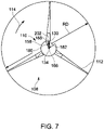
- Fig. 7 is a front view of rotor 108 shown in Fig. 3 . Since central portion 166 and structural members 168 are configured to extend outward from shaft 134 and support blades 112 away from shaft 134, blade length can be reduced as compared to conventional blades. Moreover, a reduced blade length results in a lighter and less expensive blade to manufacture due to less material. In the exemplary embodiment, portion first length L1 (shown in Fig. 6 ) is about 20% of second length L2 (shown in Fig. 6 ) to facilitate reducing blade length. Reduced blade length results in a lighter and less expensive pitch assembly 130 needed due to lesser loads applied by blades 112 to pitch assembly 130, and in particular, pitch assembly bearing 216.
- pitch assembly 130 is coupled to second end 182 where blade bending moments are up to about 50% less as compared to blade bending moments at first end 180. Since pitch assembly 130 is coupled to second end 182 and experiences less bending moments, pitch assembly 130 is lighter and less expensive.
- Second length L2 reduces material cost, manufacturing cost, transportation costs and/or installation costs for blades 112 while reducing up-tower mass.
- rotor diameter RD is substantially the same as compared to conventional rotor diameters (not shown) while rotor 108 includes reduced sized blades 112.
- rotor diameter RD can be increased by using conventional blades (not shown) since space frame hub 110 extends blades 112 beyond shaft 134.
- dome 158 is sized from about 10% to about 30% of rotor diameter RD. More particularly, dome 158 is sized up to about 20% of rotor diameter RD.
- Dome 158 can be any size to enable rotor 108 to function as described herein. Dome 158 is sized and shaped to direct wind 114 toward fairing 202. Alternatively, dome 158 can be removed to expose aerodynamically shaped portions 168 which are configured to receive wind 114 to facilitate rotating shaft 134.
- Fig. 8 illustrates an exemplary flowchart illustrating a method 800 of assembling a rotor, for example rotor 108 (shown in Fig. 3 ).
- Method 800 includes forming 802 a space frame central portion, for example central portion 166 (shown in Fig. 4 ), from a plurality of struts, such as struts 170 (shown in Fig. 4 ).
- the space frame portion is formed into a polyhedron shape, for example polyhedron shape 162 (shown in Fig. 3 ).
- a space frame portion, such as space frame portion 168 (shown in Fig. 4 ) is also formed 804 from a plurality of members, for example members 186 and 188 (shown in Fig.
- the space frame portion includes a first member, a second member and a third member, for example first member 174, second member 176 and third member 178 (shown in Fig. 4 ).
- the space frame portion is coupled 806 to the space frame central portion.
- Method 800 includes coupling 808 a pitch assembly, for example pitch assembly 130 (shown in Fig. 6 ), to each member.
- Method 800 includes coupling 810 a blade, such as blade 112 (shown in Fig. 3 ), to the space frame portion.
- Blade includes a first blade, a second blade and a third blade, for example first blade 192, second blade 194 and third blade 196 (shown in Fig. 3 ), which are coupled to the first member, the second member and the third member respectively.
- the blade is coupled 812 to the pitch assembly.
- method 800 includes coupling 814 an aerodynamic fairing, for example fairing 202 (shown in Fig. 3 ), to the blade. More particularly, fairing is coupled to a root end, for example root end 198 (shown in Fig. 3 ), of the blade. Moreover, method 800 includes coupling 816 a dome, such as dome 158 (shown in Fig. 5 ), to the space frame portion. More particularly, dome is coupled to a second end, for example, second end 182 (shown in Fig. 3 ). Method 800 further includes coupling 818 the central portion to a shaft, for example shaft 134 (shown in Fig. 5 ).
- an aerodynamic fairing for example fairing 202 (shown in Fig. 3 )
- fairing is coupled to a root end, for example root end 198 (shown in Fig. 3 ), of the blade.
- method 800 includes coupling 816 a dome, such as dome 158 (shown in Fig. 5 ), to the space frame portion. More particularly, dome
- the embodiments described herein relate to a rotor configured to enhance aerodynamic efficiency of a wind turbine to increase higher energy conversion.
- the embodiments described herein reduce manufacturing costs, transportation costs and/or installation costs.
- the embodiments described herein reduce blade bending moments and/or blade tip deflection and/or loads applied to turbine components such as pitch assemblies and yaw assemblies.
- a technical effect of the systems and methods described herein includes at least one of: a rotor having a space frame hub having a central portion coupled to the shaft and a first member, a second member, and a third member coupled to the central portion, wherein the first member, the second member, and third member each has a first length; and a first blade coupled to the first member, a second blade coupled to the second member, and third blade coupled to the third member and each having a second length that is longer than the first length.
- Exemplary embodiments of a rotor and methods for assembling the rotor are described above in detail.
- the methods and systems are not limited to the specific embodiments described herein, but rather, components of systems and/or steps of the methods may be utilized independently and separately from other components and/or steps described herein.
- the methods may also be used in combination with other manufacturing systems and methods, and are not limited to practice with only the systems and methods as described herein. Rather, the exemplary embodiment can be implemented and utilized in connection with many other electrical component applications.
Landscapes
- Engineering & Computer Science (AREA)
- Life Sciences & Earth Sciences (AREA)
- Sustainable Development (AREA)
- Sustainable Energy (AREA)
- Chemical & Material Sciences (AREA)
- Combustion & Propulsion (AREA)
- Mechanical Engineering (AREA)
- General Engineering & Computer Science (AREA)
- Physics & Mathematics (AREA)
- Fluid Mechanics (AREA)
- Wind Motors (AREA)
Claims (10)
- Rotor (108) accouplé à un arbre rotatif (134), ledit rotor (108) comprenant :un moyeu de structure spatiale (110) comprenant une partie centrale (166) accouplée à l'arbre rotatif (134) et un premier élément structural (174), un deuxième élément structural (176) et un troisième élément structural (178) accouplés à ladite partie centrale (166), chacun desdits premier, deuxième et troisième éléments structuraux (174, 176, 178) ayant une première longueur où chacun desdits premier, deuxième et troisième éléments structuraux (174, 176, 178) comprend une pluralité d'éléments primaires d'emboîtement (186) et une pluralité d'éléments secondaires d'emboîtement (188), etune première pale (192) accouplée audit premier élément structural (174), une deuxième pale (194) accouplée audit deuxième élément structural (176) et une troisième pale (196) accouplée audit troisième élément structural (178) et ayant chacune une extrémité de pointe espacée de l'arbre (134) au niveau d'une seconde longueur qui est supérieure à ladite première longueur.
- Rotor (108) selon la revendication 1, dans lequel ladite partie centrale (166) comprend une pluralité d'éléments d'entretoise d'emboîtement (170) en forme de polyèdre.
- Rotor (108) selon l'une quelconque des revendications précédentes, dans lequel les éléments d'entretoise (170) sont en forme de tétraèdre
- Rotor (108) selon l'une quelconque des revendications précédentes, dans lequel le premier élément structural (174), le deuxième élément structural (176) et le troisième élément structural (178) du rotor (108) sont de forme aérodynamique.
- Rotor (108) selon l'une quelconque des revendications précédentes, dans lequel ladite première longueur est d'environ 10 % à environ 40 % de ladite seconde longueur.
- Rotor (108) selon l'une quelconque des revendications précédentes, dans lequel lesdites première pale (192), deuxième pale (194) et troisième pale (196) comprennent chacune un carénage aérodynamique.
- Rotor (108) selon l'une quelconque des revendications précédentes, comprenant en outre un dôme semi-circulaire (158) accouplé auxdits premier élément structural (174), deuxième élément structural (176) et troisième élément structural (178).
- Rotor (108) selon l'une quelconque des revendications précédentes, comprenant en outre un premier ensemble de pas (130) accouplé audit premier élément structural (174) et à ladite première pale (192), un deuxième ensemble de pas (130) accouplé audit deuxième élément structural (176) et à ladite deuxième pale (194) et un troisième ensemble de pas (130) accouplé audit troisième élément structural (176) et à ladite troisième pale (196).
- Éolienne (100), comprenant :un mât (102) ;une nacelle (106) accouplée audit mât (102) ;un arbre (134) accouplé à ladite nacelle (106) ; etun rotor (108) selon l'une quelconque des revendications précédentes accouplé audit mât (102).
- Procédé d'assemblage d'un rotor (108) selon l'une quelconque des revendications précédentes à un arbre (134), ledit procédé étant caractérisé en ce qu'il comprend :l'accouplement radial d'une partie de structure spatiale à une partie centrale (806) de structure spatiale ;l'accouplement d'un ensemble de pas à la partie de structure spatiale (808) ;l'accouplement d'une pale à la partie de structure spatiale et à l'ensemble de pas (810) ; etl'accouplement de la partie centrale de structure spatiale à l'arbre (818).
Applications Claiming Priority (2)
| Application Number | Priority Date | Filing Date | Title |
|---|---|---|---|
| US13/683,734 US9249777B2 (en) | 2012-11-21 | 2012-11-21 | Wind turbine rotor and methods of assembling the same |
| PCT/US2013/070883 WO2014081754A1 (fr) | 2012-11-21 | 2013-11-20 | Rotor de turbine éolienne et ses procédés d'assemblage |
Publications (2)
| Publication Number | Publication Date |
|---|---|
| EP2923077A1 EP2923077A1 (fr) | 2015-09-30 |
| EP2923077B1 true EP2923077B1 (fr) | 2023-01-11 |
Family
ID=49724678
Family Applications (1)
| Application Number | Title | Priority Date | Filing Date |
|---|---|---|---|
| EP13801942.7A Active EP2923077B1 (fr) | 2012-11-21 | 2013-11-20 | Rotor de turbine éolienne et ses procédés d'assemblage |
Country Status (6)
| Country | Link |
|---|---|
| US (1) | US9249777B2 (fr) |
| EP (1) | EP2923077B1 (fr) |
| CA (1) | CA2892050C (fr) |
| DK (1) | DK2923077T3 (fr) |
| ES (1) | ES2942175T3 (fr) |
| WO (1) | WO2014081754A1 (fr) |
Families Citing this family (5)
| Publication number | Priority date | Publication date | Assignee | Title |
|---|---|---|---|---|
| WO2014161607A1 (fr) * | 2013-04-03 | 2014-10-09 | Aktiebolaget Skf | Moyeu, système d'appui et turbine comprenant le moyeu et le système d'appui |
| US9249776B2 (en) * | 2014-02-19 | 2016-02-02 | General Electric Company | Wind turbine dome and method of assembly |
| GB201420833D0 (en) * | 2014-11-24 | 2015-01-07 | Blade Dynamics Ltd | A hub for a wind turbine |
| WO2016156623A1 (fr) * | 2015-03-31 | 2016-10-06 | Nabrawind Sl | Nouveau moyeu d'un aérogénérateur |
| US10507902B2 (en) * | 2015-04-21 | 2019-12-17 | General Electric Company | Wind turbine dome and method of assembly |
Family Cites Families (15)
| Publication number | Priority date | Publication date | Assignee | Title |
|---|---|---|---|---|
| ZA816875B (en) | 1980-10-07 | 1982-11-24 | Sir Mcalpine R & Sons Ltd | Wind powered turbine |
| US4735552A (en) | 1985-10-04 | 1988-04-05 | Watson William K | Space frame wind turbine |
| US6951443B1 (en) | 2000-09-08 | 2005-10-04 | General Electric Company | Wind turbine ring/shroud drive system |
| JP2005282451A (ja) | 2004-03-30 | 2005-10-13 | Ishikawajima Harima Heavy Ind Co Ltd | 風力発電装置 |
| CA2467199A1 (fr) | 2004-05-19 | 2005-11-19 | Bud T.J. Johnson | Eolienne |
| US7740450B2 (en) | 2005-11-23 | 2010-06-22 | General Electric Company | Lightweight hub for rotors |
| GB0609799D0 (en) * | 2006-05-18 | 2006-06-28 | Euro Projects Ltd | A turbine blade support assembly |
| US7713028B2 (en) | 2006-11-27 | 2010-05-11 | Ning Liao | Turbine blade assembly |
| US8092182B2 (en) | 2007-09-14 | 2012-01-10 | Theodore Radisek | Wind turbine blade support structure |
| US20090148291A1 (en) * | 2007-12-06 | 2009-06-11 | General Electric Company | Multi-section wind turbine rotor blades and wind turbines incorporating same |
| GB0818610D0 (en) | 2008-10-10 | 2008-11-19 | Sway As | Wind turbine rotor and wind turbine |
| US8142164B2 (en) | 2009-12-31 | 2012-03-27 | General Electric Company | Rotor blade for use with a wind turbine and method for assembling rotor blade |
| GB201006477D0 (en) | 2010-04-19 | 2010-06-02 | Wesby Philip | System and method for a vertical axis wind turbine |
| US7939961B1 (en) | 2010-04-28 | 2011-05-10 | General Electric Company | Wind turbine with integrated design and controlling method |
| US8123478B2 (en) | 2010-05-26 | 2012-02-28 | General Electric Company | Systems and methods for monitoring a condition of a rotor blade for a wind turbine |
-
2012
- 2012-11-21 US US13/683,734 patent/US9249777B2/en active Active
-
2013
- 2013-11-20 EP EP13801942.7A patent/EP2923077B1/fr active Active
- 2013-11-20 WO PCT/US2013/070883 patent/WO2014081754A1/fr active Application Filing
- 2013-11-20 ES ES13801942T patent/ES2942175T3/es active Active
- 2013-11-20 DK DK13801942.7T patent/DK2923077T3/da active
- 2013-11-20 CA CA2892050A patent/CA2892050C/fr active Active
Also Published As
| Publication number | Publication date |
|---|---|
| CA2892050A1 (fr) | 2014-05-30 |
| CA2892050C (fr) | 2017-03-14 |
| EP2923077A1 (fr) | 2015-09-30 |
| WO2014081754A1 (fr) | 2014-05-30 |
| US9249777B2 (en) | 2016-02-02 |
| ES2942175T3 (es) | 2023-05-30 |
| US20140140851A1 (en) | 2014-05-22 |
| DK2923077T3 (da) | 2023-04-03 |
Similar Documents
| Publication | Publication Date | Title |
|---|---|---|
| US7802968B2 (en) | Methods and apparatus for reducing load in a rotor blade | |
| US20090148285A1 (en) | Multi-section wind turbine rotor blades and wind turbines incorporating same | |
| US8303250B2 (en) | Method and apparatus for increasing lift on wind turbine blade | |
| US7939961B1 (en) | Wind turbine with integrated design and controlling method | |
| EP1861619B1 (fr) | Roue de tension dans un systeme de rotor pour turbines hydrauliques et eoliennes | |
| US9239040B2 (en) | Root end assembly configuration for a wind turbine rotor blade and associated forming methods | |
| EP2821635B1 (fr) | Ensemble de moyeu aérodynamique pour une turbine éolienne | |
| EP2194267B1 (fr) | Manche pour le pied d'une pale d'éolienne | |
| EP2923077B1 (fr) | Rotor de turbine éolienne et ses procédés d'assemblage | |
| CN101451493A (zh) | 多段式风力涡轮机转子叶片和包括该叶片的风力涡轮机 | |
| US20100111697A1 (en) | Wind energy generation device | |
| US20070205603A1 (en) | Methods and devices for improving efficiency of wind turbines in low wind speed sites | |
| EP2436924A1 (fr) | Appareil pour une éolienne | |
| US20120328443A1 (en) | Systems and methods for assembling a wind turbine with a pitch assembly | |
| EP3473851A1 (fr) | Générateur de turbine éolienne | |
| US8562300B2 (en) | Wind turbine with high solidity rotor | |
| EP2863052B1 (fr) | Rotor de turbine éolienne et éolienne | |
| JP2012092651A (ja) | 風力発電装置 | |
| US8148841B1 (en) | Modular wind turbine system | |
| EP2447523B1 (fr) | Éolienne | |
| CN202165212U (zh) | 一种垂直轴风力发电机风轮结构 | |
| EP3396153A1 (fr) | Une combinaison d'une turbine à jet de vent et d'une éolienne | |
| KR101990381B1 (ko) | 양력과 항력 보완식 수평축 풍력발전기 | |
| KR101042906B1 (ko) | 풍력발전기용 로터 | |
| JP6887933B2 (ja) | 風力発電装置 |
Legal Events
| Date | Code | Title | Description |
|---|---|---|---|
| PUAI | Public reference made under article 153(3) epc to a published international application that has entered the european phase |
Free format text: ORIGINAL CODE: 0009012 |
|
| 17P | Request for examination filed |
Effective date: 20150622 |
|
| AK | Designated contracting states |
Kind code of ref document: A1 Designated state(s): AL AT BE BG CH CY CZ DE DK EE ES FI FR GB GR HR HU IE IS IT LI LT LU LV MC MK MT NL NO PL PT RO RS SE SI SK SM TR |
|
| AX | Request for extension of the european patent |
Extension state: BA ME |
|
| DAX | Request for extension of the european patent (deleted) | ||
| STAA | Information on the status of an ep patent application or granted ep patent |
Free format text: STATUS: EXAMINATION IS IN PROGRESS |
|
| 17Q | First examination report despatched |
Effective date: 20180309 |
|
| STAA | Information on the status of an ep patent application or granted ep patent |
Free format text: STATUS: EXAMINATION IS IN PROGRESS |
|
| STAA | Information on the status of an ep patent application or granted ep patent |
Free format text: STATUS: EXAMINATION IS IN PROGRESS |
|
| GRAP | Despatch of communication of intention to grant a patent |
Free format text: ORIGINAL CODE: EPIDOSNIGR1 |
|
| STAA | Information on the status of an ep patent application or granted ep patent |
Free format text: STATUS: GRANT OF PATENT IS INTENDED |
|
| INTG | Intention to grant announced |
Effective date: 20220413 |
|
| GRAJ | Information related to disapproval of communication of intention to grant by the applicant or resumption of examination proceedings by the epo deleted |
Free format text: ORIGINAL CODE: EPIDOSDIGR1 |
|
| STAA | Information on the status of an ep patent application or granted ep patent |
Free format text: STATUS: EXAMINATION IS IN PROGRESS |
|
| INTC | Intention to grant announced (deleted) | ||
| GRAP | Despatch of communication of intention to grant a patent |
Free format text: ORIGINAL CODE: EPIDOSNIGR1 |
|
| STAA | Information on the status of an ep patent application or granted ep patent |
Free format text: STATUS: GRANT OF PATENT IS INTENDED |
|
| INTG | Intention to grant announced |
Effective date: 20220902 |
|
| GRAS | Grant fee paid |
Free format text: ORIGINAL CODE: EPIDOSNIGR3 |
|
| GRAA | (expected) grant |
Free format text: ORIGINAL CODE: 0009210 |
|
| STAA | Information on the status of an ep patent application or granted ep patent |
Free format text: STATUS: THE PATENT HAS BEEN GRANTED |
|
| AK | Designated contracting states |
Kind code of ref document: B1 Designated state(s): AL AT BE BG CH CY CZ DE DK EE ES FI FR GB GR HR HU IE IS IT LI LT LU LV MC MK MT NL NO PL PT RO RS SE SI SK SM TR |
|
| REG | Reference to a national code |
Ref country code: GB Ref legal event code: FG4D |
|
| REG | Reference to a national code |
Ref country code: CH Ref legal event code: EP |
|
| REG | Reference to a national code |
Ref country code: DE Ref legal event code: R096 Ref document number: 602013083215 Country of ref document: DE |
|
| REG | Reference to a national code |
Ref country code: IE Ref legal event code: FG4D |
|
| REG | Reference to a national code |
Ref country code: AT Ref legal event code: REF Ref document number: 1543565 Country of ref document: AT Kind code of ref document: T Effective date: 20230215 |
|
| REG | Reference to a national code |
Ref country code: DK Ref legal event code: T3 Effective date: 20230331 |
|
| REG | Reference to a national code |
Ref country code: LT Ref legal event code: MG9D |
|
| REG | Reference to a national code |
Ref country code: NL Ref legal event code: MP Effective date: 20230111 |
|
| REG | Reference to a national code |
Ref country code: ES Ref legal event code: FG2A Ref document number: 2942175 Country of ref document: ES Kind code of ref document: T3 Effective date: 20230530 |
|
| REG | Reference to a national code |
Ref country code: AT Ref legal event code: MK05 Ref document number: 1543565 Country of ref document: AT Kind code of ref document: T Effective date: 20230111 |
|
| PG25 | Lapsed in a contracting state [announced via postgrant information from national office to epo] |
Ref country code: NL Free format text: LAPSE BECAUSE OF FAILURE TO SUBMIT A TRANSLATION OF THE DESCRIPTION OR TO PAY THE FEE WITHIN THE PRESCRIBED TIME-LIMIT Effective date: 20230111 |
|
| P01 | Opt-out of the competence of the unified patent court (upc) registered |
Effective date: 20230530 |
|
| PG25 | Lapsed in a contracting state [announced via postgrant information from national office to epo] |
Ref country code: RS Free format text: LAPSE BECAUSE OF FAILURE TO SUBMIT A TRANSLATION OF THE DESCRIPTION OR TO PAY THE FEE WITHIN THE PRESCRIBED TIME-LIMIT Effective date: 20230111 Ref country code: PT Free format text: LAPSE BECAUSE OF FAILURE TO SUBMIT A TRANSLATION OF THE DESCRIPTION OR TO PAY THE FEE WITHIN THE PRESCRIBED TIME-LIMIT Effective date: 20230511 Ref country code: NO Free format text: LAPSE BECAUSE OF FAILURE TO SUBMIT A TRANSLATION OF THE DESCRIPTION OR TO PAY THE FEE WITHIN THE PRESCRIBED TIME-LIMIT Effective date: 20230411 Ref country code: LV Free format text: LAPSE BECAUSE OF FAILURE TO SUBMIT A TRANSLATION OF THE DESCRIPTION OR TO PAY THE FEE WITHIN THE PRESCRIBED TIME-LIMIT Effective date: 20230111 Ref country code: LT Free format text: LAPSE BECAUSE OF FAILURE TO SUBMIT A TRANSLATION OF THE DESCRIPTION OR TO PAY THE FEE WITHIN THE PRESCRIBED TIME-LIMIT Effective date: 20230111 Ref country code: HR Free format text: LAPSE BECAUSE OF FAILURE TO SUBMIT A TRANSLATION OF THE DESCRIPTION OR TO PAY THE FEE WITHIN THE PRESCRIBED TIME-LIMIT Effective date: 20230111 Ref country code: AT Free format text: LAPSE BECAUSE OF FAILURE TO SUBMIT A TRANSLATION OF THE DESCRIPTION OR TO PAY THE FEE WITHIN THE PRESCRIBED TIME-LIMIT Effective date: 20230111 |
|
| PG25 | Lapsed in a contracting state [announced via postgrant information from national office to epo] |
Ref country code: SE Free format text: LAPSE BECAUSE OF FAILURE TO SUBMIT A TRANSLATION OF THE DESCRIPTION OR TO PAY THE FEE WITHIN THE PRESCRIBED TIME-LIMIT Effective date: 20230111 Ref country code: PL Free format text: LAPSE BECAUSE OF FAILURE TO SUBMIT A TRANSLATION OF THE DESCRIPTION OR TO PAY THE FEE WITHIN THE PRESCRIBED TIME-LIMIT Effective date: 20230111 Ref country code: IS Free format text: LAPSE BECAUSE OF FAILURE TO SUBMIT A TRANSLATION OF THE DESCRIPTION OR TO PAY THE FEE WITHIN THE PRESCRIBED TIME-LIMIT Effective date: 20230511 Ref country code: GR Free format text: LAPSE BECAUSE OF FAILURE TO SUBMIT A TRANSLATION OF THE DESCRIPTION OR TO PAY THE FEE WITHIN THE PRESCRIBED TIME-LIMIT Effective date: 20230412 Ref country code: FI Free format text: LAPSE BECAUSE OF FAILURE TO SUBMIT A TRANSLATION OF THE DESCRIPTION OR TO PAY THE FEE WITHIN THE PRESCRIBED TIME-LIMIT Effective date: 20230111 |
|
| REG | Reference to a national code |
Ref country code: DE Ref legal event code: R097 Ref document number: 602013083215 Country of ref document: DE |
|
| PG25 | Lapsed in a contracting state [announced via postgrant information from national office to epo] |
Ref country code: SM Free format text: LAPSE BECAUSE OF FAILURE TO SUBMIT A TRANSLATION OF THE DESCRIPTION OR TO PAY THE FEE WITHIN THE PRESCRIBED TIME-LIMIT Effective date: 20230111 Ref country code: RO Free format text: LAPSE BECAUSE OF FAILURE TO SUBMIT A TRANSLATION OF THE DESCRIPTION OR TO PAY THE FEE WITHIN THE PRESCRIBED TIME-LIMIT Effective date: 20230111 Ref country code: EE Free format text: LAPSE BECAUSE OF FAILURE TO SUBMIT A TRANSLATION OF THE DESCRIPTION OR TO PAY THE FEE WITHIN THE PRESCRIBED TIME-LIMIT Effective date: 20230111 Ref country code: CZ Free format text: LAPSE BECAUSE OF FAILURE TO SUBMIT A TRANSLATION OF THE DESCRIPTION OR TO PAY THE FEE WITHIN THE PRESCRIBED TIME-LIMIT Effective date: 20230111 |
|
| PLBE | No opposition filed within time limit |
Free format text: ORIGINAL CODE: 0009261 |
|
| STAA | Information on the status of an ep patent application or granted ep patent |
Free format text: STATUS: NO OPPOSITION FILED WITHIN TIME LIMIT |
|
| PG25 | Lapsed in a contracting state [announced via postgrant information from national office to epo] |
Ref country code: SK Free format text: LAPSE BECAUSE OF FAILURE TO SUBMIT A TRANSLATION OF THE DESCRIPTION OR TO PAY THE FEE WITHIN THE PRESCRIBED TIME-LIMIT Effective date: 20230111 |
|
| REG | Reference to a national code |
Ref country code: DE Ref legal event code: R082 Ref document number: 602013083215 Country of ref document: DE Representative=s name: ZIMMERMANN & PARTNER PATENTANWAELTE MBB, DE Ref country code: DE Ref legal event code: R082 Ref document number: 602013083215 Country of ref document: DE Ref country code: DE Ref legal event code: R081 Ref document number: 602013083215 Country of ref document: DE Owner name: GENERAL ELECTRIC RENOVABLES ESPANA, S.L., ES Free format text: FORMER OWNER: GENERAL ELECTRIC COMPANY, SCHENECTADY, NY, US |
|
| 26N | No opposition filed |
Effective date: 20231012 |
|
| PGFP | Annual fee paid to national office [announced via postgrant information from national office to epo] |
Ref country code: ES Payment date: 20231201 Year of fee payment: 11 |
|
| PG25 | Lapsed in a contracting state [announced via postgrant information from national office to epo] |
Ref country code: SI Free format text: LAPSE BECAUSE OF FAILURE TO SUBMIT A TRANSLATION OF THE DESCRIPTION OR TO PAY THE FEE WITHIN THE PRESCRIBED TIME-LIMIT Effective date: 20230111 |
|
| PGFP | Annual fee paid to national office [announced via postgrant information from national office to epo] |
Ref country code: DK Payment date: 20231019 Year of fee payment: 11 Ref country code: DE Payment date: 20231019 Year of fee payment: 11 |
|
| REG | Reference to a national code |
Ref country code: DE Ref legal event code: R082 Ref document number: 602013083215 Country of ref document: DE Representative=s name: ZIMMERMANN & PARTNER PATENTANWAELTE MBB, DE |