EP3396153A1 - Une combinaison d'une turbine à jet de vent et d'une éolienne - Google Patents
Une combinaison d'une turbine à jet de vent et d'une éolienne Download PDFInfo
- Publication number
- EP3396153A1 EP3396153A1 EP17167730.5A EP17167730A EP3396153A1 EP 3396153 A1 EP3396153 A1 EP 3396153A1 EP 17167730 A EP17167730 A EP 17167730A EP 3396153 A1 EP3396153 A1 EP 3396153A1
- Authority
- EP
- European Patent Office
- Prior art keywords
- wind
- wind turbine
- turbine
- rotor
- hub
- Prior art date
- Legal status (The legal status is an assumption and is not a legal conclusion. Google has not performed a legal analysis and makes no representation as to the accuracy of the status listed.)
- Withdrawn
Links
Images


Classifications
-
- F—MECHANICAL ENGINEERING; LIGHTING; HEATING; WEAPONS; BLASTING
- F03—MACHINES OR ENGINES FOR LIQUIDS; WIND, SPRING, OR WEIGHT MOTORS; PRODUCING MECHANICAL POWER OR A REACTIVE PROPULSIVE THRUST, NOT OTHERWISE PROVIDED FOR
- F03D—WIND MOTORS
- F03D9/00—Adaptations of wind motors for special use; Combinations of wind motors with apparatus driven thereby; Wind motors specially adapted for installation in particular locations
- F03D9/20—Wind motors characterised by the driven apparatus
- F03D9/25—Wind motors characterised by the driven apparatus the apparatus being an electrical generator
-
- F—MECHANICAL ENGINEERING; LIGHTING; HEATING; WEAPONS; BLASTING
- F03—MACHINES OR ENGINES FOR LIQUIDS; WIND, SPRING, OR WEIGHT MOTORS; PRODUCING MECHANICAL POWER OR A REACTIVE PROPULSIVE THRUST, NOT OTHERWISE PROVIDED FOR
- F03D—WIND MOTORS
- F03D1/00—Wind motors with rotation axis substantially parallel to the air flow entering the rotor
- F03D1/02—Wind motors with rotation axis substantially parallel to the air flow entering the rotor having a plurality of rotors
- F03D1/025—Wind motors with rotation axis substantially parallel to the air flow entering the rotor having a plurality of rotors coaxially arranged
-
- F—MECHANICAL ENGINEERING; LIGHTING; HEATING; WEAPONS; BLASTING
- F03—MACHINES OR ENGINES FOR LIQUIDS; WIND, SPRING, OR WEIGHT MOTORS; PRODUCING MECHANICAL POWER OR A REACTIVE PROPULSIVE THRUST, NOT OTHERWISE PROVIDED FOR
- F03D—WIND MOTORS
- F03D1/00—Wind motors with rotation axis substantially parallel to the air flow entering the rotor
- F03D1/04—Wind motors with rotation axis substantially parallel to the air flow entering the rotor having stationary wind-guiding means, e.g. with shrouds or channels
-
- F—MECHANICAL ENGINEERING; LIGHTING; HEATING; WEAPONS; BLASTING
- F05—INDEXING SCHEMES RELATING TO ENGINES OR PUMPS IN VARIOUS SUBCLASSES OF CLASSES F01-F04
- F05B—INDEXING SCHEME RELATING TO WIND, SPRING, WEIGHT, INERTIA OR LIKE MOTORS, TO MACHINES OR ENGINES FOR LIQUIDS COVERED BY SUBCLASSES F03B, F03D AND F03G
- F05B2240/00—Components
- F05B2240/20—Rotors
- F05B2240/33—Shrouds which are part of or which are rotating with the rotor
-
- Y—GENERAL TAGGING OF NEW TECHNOLOGICAL DEVELOPMENTS; GENERAL TAGGING OF CROSS-SECTIONAL TECHNOLOGIES SPANNING OVER SEVERAL SECTIONS OF THE IPC; TECHNICAL SUBJECTS COVERED BY FORMER USPC CROSS-REFERENCE ART COLLECTIONS [XRACs] AND DIGESTS
- Y02—TECHNOLOGIES OR APPLICATIONS FOR MITIGATION OR ADAPTATION AGAINST CLIMATE CHANGE
- Y02E—REDUCTION OF GREENHOUSE GAS [GHG] EMISSIONS, RELATED TO ENERGY GENERATION, TRANSMISSION OR DISTRIBUTION
- Y02E10/00—Energy generation through renewable energy sources
- Y02E10/70—Wind energy
- Y02E10/72—Wind turbines with rotation axis in wind direction
Definitions
- the present invention relates to a wind turbine system wherein a wind jet turbine is assembled.
- Modern wind turbine systems can be quite large. Many turbine designs have a wind turbine tower ( Fig. 17 (86), Fig. 18 (96)) height exceeding 100 meters, and rotor diameters in excess of 80 meters.
- the blades ( Fig. 17 (81), Fig. 18 , (91)) have a root section mounted to the rotor hub ( Fig. 17 (80), Fig. 18 (90)), with the aerodynamic shape of the blades defined radially outboard of the root section.
- This configuration results in a central "dead" wind zone that is coaxial to the rotor hub wherein virtually no energy is extracted from the wind by the blades and has therefore no important effect on the rotation of the rotor. Accordingly, a large scale wind turbine system has its corresponding large aerodynamic dead zone.
- Wind power is considered one of the cleanest, most environmentally friendly energy sources presently available, and wind turbines have gained increased attention and importance in this regard.
- the cost benefit analysis of wind energy systems is a cycle of constant consideration.
- the state of the art rotor blades are optimized for a maximum efficiency, therefore the inner part of the rotor blade is formed with very large blade depths.
- Such rotor blades are, for example, used by the company Enercon in the E-70 type wind turbine, and patented for example under the following U. S. patent No. 7,914,261 ; 8,100,663 .
- this rotor blades have a very large area at the rotor blade root section which generates very high loads at high wind speeds.
- the wind turbine systems have to be switched off regularly in this case. However, for these very high loads, the entire wind energy installation has to be designed (dimensioned).
- wind turbines ( Fig. 17 , Fig. 18 ) use a single rotor to capture the kinetic energy of the wind.
- dual rotor wind turbines are known in the art (such as in U. S. patent No. 4,039,848 , U. S. patent. No. 5,506,453 , and U. S. patent No. 6,278,197 ). These wind turbines use counter-rotating propellers to jointly produce power output.
- Wind turbines with dual rotors have generally a configuration were the rotors are arranged in series (such as in U. S. patent No. 6,278,197 , U. S. patent No. 4,039,848 ). These arrangements have a disadvantage.
- the disadvantage results of the wake of the first rotor luv sided (windward).
- the reduced flow velocity and turbulences in the wake of the first rotor (luv sided/windward) reduce the energy output of the second rotor (lee sided/leeward).
- a challenge to an inventor of a dual rotor wind turbine systems is to prevent aerodynamic interference between the rotors.
- a further disadvantage of large wind turbines is that, if the wind speed is low, they cannot extract energy out of the wind stream because the wind has not enough power to let the wind turbine rotor rotate. Small turbines, like wind jet turbines, can extract energy out of the wind stream when the wind speed is low.
- the drive train of conventional wind turbines ( Fig. 17 ) with its components is prone to vibrations.
- These components of the drive train such as rotor hub ( Fig. 17 (80)), wind turbine shaft ( Fig. 17 , (83)), gearbox ( Fig. 17 (84)) and generator ( Fig. 17 (85)) have such miscellaneous mass distributions and material properties, that vibrations under extreme conditions are obvious.
- Wind jet turbines are known in the art (such as in U. S. patent No. 8,021,100 ; World Intellectual Property Organisation No. WO 2010/107830 ). These wind jet turbines generally have smaller turbine rotors and smaller generators than conventional wind turbines ( Fig. 17 ), therefore they cannot produce/generate as much energy as a wind turbine system with a bigger turbine rotor and a bigger generator.
- An object of the present invention ( Fig. 1 ) is to provide a merger of a large wind turbine and a wind jet turbine.
- Another object of the present invention is to provide a wind jet turbine (03) placed in the center of the wind turbine hub (02) to create a smaller aerodynamic dead zone within the wind turbine's aerodynamic performance.
- Another object of the present invention is, that the down time of the system is low, because the system can operate under low wind speeds and as well as under very high wind speeds in part operation.
- the standstill periods of the wind turbine are limited to windstill and hurricane.
- the variable system capacity improves the energy output caused by the broad operation spectrum of the system.
- Another object of the present invention is to provide a coupling of the generator where the rotational force of two turbine rotors of different revolutions per minute and different rotating directions (13, 14) drives the generator (15).
- Another object of the present invention is that the rotors ( Fig. 5 and Fig. 15 ) of the wind turbine system do not aerodynamically influence each other, because they are not assembled in series (in row) or back-to-back.
- the rotors of the wind turbine and the wind jet turbine are aerodynamically separated by the wind turbine hub (02) and the wind turbine hub carrier (01).
- a further object of the present invention is that the wind collecting inlet design of the embodiments contracted the air stream to increase its velocity through the wind jet turbine shroud (venturi effect).
- the wind turbine hub (02) and the wind turbine rotor hub carrier (01) act as a turbine shroud or mantle which increase the rotor efficiency of the wind jet turbine (03).
- Another object of the present invention is that the diffuser generates an additional circulatory flow. This circulatory flow reinforces the wind stream through the wind jet turbine system ( Fig. 16 ).
- a further object of the present invention is that the wind turbine system is not prone to vibrations, because the system has no complex drive train with miscellaneous mass distributions and material properties that can cause vibrations under extreme conditions.
- Fig. 1 illustrates a wind turbine system having various conventional components, including a tower (04) with a nacelle mounted thereon.
- the nacelle of this invention is composed of a wind turbine hub carrier (01) and a wind turbine hub (02).
- a plurality of turbine blades (05, 06, 07) are mounted on the wind turbine hub (rotor hub) (02).
- the wind turbine rotor hub rotates on a plurality of bearings (16, 17) around the wind turbine hub carrier (01).
- the wind turbine hub (02) has no nose cone like regular types of wind turbine hubs ( Fig. 16 , Fig. 17 ).
- the wind turbine rotor hub (02) houses a wind jet turbine (03).
- the wind turbine rotor hub (02) and parts behind (wind turbine carrier (01), diffusor (08)) are also function as mantle, duct or a turbine shroud for the wind jet turbine (03).
- the wind turbine rotor (36) and the wind jet turbine rotor (25) extract the energy out of the wind stream ( Fig. 16 ).
- the rotation of the rotors (wind turbine rotor (36); wind jet turbine rotor (25)) generates torque in a specific direction.
- the torque of the rotors (wind turbine rotor (36); wind jet turbine rotor (25)) is transferred over the arranged embodiments ( Fig. 9 ) to the power generating components ( Fig. 12 (alternative generators: Fig. 13 or Fig. 14 )) to produce energy.
- the rotor blades (05, 06, 07) of the wind turbine are mounted so that they turn the wind turbine hub (02) in the wind stream in a specific direction (13).
- the wind jet turbine blades (28) are mounted that they turn the wind jet turbine rotor hub (28) in the wind stream in the opposite direction (14) of the wind turbine rotor (36) ( Fig. 5 ).
- the direction of rotation (13) (arrow) of the wind turbine rotor ( Fig. 2 ) is determined by the profile of the mounted rotor blades (05, 06, 07).
- the direction of rotation of the wind jet turbine (14) is determined of the profile of the mounted blades (28) of the wind jet turbine (03).
- the rear part of the wind turbine hub (20) is rotationally coupled with the front part of the wind turbine carrier (21) via bearings (16, 17) ( Fig. 10 , Fig. 19 ).
- the power generating components are assembled in the front part of the wind turbine hub (19) ( Fig. 4 ).
- the wind jet turbine rotor (25) is coupled via wind jet turbine shaft (26) to the shaft hole (34) of the rotor carrier (35).
- the shaft hole (34) is (a hole) in the center of the rotor carrier (35).
- the rotor carrier (35) is assembled with the generator rotor (32).
- the stator (33) of the generator ( Fig. 12 ) is mounted with the wind turbine rotor hub (02).
- the generated torque of the wind jet turbine rotor (25) ( Fig. 15 ) is transferred via the wind jet turbine shaft (26) to the rotor carrier (35) which is assembled with the generator rotor (32).
- the torque generated from the wind turbine rotor (36) rotates the coupled part of the generator (e. g. stator (33)).
- the bearings (16, 17) are arranged between the wind turbine rotor hub (02) and the wind turbine rotor hub carrier (01).
- One bearing (17) is left to the rotor blade connections (10, 11, 12) of the wind turbine hub (02) and left to the maintenance holes of the wind turbine hub carrier (01).
- the other bearing (16) is on the right side of the rotor blade connections (10, 11, 12) ( Fig. 10 ) of the wind turbine rotor hub (02) and on the right side of the maintenance holes of the wind turbine hub carrier (01).
- the wind jet turbine rotor (25) and the funnel (09) are assembled in the front part (19) of the wind turbine hub (02).
- the wind collecting inlet design of the funnel in the front part (19) of the wind turbine hub (02) contract the air stream to increase the wind stream velocity through the wind jet turbine shroud ( Fig. 10 ), which generates a venturi effect inside the wind jet turbine.
- Fig. 4 illustrates the wind turbine rotor hub in a cross section side view where the wind turbine hub (02) is divide in two sections (19, 20).
- First section is the front part (19) of the wind turbine hub (02) and the second part is the rear part (20) of the wind turbine hub (02).
- the funnel (09) In the front part (19) of the wind turbine hub (02) the funnel (09), the wind jet turbine rotor (25), and the generator (15) are assembled.
- the bearings (16, 17) are assembled in the rear part of the wind turbine hub (02) in the bearings (16, 17) are assembled.
- One bearing (17) is assembled on the left side of the rotor blade connections (10, 11, 12).
- the other bearing (16) is assembled on the right side of the rotor blade connections (10, 11, 12).
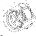
- Fig. 5 illustrates the wind turbine rotor with the wind turbine hub (02) and a plurality of rotor blades connections (10, 11, 12) with rotor blades (05, 06, 07) mounted thereon.
- Fig. 6 illustrates the rotor hub carrier (01) with a plurality of wind jet turbine shaft carriers (23, 24) and maintenance holes (18) in the front part (21) of the wind turbine rotor hub carrier (01).
- the wind jet turbine shaft carriers (23, 24) are assembled before and after the maintenance holes (18).
- the front part (21) of the rotor hub carrier (01) has a smaller outer diameter than the rear part (22) of the rotor hub carrier (01).
- Fig. 7 illustrates the rotor hub carrier (01).
- the front part of the rotor hub carrier (21) have a plurality of maintenance holes (18) to maintain the rotor blade connections (10, 11, 12) and the pitch system of the rotor blades.
- the rear part of the rotor hub carrier (22) is mounted on the tower (04).
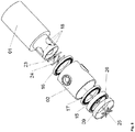
- Fig. 8 illustrates an exploded view of the wind turbine nacelle.
- the wind jet turbine funnel (09) ensures that the wind stream passes the construction height (31) from the outer part of the wind turbine hub (02) to the inner part of the system.
- the funnel (09) and the wind turbine hub carrier (01) also act as a shroud which surrounds the generator assembly.
- Fig. 10 illustrates the assembly of the embodiments of the wind turbine nacelle.
- Fig. 10 also show the connection of the wind turbine hub carrier (01) via a plurality of bearings (16, 17) with the wind turbine rotor hub (02).
- the rear part of the wind turbine hub (20) and the front part of the wind turbine hub carrier (21) are plugged/assembled, via bearings (16, 17), onto each other so that the wind turbine rotor hub (02) rotates with its rear part (20) on the front part (21) of the wind turbine hub carrier (01).
- Fig. 11 is the schematic illustration of the turbine system where the term construction height is defined.
- the funnel directs the wind stream to bypass the structural height (construction height) (31) of the assembly inside the wind jet turbine.
- Fig. 12 illustrates a generator were the stator (33) is in the outer part of the generator.
- the inner part of the generator, the rotor (32) is assembled with a carrier (35).
- the carrier of the generator rotor has a hole (34) for the wind jet turbine shaft (26).
- the wind jet turbine shaft (26) is connected to the generator carrier (35) over the shaft hole (34).
- Fig. 13 illustrates an alternative generator were the rotor (42) is in the outer part of the generator.
- the inner part of the generator, the stator (43), is assembled with a carrier (45).
- the carrier of the generator stator has a hole (44) for the wind jet turbine shaft (26).
- the wind jet turbine shaft (26) is connected to the generator stator carrier (45) over the shaft hole (44).
- Fig. 14 is a perspective view of a further alternative generator where the rotor (52) and the stator (53) are arranged in series and where the rotor (52) and the stator (53) rotates axial in different directions to each other.
- Fig. 15 illustrates the wind jet turbine rotor (25) with a plurality of wind jet turbine blades (28) and the wind jet turbine hub (27).
- Fig. 19 illustrates the rotor hub carrier (01) with a plurality of wind jet turbine shaft carriers (23, 24) and maintenance holes (18) and the arrangement of the bearings (16, 17) which carry the wind turbine rotor hub (02).
- a wind turbine system comprising:
Landscapes
- Engineering & Computer Science (AREA)
- Life Sciences & Earth Sciences (AREA)
- Sustainable Development (AREA)
- Sustainable Energy (AREA)
- Chemical & Material Sciences (AREA)
- Combustion & Propulsion (AREA)
- Mechanical Engineering (AREA)
- General Engineering & Computer Science (AREA)
- Power Engineering (AREA)
- Wind Motors (AREA)
Priority Applications (1)
| Application Number | Priority Date | Filing Date | Title |
|---|---|---|---|
| EP17167730.5A EP3396153A1 (fr) | 2017-04-24 | 2017-04-24 | Une combinaison d'une turbine à jet de vent et d'une éolienne |
Applications Claiming Priority (1)
| Application Number | Priority Date | Filing Date | Title |
|---|---|---|---|
| EP17167730.5A EP3396153A1 (fr) | 2017-04-24 | 2017-04-24 | Une combinaison d'une turbine à jet de vent et d'une éolienne |
Publications (1)
| Publication Number | Publication Date |
|---|---|
| EP3396153A1 true EP3396153A1 (fr) | 2018-10-31 |
Family
ID=58632249
Family Applications (1)
| Application Number | Title | Priority Date | Filing Date |
|---|---|---|---|
| EP17167730.5A Withdrawn EP3396153A1 (fr) | 2017-04-24 | 2017-04-24 | Une combinaison d'une turbine à jet de vent et d'une éolienne |
Country Status (1)
| Country | Link |
|---|---|
| EP (1) | EP3396153A1 (fr) |
Cited By (2)
| Publication number | Priority date | Publication date | Assignee | Title |
|---|---|---|---|---|
| US11293410B1 (en) | 2021-07-28 | 2022-04-05 | Breezy Wind Turbines LLC | Direct drive wind turbine |
| US20230287867A1 (en) * | 2020-08-03 | 2023-09-14 | Nikolai Nikolayevich TERESHCHUK | Vimproved horizontal wind turbine |
Citations (12)
| Publication number | Priority date | Publication date | Assignee | Title |
|---|---|---|---|---|
| US1944239A (en) * | 1930-03-19 | 1934-01-23 | Honnef Hermann | Electric wind dynamo |
| FR1007883A (fr) * | 1948-04-10 | 1952-05-12 | Scient Et Tech Bureau Et | Installation éolienne pour exploitation isolée |
| US4039848A (en) | 1975-11-10 | 1977-08-02 | Winderl William R | Wind operated generator |
| DE2717043A1 (de) * | 1977-04-18 | 1978-10-19 | Ludwig Naake | Stauduesenturbine als windkraftwerk |
| EP0053972A1 (fr) * | 1980-12-01 | 1982-06-16 | Jean Frédéric Georges Charpentier | Turbo machine convertissant sous très haut rendement l'énergie dynamique des fluides en énergie mécanique |
| DE29506153U1 (de) * | 1995-04-08 | 1995-07-27 | Wirths Ernst Albert | Windturbine |
| US5506453A (en) | 1990-02-09 | 1996-04-09 | Mccombs; John C. | Machine for converting wind energy to electrical energy |
| US6278197B1 (en) | 2000-02-05 | 2001-08-21 | Kari Appa | Contra-rotating wind turbine system |
| WO2010107830A1 (fr) | 2009-03-16 | 2010-09-23 | Bersiek Shamel A | Eolienne |
| US7914261B2 (en) | 2002-06-05 | 2011-03-29 | Aloys Wobben | Rotor blade for a wind power plant |
| US8021100B2 (en) | 2007-03-23 | 2011-09-20 | Flodesign Wind Turbine Corporation | Wind turbine with mixers and ejectors |
| US20120051916A1 (en) | 2011-04-26 | 2012-03-01 | General Electric Company | Wind turbine with auxiliary fins |
-
2017
- 2017-04-24 EP EP17167730.5A patent/EP3396153A1/fr not_active Withdrawn
Patent Citations (13)
| Publication number | Priority date | Publication date | Assignee | Title |
|---|---|---|---|---|
| US1944239A (en) * | 1930-03-19 | 1934-01-23 | Honnef Hermann | Electric wind dynamo |
| FR1007883A (fr) * | 1948-04-10 | 1952-05-12 | Scient Et Tech Bureau Et | Installation éolienne pour exploitation isolée |
| US4039848A (en) | 1975-11-10 | 1977-08-02 | Winderl William R | Wind operated generator |
| DE2717043A1 (de) * | 1977-04-18 | 1978-10-19 | Ludwig Naake | Stauduesenturbine als windkraftwerk |
| EP0053972A1 (fr) * | 1980-12-01 | 1982-06-16 | Jean Frédéric Georges Charpentier | Turbo machine convertissant sous très haut rendement l'énergie dynamique des fluides en énergie mécanique |
| US5506453A (en) | 1990-02-09 | 1996-04-09 | Mccombs; John C. | Machine for converting wind energy to electrical energy |
| DE29506153U1 (de) * | 1995-04-08 | 1995-07-27 | Wirths Ernst Albert | Windturbine |
| US6278197B1 (en) | 2000-02-05 | 2001-08-21 | Kari Appa | Contra-rotating wind turbine system |
| US7914261B2 (en) | 2002-06-05 | 2011-03-29 | Aloys Wobben | Rotor blade for a wind power plant |
| US8100663B2 (en) | 2002-06-05 | 2012-01-24 | Aloys Wobben | Rotor blade for a wind power plant |
| US8021100B2 (en) | 2007-03-23 | 2011-09-20 | Flodesign Wind Turbine Corporation | Wind turbine with mixers and ejectors |
| WO2010107830A1 (fr) | 2009-03-16 | 2010-09-23 | Bersiek Shamel A | Eolienne |
| US20120051916A1 (en) | 2011-04-26 | 2012-03-01 | General Electric Company | Wind turbine with auxiliary fins |
Non-Patent Citations (3)
| Title |
|---|
| "HAU, Erich. Wind Turbines", 2013, SPRINGER-VERLAG, pages: 879 |
| QUASCHNING, VOLKER: "Regenerative Energiesysteme", 2015, CARL HANSER VERLAG, pages: 444 |
| QUASCHNING, VOLKER: "Regenerative Energiesysteme", pages: 275 |
Cited By (3)
| Publication number | Priority date | Publication date | Assignee | Title |
|---|---|---|---|---|
| US20230287867A1 (en) * | 2020-08-03 | 2023-09-14 | Nikolai Nikolayevich TERESHCHUK | Vimproved horizontal wind turbine |
| US11293410B1 (en) | 2021-07-28 | 2022-04-05 | Breezy Wind Turbines LLC | Direct drive wind turbine |
| US11629700B2 (en) | 2021-07-28 | 2023-04-18 | Breezy Wind Turbines LLC | Direct drive wind turbine |
Similar Documents
| Publication | Publication Date | Title |
|---|---|---|
| EP2821635B1 (fr) | Ensemble de moyeu aérodynamique pour une turbine éolienne | |
| US9512817B2 (en) | Diffuser augmented wind turbines | |
| US20090148285A1 (en) | Multi-section wind turbine rotor blades and wind turbines incorporating same | |
| EP2699796B1 (fr) | Turbines éoliennes amplifiées par un diffuseur | |
| US20100111697A1 (en) | Wind energy generation device | |
| US20040042894A1 (en) | Wind-driven electrical power-generating device | |
| GB2463957A (en) | Multiple rotor vertical axis wind turbine | |
| EP2587056A2 (fr) | Éolienne avec ensemble de transmission compacte à un étage | |
| AU2016232938B2 (en) | Improved wind turbine suitable for mounting without a wind turbine tower | |
| US20180171966A1 (en) | Wind turbine with rotating augmentor | |
| US20140227095A1 (en) | Pivotal jet wind turbine | |
| EP3396153A1 (fr) | Une combinaison d'une turbine à jet de vent et d'une éolienne | |
| EP2923077B1 (fr) | Rotor de turbine éolienne et ses procédés d'assemblage | |
| JP2012092651A (ja) | 風力発電装置 | |
| US20110070065A1 (en) | Wind energy device with increased wind speed feature | |
| RU2310090C1 (ru) | Ветроэнергетическое устройство | |
| KR101810872B1 (ko) | 다중 풍력발전장치 | |
| KR100906811B1 (ko) | 수직축형 풍력 발전 장치 | |
| WO2008120026A2 (fr) | Eolienne à axe horizontal innovante présentant un rendement élevé | |
| CN202832975U (zh) | 两叶片离心变桨风力发电机 | |
| JP2019082135A (ja) | 風力発電装置 | |
| JP6047961B2 (ja) | 風力発電装置 | |
| US20230287867A1 (en) | Vimproved horizontal wind turbine | |
| KR100906814B1 (ko) | 수직축형 풍력 발전 장치용 로터 | |
| KR20070099377A (ko) | 다단계 풍력 발전기 |
Legal Events
| Date | Code | Title | Description |
|---|---|---|---|
| PUAI | Public reference made under article 153(3) epc to a published international application that has entered the european phase |
Free format text: ORIGINAL CODE: 0009012 |
|
| AK | Designated contracting states |
Kind code of ref document: A1 Designated state(s): AL AT BE BG CH CY CZ DE DK EE ES FI FR GB GR HR HU IE IS IT LI LT LU LV MC MK MT NL NO PL PT RO RS SE SI SK SM TR |
|
| AX | Request for extension of the european patent |
Extension state: BA ME |
|
| RAP1 | Party data changed (applicant data changed or rights of an application transferred) |
Owner name: OSTERTAG, ALBERT |
|
| RIN1 | Information on inventor provided before grant (corrected) |
Inventor name: OSTERTAG, ALBERT |
|
| STAA | Information on the status of an ep patent application or granted ep patent |
Free format text: STATUS: THE APPLICATION IS DEEMED TO BE WITHDRAWN |
|
| 18D | Application deemed to be withdrawn |
Effective date: 20190501 |