EP2921702B1 - Unité pompes-moteur - Google Patents
Unité pompes-moteur Download PDFInfo
- Publication number
- EP2921702B1 EP2921702B1 EP15158367.1A EP15158367A EP2921702B1 EP 2921702 B1 EP2921702 B1 EP 2921702B1 EP 15158367 A EP15158367 A EP 15158367A EP 2921702 B1 EP2921702 B1 EP 2921702B1
- Authority
- EP
- European Patent Office
- Prior art keywords
- channel
- leakage
- rotor
- shaft
- pinion
- Prior art date
- Legal status (The legal status is an assumption and is not a legal conclusion. Google has not performed a legal analysis and makes no representation as to the accuracy of the status listed.)
- Active
Links
- 239000012530 fluid Substances 0.000 claims description 63
- 238000007789 sealing Methods 0.000 description 144
- 210000003734 kidney Anatomy 0.000 description 18
- 239000000945 filler Substances 0.000 description 9
- 238000001816 cooling Methods 0.000 description 5
- 230000018109 developmental process Effects 0.000 description 5
- 238000005461 lubrication Methods 0.000 description 5
- 239000000696 magnetic material Substances 0.000 description 5
- 230000036316 preload Effects 0.000 description 5
- 230000004323 axial length Effects 0.000 description 4
- 230000001419 dependent effect Effects 0.000 description 4
- 230000010349 pulsation Effects 0.000 description 4
- XLYOFNOQVPJJNP-UHFFFAOYSA-N water Substances O XLYOFNOQVPJJNP-UHFFFAOYSA-N 0.000 description 4
- 238000004804 winding Methods 0.000 description 4
- RYGMFSIKBFXOCR-UHFFFAOYSA-N Copper Chemical compound [Cu] RYGMFSIKBFXOCR-UHFFFAOYSA-N 0.000 description 3
- 230000000903 blocking effect Effects 0.000 description 3
- 229910052802 copper Inorganic materials 0.000 description 3
- 239000010949 copper Substances 0.000 description 3
- 230000000694 effects Effects 0.000 description 3
- 210000003746 feather Anatomy 0.000 description 3
- 230000006872 improvement Effects 0.000 description 3
- 238000004519 manufacturing process Methods 0.000 description 3
- 239000000463 material Substances 0.000 description 3
- 230000009467 reduction Effects 0.000 description 3
- XEEYBQQBJWHFJM-UHFFFAOYSA-N Iron Chemical compound [Fe] XEEYBQQBJWHFJM-UHFFFAOYSA-N 0.000 description 2
- 230000008901 benefit Effects 0.000 description 2
- 230000005540 biological transmission Effects 0.000 description 2
- 230000008878 coupling Effects 0.000 description 2
- 238000010168 coupling process Methods 0.000 description 2
- 238000005859 coupling reaction Methods 0.000 description 2
- 238000005553 drilling Methods 0.000 description 2
- 238000001125 extrusion Methods 0.000 description 2
- 238000009434 installation Methods 0.000 description 2
- 229910052751 metal Inorganic materials 0.000 description 2
- 239000002184 metal Substances 0.000 description 2
- 230000035515 penetration Effects 0.000 description 2
- 239000004033 plastic Substances 0.000 description 2
- 229920003023 plastic Polymers 0.000 description 2
- 238000004382 potting Methods 0.000 description 2
- 238000003825 pressing Methods 0.000 description 2
- 150000003839 salts Chemical class 0.000 description 2
- 230000035939 shock Effects 0.000 description 2
- 239000000243 solution Substances 0.000 description 2
- 230000007704 transition Effects 0.000 description 2
- 229910001369 Brass Inorganic materials 0.000 description 1
- 229920002430 Fibre-reinforced plastic Polymers 0.000 description 1
- 229910052782 aluminium Inorganic materials 0.000 description 1
- XAGFODPZIPBFFR-UHFFFAOYSA-N aluminium Chemical compound [Al] XAGFODPZIPBFFR-UHFFFAOYSA-N 0.000 description 1
- 230000002146 bilateral effect Effects 0.000 description 1
- 239000010951 brass Substances 0.000 description 1
- 238000005256 carbonitriding Methods 0.000 description 1
- 238000005266 casting Methods 0.000 description 1
- 239000011248 coating agent Substances 0.000 description 1
- 238000000576 coating method Methods 0.000 description 1
- 150000001875 compounds Chemical group 0.000 description 1
- 238000006073 displacement reaction Methods 0.000 description 1
- 238000005516 engineering process Methods 0.000 description 1
- 239000011151 fibre-reinforced plastic Substances 0.000 description 1
- 230000004907 flux Effects 0.000 description 1
- 230000017525 heat dissipation Effects 0.000 description 1
- 230000001771 impaired effect Effects 0.000 description 1
- 238000001746 injection moulding Methods 0.000 description 1
- 230000003993 interaction Effects 0.000 description 1
- 229910052742 iron Inorganic materials 0.000 description 1
- 238000003475 lamination Methods 0.000 description 1
- 230000014759 maintenance of location Effects 0.000 description 1
- 230000007257 malfunction Effects 0.000 description 1
- 238000000034 method Methods 0.000 description 1
- 238000003801 milling Methods 0.000 description 1
- 238000005121 nitriding Methods 0.000 description 1
- 238000005457 optimization Methods 0.000 description 1
- 230000002093 peripheral effect Effects 0.000 description 1
- 230000002028 premature Effects 0.000 description 1
- 230000008569 process Effects 0.000 description 1
- 238000005245 sintering Methods 0.000 description 1
- 238000003892 spreading Methods 0.000 description 1
- 230000007480 spreading Effects 0.000 description 1
- 238000013022 venting Methods 0.000 description 1
- 239000002347 wear-protection layer Substances 0.000 description 1
Images


Classifications
-
- F—MECHANICAL ENGINEERING; LIGHTING; HEATING; WEAPONS; BLASTING
- F04—POSITIVE - DISPLACEMENT MACHINES FOR LIQUIDS; PUMPS FOR LIQUIDS OR ELASTIC FLUIDS
- F04C—ROTARY-PISTON, OR OSCILLATING-PISTON, POSITIVE-DISPLACEMENT MACHINES FOR LIQUIDS; ROTARY-PISTON, OR OSCILLATING-PISTON, POSITIVE-DISPLACEMENT PUMPS
- F04C11/00—Combinations of two or more machines or pumps, each being of rotary-piston or oscillating-piston type; Pumping installations
- F04C11/008—Enclosed motor pump units
-
- F—MECHANICAL ENGINEERING; LIGHTING; HEATING; WEAPONS; BLASTING
- F04—POSITIVE - DISPLACEMENT MACHINES FOR LIQUIDS; PUMPS FOR LIQUIDS OR ELASTIC FLUIDS
- F04B—POSITIVE-DISPLACEMENT MACHINES FOR LIQUIDS; PUMPS
- F04B17/00—Pumps characterised by combination with, or adaptation to, specific driving engines or motors
- F04B17/03—Pumps characterised by combination with, or adaptation to, specific driving engines or motors driven by electric motors
-
- F—MECHANICAL ENGINEERING; LIGHTING; HEATING; WEAPONS; BLASTING
- F04—POSITIVE - DISPLACEMENT MACHINES FOR LIQUIDS; PUMPS FOR LIQUIDS OR ELASTIC FLUIDS
- F04B—POSITIVE-DISPLACEMENT MACHINES FOR LIQUIDS; PUMPS
- F04B53/00—Component parts, details or accessories not provided for in, or of interest apart from, groups F04B1/00 - F04B23/00 or F04B39/00 - F04B47/00
- F04B53/04—Draining
-
- F—MECHANICAL ENGINEERING; LIGHTING; HEATING; WEAPONS; BLASTING
- F04—POSITIVE - DISPLACEMENT MACHINES FOR LIQUIDS; PUMPS FOR LIQUIDS OR ELASTIC FLUIDS
- F04C—ROTARY-PISTON, OR OSCILLATING-PISTON, POSITIVE-DISPLACEMENT MACHINES FOR LIQUIDS; ROTARY-PISTON, OR OSCILLATING-PISTON, POSITIVE-DISPLACEMENT PUMPS
- F04C14/00—Control of, monitoring of, or safety arrangements for, machines, pumps or pumping installations
- F04C14/04—Control of, monitoring of, or safety arrangements for, machines, pumps or pumping installations specially adapted for reversible machines or pumps
-
- F—MECHANICAL ENGINEERING; LIGHTING; HEATING; WEAPONS; BLASTING
- F04—POSITIVE - DISPLACEMENT MACHINES FOR LIQUIDS; PUMPS FOR LIQUIDS OR ELASTIC FLUIDS
- F04C—ROTARY-PISTON, OR OSCILLATING-PISTON, POSITIVE-DISPLACEMENT MACHINES FOR LIQUIDS; ROTARY-PISTON, OR OSCILLATING-PISTON, POSITIVE-DISPLACEMENT PUMPS
- F04C15/00—Component parts, details or accessories of machines, pumps or pumping installations, not provided for in groups F04C2/00 - F04C14/00
- F04C15/0003—Sealing arrangements in rotary-piston machines or pumps
- F04C15/0007—Radial sealings for working fluid
- F04C15/0019—Radial sealing elements specially adapted for intermeshing-engagement type machines or pumps, e.g. gear machines or pumps
-
- F—MECHANICAL ENGINEERING; LIGHTING; HEATING; WEAPONS; BLASTING
- F04—POSITIVE - DISPLACEMENT MACHINES FOR LIQUIDS; PUMPS FOR LIQUIDS OR ELASTIC FLUIDS
- F04C—ROTARY-PISTON, OR OSCILLATING-PISTON, POSITIVE-DISPLACEMENT MACHINES FOR LIQUIDS; ROTARY-PISTON, OR OSCILLATING-PISTON, POSITIVE-DISPLACEMENT PUMPS
- F04C15/00—Component parts, details or accessories of machines, pumps or pumping installations, not provided for in groups F04C2/00 - F04C14/00
- F04C15/0003—Sealing arrangements in rotary-piston machines or pumps
- F04C15/0023—Axial sealings for working fluid
- F04C15/0026—Elements specially adapted for sealing of the lateral faces of intermeshing-engagement type machines or pumps, e.g. gear machines or pumps
-
- F—MECHANICAL ENGINEERING; LIGHTING; HEATING; WEAPONS; BLASTING
- F04—POSITIVE - DISPLACEMENT MACHINES FOR LIQUIDS; PUMPS FOR LIQUIDS OR ELASTIC FLUIDS
- F04C—ROTARY-PISTON, OR OSCILLATING-PISTON, POSITIVE-DISPLACEMENT MACHINES FOR LIQUIDS; ROTARY-PISTON, OR OSCILLATING-PISTON, POSITIVE-DISPLACEMENT PUMPS
- F04C15/00—Component parts, details or accessories of machines, pumps or pumping installations, not provided for in groups F04C2/00 - F04C14/00
- F04C15/0042—Systems for the equilibration of forces acting on the machines or pump
- F04C15/0046—Internal leakage control
-
- F—MECHANICAL ENGINEERING; LIGHTING; HEATING; WEAPONS; BLASTING
- F04—POSITIVE - DISPLACEMENT MACHINES FOR LIQUIDS; PUMPS FOR LIQUIDS OR ELASTIC FLUIDS
- F04C—ROTARY-PISTON, OR OSCILLATING-PISTON, POSITIVE-DISPLACEMENT MACHINES FOR LIQUIDS; ROTARY-PISTON, OR OSCILLATING-PISTON, POSITIVE-DISPLACEMENT PUMPS
- F04C15/00—Component parts, details or accessories of machines, pumps or pumping installations, not provided for in groups F04C2/00 - F04C14/00
- F04C15/0057—Driving elements, brakes, couplings, transmission specially adapted for machines or pumps
- F04C15/008—Prime movers
-
- F—MECHANICAL ENGINEERING; LIGHTING; HEATING; WEAPONS; BLASTING
- F04—POSITIVE - DISPLACEMENT MACHINES FOR LIQUIDS; PUMPS FOR LIQUIDS OR ELASTIC FLUIDS
- F04C—ROTARY-PISTON, OR OSCILLATING-PISTON, POSITIVE-DISPLACEMENT MACHINES FOR LIQUIDS; ROTARY-PISTON, OR OSCILLATING-PISTON, POSITIVE-DISPLACEMENT PUMPS
- F04C15/00—Component parts, details or accessories of machines, pumps or pumping installations, not provided for in groups F04C2/00 - F04C14/00
- F04C15/0088—Lubrication
-
- F—MECHANICAL ENGINEERING; LIGHTING; HEATING; WEAPONS; BLASTING
- F04—POSITIVE - DISPLACEMENT MACHINES FOR LIQUIDS; PUMPS FOR LIQUIDS OR ELASTIC FLUIDS
- F04C—ROTARY-PISTON, OR OSCILLATING-PISTON, POSITIVE-DISPLACEMENT MACHINES FOR LIQUIDS; ROTARY-PISTON, OR OSCILLATING-PISTON, POSITIVE-DISPLACEMENT PUMPS
- F04C15/00—Component parts, details or accessories of machines, pumps or pumping installations, not provided for in groups F04C2/00 - F04C14/00
- F04C15/0096—Heating; Cooling
-
- F—MECHANICAL ENGINEERING; LIGHTING; HEATING; WEAPONS; BLASTING
- F04—POSITIVE - DISPLACEMENT MACHINES FOR LIQUIDS; PUMPS FOR LIQUIDS OR ELASTIC FLUIDS
- F04C—ROTARY-PISTON, OR OSCILLATING-PISTON, POSITIVE-DISPLACEMENT MACHINES FOR LIQUIDS; ROTARY-PISTON, OR OSCILLATING-PISTON, POSITIVE-DISPLACEMENT PUMPS
- F04C2/00—Rotary-piston machines or pumps
- F04C2/08—Rotary-piston machines or pumps of intermeshing-engagement type, i.e. with engagement of co-operating members similar to that of toothed gearing
- F04C2/082—Details specially related to intermeshing engagement type machines or pumps
- F04C2/084—Toothed wheels
-
- F—MECHANICAL ENGINEERING; LIGHTING; HEATING; WEAPONS; BLASTING
- F04—POSITIVE - DISPLACEMENT MACHINES FOR LIQUIDS; PUMPS FOR LIQUIDS OR ELASTIC FLUIDS
- F04C—ROTARY-PISTON, OR OSCILLATING-PISTON, POSITIVE-DISPLACEMENT MACHINES FOR LIQUIDS; ROTARY-PISTON, OR OSCILLATING-PISTON, POSITIVE-DISPLACEMENT PUMPS
- F04C2/00—Rotary-piston machines or pumps
- F04C2/08—Rotary-piston machines or pumps of intermeshing-engagement type, i.e. with engagement of co-operating members similar to that of toothed gearing
- F04C2/10—Rotary-piston machines or pumps of intermeshing-engagement type, i.e. with engagement of co-operating members similar to that of toothed gearing of internal-axis type with the outer member having more teeth or tooth-equivalents, e.g. rollers, than the inner member
- F04C2/101—Rotary-piston machines or pumps of intermeshing-engagement type, i.e. with engagement of co-operating members similar to that of toothed gearing of internal-axis type with the outer member having more teeth or tooth-equivalents, e.g. rollers, than the inner member with a crescent-shaped filler element, located between the inner and outer intermeshing members
-
- F—MECHANICAL ENGINEERING; LIGHTING; HEATING; WEAPONS; BLASTING
- F04—POSITIVE - DISPLACEMENT MACHINES FOR LIQUIDS; PUMPS FOR LIQUIDS OR ELASTIC FLUIDS
- F04C—ROTARY-PISTON, OR OSCILLATING-PISTON, POSITIVE-DISPLACEMENT MACHINES FOR LIQUIDS; ROTARY-PISTON, OR OSCILLATING-PISTON, POSITIVE-DISPLACEMENT PUMPS
- F04C2/00—Rotary-piston machines or pumps
- F04C2/08—Rotary-piston machines or pumps of intermeshing-engagement type, i.e. with engagement of co-operating members similar to that of toothed gearing
- F04C2/10—Rotary-piston machines or pumps of intermeshing-engagement type, i.e. with engagement of co-operating members similar to that of toothed gearing of internal-axis type with the outer member having more teeth or tooth-equivalents, e.g. rollers, than the inner member
- F04C2/102—Rotary-piston machines or pumps of intermeshing-engagement type, i.e. with engagement of co-operating members similar to that of toothed gearing of internal-axis type with the outer member having more teeth or tooth-equivalents, e.g. rollers, than the inner member the two members rotating simultaneously around their respective axes
-
- F—MECHANICAL ENGINEERING; LIGHTING; HEATING; WEAPONS; BLASTING
- F04—POSITIVE - DISPLACEMENT MACHINES FOR LIQUIDS; PUMPS FOR LIQUIDS OR ELASTIC FLUIDS
- F04C—ROTARY-PISTON, OR OSCILLATING-PISTON, POSITIVE-DISPLACEMENT MACHINES FOR LIQUIDS; ROTARY-PISTON, OR OSCILLATING-PISTON, POSITIVE-DISPLACEMENT PUMPS
- F04C29/00—Component parts, details or accessories of pumps or pumping installations, not provided for in groups F04C18/00 - F04C28/00
- F04C29/02—Lubrication; Lubricant separation
- F04C29/023—Lubricant distribution through a hollow driving shaft
-
- F—MECHANICAL ENGINEERING; LIGHTING; HEATING; WEAPONS; BLASTING
- F04—POSITIVE - DISPLACEMENT MACHINES FOR LIQUIDS; PUMPS FOR LIQUIDS OR ELASTIC FLUIDS
- F04C—ROTARY-PISTON, OR OSCILLATING-PISTON, POSITIVE-DISPLACEMENT MACHINES FOR LIQUIDS; ROTARY-PISTON, OR OSCILLATING-PISTON, POSITIVE-DISPLACEMENT PUMPS
- F04C2240/00—Components
- F04C2240/60—Shafts
- F04C2240/603—Shafts with internal channels for fluid distribution, e.g. hollow shaft
Definitions
- the invention relates to a motor-pump unit which comprises an internal gear machine for reversing operation and an electric motor which is coupled to the internal gear machine via a shaft.
- a motor-pump unit can be used, for example, to control a highly dynamic hydraulic axis.
- Such motor-pump units are in the publications EP 2 128 446 A2 , WO 2013/099505 A1 , DE 15 53 026 A1 , U.S. 1,819,228 A , U.S. 2,469,820 A shown.
- the invention relates to a motor-pump unit with a multi-part housing, which comprises an internal gear machine for reversing operation and an electric motor with a rotor and a stator, which is coupled to the internal gear machine via at least one shaft rotatably mounted in the housing about a shaft rotation axis, wherein the electric motor comprises a rotor arranged in a housing part of the housing, rotatable about a rotor axis of rotation and a stator, and wherein the internal gear machine comprises a working chamber which is delimited by at least two housing parts of the housing and in which two gears are arranged, which are is an externally toothed pinion having pinion teeth and an internally toothed ring gear which is mounted eccentrically with respect to the pinion, ring gear teeth of the ring gear teeth of the ring gear in a tooth meshing area with pinion teeth of the pinion teeth of the pinion, and the pinion gear are rotatably mounted about a
- the shaft extends with one shaft end away from the pinion in the axial direction through the rotor carried by the shaft.
- the first connection channel and the second connection channel are connected via check valves arranged in the housing or in a housing part delimiting the working chamber to a leakage channel loop which is fluidly connected to the at least one leakage channel and which extends at least into a region of a rotor end extending away from the pinion of the rotor and the one in the axial direction in the shaft or through the shaft extending leakage shaft channel and at least one fluid-connected to the leakage shaft channel, preferably at a radial distance from the leakage shaft channel, in the axial direction in the Rotor or leakage rotor duct extending through the rotor and / or a leakage gap duct which is fluidly connected to the leakage shaft duct and is formed between the rotor and the stator and which extends in the axial direction, viewed in the radial direction.
- the non-return valves close in a fluid flow direction from the leakage channel loop, preferably open the currently active low pressure area, the working chamber and block in an opposite direction or opposite fluid flow direction, preferably from the respectively active high pressure area of the working chamber to the leakage channel loop, so that the internal gear unit is in operation the leakage fluid flows from the at least one leakage channel through the leakage channel loop into the working chamber, preferably and from there essentially, except for a leakage portion, into the connection channel assigned to the respective active low-pressure area.
- a sickle-shaped free space is formed between the pinion and the ring gear.
- a one-part or multi-part filler piece can be arranged in the sickle-shaped free space.
- a sickle-shaped free space is formed between the pinion and the ring gear, in which a multi-part filler is arranged, the several in radial Radial sealing segments that are movable relative to one another in the direction of radial sealing of a high-pressure area of the working chamber, of which a first radial sealing segment forms a pinion segment that can be applied or rests against the pinion teeth of the pinion teeth of the pinion and of which a second radial seal segment forms a ring gear segment that can be applied to the ring gear teeth of the ring gear teeth of the ring gear.
- At least one axial sealing plate movable in the axial direction, for axially sealing the high-pressure area of the working chamber is arranged between the axial end faces of the gearwheels and at least one housing part of the housing.
- a radial gap is formed between an inner surface of the pinion segment pointing radially outward toward the ring gear segment and an inner surface of the ring gear segment opposite this, pointing radially inward toward the pinion segment.
- the at least one leakage channel is directly fluidly connected to the leakage shaft channel of the leakage channel loop and that the at least one leakage rotor channel of the leakage channel loop is directly connected to one in a housing part of the housing or in the one containing the at least one leakage channel Housing part of the housing arranged connection channel or connecting space is fluidly connected, so that during operation of the internal gear machine the leakage fluid flows either from the at least one leakage channel through the leakage shaft channel and into and through the at least one leakage rotor channel of the leakage channel loop and from there into the connection channel or into the connection space, or vice versa, or that the at least one leakage channel is directly fluidly connected to the at least one leakage rotor channel of the leakage channel loop and that the at least one leakage shaft channel of the leakage channel loop is directly connected to a housing part in a housing part of the housing or in the housing part containing the at least one leakage channel of the housing arranged connecting channel or connecting space is fluid-connected
- a first return flow channel and a second return flow channel are arranged in a housing part of the housing between the working chamber and the connecting channel or the connecting space, each of which ends at one end in the connecting channel or connecting space and at the other end, preferably in one Opening of the respective connection channel into the opening area opposite the working chamber, opening into the working chamber, the first return flow channel containing a first non-return valve of the non-return valves and the second return flow channel containing a second non-return valve of the non-return valves so that during operation of the internal gear machine the leakage fluid through the leakage channel loop, preferably from the leakage channel through the leakage shaft channel into and through the at least one leakage rotor channel of the leakage channel loop, or vice versa, into and through the connecting channel or the connecting space and from there either flows into and through the first return channel via the first check valve into the working chamber or into and through the second return channel via the second check valve into the working chamber.
- first channel part of the first return flow channel opening into the working chamber and the first connection channel extend in the axial direction, preferably coaxially to one another, and that a second channel part of the second return flow channel opening into the working chamber and the second connection channel extend in the axial direction , preferably coaxial to one another, extend.
- the leakage shaft channel is an axial bore, the longitudinal axis of which is arranged coaxially to the rotor axis of rotation and / or coaxially to the shaft axis of rotation.
- the at least one leakage rotor channel is an axial recess, the recess longitudinal axis of which is arranged parallel to the pinion axis of rotation and / or parallel to the shaft axis of rotation.
- the rotor contains a plurality of leakage rotor channels extending through it in the axial direction, each of which ends with the leakage shaft channel are fluid-connected and which are fluid-connected at the other end to the working chamber and / or to the connecting channel or to the connecting space.
- the at least one leakage rotor duct extends through the rotor and is open towards rotor ends of the rotor pointing away from one another in the axial direction, or that the leakage rotor ducts extend through the rotor and towards the axial direction facing away from each other rotor ends of the rotor are open.
- the shaft has at least one radial recess which opens into the leakage shaft channel at one end and which is open radially outward at the other end and at least one in the area of the open to the shaft, preferably designed as an annular space Leakage channel is arranged for receiving the leakage fluid, so that during operation of the internal gear machine, the leakage fluid flows from the at least one leakage channel, preferably directly, into the leakage shaft channel.
- the shaft in the area of its shaft end assigned to the rotor or at its shaft end assigned to the rotor via a rotor bearing of the rotor on a housing part of the housing assigned to the electric motor around its rotor axis of rotation and / or around its shaft Axis of rotation is rotatably mounted, and that the leakage shaft channel of the shaft and the at least one leakage rotor channel of the rotor are fluidly connected to a bearing gap of the rotor bearing, so that during operation of the internal gear machine the leakage fluid flows to the bearing gap of the rotor bearing or through the bearing gap of the rotor bearing.
- the rotor bearing can preferably be a roller bearing or a ball bearing.
- the shaft has at least one radial recess which is arranged in the area of the rotor bearing and which opens into the leakage shaft channel at one end and the other end is fluidly connected to the bearing gap of the rotor bearing radially outwards first connection channel or, preferably designed as an annular space, connection space is open which is fluidly connected to the at least one leakage rotor duct or into which the at least one leakage rotor duct opens, so that during operation of the internal gear machine the leakage fluid from the leakage shaft duct into the with the bearing gap of the rotor bearing fluid-connected connection channel or into the connection space, preferably designed as an annular space, and from there into the at least one leakage rotor channel, or vice versa.
- a bearing fastening and / or sensor body is fastened to the shaft in the region of its shaft end assigned to the rotor, by means of which the rotor bearing is fastened to the shaft and / or which contains a sensor, preferably a speed sensor .
- the leakage shaft channel is releasably closed in the area of the shaft end of the shaft assigned to the rotor by means of the bearing fastening and / or sensor body.
- the bearing fastening and / or sensor body is a bearing fastening and / or sensor screw that is screwed to the shaft.
- the bearing fastening and / or sensor body can preferably consist of a non-magnetic material and the sensor can generate magnetic signals or generate magnetic signals.
- an axial recess fluidly connected to the leakage shaft channel is arranged in the bearing fastening and / or sensor body, which axial recess opens into a radial recess of the bearing fastening and / or sensor body which radially outwards to a or the connection channel fluidly connected to the bearing gap of the rotor bearing or, preferably designed as an annular space, connection space is open, which is arranged on a side of the rotor bearing facing away from the pinion, so that the leakage fluid from the leakage shaft channel during operation of the internal gear machine flows via the axial recess and the radial recess of the bearing fastening and / or sensor body and via the connecting channel or connecting space through the bearing gap of the rotor bearing into the at least one leakage rotor channel, or vice versa.
- a sealing tube which extends in the axial direction essentially over the entire length of the stator and is made of a non-magnetic material, is arranged the stator is attached and which is tightly connected to the stator against penetration of the fluid pressure medium or leakage fluid.
- the sealing tube with the stator including its windings or the wound phase lines and a housing part of the housing receiving the stator seal against penetration of the fluid pressure medium or the leakage fluid by means of a non-magnetic potting compound Unit is potted.
- the leakage gap channel viewed in the radial direction, is formed between the sealing tube and the rotor.
- the leakage gap channel is an annular leakage gap channel.
- the shaft is a one-piece and / or one-piece motor pump shaft to which the rotor is non-rotatably, preferably non-positively, fastened, in particular by pressing or shrinking, and to which the pinion is rotatably, preferably positively, in particular releasably attached.
- the electric motor is a brushless direct current motor (EC motor).
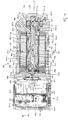
- the motor-pump unit 20 comprises an internal gear machine 21 for reversing operation, an electric motor 22 and integrated electronics 74, in particular for speed control.
- the electric motor 22 comprises a rotor 22.1 and a stator 22.2.
- the rotor 22.1 which can rotate about a rotor axis of rotation 34.1 relative to the stator 22.2, is connected in a rotationally fixed manner to a shaft 23 which can rotate about a shaft axis of rotation 35.
- the rotor 22.1 is coupled to the transmission of the internal gear machine 21 via the shaft 23.
- the shaft 23 is preferably a common, one-piece motor pump shaft.
- the motor pump shaft 23 is mounted in the housing 25 so as to be rotatable about a shaft axis of rotation 35.
- the motor-pump unit 20 can preferably be used to control a highly dynamic hydraulic axis, which is or are not shown in the figures.
- the motor-pump unit 20 comprises a multi-part housing 25 which contains both the electric motor 22 and the internal gear machine 10.
- both the rotor 22.1 and the stator 22.2 are arranged in a tubular housing part 25.3 of the housing 25 assigned to the motor 22.
- the stator could also form a component part of a housing part of the housing of the motor-pump unit or as a Housing part of the housing of the motor-pump unit could be formed.
- the internal gear machine 21 is a hydraulic machine in the form of a compensated four-quadrant internal gear machine 21.
- the motor-pump unit 20 is preferably used in a closed hydraulic system.
- the motor-pump unit 20 is characterized by high dynamics, low noise and pulsation, recuperation, a long service life, absolute freedom from leaks, service life filling of the system, insensitivity to shock and insensitivity to dirt, water, especially salt water, and temperature, especially cold .
- the motor-pump unit 20 has, in particular, the following design features:
- a hydraulic pump in the form of an internal gear pump with axial and radial sealing gap compensation is used as the internal gear machine 21.
- the internal gear machine 21 comprises a working chamber 24 which is delimited by preferably two housing parts 25.1 and 25.2 of the housing 25 of the motor-pump unit 20.
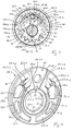
- Two gear wheels 26, 30 are arranged in the housing 25 or in the working chamber 24. These are an externally toothed pinion 26 having pinion teeth 28 and an internally toothed ring gear 30 having ring gear teeth 31.
- the ring gear 30 is mounted eccentrically in a bearing ring 27 with respect to the pinion 26.
- the bearing ring 27 is non-rotatably connected to the housing part 25.2 of the housing 25, preferably pressed in.
- the ring gear 30 is arranged in such a way that ring gear teeth of the ring gear teeth 31 of the ring gear 30 mesh with pinion teeth of the pinion teeth 28 of the pinion 26 in a tooth engagement region 33.
- the pinion 26 is about a pinion axis of rotation 34.2 rotatably mounted.
- the pinion rotation axis 34.2 is arranged coaxially to the shaft rotation axis 35 of the shaft 23.
- the ring gear 30 is mounted rotatably about a ring gear axis of rotation 36.
- the directions of rotation of pinion 26 and ring gear 30 are in the same direction. This means that if, for example, the pinion 26 rotates clockwise, then the ring gear 30 inevitably also rotates clockwise.
- the pinion 26 is preferably detachably connected to the shaft 23, for example by means of a feather key 37 which positively engages in matching grooves 38.1, 38.2 of both the shaft 23 and the pinion 26 (see FIG Figure 3 ). Consequently, the pinion 26 and the shaft 23 are positively connected to one another in a rotationally fixed manner.
- the ring gear axis of rotation 36 and the pinion axis of rotation 34.2 extend parallel to one another in an axial direction 39.
- a sickle-shaped free space 40 of the working chamber 24 is formed between the pinion 26 and the ring gear 30.
- a multi-part sickle-shaped filler piece 41 is arranged in the free space 40.
- the filler piece 41 comprises a plurality of radial sealing segments 42 which are movable relative to one another in the radial direction; 43.1, 43.2 for the radial sealing of the "active" high pressure area 44.1, 44.2 of the working chamber 24, which is dependent on the direction of rotation 104.1, 104.2.
- the high pressure area 44.1, 44.2 is assigned to that area of the working chamber 24 which, starting from a pressure build-up area of the working chamber 24, the during operation of the internal gear machine 21 corresponds approximately to the area in which the teeth 28, 31 of the gears 26, 30 reach the filler piece 41 or the area of the filler piece 41 in which at least one, preferably two, retaining pin (s) or retaining bolt 45.1, 45.2 for the filler piece 41 or for its radial sealing segments 42; 43.1, 43.2 is arranged in the respective direction of rotation 104.1, 104.2 viewed from pinion 26 or ring gear 30, extends up to the tooth engagement area 33 in which the teeth 28, 31 of the gears 26, 30 mesh with one another.
- the respective active high-pressure area 44.1, 44.2 is designed in the shape of a semi-sickle or kidney.
- first operating direction in which the pinion 26 and the ring gear 30 rotate in their first direction of rotation 104.1
- high fluid pressure is formed in a first area 44.1 of the working chamber 24, which is then the active first High pressure area 44.1 acts.
- a low fluid pressure then forms in the second region 44.2 of the working chamber.
- a first connection channel 105.1 opens into said first area 44.1 of the working chamber 24 and a second connection channel 105.2 opens into said second area 44.2 of the working chamber. (please refer Figure 12 ).
- the first connection channel preferably extend 105.2 and the second connection channel 105. parallel to one another in the axial direction 39
- the radial seal segments 42; 43.1, 43.2 comprise a first radial sealing segment which forms a pinion segment 42, which can also be referred to as a segment carrier and which can be placed or rests against pinion teeth of the pinion teeth 28 of the pinion 26.
- the pinion segment 42 is designed in one piece and made from one part, for example by milling.
- the radial seal segments 42; 43.1, 43.2 also include at least one second radial sealing segment which forms a ring gear segment 43.1, 43.2 and which can be placed or rests against the ring gear teeth of the ring gear teeth 31 of the ring gear 30.
- two separate ring gear segments 43.1, 43.2 are provided, of which each ring gear segment 43.1, 43.2 can be placed against the ring gear teeth of the ring gear teeth 31 of the ring gear 30.
- the pinion segment 42 In the area of each ring gear segment 43.1, 43.2, the pinion segment 42 has an inner surface 72 pointing radially outward toward the respective ring gear segment 43.1, 43.2.
- Each ring gear segment 43.1, 43.2 has an inner surface 73.1, 73.2 which points radially inward toward the pinion segment 42 and which lies opposite the associated inner surface 72 of the pinion segment 42.
- a radial gap 75.1, 75.2 is formed between the inner surface 72 of the pinion segment 42 and the inner surface 73.1, 73.2 of the respective ring gear segment 43.1, 43.2.
- pressure medium preferably pressure oil, passes from the active high pressure area 44.1, 44.2 assigned to the current direction of rotation of the pinion 26 and the ring gear 30 into the said radial gap 75.1, 75.2 or into the corresponding gap space, which is also is designated with compensation space.
- the pinion segment 43.1, 43.2 has two sealing roller grooves 48.1, 48.2 extending in the axial direction 39.
- Each sealing roller groove 48.1, 48.2 is open towards their axial ends pointing away from one another.
- a pretensioned sealing roller spring 50.1, 50.2, preferably a leaf spring, is also arranged in each sealing roller groove 48.1, 48.2.
- Each sealing roller spring 50.1, 50.2 is supported on the one hand on a groove base of the associated sealing roller groove 48.1, 48.2 and on the other hand is supported on the associated sealing roller 49.1, 49.2. This will make each sealing roller 49.1, 49.2 pressed against a sealing surface of the sealing roller groove 48.1, 48.2 of the pinion segment 42 and also against a sealing surface of the respectively assigned ring gear segment 43.1, 43.2 even in the depressurized state or when the internal gear machine 21 is not in operation.
- the pinion segment 42 has two segment spring grooves 51.1, 51.2 extending in the axial direction 39.
- Each segment spring groove 51.1, 51.2 is open towards their axial ends pointing away from one another.
- a pretensioned spring 52.2, 52.2, preferably a leaf spring, is received in each segment spring groove 51.1, 51.2.
- Each segmented spring groove 51.1, 51.2 is arranged offset in the circumferential direction at a circumferential distance or circumferential angle to the respectively assigned sealing roller groove 48.1, 48.2, namely in the direction of a pinion segment end 53.1, 53.2 of the pinion segment 42, which is dependent on the direction of rotation, high pressure area 44.1, 442 offset.
- the assigned ring gear segment 43.1, 43.2 and the pinion segment 42 are pressed away from one another or apart in the radial direction in such a way that the pinion segment 42 with a radially inwardly facing outer surface 46 rests against the ring gear teeth of the ring gear teeth 31 of the ring gear 30 in a sealing manner and that the ring gear segment 43.1, 43.2 with a radially outwardly facing outer surface 47.1, 47.2 which points away from the outer surface 46 of the pinion segment 42, rests sealingly on the ring gear teeth of the ring gear teeth 31 of the ring gear 30.
- the pinion segment 42 is designed as a segment carrier for the respective ring gear segment 43.1, 43.2 and has a stop 54.1, 54.2, which can also be referred to as a stop pocket, for each ring gear segment 43.1, 43.2. Every 54.1, 54.2 Stop has a stop surface 55.1, 55.2 extending in the axial direction 39 and radially outward towards the ring gear 30 to support the respective ring gear segment 43.1, 43.2 against drawing in of the respective ring gear segment 43.1, 43.2 during operation of the internal gear unit 21 in the tooth engagement area 33 .
- Each stop 54.1, 54.2 is with its stop surface 55.1, 55.2 at a circumferential distance or at a circumferential angle to the respective segment spring groove 51.1, 51.2 in the circumferential direction in the direction of the pinion segment end 53.1, 53.2 of the pinion segment 42 assigned to the active high pressure area 44.1, 44.2, which is dependent on the direction of rotation staggered.
- two axial sealing plates 58.1, 58.2 movable in the axial direction 39 are provided in the exemplary embodiment shown. These serve to seal off the high pressure area 44.1, 44.2 of the working chamber 24, which area is dependent on the direction of rotation of the gear wheels 26, 30.
- the axial sealing plates 58.1, 58.2 can also be referred to as axial washers. It goes without saying that only a single axial sealing disk can also be provided.
- the or each axial sealing disk 58.1, 58.2 is between the respectively assigned end faces 56.1, 56.2; 57.1, 57.2 of the gears 26, 30 and a housing part 25.1, 25.2 of the housing 25 are arranged.
- the or each axial sealing disk 58.1, 58.2 is in operation of the internal gear machine 21 by means of pressure medium under high pressure with their respective inner surface 59.1, 60.1 against the respectively assigned end faces 56.1, 56.2; 57.1, 57.2 of pinion 26 and ring gear 30 pressed.
- so-called pressure fields 61.1, 61.2 are provided, which can also be labeled with axial fields (see Figure 7 ).
- the pressure fields 61.1, 61.2 form control fields.
- the pressure fields 61.1, 61.2 are provided in the form of recesses in the respectively assigned housing part 25.1, 25.2 of the housing 25.
- the pressure fields or a pressure field assigned to an axial sealing plate can also be provided in the form of a recess in the axial sealing plate or in the respective axial sealing plate.
- the or each pressure field 61.1, 61.2 is designed in the shape of a kidney.
- the axial disks 58.1, 58.2 have kidney-shaped control fields 62.1, 62.2 on their inner sides 59.1, 60.1, i.e. those sides which face the pinion 26 and the ring gear 30, which are also referred to as sealing plate recesses or pressure kidneys (see Figures 4 and 5 ). These are recesses or depressions in the respective axial disk 58.1, 58.2.
- These control fields 62.1, 62.2 like the pressure fields 61.1, 61.2, can be acted upon with pressure medium under high pressure or are acted upon by pressure medium of the respective high pressure area 44.1, 44.2 during operation of the internal gear machine 21. As a result, a counterforce is generated which counteracts the force of the pressure fields 61.1, 61.2.
- Each pressure kidney 62.1, 62.2 are at least two control grooves 63.1.1, 63.1.2; 63.2.1, 63.2.2 assigned, each of which is assigned to the assigned end faces 56.1, 56.2; 57.1, 57.2 of the gears 26, 30 are open, of which a first control groove 63.1.1, 63.1.2 in the area of the pinion tooth gaps 29 formed between the pinion teeth 28 of the pinion 26 are connected directly to them is arranged opposite one another and of which a second control groove 63.2.1, 63.2.2 in the area of the ring gear tooth gaps 32 formed between the ring gear teeth 31 of the ring gear 30 is arranged directly opposite them (see Figure 5 ).
- Both the first control groove 63.1.1, 63.1.2 and the second control groove 63.2.1, 63.2.2 each open with a first end into the associated pressure kidney 62.1, 62.2.
- a control slot 64.1.1, 64.1.2; 62.2.1, 64.2.2 are provided in the form of a recess or depression in the respective axial disk 58.1, 58.2.
- Each control slot 64.1.1, 64.1.2; 62.2.1, 64.2.2 ends in the respectively assigned first and second control groove 63.1.1, 63.1.2; 63.2.1, 63.2.2.
- Each control slot 64.1.1, 64.1.2; 62.2.1, 64.2.2 extends approximately or essentially in the circumferential direction.
- the at least one axial sealing plate 58.1, 58.2 has on its end faces 56.1, 56.2; 57.1, 57.2 of the gears 26, 30 facing side or inner side 59.1, 60.1 at least one to the end faces 56.1, 56.2; 57.1, 57.2 of the gears 26, 30 open towards the sealing plate recess or recess 63.3.1, 63.3.2 in the form of an additional or third sealing plate control channel that can be acted upon by pressure medium and is designed as a sealing plate control groove.
- this is a third control channel from three control channels, each of which opens into the kidney-shaped sealing plate recess or pressure kidney 62.1, 62.2 of the two sealing plate recesses or pressure kidney 62.1, 62.2 of each axial disk 58.1, 58.2, which can be acted upon by pressure medium.
- Said additional or third sealing plate control channel 63.3.1, 63.3.2 is open to the assigned radial gap 75.1, 75.2 and is directly opposite the assigned radial gap 75.1, 75.2 (see FIG Figure 5 ).
- the respective additional or third sealing plate control channel 63.3.1, 63.3.2 extends from the respective sealing plate recess or pressure kidney 62.1, 62.2 in the circumferential direction along the assigned radial gap 75.1, 75.2 between the pinion segment 42 and the assigned ring gear segment 43.1 , 43.2 up to an area which is directly opposite the segment spring groove 51.1, 51.2.
- the said additional sealing plate control channel 63.3.1, 63.3.2 has, in contrast to the respective first and second control groove 63.1.1, 63.1.2; 63.2.1, 63.2.2 do not have a control slot.
- the respective additional sealing plate control channel or the respective third control groove 63.3.1, 63.3.2 ensures that the necessary radial compensation pressure in the assigned radial gap 75.1, 75.2 between the pinion segment 42 and the respectively active ring gear segment 43.1, 43.2 is almost simultaneously is achieved with the respective reversal of the direction of rotation and thus in each case a particularly advantageous seal.
- the pinion segment 42 and / or the ring gear segment 43.1, 43.2 have at least one radial sealing segment recess in the form of a circumferential direction around the pinion rotation axis 34.2 or the ring gear rotation axis 36 extending radial sealing segment control channel 65 which can be acted upon by the pressure medium; 65.1, 65.2, 65.3, 65.4, 65.5, 65.6, which is open to the assigned radial gap 75.1, 75.2 and which opens directly into the assigned radial gap 75.1, 75.2.
- the radial sealing segment control channel 65 preferably extends in a direction or in the direction of rotation in which the pinion 26 is or are rotatable about its pinion axis of rotation 34.2 or in which the ring gear 30 is or are rotatable about its ring gear axis of rotation (36) and / or extends Radial sealing segment control channel 65 in an imaginary plane extending perpendicular to the axial direction 39.
- pressure medium preferably pressure oil
- the necessary radial compensation pressure in the active radial gap 75.1, 75.2 between the pinion segment 42 and the respectively active ring gear segment 43.1, 43.2 is achieved in an even shorter time when reversing the direction of rotation and thus an even better or optimal seal.
- Both the externally toothed pinion 26 and the internally toothed ring gear 30 are profile-shifted.
- the pressure angle is 25 °.
- the tooth tip height factor of the pinion toothing is 1.25 and the tooth tip height factor of the ring gear toothing is 1.24. This combination has proven to be extremely quiet.
- the tooth tip edges are specially shaped.
- a small backlash (0.02 to 0.05 mm or 0.01 to 0.025 x module) ensures that only very little pressure medium, especially pressure oil, can flow through the meshing to the "suction side" even in highly dynamic reversing operation.
- the radial compensation is provided by three segment parts 42; 43.1, 43.2 symmetrical shown.
- the one-piece pinion segment 42 is actively sealing for both directions of rotation both in pump and motor operation.
- the two ring gear segments 43.1, 43.2 are only actively sealing when the direction of rotation is appropriate.
- the inactive sealing segment 43.1, 43.2 is held in position by a spring element 52.1, 52.2.
- the seal between the radial sealing segments 42; 43.1, 43.2, that is between the pinion segment 42 and the respective ring gear segment 43.1, 43.2, is ensured by sealing rollers 49.1, 49.2 arranged on both sides.
- the sealing rollers 49.1, 49.2 consist of a high-strength, temperature-resistant plastic.
- the sealing rollers 49.1, 49.2 are received in suitable recesses 48.1, 48.2 of the pinion segment 42.
- the sealing rollers 49.1, 49.2 are pressed against a sealing surface of the pinion segment 42 and against a sealing surface of the respectively active ring gear segment 43.1, 43.2 under pressure medium.
- the sealing rollers 49.1, 49.2 are pressed against the sealing surfaces by the respective sealing roller springs 50.1, 50.2.
- the sealing surfaces are arranged at a special angle 66 which is smaller than 110 °.
- the pressing force of the sealing rollers 49.1, 49.2 also causes a radial "spreading" of the radial sealing segments 42; 43.1, 43.2 and thus a system of the radial sealing segments 42; 43.1, 43.2 to the tooth tips of teeth 28, 31 of pinion 26 and ring gear 30.
- the hydraulic control takes place via the radial gap 75.1, 75.2 between the outer circumferential surface 43 of the pinion segment 42, also referred to as the inner surface, and the respective inner circumferential surface 44.1, 44.2, also referred to as the inner surface, of the respective ring gear segment 43.1, 43.2.
- For safe control is in at least one axial sealing plate, preferably in the axial sealing plates 58.1, 58.2, at least one additional control groove 63.3.1, 63.3.2 is attached.
- the pressure medium or control oil can not only pass through the radial gap 75.1, 75.2 between the radial sealing segments 42; 43.1, 43.2 get into the associated gap space, but also into the gaps between the segments 42; 43.1, 43.2.
- This "double" control has been shown to be extremely effective in order not to have a break in the conveyance, particularly in the case of the dynamic requirements during reversing operation of the internal gear machine 21. In other words: This results in the necessary radial compensation pressure in the gap 75.1, 75.2 between the segments 42; 43.1, 43.2 achieved almost “simultaneously" with the reversal of the direction of rotation and thus an optimal radial seal.
- chamfers 65.1, 65.2, 65.5, 65.6 and / or grooves 65.3, 65.4 on the pinion segment 42 and / or on the ring gear segments 43.1, 43.2 can advantageously be on both sides, but also on one side of the segments 42; 43.1, 43.2 are attached.
- the pressure medium or pressure oil that builds up in the pressure chamber can enter the gap more quickly, i.e. into the gap or compensation space formed by the radial gap 75.1, 75.2 between the pinion 26 and the active ring gear segment 43.1, 43.2 to get to the respective sealing roller 49.1, 49.2.
- chamfers 65.1, 65.2 can, as shown, between the segment spring groove 51.1 and the sealing roller groove 48.1 and / or from the segment spring groove 51.1 to the stop pocket or up to the stop 54.1 on the segment carrier 42 and / or over the entire stop surface 55.1 to the open area 67.1 be arranged.
- Pressure medium or pressure oil can then flow directly or immediately into the gap or compensation space 75.1, 75.2 via these chamfers 65.1, 65.2.
- these chamfers 65.5, 65.6 can be attached to the ring gear segments 43.1, 43.2.
- the same tasks can also take over control grooves 65.3, 65.4 on the outer circumference of the pinion segment 42 and / or on the inner circumference of the ring gear segments.
- the filler piece 41 is supported by two retaining pins or bolts 45.1, 45.2, which are rotatably mounted in the housing parts 25.1, 25.2 via corresponding bores 68.1, 68.2.
- the retaining pins or bolts 45.1, 45.2 have a circular cylindrical guide area 69.1, 69.2 over a guide position, which spans an outer diameter.
- the guide length is preferably 1.5 x the outer diameter of the guide area 69.1, 69.2.
- the retaining pins or bolts 45.1, 45.2 can be made from sintered material, preferably from sintered iron, with an appropriate strength.
- the inner diameter of the bores 68.1, 68.2 of the housing parts 25.1, 25.2 is a few micrometers larger than the outer diameter of the guide area 69.1, 69.2 of the retaining pins or bolts 45.1, 45.2. This results in a clearance fit.
- the retaining pins or bolts 45.1, 45.2 can rotate during the operation of the internal gear machine 21 and the contact surfaces 71.1, 71.2, preferably enclosing an angle 70 of 24 °, can be in a position for the sealing function of the segments 42; 43.1, 43.2 turn optimal position.
- a wear protection layer on the outer diameter of the respective retaining pin or bolt 45.1, 45.2 increases the service life of the gear machine 21, in particular in the case of highly dynamic loads and changes in the direction of rotation as well as dynamic changes between motor and pump operation. For reasons of cost, this wear protection is achieved by surface hardening, such as nitriding or carbonitriding, with the appropriate choice of material.
- the respective retaining pin or bolt 45.1, 45.2 has a circular cylindrical shoulder 76.1, 76.2 on its side facing away from the V-shaped contact surfaces 71.1, 71.2.
- the shoulder 76.1, 76.2 has a significantly smaller outer diameter compared to the guide area 69.1, 69.2.
- the end face 77.1, 77.2 of the shoulder 76.1, 76.2 rests on the bottom of the bore in the housing part 25.1, 25.2 and thereby forms an axial stop of the retaining pins or bolts 45.1, 45.2 in the direction of the affected housing part 25.1, 25.2.
- the axial displaceability of the retaining pin or bolt 45.1, 45.2 is limited by an end face 78.1, 78.2 between the contact surfaces 71.1, 71.2 and the groove base 79.1, 79.1 of the segment grooves 80.1, 80.2 of the pinion segment 42.
- the retaining pin or bolt 45.1, 45.2 must basically have an axial play, but must also or even not collide with the teeth 28, 31 of the pinion 26 or the ring gear 30. Open spaces are also appropriate for this purpose. Said paragraph 76.1, 76.2 allows the bores 68.1, 68.2 to be produced inexpensively in the housing parts 25.1, 25.2, for example by using a reamer with a relatively large chamfer.
- the bore 68.1, 68.2 is not must have the fitting diameter up to the bottom of the hole.
- the largest possible radii 81 are attached at the transition from the contact surfaces 71.1, 71.2 to the fitting diameter.
- Chamfers 82 on the segment-side end face 77.1, 77.2 of the respective retaining pin or bolt 45.1, 45.2 also allow radii 83 on the groove base 79.1, 79.2 of the grooves 80.1, 80.2 of the pinion segment 42 intended for support on the retaining pin or bolt 45.1, 45.2
- These radii 81, 83 reduce the segments 42; 43.1, 43.2 the notch stress without affecting the mobility of the segments 42; 43.1, 43.2 is restricted by clamping.
- the pressure build-up in the tooth gaps 29, 32 of pinion 26 and ring gear 30 is controlled by control grooves 63.1.1, 63.1.2; 63.2.1, 62.2.2 and control slots 64.1.1, 64.1.2; 64.2.1, 64.2.2 controlled.
- control grooves 63.1.1, 63.1.2; 63.2.1, 62.2.2 have a direct connection to the respective pressure kidney 62.1, 62.2 of the respective axial sealing washer 58.1, 58.2 and are thus acted upon directly with pressure medium or with pressure oil when the internal gear machine 21 is in operation.
- one-sided solutions are also conceivable in which the cross-sections are adapted accordingly.
- the retention of the segments 42; 43.1, 43.2 is achieved by engaging the respective retaining pin 45.1, 45.2 in the corresponding grooves 80.1, 80.2 in the pinion segment 42 and by radially projecting the retaining pin 45.1, 45.2 beyond the pinion segment 42 radially outward.
- the position of the segments 42; 43.1, 43.2 given form-fitting.
- the grooves 80.1, 80.2 of the pinion segment 42 must be slightly larger or wider than that in the grooves 80.1 , 80.2 projecting parts 86.1, 86.2 of the respective retaining pin 45.1, 45.2, also referred to as retaining bodies.
- the game must correspond to the gear tolerances of the housing parts 25.1, 25.2, segments 42; 43.1, 43.2, bearing bushings as well as the deformation under load and taking into account the thermal expansion of the components in the temperature range of the application:
- a clearance between 0.05 to 0.1 x module of the displacement teeth has been found to be advantageous. This causes jamming the toothing through the wedge-shaped segments 42; 43.1, 43.2 prevented even in depressurized operation.
- the axial compensation which is preferably bilateral, is also built up by intrinsic pressure.
- the axial compensation is constructed symmetrically to a plane of symmetry 87 containing the axes of rotation of pinion 26 and ring gear 30 via axial pressure fields 61.1, 61.2 controlled axial plates 58.1, 58.2.
- This plane of symmetry 87 runs, viewed in a perpendicular to the axial direction 39 or perpendicular to the axes of rotation 34.2, 36 of pinion 26 and ring gear 30, through the center point 88 of the axis of rotation 34.2 of the pinion 26 and through the center point 89 of the axis of rotation 36 of the Ring gear 30.
- This symmetry applies both to the respective axial disk 58.1, 58.2 and to the axial pressure fields 61.1, 61.2 attached in the preferably cup-shaped housing part 25.2 and / or in the housing part 25.1, which is preferably designed as a cover.
- the axial pressure fields 61.1, 61.2 are preferably sealed by axial seals 90 with support rings 91 (see FIG Figures 8 to 10 ).
- the axial seal would have to be completely or partially “chambered” in this highly dynamic, reversibly used hydraulic machine. This means that the groove for receiving the seal would also have to have an "edge""inside” towards the pressure field. This necessary "edge” would make the manufacture of the housing or cover parts more difficult.
- the pressure field 61.1, 61.2 can be made completely kidney-shaped.
- the bottom of the pressure fields 61.1, 61.2 does not have to be completely mechanically processed, but can, for example, be produced by the casting process in the case of die-cast parts or other cast parts.
- the support ring 91 also has the advantage that it prevents a gap extrusion of the axial seal 90 into the gap between the axial plate 58.1, 58.2 and the housing or cover wall.
- the hydraulic machine 21 can also be used for higher pressures.
- a gap extrusion of the axial seal occurring without a support ring would also cause a slight increase in the active axial pressure field and thereby increase the compensation force. This in turn would lead to a reduction in the hydraulic-mechanical efficiency and would therefore worsen the energy efficiency of the motor-pump unit.
- the hydraulic machine could fail due to seal failure or increased wear on the running surfaces of the axial disk on the gear side.
- the "inward" support effect of the support rings 91 is significantly improved by one or more webs 92.
- the arrangement of these webs 92 must be selected so that the oil flow, in particular to the axial pressure outlet, or the oil flow from the inlet, is not impaired.
- the web 92 is located exactly in the same position as a web 93.1, 93.2, which is arranged in the kidney-shaped pressure kidney 62.1, 62.2 of the respective axial disk 58.1, 58.2.
- the axial compensation is optimally matched by the measures described below.
- the or each axial disk 58.1, 58.2 preferably has two openings 94.1, 95.1; 94.2, 95.2. Through these openings 94.1, 95.1; 94.2, 95.2, the pressure medium flows from the input side to the kidney pressure 62.1, 62.2 and vice versa from the kidney pressure 62.1, 62.2 via the pressure fields 61.1, 61.2 to the pressure output.
- the respective web 93.1, 93.2 is located approximately at the level of the center of the pinion and has a cross section which is dimensioned such that about 50% of the hydraulic force, caused by the operating pressure in the kidney pressure 62.1, 62.2 and the openings 94.1, 95.1; 94.2, 95.2, is included.
- Transition radii at the openings reduce the notch stress and thus increase the permissible operating pressures or increase the service life of the hydraulic machine 21.
- the or each axial disk 58.1, 58.2 is usually made of brass or aluminum, but can also be made by a sintering process or by metal injection molding (MIM technology ) must be made. To reduce the friction, a corresponding friction-minimized coating is advantageously applied.
- the radial expansion of the pressures is, as already described, by the control grooves 63.1.1, 63.1.2; 63.2.1, 63.2.2; 63.3.1, 63.3.2 and control slots 64.1.1, 64.1.2; 64.2,1, 64.2.2 as well as through the V-shaped free surface 85 and on the tooth engagement 33 through the seal along the line of engagement reached.
- the respective axial plate 58.1, 58.2 is fixed on the one hand by protruding the bearing bushes on the inside diameter and on the through-hole holding pins or bolts 45.1, 45.2 on the outer circumference of the respective holding pin or bolts 45.1, 45.2. In the axial direction 39, the respective axial plate 58.1, 58.2 can move freely within the intended axial play.
- the leakage oil generated via the axial washer or plate 58.1, 58.2 as well as the leakage oil above the sealing roller 49.1, 49.2 collects in the area of the V-shaped open surface 85 and in the annular space formed by the chamfer 96 of the respective axial sealing washer 58.1, 58.2 on the ring gear 30 and in the annular space 101.1, 101.2, also referred to as a leakage channel, which is formed with the bevel 97 of the respective axial sealing disk 58.1, 58.2 on the pinion 26.
- This leakage oil is partially passed through a bore 98 and a groove 99 into the connecting space 106.
- a leakage shaft channel 23 also referred to as a leakage shaft channel 23 (see Figures 2 , 11 and 12th ).
- the bore 98 and / or the groove 99 could also be omitted. In this last-mentioned case, all of the leakage oil would flow into the leakage shaft channel 102 via the radial bores 100.1, 100.2 of the shaft 23.
- the “can space” 107 denotes that space which, viewed in the radial direction 109, is located inside or inside the sealing or can 110 and which is delimited radially outward by the sealing or can 110.
- a vent screw 103 is fitted in the pump cover 25.1 for filling and venting the complete hydraulic system.
- the relief bore 102 is closed in the area of the radial ball bearing 111 arranged in the motor flange 25.4 by a bearing fastening or sensor screw 112 made of a non-magnetic material, also referred to as a closure means, and opens into a radially attached bore 113 Annular space 114 also referred to as a connecting space.
- the magnetic coupling is ruled out for reasons of space and cost.
- a special motor 22 with a “can” 110 also referred to as a sealing tube, has been developed.
- the designation “Can” arises from the fact that this tube 110 is arranged between the rotor 22.1 and the stator 22.2.
- the sealing or can 110 consists of a non-magnetic material, preferably a high-temperature-resistant, pressure-resistant, fiber-reinforced plastic.
- the sealing tube 110 extends almost over the entire length of the stator core and is cast with plastic to form a unit with the stator 22.2 including the winding and motor housing 25.3.
- O-ring grooves 116, 119 Received O-rings which are not shown in the figures, assume the sealing function, that is to say seal the can space 107 on both sides of the rotor 22.1 at least in a leakage fluid-tight manner.
- the common motor-pump shaft 23 carries the pressed-on rotor 22.1, contains pressure equalization bores and the bearing fastening or sensor screw 107 to accommodate a speed sensor 120.
- the motor-pump shaft 23 is only on the motor side or in the radial ball bearing 111 and on the pump side or in at least one slide bearing, preferably on or in two slide bearings 121.1, 121.2.
- the pinion 26 of the pump or hydraulic machine 21 is supported by a clearance fit on the pump motor shaft 23 and is driven in rotation by the slightly longitudinally crowned feather key 37.
- the inner ring 122.1 of the ball bearing 111 is firmly connected to the motor-pump shaft 23 by the bearing fastening and sensor screw 112.
- the outer ring 122.2 of the ball bearing 111 is screwed with the bearing fastening screw 117 to the electronics-side bearing cover or housing part 25.4.
- the bearing cover 25.4 has a specially stepped blind bore 123 into which the bearing fastening and sensor screw 112 protrudes.
- the signal is transmitted through the closed bearing cover or housing part 25.4, which has a wall thickness of a few millimeters in the area of the sensor 120.
- the wall thickness is preferably approximately 2 mm.
- the electronics circuit board 124 of the speed sensor 120 is arranged in a housing part in the form of a flange 25.5, as well as a circuit board 125 of the motor controller fitted on both sides, here the output stage 126, at a certain axial distance from it.
- a controller board is arranged on this output stage 126.
- the phase lines 127 (see Figure 1 ) of the motor 22 preferably lead through bores in the housing part or bearing cover 25.4 and are screwed, plugged or soldered onto the output stage 126.
- Sensor lines of temperature sensors which measure the winding temperatures of the motor 22 are arranged in a similar manner.
- the motor-pump unit 20 is connected via a power connector 128 and a small, dimensioned signal connector 129.
- the two connectors 128, 129 are attached to the electronics box 130 in a sealing manner.
- the electronics box 130 is formed with a tubular housing part 25.6 and with a housing part 25.7 designed as a cover and with the tubular housing part 25.4, also referred to as a bearing cover or motor flange.
- the electronics box 130 with cooling fins 131 is also screwed on. Sealing elements are also arranged between the individual elements of the electronics box 130.
- the output stage 126 is mounted on a mounting bracket 132, preferably made of copper, with thermal paste.
- the heat generated by the components is conducted through the copper angle 132 into the cooling fins 131 of the tubular housing part 25.6 of the electronics box 130.
- the cover 25.6 of the electronics box 130 and the tubular motor housing 25.3 are also provided with cooling fins 131.
- the intermediate housing of the hydraulic machine also represents the bearing cover 25.4 or the motor flange of the electric motor 22.
- the hydraulic machine is designed as a compensated 4-quadrant internal gear machine 21 and is essentially fluidly connected to the interior of the sealing or can 110.
- an electric motor 22 in the form of a brushless direct current motor (EC motor) has proven to be particularly advantageous in particular for the application or use of the motor-pump unit 20 for controlling or operating a highly dynamic hydraulic axis.
- the rotor 22.1 of the electric motor 22 comprises a plurality of recesses 133.1, 133.2, 133.3, 133.4, 133.5, also referred to as leakage rotor channels. These are preferably arranged offset from one another at the same circumferential angles around the rotor axis of rotation 33.1 or around the shaft axis of rotation 35. In the exemplary embodiment shown, there are five leakage rotor channels 133.1, 133.2, 133.3, 133.4, 133.5. intended.
- the rotor 22.1 comprises a plurality of high-performance magnets 134, preferably permanent magnets.
- the magnets 134 are arranged offset at the same circumferential angles about the rotor axis of rotation 34.1 or about the axis of rotation of the shaft 35.
- ten magnets 134 are provided.
- the magnets 134 are provided with a tubular bandage 135 on their outer surface pointing radially outward from the rotor axis of rotation 34.1 or from the shaft axis of rotation 35. This bandage 135 delimits the rotor 22.1 radially outward on its outer circumference.
- the rotor 22.1 is rotatably supported relative to the stator 22.2 in a cylindrical receiving space 136 of the stator 22.2.
- the can 110 also referred to as a sealing tube, is arranged, which is firmly connected to the stator 22.2.
- a narrow annular gap 137 which is also referred to as leakage gap channel 137, is formed between the sealing tube or can 110 and the rotor 22.1.
- This annular channel 137 extends in the axial direction 39, preferably essentially over the entire axial length or over the entire axial length, of the rotor 22.1.
- the stator 22.2 comprises an inner tube 138 and an outer tube 139 as well as several webs 140 extending in the radial direction 109 between the inner tube 138 and the outer tube 139 and also in the axial direction 39, which are connected at one end to the inner tube 138 and at the other end to the outer tube 139 .
- twelve webs 140 are preferably provided (see Figure 14 ). How out Figure 12 As can be seen, the webs 140 at their radially outer ends have a recess 141 in which the outer tube 139 of the stator 22.2 is arranged.
- the respective recess 141 has an axial width or the outer tube 139 has an axial length that is or are slightly smaller than the axial length of the rotor 22.1.
- the stator 22.2 is made from several stator laminations.
- a receiving space 142 is formed in each case between adjacent webs 140 of webs 140, the inner tube 138 and the outer tube 139 of the stator 22.2.
- twelve receiving spaces 142 are preferably provided corresponding to the number of webs 140.
- Each receiving space 140 serves to receive stator windings made of metal wires, which form the phase lines 127.
- each receiving space 142 serves to receive potting material.
- the stator 22.2 is received in a cylindrical stator receiving space of the motor housing 25.3 of the housing 25 of the motor-pump unit 20 and is firmly connected to the motor housing 25.3.
- the at least one leakage channel 101.1, 101.2 which is fluidly connected to the working chamber 24, preferably designed as an annular space, through which the internal gear pump 21 runs under pressure during operation Leakage oil arising from the axial and radial sealing surfaces is diverted.
- the at least one leakage channel 101.1, 101.2 serves to divert a leakage formed during operation of the internal gear machine 21, in particular in the case of radial and / or axial gap sealing by means of the radial sealing segments 43.1, 43.2 and / or the at least one axial sealing plate 58.1, 58.2 the fluid pressure medium existing, leakage fluid.
- each axial sealing plate 58.1, 58.2 which is open in the axial direction 39 to the working chamber 24 and which is open in the radial direction 109 to the shaft 23 (see FIG Figures 2 , 4th and 11 ).
- the shaft 23 extends with one shaft end 23.1 of its two shaft ends 23.1, 23.2 away from the pinion 26 in the axial direction 39 through the rotor 22.1 carried by the shaft 23.
- the connection channels 105.1, 105.2 arranged in the housing part 25.1 of the housing 25 are fluidly connected to the check valves 143.1, 143.2 arranged in the housing 25 or in a housing part 25.2 of the housing 25 that delimits the working chamber 24 of the internal gear machine 21, with the at least one leakage channel 101.1, 101.2 Leakage channel loop 108 connected.
- the leakage channel loop 108 extends beyond the rotor end 144.1 of the rotor 22.1 that extends away from the pinion 26.
- the leakage channel loop 108 has the leakage shaft channel 102 extending in the axial direction 39 in the shaft 23 or through the shaft 23, also referred to as a relief bore, and at least one fluid-connected to the leakage shaft channel 102, at a radial distance from the leakage channel.
- the non-return valves 143.1, 143.2 open in a fluid flow direction from the leakage channel loop 108 to the respectively active low pressure area of the working chamber 24 and block in an opposite direction or in an opposite direction of fluid flow from the respectively active high pressure area of the working chamber 24 to the leakage channel loop 108 the internal gear pump 21 achieves that the leakage fluid from the at least one leakage channel 101.1, 101.2 through the Leakage channel loop 108 flows into the working chamber 24. From there, the leakage fluid essentially flows into the connection channel 105.1, 105.2 assigned to the respective active low-pressure region, apart from a leakage flow component that is small compared to the total leakage flow.
- a leakage shaft channel 102 extending in the axial direction 39 is arranged in the shaft 23, which is fluidly connected to the at least leakage channel 101.1, 101.2, and that in the rotor 22.1 at least one Leakage rotor duct 133.1, 133.2, 133.3, 133.4, 133.5, which extends through the rotor 22.1 in the axial direction 39 and is fluidly connected to the leakage shaft duct 102, is preferably at a radial distance, in particular parallel, to the leakage shaft duct 102 and / or that one, viewed in the radial direction 109, formed between the rotor 22.1 and the stator 22.2 and extending in the axial direction 39 leakage gap channel 137 is fluidly connected to the leakage wave channel 102, and that the leakage wave channel 102 or the leakage rotor duct 133.1, 133.2, 133.3, 133.4, 133.5 and / or the leakage gap duct 137 via a in the housing
- the Figure 12 shows a longitudinal section through the gear machine 21 in the area of two arranged check valves 143.1, 143.2.
- the check valves 143.1, 143.2 which are also referred to as shuttle valves, have the task of always connecting the can space 107 to the working connections or connection channels 105.1 and 105.2 in such a way that the pressure in the can space 107 is as low as possible.
- the motor-pump unit 20 described is preferably used in a closed hydraulic system not shown in the figures. In addition to a double or single-acting hydraulic cylinder, this hydraulic system can also contain a pressure accumulator, preferably designed as a diaphragm pressure accumulator, which can or compensates for volume changes due to different piston areas and temperature fluctuations.
- the pressure accumulator ensures a certain system or preload pressure.
- the system or preload pressure is preferably in the range from 5 to 40 bar.
- the working pressure of the internal gear machine 21 is superimposed on this preload or system pressure.
- the working pressure can be up to 120 bar or up to 250 bar or more.
- the shuttle valves 143.1, 143.2 now have the task of ensuring that only the lower pressure prevails in the area of the can space 107.
- the shuttle valves 143.1, 143.2 are each located in one in the respective pressure field 61.1, 61.2, for example here the housing part 25.2 (see Figures 7 and 13th ), located, preferably formed as a blind hole, also designated as a channel part of a return flow channel 154.1, 154.2 axial bore 145.1, 145.2 (see Figures 12 and 13 ).
- an inclined bore 146.1, 146.2 of the respective return flow channel 154.1, 154.2 connects the bottom of the bore of the respective axial bore 145.1, 145.2 with the can space 107 via the connecting space 106 (see Figures 12 and 13 ).
- the shuttle valves 143.1, 143.2 are commercially available spring-loaded check valves with a ball 147 as a sealing or blocking element and with a spring 148 by means of which the ball 147 is biased into its sealing or blocking position.
- the ball 147 and the spring 148 are mounted in a guide element 149.
- the guide element 149 is pressed into the respective axial bore 145.1, 145.2 and secured with a locking sleeve.
- a higher pressure now arises in one of the pressure fields 61.1, 61.2. This closes the sealing or blocking element (ball) 147 of one of the shuttle valves 143.1, 143.2 assigned to this pressure field 61.1, 61.2.
- leakage oil arises in the internal gear pump 21, which is preferably axially and radially compensated, along the axial and radial sealing surfaces.
- This leakage oil collects in open spaces 85 and annular spaces 96, 101.1, 101.2, especially in the axial disks 58.1, 58.2 (see Figure 4 ).
- the leakage oil flows into the axial relief bore 102 in the pump shaft 23, also known as the leakage shaft channel, and from this in turn via the radial bore 113 and the recesses 133.1, 133.2, 133.3, 133.4, 133.5 in the rotor 22.1, also known as leakage rotor channels or via the annular gap, also referred to as leakage gap channel 137, between the rotor 22.1 and the stator 22.1, specifically between the bandage 135 of the rotor 22.1 and the gap tube 110, also referred to as a sealing tube and firmly connected to the stator 22.2, back into the connecting space 106
- this annular gap or leakage gap channel 137 and the large number and also the recesses 133.1, 133.2, 133.3, 133.4, 133.5 of the rotor 22.1, which each have a comparatively large passage cross-section and are
- connection space 106 which, depending on the direction of rotation 104.1, 104.2, opens the shuttle valve 143.1, 143.2 in the lower pressure field 61.1, 61.2.
- the open shuttle valve 143.1, 143.2 thus establishes a connection between the inlet side, that is to say the system or preload pressure, and the can space 107.
- the preload pressure or system pressure can be many times lower than the working pressure.
- This advantageous arrangement according to the invention of the shuttle valves 143.1, 143.2 allows the stator 22.2 of the motor-pump unit 20 and the two cover or housing parts 25.2, 25.4 can advantageously be made more cost-effective, since these components do not have to withstand the high working pressure.
- the above-described leakage oil guide also ensures that the ball bearing 111 arranged on the motor side is supplied with oil. As a result, this bearing 111 is lubricated, the frictional heat is transported away and the service life is thus increased significantly.
- the radial bore 113 opens on the ball bearing side, viewed from the pinion 26, in front of the ball bearing 111, but is fluidly connected to the bearing gap 155 formed between the inner ring 122.1 and the outer ring 122.2 of the ball bearing 111 (see Fig Figures 11 and 12th ), so that both sufficient lubrication and a cooling effect are achieved and frictional heat is removed.
- the bearing lubrication could be improved by an axial bore (not shown in the figures) and an additional radial bore (also not shown in the figures) in the bearing fastening or sensor screw.
- additional bores can be made in the motor-pump shaft 23 in addition to the radial bore 113 arranged in front of the bearing 111 or in front of the bearing fastening or sensor screw 112, viewed from the pinion 26, or alternatively, i.e. instead. In this way, an advantageous forced lubrication of the bearing 111 can be achieved.
- a one-piece or one-piece Motor-pump shaft 23 shown in the preferred embodiment shown in the figures.
- separate shafts in the form of a pump shaft and a motor shaft could also be provided.
- An entrainment could be done by a spline, for example with a head or foot centering in order to fix the two shafts.
- the two shafts could also be fixed using an additional fit between the motor and pump shaft.
- both the motor shaft and the pump shaft would then have to have an axial leakage shaft channel or an axial relief bore, which would have to be fluidly connected to one another.
- the bearing fastening and sensor screw 112 is preferably made of a non-magnetic material in order not to influence the magnetic signals of the sensor 120.
- the sensor 120 is fastened, preferably glued, in an axial bore 150 of the bearing fastening and sensor screw 112.
- the outer diameter of the bearing fastening and sensor screw 112 is greater than the inner diameter of the ball bearing 111 or its inner ring 122.1. This results in an axial fixation of the ball bearing 111 or the motor-pump shaft 23 on the ball bearing 111.
- the sensor screw 112 is offset at its outer diameter and encloses the sensor 120 with a thin-walled tubular part 151. This tubular part 151 with sensor 120 protrudes into a Blind bore 152 in the housing or cover part 25.4.
- the bottom of the blind bore 152 has a residual wall thickness of a few millimeters, preferably of approximately 2 mm.
- the motor-pump unit 20 can be loaded with a high system pressure, preferably up to 200 bar.
- the small remaining wall thickness of the base or wall part 153 of the tubular part 151 of the bearing fastening and sensor screw 112 containing the sensor 120 influences the magnetic flux of the sensor 120 only to a small extent.
- the bore 150 in the housing or cover part 25.4 is only slightly larger than the outer diameter of the tubular part 151 of the bearing mounting and sensor screw 112.
Landscapes
- Engineering & Computer Science (AREA)
- Mechanical Engineering (AREA)
- General Engineering & Computer Science (AREA)
- Rotary Pumps (AREA)
- Details And Applications Of Rotary Liquid Pumps (AREA)
Claims (11)
- Unité moteur-pompe avec un boîtier (25) conçu en plusieurs parties,- qui comprend une machine à engrenage intérieur (21) pour régime réversible et un moteur électrique (22) avec un rotor (22.1) et un stator (22.2), qui est couplé avec la machine à engrenage intérieur (21) au minimum par un arbre (23) pivotant autour d'un axe de rotation d'arbre (35) dans le boîtier (25), dans laquelle- la machine à engrenage intérieur (21) comprend une chambre de travail (24) qui est limitée au minimum par deux parties du boîtier (25.1 et 25.2) du boîtier (25) et dans laquelle sont disposés un pignon (26) à denture extérieure, présentant des dents de pignon (28), ainsi qu'une roue creuse (30) à denture intérieure, présentant des dents de roue creuse (31) et montée de façon excentrique par rapport au pignon (26), dans laquelle- les dents de roue creuse (31) de la roue creuse (30) s'engrènent dans une zone d'engrènement (33) avec les dents de pignon (28) du pignon (26), et dans laquelle- la machine à engrenage intérieur (21) fonctionne comme une pompe à engrenage intérieur et alimente, dans un premier sens d'actionnement dans lequel tournent le pignon (26) et la roue creuse (30) dans un premier sens de rotation (104.1), la chambre de travail (24) en haute pression fluidique d'un élément de pression fluide, reliée par fluide à un premier canal de raccordement (105.1) et alimente, dans un deuxième sens d'actionnement dans lequel tournent le pignon (26) et la roue creuse (30) dans un deuxième sens de rotation (104.2) à l'opposé du premier sens de rotation (104.1), la chambre de travail (24) en haute pression fluidique de l'élément de pression fluide, reliée par fluide à un deuxième canal de raccordement (105.2), dans laquelle- au moins un canal de fuite (101.1, 101.2) relié par fluide à la chambre de travail (24) est disposé dans l'une des parties du boîtier (25.2) délimitant la chambre de travail (24) pour dériver un fluide de fuite composé de l'élément de pression fluide, se formant pendant le fonctionnement de la machine à engrenage intérieur (21), dans laquelle- le premier canal de raccordement (105.1) et le deuxième canal de raccordement (105.2) sont reliés par des clapets anti-retour (143.1, 143.2) disposés dans le boîtier (25) avec une boucle du canal de fuite (108) reliée par fluide avec au moins un canal de fuite (101.1, 101.2) et qui s'étend au moins jusqu'à une zone d'une extrémité de rotor (144.1) du rotor (22.1) partant du pignon (26) et qui présente un canal d'arbre de fuite (102) s'étendant dans le sens axial (39) à travers l'arbre (23) et au moins un canal de rotor de fuite (133.1, 133.2, 133.3, 133.4, 133.5) relié par fluide avec le canal d'arbre de fuite (102), s'étendant dans le sens axial (39) à travers le rotor (22.1), dans laquelle- les clapets anti-retour (143.1, 143.2) s'ouvrent dans un sens d'écoulement du fluide depuis la boucle du canal de fuite (108) jusqu'à la chambre de travail (24) et se bloquent dans le sens inverse de sorte que le fluide de fuite s'écoule au moins depuis un canal de fuite (1021.1, 101.2) à travers la boucle du canal de fuite (108) jusque dans la chambre de travail (24) pendant le fonctionnement de la machine à engrenage intérieur (21), et dans laquelle- l'arbre (23) est pivotant autour de l'axe de rotation de l'arbre (35) dans la zone de son extrémité d'arbre (23.1) affectée au rotor (22.1) par un roulement du rotor (111) du rotor (22.1) sur une partie du boîtier (25.4) du boîtier (25) affectée au moteur électrique (22),
caractérisée en ce que- le canal d'arbre de fuite (102) de l'arbre (23) et au moins un canal de rotor de fuite (133.1, 133.2, 133.3, 133.4, 133.5) du rotor (22.1) sont reliés par fluide à une fente de roulement (155) du roulement du rotor (111) de sorte que le fluide de fuite s'écoule jusqu'à la fente de roulement (155) du roulement du rotor (111) pendant le fonctionnement de la machine à engrenage intérieur (21), dans laquelle- l'arbre (23) présente au moins une cavité radiale (113) qui est disposée dans la zone du roulement du rotor (111) et qui débouche, sur une extrémité, dans le canal d'arbre de fuite (102) et qui est ouverte, sur l'autre extrémité, dans le sens radial vers l'extérieur vers un canal de raccordement (114) relié par fluide à la fente de roulement (155) du roulement du rotor (111), qui est relié par fluide au moins avec un canal de rotor de fuite (133.1, 133.2, 133.3, 133.4, 133.5) de sorte que le fluide de fuite s'écoule depuis le canal d'arbre de fuite (102) dans le canal de raccordement (114) relié par fluide à la fente de roulement (155) du roulement du rotor (111), puis au moins dans le canal de rotor de fuite (133.1, 133.2, 133.3, 133.4, 133.5) ou vice-versa pendant le fonctionnement de la machine à engrenage intérieur (21). - Unité moteur-pompe selon la revendication 1, caractérisée en ce que- au moins un canal de fuite (101.1, 101.2) est directement relié par fluide au canal d'arbre de fuite (102) de la boucle du canal de fuite (108) et qu'au moins un canal de rotor de fuite (133.1, 133.2, 133.3, 133.4, 133.5) de la boucle du canal de fuite (108) est directement relié par fluide à un canal de raccordement (106) disposé dans une partie du boîtier (25.2) du boîtier (25) de sorte que le fluide de fuite s'écoule au moins depuis un canal de fuite (101.1, 101.2) à travers un canal d'arbre de fuite (102) ainsi qu'au moins à travers un canal de rotor de fuite (133.1, 133.2, 133.3, 133.4, 133.5) de la boucle du canal de fuite (108), puis dans le canal de raccordement (106) ou vice-versa pendant le fonctionnement de la machine à engrenage intérieur (21) ou que- au moins un canal de fuite (101.1, 101.2) est directement relié par fluide à un canal de rotor de fuite (133.1, 133.2, 133.3, 133.4, 133.5) de la boucle du canal de fuite (108) et qu'au moins un canal d'arbre de fuite (102) de la boucle du canal de fuite (108) est directement relié par fluide à un canal de raccordement (106) disposé dans une partie du boîtier (25.2) du boîtier (25) de sorte que le fluide de fuite s'écoule au moins depuis un canal de fuite (101.1, 101.2) à travers un canal de rotor de fuite (133.1, 133.2, 133.3, 133.4, 133.5) ainsi qu'à travers le canal d'arbre de fuite (102) de la boucle du canal de fuite (108), puis dans le canal de raccordement ou l'espace de raccordement (106) ou vice-versa pendant le fonctionnement de la machine à engrenage intérieur (21).
- Unité moteur-pompe selon l'une des revendications précédentes, caractérisée en ce que sont disposés dans une partie du boîtier (25.2) du boîtier (25) entre la chambre de travail (24) et le canal de raccordement ou l'espace de raccordement (106), un premier canal de reflux (154.1) et un deuxième canal de reflux (154.2) qui débouchent, sur une extrémité, dans le canal de raccordement ou l'espace de raccordement (106) et, sur l'autre extrémité, dans la chambre de travail (24), moyennant quoi le premier canal de reflux (154.1) contient un premier clapet anti-retour (143.1) des clapets anti-retour (143.1, 143.2) et le deuxième canal de reflux (154.2) un deuxième clapet anti-retour (143.2) des clapets anti-retour (143.1, 143.2) de sorte que le fluide de fuite s'écoule à travers la boucle du canal de fuite (108) par le canal de raccordement (106), puis à travers le premier canal de reflux (154.1) par le premier clapet anti-retour (143.1) ou à travers le deuxième canal de reflux (154.2) par le deuxième clapet anti-retour (143.2) jusque dans la chambre de travail (24) pendant le fonctionnement de la machine à engrenage intérieur (21).
- Unité moteur-pompe selon la revendication 3, caractérisée en ce qu'une première partie du canal (145.1) débouchant dans la chambre de travail (24) du premier canal de reflux (154.1) et le premier canal de raccordement (105.1) s'étendent dans le sens axial (39) et qu'une deuxième partie du canal (145.2) débouchant dans la chambre de travail (24) du deuxième canal de reflux (154.2) et le deuxième canal de raccordement (105.2) s'étendent dans le sens axial (39).
- Unité moteur-pompe selon l'une des revendications précédentes, caractérisée en ce que le canal d'arbre de fuite (102) correspond à un alésage axial dont l'axe longitudinal de l'alésage est disposé de façon coaxiale par rapport à l'axe de rotation du rotor (34.1) et/ou de façon coaxiale par rapport à l'axe de rotation de l'arbre (35).
- Unité moteur-pompe selon l'une des revendications précédentes, caractérisée en ce qu'au moins un canal de rotor de fuite (133.1, 133.2, 133.3, 133.4, 133.5) correspond à une cavité axiale dont l'axe longitudinal de la cavité est parallèle à l'axe de rotation de l'arbre (35).
- Unité moteur-pompe selon l'une des revendications précédentes, caractérisée en ce que le rotor (22.1) contient une majorité de canaux de rotor de fuite (133.1, 133.2, 133.3, 133.4, 133.5) s'étendant à travers celui-ci dans le sens axial (39), qui sont reliés par fluide, sur une extrémité, au canal d'arbre de fuite (102) et, sur une autre extrémité, à la chambre de travail (24) et/ou au canal de raccordement (106).
- Unité moteur-pompe selon l'une des revendications précédentes, caractérisée en ce qu'au moins un canal de rotor de fuite (133.1, 133.2, 133.3, 133.4, 133.5) s'étend à travers le rotor (22.1) et s'ouvre vers les extrémités du rotor (144.1, 144.2) du rotor (22.1) s'éloignant l'une de l'autre dans le sens axial (39).
- Unité moteur-pompe selon l'une des revendications précédentes, caractérisée en ce que l'arbre (23) présente au moins une cavité radiale (100.1, 100.2) qui débouche, sur une extrémité, dans le canal d'arbre de fuite (102) et qui s'ouvre, sur l'autre extrémité, de façon radiale vers l'extérieur et qui est disposé dans la zone d'au moins un canal de fuite (101.1, 101.2) destiné à recevoir le fluide de fuite, s'ouvrant vers l'arbre (23), de sorte que le fluide de fuite d'au moins un canal de fuite (101.1, 101.2) s'écoule dans le canal d'arbre de fuite (102) pendant le fonctionnement de la machine à engrenage intérieur (21).
- Unité moteur-pompe selon l'une des revendications précédentes, caractérisée en ce que le roulement du rotor (111) correspond à un palier à roulement ou à un roulement à billes.
- Unité moteur-pompe selon l'une des revendications précédentes, caractérisée en ce que l'arbre (23) correspond à un arbre de pompe à moteur fabriqué en une seule partie et/ou d'un seul tenant, sur lequel sont fixés en rotation le rotor (22.1) et le pignon (26).
Applications Claiming Priority (1)
| Application Number | Priority Date | Filing Date | Title |
|---|---|---|---|
| DE102014103959.9A DE102014103959A1 (de) | 2014-03-21 | 2014-03-21 | Motor-Pumpen-Einheit |
Publications (3)
| Publication Number | Publication Date |
|---|---|
| EP2921702A2 EP2921702A2 (fr) | 2015-09-23 |
| EP2921702A3 EP2921702A3 (fr) | 2015-11-11 |
| EP2921702B1 true EP2921702B1 (fr) | 2021-06-16 |
Family
ID=52630279
Family Applications (1)
| Application Number | Title | Priority Date | Filing Date |
|---|---|---|---|
| EP15158367.1A Active EP2921702B1 (fr) | 2014-03-21 | 2015-03-10 | Unité pompes-moteur |
Country Status (3)
| Country | Link |
|---|---|
| US (1) | US10060432B2 (fr) |
| EP (1) | EP2921702B1 (fr) |
| DE (1) | DE102014103959A1 (fr) |
Families Citing this family (26)
| Publication number | Priority date | Publication date | Assignee | Title |
|---|---|---|---|---|
| US11041900B2 (en) | 2014-03-26 | 2021-06-22 | Teradyne, Inc. | Equi-resistant probe distribution for high-accuracy voltage measurements at the wafer level |
| CN105526160A (zh) * | 2014-10-16 | 2016-04-27 | 德昌电机(深圳)有限公司 | 齿轮泵 |
| DE102015213387A1 (de) * | 2015-07-16 | 2017-01-19 | Robert Bosch Gmbh | Rotationskolbenpumpe |
| JP6507998B2 (ja) * | 2015-11-03 | 2019-05-08 | 株式会社デンソー | 燃料ポンプ |
| US10914305B2 (en) | 2016-05-27 | 2021-02-09 | Ghsp, Inc. | Thermistor flow path |
| US11959481B2 (en) * | 2016-05-27 | 2024-04-16 | Ghsp, Inc. | Thermistor flow path |
| DE102016114540A1 (de) | 2016-08-05 | 2018-02-08 | Eckerle Industrie-Elektronik Gmbh | Elektrohydraulische Maschine mit integriertem Sensor |
| US10958137B2 (en) * | 2016-08-09 | 2021-03-23 | Nidec Corporation | Drive device |
| DE102016118163A1 (de) | 2016-09-26 | 2018-03-29 | Rausch & Pausch Gmbh | Lösbare verbindungseinrichtung für hohe ströme |
| DE102017127675B4 (de) * | 2017-11-23 | 2023-03-23 | HAWE Altenstadt Holding GmbH | Hydraulische Druckversorgungseinheit |
| JP2019112978A (ja) * | 2017-12-21 | 2019-07-11 | 日本電産トーソク株式会社 | 電動オイルポンプ |
| JP2019112977A (ja) * | 2017-12-21 | 2019-07-11 | 日本電産トーソク株式会社 | 電動オイルポンプ |
| DE102018126442A1 (de) * | 2018-10-24 | 2020-04-30 | Thomas Magnete Gmbh | Elektrohydraulisches Motorpumpenaggregat |
| DE102019111980A1 (de) | 2019-05-08 | 2020-11-12 | Rapa Automotive Gmbh & Co. Kg | Energieversorgungseinheit für aktives fahrwerksystem |
| DE102019112050A1 (de) * | 2019-05-08 | 2020-11-12 | Schwäbische Hüttenwerke Automotive GmbH | Förderpumpe mit einem Leckagekanal |
| CN110185609B (zh) * | 2019-06-18 | 2024-04-16 | 江苏德华泵业有限公司 | 一种高压齿轮污水泵 |
| DE102019118384A1 (de) | 2019-07-08 | 2021-01-14 | Rapa Automotive Gmbh & Co. Kg | Mpe-achssatz mit gemeinsamer ecu |
| DE102020100595A1 (de) * | 2020-01-13 | 2021-07-15 | Schwäbische Hüttenwerke Automotive GmbH | Pumpe-Motor-Einheit beispielsweise für ein Getriebe |
| US11506200B1 (en) | 2020-02-27 | 2022-11-22 | Parker-Hannifin Corporation | Hydraulic gear pump with radial pressure compensator |
| DE102020106796A1 (de) | 2020-03-12 | 2021-09-16 | Schwäbische Hüttenwerke Automotive GmbH | Pumpeneinsatz und Pumpenanordnung mit einem solchen Pumpeneinsatz |
| TWI721846B (zh) * | 2020-03-31 | 2021-03-11 | 日益電機股份有限公司 | 具測漏功能的罐裝磁力泵 |
| DE102020116822A1 (de) * | 2020-06-25 | 2021-12-30 | Schwäbische Hüttenwerke Automotive GmbH | Axiale Druckentlastung in Gleitlagern von Pumpen |
| CN112985999B (zh) * | 2021-02-09 | 2022-06-07 | 中铁隧道局集团有限公司 | 一种用于多场环境耦合作用下的注浆模型试验装置及方法 |
| DE102021105032A1 (de) | 2021-03-02 | 2022-09-08 | Rapa Automotive Gmbh & Co. Kg | Gehäuseausführung für mpe-achssatz |
| DE102021203111A1 (de) * | 2021-03-29 | 2022-09-29 | Eckerle Technologies GmbH | Innenzahnradfluidmaschine sowie Verfahren zum Herstellen einer Innenzahnradfluidmaschine |
| DE102023202578A1 (de) | 2023-03-22 | 2024-09-26 | Eckerle Technologies GmbH | Fluidmaschine |
Family Cites Families (9)
| Publication number | Priority date | Publication date | Assignee | Title |
|---|---|---|---|---|
| US1819228A (en) * | 1929-03-26 | 1931-08-18 | Chicago Pneumatic Tool Co | Rotor |
| US2190246A (en) * | 1938-12-01 | 1940-02-13 | Waldo P Schirmer | Combination motor and pump unit |
| US2469820A (en) * | 1945-06-01 | 1949-05-10 | Singer Mfg Co | Dynamoelectric machine |
| DE1553026A1 (de) | 1965-07-30 | 1969-10-09 | Eckerle Otto | Elektrisch angetriebene Motorpumpe |
| US6884043B2 (en) * | 2002-02-28 | 2005-04-26 | Standex International Corp. | Fluid circulation path for motor pump |
| US6837688B2 (en) * | 2002-02-28 | 2005-01-04 | Standex International Corp. | Overheat protection for fluid pump |
| DE102008025054B4 (de) * | 2008-05-26 | 2011-04-28 | Böhner-EH GmbH | Hydraulikeinheit |
| CN102472271B (zh) * | 2009-08-04 | 2014-12-24 | 株式会社捷太格特 | 电动泵单元 |
| JP5860695B2 (ja) * | 2011-12-28 | 2016-02-16 | Kyb株式会社 | 電動オイルポンプ |
-
2014
- 2014-03-21 DE DE102014103959.9A patent/DE102014103959A1/de not_active Ceased
-
2015
- 2015-03-10 EP EP15158367.1A patent/EP2921702B1/fr active Active
- 2015-03-20 US US14/664,349 patent/US10060432B2/en active Active
Non-Patent Citations (1)
| Title |
|---|
| None * |
Also Published As
| Publication number | Publication date |
|---|---|
| DE102014103959A1 (de) | 2015-09-24 |
| US20150267699A1 (en) | 2015-09-24 |
| US10060432B2 (en) | 2018-08-28 |
| EP2921702A3 (fr) | 2015-11-11 |
| EP2921702A2 (fr) | 2015-09-23 |
Similar Documents
| Publication | Publication Date | Title |
|---|---|---|
| EP2921702B1 (fr) | Unité pompes-moteur | |
| EP2921703B1 (fr) | Unité pompes-moteur | |
| EP0149219A2 (fr) | Pompe à piston | |
| EP1776525A1 (fr) | Moteur a piston rotatif hydrostatique | |
| DE2324967A1 (de) | Schraubenverdichter | |
| DE102016121241B4 (de) | Hydraulischer Antrieb, hydraulischer Motor und integrierte Pumpe mit dem hydraulischen Antrieb | |
| WO2012034619A1 (fr) | Machine à pistons axiaux | |
| EP2235374A2 (fr) | Pompe à engrenage intérieur, à volume variable | |
| EP2357362A2 (fr) | Machine à engrenage d'anneau | |
| EP1495227B1 (fr) | Groupe motopompe hydraulique | |
| DE202013103826U1 (de) | Innenzahnradmaschine mit Füllstück-Rückhalteeinrichtung | |
| DE3342131C2 (fr) | ||
| WO2021005151A1 (fr) | Dispositif d'alimentation en pression comprenant une pompe à engrenages | |
| EP0509077B1 (fr) | Pompe a pistons, notamment pompe a pistons radiaux | |
| DE3242983A1 (de) | Regelbare fluegelzellenpumpe | |
| EP4217610A1 (fr) | Groupe moteur-pompe | |
| EP1925823B1 (fr) | Machine à engrenages externes | |
| DE10112501A1 (de) | Hydrostatische Antriebseinheit | |
| WO2020094173A1 (fr) | Déphaseur d'arbres à cames hydraulique | |
| WO2008125106A1 (fr) | Moteur à pistons rotatifs | |
| EP0428574B1 (fr) | Moteur hydraulique a piston axial | |
| EP2256293B1 (fr) | Moteur à roue dentée et procédé de montage | |
| DE4326098A1 (de) | Hydrostatische Maschine | |
| DE3603773A1 (de) | Zahnradmaschine | |
| DE3742303C2 (de) | Hydrostatische Kolbenmaschine mit Ölspülung |
Legal Events
| Date | Code | Title | Description |
|---|---|---|---|
| PUAI | Public reference made under article 153(3) epc to a published international application that has entered the european phase |
Free format text: ORIGINAL CODE: 0009012 |
|
| AK | Designated contracting states |
Kind code of ref document: A2 Designated state(s): AL AT BE BG CH CY CZ DE DK EE ES FI FR GB GR HR HU IE IS IT LI LT LU LV MC MK MT NL NO PL PT RO RS SE SI SK SM TR |
|
| AX | Request for extension of the european patent |
Extension state: BA ME |
|
| PUAL | Search report despatched |
Free format text: ORIGINAL CODE: 0009013 |
|
| RIC1 | Information provided on ipc code assigned before grant |
Ipc: F04C 14/04 20060101ALI20150930BHEP Ipc: F04C 2/10 20060101ALI20150930BHEP Ipc: F04B 17/03 20060101AFI20150930BHEP Ipc: F04C 15/00 20060101ALI20150930BHEP Ipc: F04B 53/04 20060101ALI20150930BHEP Ipc: F04C 11/00 20060101ALI20150930BHEP |
|
| AK | Designated contracting states |
Kind code of ref document: A3 Designated state(s): AL AT BE BG CH CY CZ DE DK EE ES FI FR GB GR HR HU IE IS IT LI LT LU LV MC MK MT NL NO PL PT RO RS SE SI SK SM TR |
|
| AX | Request for extension of the european patent |
Extension state: BA ME |
|
| 17P | Request for examination filed |
Effective date: 20160511 |
|
| RBV | Designated contracting states (corrected) |
Designated state(s): AL AT BE BG CH CY CZ DE DK EE ES FI FR GB GR HR HU IE IS IT LI LT LU LV MC MK MT NL NO PL PT RO RS SE SI SK SM TR |
|
| STAA | Information on the status of an ep patent application or granted ep patent |
Free format text: STATUS: EXAMINATION IS IN PROGRESS |
|
| 17Q | First examination report despatched |
Effective date: 20191128 |
|
| GRAP | Despatch of communication of intention to grant a patent |
Free format text: ORIGINAL CODE: EPIDOSNIGR1 |
|
| STAA | Information on the status of an ep patent application or granted ep patent |
Free format text: STATUS: GRANT OF PATENT IS INTENDED |
|
| INTG | Intention to grant announced |
Effective date: 20210113 |
|
| GRAS | Grant fee paid |
Free format text: ORIGINAL CODE: EPIDOSNIGR3 |
|
| GRAA | (expected) grant |
Free format text: ORIGINAL CODE: 0009210 |
|
| STAA | Information on the status of an ep patent application or granted ep patent |
Free format text: STATUS: THE PATENT HAS BEEN GRANTED |
|
| AK | Designated contracting states |
Kind code of ref document: B1 Designated state(s): AL AT BE BG CH CY CZ DE DK EE ES FI FR GB GR HR HU IE IS IT LI LT LU LV MC MK MT NL NO PL PT RO RS SE SI SK SM TR |
|
| REG | Reference to a national code |
Ref country code: GB Ref legal event code: FG4D Free format text: NOT ENGLISH |
|
| REG | Reference to a national code |
Ref country code: CH Ref legal event code: EP |
|
| REG | Reference to a national code |
Ref country code: DE Ref legal event code: R096 Ref document number: 502015014818 Country of ref document: DE |
|
| REG | Reference to a national code |
Ref country code: AT Ref legal event code: REF Ref document number: 1402554 Country of ref document: AT Kind code of ref document: T Effective date: 20210715 |
|
| REG | Reference to a national code |
Ref country code: IE Ref legal event code: FG4D Free format text: LANGUAGE OF EP DOCUMENT: GERMAN |
|
| REG | Reference to a national code |
Ref country code: LT Ref legal event code: MG9D |
|
| PG25 | Lapsed in a contracting state [announced via postgrant information from national office to epo] |
Ref country code: LT Free format text: LAPSE BECAUSE OF FAILURE TO SUBMIT A TRANSLATION OF THE DESCRIPTION OR TO PAY THE FEE WITHIN THE PRESCRIBED TIME-LIMIT Effective date: 20210616 Ref country code: FI Free format text: LAPSE BECAUSE OF FAILURE TO SUBMIT A TRANSLATION OF THE DESCRIPTION OR TO PAY THE FEE WITHIN THE PRESCRIBED TIME-LIMIT Effective date: 20210616 Ref country code: BG Free format text: LAPSE BECAUSE OF FAILURE TO SUBMIT A TRANSLATION OF THE DESCRIPTION OR TO PAY THE FEE WITHIN THE PRESCRIBED TIME-LIMIT Effective date: 20210916 Ref country code: HR Free format text: LAPSE BECAUSE OF FAILURE TO SUBMIT A TRANSLATION OF THE DESCRIPTION OR TO PAY THE FEE WITHIN THE PRESCRIBED TIME-LIMIT Effective date: 20210616 |
|
| REG | Reference to a national code |
Ref country code: NL Ref legal event code: MP Effective date: 20210616 |
|
| PG25 | Lapsed in a contracting state [announced via postgrant information from national office to epo] |
Ref country code: LV Free format text: LAPSE BECAUSE OF FAILURE TO SUBMIT A TRANSLATION OF THE DESCRIPTION OR TO PAY THE FEE WITHIN THE PRESCRIBED TIME-LIMIT Effective date: 20210616 Ref country code: GR Free format text: LAPSE BECAUSE OF FAILURE TO SUBMIT A TRANSLATION OF THE DESCRIPTION OR TO PAY THE FEE WITHIN THE PRESCRIBED TIME-LIMIT Effective date: 20210917 Ref country code: NO Free format text: LAPSE BECAUSE OF FAILURE TO SUBMIT A TRANSLATION OF THE DESCRIPTION OR TO PAY THE FEE WITHIN THE PRESCRIBED TIME-LIMIT Effective date: 20210916 Ref country code: SE Free format text: LAPSE BECAUSE OF FAILURE TO SUBMIT A TRANSLATION OF THE DESCRIPTION OR TO PAY THE FEE WITHIN THE PRESCRIBED TIME-LIMIT Effective date: 20210616 Ref country code: RS Free format text: LAPSE BECAUSE OF FAILURE TO SUBMIT A TRANSLATION OF THE DESCRIPTION OR TO PAY THE FEE WITHIN THE PRESCRIBED TIME-LIMIT Effective date: 20210616 |
|
| PG25 | Lapsed in a contracting state [announced via postgrant information from national office to epo] |
Ref country code: EE Free format text: LAPSE BECAUSE OF FAILURE TO SUBMIT A TRANSLATION OF THE DESCRIPTION OR TO PAY THE FEE WITHIN THE PRESCRIBED TIME-LIMIT Effective date: 20210616 Ref country code: CZ Free format text: LAPSE BECAUSE OF FAILURE TO SUBMIT A TRANSLATION OF THE DESCRIPTION OR TO PAY THE FEE WITHIN THE PRESCRIBED TIME-LIMIT Effective date: 20210616 Ref country code: SK Free format text: LAPSE BECAUSE OF FAILURE TO SUBMIT A TRANSLATION OF THE DESCRIPTION OR TO PAY THE FEE WITHIN THE PRESCRIBED TIME-LIMIT Effective date: 20210616 Ref country code: SM Free format text: LAPSE BECAUSE OF FAILURE TO SUBMIT A TRANSLATION OF THE DESCRIPTION OR TO PAY THE FEE WITHIN THE PRESCRIBED TIME-LIMIT Effective date: 20210616 Ref country code: ES Free format text: LAPSE BECAUSE OF FAILURE TO SUBMIT A TRANSLATION OF THE DESCRIPTION OR TO PAY THE FEE WITHIN THE PRESCRIBED TIME-LIMIT Effective date: 20210616 Ref country code: NL Free format text: LAPSE BECAUSE OF FAILURE TO SUBMIT A TRANSLATION OF THE DESCRIPTION OR TO PAY THE FEE WITHIN THE PRESCRIBED TIME-LIMIT Effective date: 20210616 Ref country code: PT Free format text: LAPSE BECAUSE OF FAILURE TO SUBMIT A TRANSLATION OF THE DESCRIPTION OR TO PAY THE FEE WITHIN THE PRESCRIBED TIME-LIMIT Effective date: 20211018 Ref country code: RO Free format text: LAPSE BECAUSE OF FAILURE TO SUBMIT A TRANSLATION OF THE DESCRIPTION OR TO PAY THE FEE WITHIN THE PRESCRIBED TIME-LIMIT Effective date: 20210616 |
|
| PG25 | Lapsed in a contracting state [announced via postgrant information from national office to epo] |
Ref country code: PL Free format text: LAPSE BECAUSE OF FAILURE TO SUBMIT A TRANSLATION OF THE DESCRIPTION OR TO PAY THE FEE WITHIN THE PRESCRIBED TIME-LIMIT Effective date: 20210616 |
|
| REG | Reference to a national code |
Ref country code: DE Ref legal event code: R097 Ref document number: 502015014818 Country of ref document: DE |
|
| PLBE | No opposition filed within time limit |
Free format text: ORIGINAL CODE: 0009261 |
|
| STAA | Information on the status of an ep patent application or granted ep patent |
Free format text: STATUS: NO OPPOSITION FILED WITHIN TIME LIMIT |
|
| PG25 | Lapsed in a contracting state [announced via postgrant information from national office to epo] |
Ref country code: DK Free format text: LAPSE BECAUSE OF FAILURE TO SUBMIT A TRANSLATION OF THE DESCRIPTION OR TO PAY THE FEE WITHIN THE PRESCRIBED TIME-LIMIT Effective date: 20210616 |
|
| 26N | No opposition filed |
Effective date: 20220317 |
|
| PG25 | Lapsed in a contracting state [announced via postgrant information from national office to epo] |
Ref country code: AL Free format text: LAPSE BECAUSE OF FAILURE TO SUBMIT A TRANSLATION OF THE DESCRIPTION OR TO PAY THE FEE WITHIN THE PRESCRIBED TIME-LIMIT Effective date: 20210616 |
|
| PG25 | Lapsed in a contracting state [announced via postgrant information from national office to epo] |
Ref country code: IT Free format text: LAPSE BECAUSE OF FAILURE TO SUBMIT A TRANSLATION OF THE DESCRIPTION OR TO PAY THE FEE WITHIN THE PRESCRIBED TIME-LIMIT Effective date: 20210616 |
|
| PG25 | Lapsed in a contracting state [announced via postgrant information from national office to epo] |
Ref country code: MC Free format text: LAPSE BECAUSE OF FAILURE TO SUBMIT A TRANSLATION OF THE DESCRIPTION OR TO PAY THE FEE WITHIN THE PRESCRIBED TIME-LIMIT Effective date: 20210616 |
|
| REG | Reference to a national code |
Ref country code: CH Ref legal event code: PL |
|
| REG | Reference to a national code |
Ref country code: BE Ref legal event code: MM Effective date: 20220331 |
|
| PG25 | Lapsed in a contracting state [announced via postgrant information from national office to epo] |
Ref country code: LU Free format text: LAPSE BECAUSE OF NON-PAYMENT OF DUE FEES Effective date: 20220310 Ref country code: LI Free format text: LAPSE BECAUSE OF NON-PAYMENT OF DUE FEES Effective date: 20220331 Ref country code: IE Free format text: LAPSE BECAUSE OF NON-PAYMENT OF DUE FEES Effective date: 20220310 Ref country code: FR Free format text: LAPSE BECAUSE OF NON-PAYMENT OF DUE FEES Effective date: 20220331 Ref country code: CH Free format text: LAPSE BECAUSE OF NON-PAYMENT OF DUE FEES Effective date: 20220331 |
|
| PG25 | Lapsed in a contracting state [announced via postgrant information from national office to epo] |
Ref country code: BE Free format text: LAPSE BECAUSE OF NON-PAYMENT OF DUE FEES Effective date: 20220331 |
|
| REG | Reference to a national code |
Ref country code: AT Ref legal event code: MM01 Ref document number: 1402554 Country of ref document: AT Kind code of ref document: T Effective date: 20220310 |
|
| PG25 | Lapsed in a contracting state [announced via postgrant information from national office to epo] |
Ref country code: AT Free format text: LAPSE BECAUSE OF NON-PAYMENT OF DUE FEES Effective date: 20220310 |
|
| PG25 | Lapsed in a contracting state [announced via postgrant information from national office to epo] |
Ref country code: HU Free format text: LAPSE BECAUSE OF FAILURE TO SUBMIT A TRANSLATION OF THE DESCRIPTION OR TO PAY THE FEE WITHIN THE PRESCRIBED TIME-LIMIT; INVALID AB INITIO Effective date: 20150310 |
|
| PG25 | Lapsed in a contracting state [announced via postgrant information from national office to epo] |
Ref country code: MK Free format text: LAPSE BECAUSE OF FAILURE TO SUBMIT A TRANSLATION OF THE DESCRIPTION OR TO PAY THE FEE WITHIN THE PRESCRIBED TIME-LIMIT Effective date: 20210616 Ref country code: CY Free format text: LAPSE BECAUSE OF FAILURE TO SUBMIT A TRANSLATION OF THE DESCRIPTION OR TO PAY THE FEE WITHIN THE PRESCRIBED TIME-LIMIT Effective date: 20210616 |
|
| PGFP | Annual fee paid to national office [announced via postgrant information from national office to epo] |
Ref country code: DE Payment date: 20240326 Year of fee payment: 10 Ref country code: GB Payment date: 20240320 Year of fee payment: 10 |
|
| PG25 | Lapsed in a contracting state [announced via postgrant information from national office to epo] |
Ref country code: TR Free format text: LAPSE BECAUSE OF FAILURE TO SUBMIT A TRANSLATION OF THE DESCRIPTION OR TO PAY THE FEE WITHIN THE PRESCRIBED TIME-LIMIT Effective date: 20210616 |