EP2921701A2 - Taumelscheibenverdichter mit variabler kapazität - Google Patents
Taumelscheibenverdichter mit variabler kapazität Download PDFInfo
- Publication number
- EP2921701A2 EP2921701A2 EP15155641.2A EP15155641A EP2921701A2 EP 2921701 A2 EP2921701 A2 EP 2921701A2 EP 15155641 A EP15155641 A EP 15155641A EP 2921701 A2 EP2921701 A2 EP 2921701A2
- Authority
- EP
- European Patent Office
- Prior art keywords
- swash plate
- rotary shaft
- movable body
- side transmission
- inclination angle
- Prior art date
- Legal status (The legal status is an assumption and is not a legal conclusion. Google has not performed a legal analysis and makes no representation as to the accuracy of the status listed.)
- Withdrawn
Links
Images




Classifications
-
- F—MECHANICAL ENGINEERING; LIGHTING; HEATING; WEAPONS; BLASTING
- F04—POSITIVE - DISPLACEMENT MACHINES FOR LIQUIDS; PUMPS FOR LIQUIDS OR ELASTIC FLUIDS
- F04B—POSITIVE-DISPLACEMENT MACHINES FOR LIQUIDS; PUMPS
- F04B27/00—Multi-cylinder pumps specially adapted for elastic fluids and characterised by number or arrangement of cylinders
- F04B27/08—Multi-cylinder pumps specially adapted for elastic fluids and characterised by number or arrangement of cylinders having cylinders coaxial with, or parallel or inclined to, main shaft axis
-
- F—MECHANICAL ENGINEERING; LIGHTING; HEATING; WEAPONS; BLASTING
- F04—POSITIVE - DISPLACEMENT MACHINES FOR LIQUIDS; PUMPS FOR LIQUIDS OR ELASTIC FLUIDS
- F04B—POSITIVE-DISPLACEMENT MACHINES FOR LIQUIDS; PUMPS
- F04B27/00—Multi-cylinder pumps specially adapted for elastic fluids and characterised by number or arrangement of cylinders
- F04B27/08—Multi-cylinder pumps specially adapted for elastic fluids and characterised by number or arrangement of cylinders having cylinders coaxial with, or parallel or inclined to, main shaft axis
- F04B27/14—Control
- F04B27/16—Control of pumps with stationary cylinders
- F04B27/18—Control of pumps with stationary cylinders by varying the relative positions of a swash plate and a cylinder block
-
- F—MECHANICAL ENGINEERING; LIGHTING; HEATING; WEAPONS; BLASTING
- F04—POSITIVE - DISPLACEMENT MACHINES FOR LIQUIDS; PUMPS FOR LIQUIDS OR ELASTIC FLUIDS
- F04B—POSITIVE-DISPLACEMENT MACHINES FOR LIQUIDS; PUMPS
- F04B27/00—Multi-cylinder pumps specially adapted for elastic fluids and characterised by number or arrangement of cylinders
- F04B27/08—Multi-cylinder pumps specially adapted for elastic fluids and characterised by number or arrangement of cylinders having cylinders coaxial with, or parallel or inclined to, main shaft axis
- F04B27/0804—Multi-cylinder pumps specially adapted for elastic fluids and characterised by number or arrangement of cylinders having cylinders coaxial with, or parallel or inclined to, main shaft axis having rotary cylinder block
-
- F—MECHANICAL ENGINEERING; LIGHTING; HEATING; WEAPONS; BLASTING
- F04—POSITIVE - DISPLACEMENT MACHINES FOR LIQUIDS; PUMPS FOR LIQUIDS OR ELASTIC FLUIDS
- F04B—POSITIVE-DISPLACEMENT MACHINES FOR LIQUIDS; PUMPS
- F04B27/00—Multi-cylinder pumps specially adapted for elastic fluids and characterised by number or arrangement of cylinders
- F04B27/08—Multi-cylinder pumps specially adapted for elastic fluids and characterised by number or arrangement of cylinders having cylinders coaxial with, or parallel or inclined to, main shaft axis
- F04B27/0873—Component parts, e.g. sealings; Manufacturing or assembly thereof
- F04B27/0878—Pistons
-
- F—MECHANICAL ENGINEERING; LIGHTING; HEATING; WEAPONS; BLASTING
- F04—POSITIVE - DISPLACEMENT MACHINES FOR LIQUIDS; PUMPS FOR LIQUIDS OR ELASTIC FLUIDS
- F04B—POSITIVE-DISPLACEMENT MACHINES FOR LIQUIDS; PUMPS
- F04B27/00—Multi-cylinder pumps specially adapted for elastic fluids and characterised by number or arrangement of cylinders
- F04B27/08—Multi-cylinder pumps specially adapted for elastic fluids and characterised by number or arrangement of cylinders having cylinders coaxial with, or parallel or inclined to, main shaft axis
- F04B27/0873—Component parts, e.g. sealings; Manufacturing or assembly thereof
- F04B27/0895—Component parts, e.g. sealings; Manufacturing or assembly thereof driving means
-
- F—MECHANICAL ENGINEERING; LIGHTING; HEATING; WEAPONS; BLASTING
- F04—POSITIVE - DISPLACEMENT MACHINES FOR LIQUIDS; PUMPS FOR LIQUIDS OR ELASTIC FLUIDS
- F04B—POSITIVE-DISPLACEMENT MACHINES FOR LIQUIDS; PUMPS
- F04B27/00—Multi-cylinder pumps specially adapted for elastic fluids and characterised by number or arrangement of cylinders
- F04B27/08—Multi-cylinder pumps specially adapted for elastic fluids and characterised by number or arrangement of cylinders having cylinders coaxial with, or parallel or inclined to, main shaft axis
- F04B27/10—Multi-cylinder pumps specially adapted for elastic fluids and characterised by number or arrangement of cylinders having cylinders coaxial with, or parallel or inclined to, main shaft axis having stationary cylinders
- F04B27/1036—Component parts, details, e.g. sealings, lubrication
- F04B27/1054—Actuating elements
-
- F—MECHANICAL ENGINEERING; LIGHTING; HEATING; WEAPONS; BLASTING
- F04—POSITIVE - DISPLACEMENT MACHINES FOR LIQUIDS; PUMPS FOR LIQUIDS OR ELASTIC FLUIDS
- F04B—POSITIVE-DISPLACEMENT MACHINES FOR LIQUIDS; PUMPS
- F04B27/00—Multi-cylinder pumps specially adapted for elastic fluids and characterised by number or arrangement of cylinders
- F04B27/08—Multi-cylinder pumps specially adapted for elastic fluids and characterised by number or arrangement of cylinders having cylinders coaxial with, or parallel or inclined to, main shaft axis
- F04B27/10—Multi-cylinder pumps specially adapted for elastic fluids and characterised by number or arrangement of cylinders having cylinders coaxial with, or parallel or inclined to, main shaft axis having stationary cylinders
- F04B27/1036—Component parts, details, e.g. sealings, lubrication
- F04B27/1054—Actuating elements
- F04B27/1072—Pivot mechanisms
-
- F—MECHANICAL ENGINEERING; LIGHTING; HEATING; WEAPONS; BLASTING
- F04—POSITIVE - DISPLACEMENT MACHINES FOR LIQUIDS; PUMPS FOR LIQUIDS OR ELASTIC FLUIDS
- F04B—POSITIVE-DISPLACEMENT MACHINES FOR LIQUIDS; PUMPS
- F04B27/00—Multi-cylinder pumps specially adapted for elastic fluids and characterised by number or arrangement of cylinders
- F04B27/08—Multi-cylinder pumps specially adapted for elastic fluids and characterised by number or arrangement of cylinders having cylinders coaxial with, or parallel or inclined to, main shaft axis
- F04B27/14—Control
-
- F—MECHANICAL ENGINEERING; LIGHTING; HEATING; WEAPONS; BLASTING
- F04—POSITIVE - DISPLACEMENT MACHINES FOR LIQUIDS; PUMPS FOR LIQUIDS OR ELASTIC FLUIDS
- F04B—POSITIVE-DISPLACEMENT MACHINES FOR LIQUIDS; PUMPS
- F04B27/00—Multi-cylinder pumps specially adapted for elastic fluids and characterised by number or arrangement of cylinders
- F04B27/08—Multi-cylinder pumps specially adapted for elastic fluids and characterised by number or arrangement of cylinders having cylinders coaxial with, or parallel or inclined to, main shaft axis
- F04B27/14—Control
- F04B27/16—Control of pumps with stationary cylinders
- F04B27/18—Control of pumps with stationary cylinders by varying the relative positions of a swash plate and a cylinder block
- F04B27/1804—Controlled by crankcase pressure
-
- F—MECHANICAL ENGINEERING; LIGHTING; HEATING; WEAPONS; BLASTING
- F04—POSITIVE - DISPLACEMENT MACHINES FOR LIQUIDS; PUMPS FOR LIQUIDS OR ELASTIC FLUIDS
- F04B—POSITIVE-DISPLACEMENT MACHINES FOR LIQUIDS; PUMPS
- F04B39/00—Component parts, details, or accessories, of pumps or pumping systems specially adapted for elastic fluids, not otherwise provided for in, or of interest apart from, groups F04B25/00 - F04B37/00
- F04B39/12—Casings; Cylinders; Cylinder heads; Fluid connections
- F04B39/121—Casings
Definitions
- the present invention relates to a variable displacement swash plate type compressor, in which pistons engaged with a swash plate are reciprocated by a stroke corresponding to the inclination angle of the swash plate.
- variable displacement swash plate type compressor when the pressure in a control pressure chamber of a variable displacement swash plate type compressor increases and approaches the pressure of the discharge pressure zone, the inclination angle of the swash plate decreases. This reduces the stroke of the pistons, and the displacement is decreased, accordingly. In contrast, when the pressure in a control pressure chamber decreases and approaches the pressure of the suction pressure zone, the inclination angle of the swash plate increases. This increases the stroke of the pistons, and the displacement is increased, accordingly.
- the variable displacement swash plate type compressor includes a displacement control valve. The displacement control valve controls the pressure in the control pressure chamber.
- Japanese Laid-Open Patent Publication No. 52-131204 discloses a compressor having a movable body that moves along the axis of the rotary shaft to change the inclination angle of the swash plate.
- control gas is introduced to the control pressure chamber in the housing, the pressure inside the control pressure chamber is changed.
- This moves the movable body along the axis of the rotary shaft.
- the movable body applies to a central portion of the swash plate a force that changes the inclination angle of the swash plate.
- the inclination angle of the swash plate is changed.
- control pressure chamber is a small space compared to the swash plate chamber, only a small amount of refrigerant gas needs to be introduced to the control pressure chamber. This improves the response of change in the inclination angle of the swash plate. As a result, the inclination angle of the swash plate is smoothly changed, and the amount of refrigerant gas introduced to the inside of the control pressure chamber is not unnecessarily increased.
- the swash plate has a top-dead-center corresponding part, which puts pistons at the top dead center.
- a change in the inclination angle of the swash plate causes the movable body to receive a moment that acts to tilt the movable body with respect to the moving direction. If the movable body tilts with respect to the moving direction, a force that supports the tilting motion of the movable body is generated between the movable body and the rotary shaft while the movable body and the rotary shaft are contacting each other at two contact points on the opposite sides of the rotary shaft.
- the friction caused by the force generates a twist between the movable body and the rotary shaft.
- the twist increases the sliding resistance, hindering smooth movement of the movable body along the axis of the rotary shaft. This hampers smooth change in the inclination angle of the swash plate.
- variable displacement swash plate type compressor that is capable of smoothly changing the inclination angle of the swash plate.
- a variable displacement swash plate type compressor that includes a housing, a rotary shaft, a swash plate, a link mechanism, a piston, a conversion mechanism, an actuator and a control mechanism.
- the housing has a suction chamber, a discharge chamber, a swash plate chamber communicating with the suction chamber, and a cylinder bore.
- the rotary shaft is rotationally supported by the housing and has a rotational axis.
- the swash plate is rotational in the swash plate chamber by rotation of the rotary shaft.
- the link mechanism is arranged between the rotary shaft and the swash plate and allows change of an inclination angle of the swash plate with respect to a first direction that is perpendicular to the rotational axis of the rotary shaft.
- the piston is reciprocally received in the cylinder bore.
- the conversion mechanism causes the piston to reciprocate in the cylinder bore by a stroke corresponding to the inclination angle of the swash plate through rotation of the swash plate.
- the actuator is located in the swash plate chamber and capable of changing the inclination angle.
- the control mechanism controls the actuator.
- the link mechanism includes a lug member and a swash plate arm. The lug member is located in the swash plate chamber and is fixed to the rotary shaft and faces the swash plate.
- the swash plate arm transmits rotation of the rotary shaft from the lug member to the swash plate.
- the actuator includes the lug member, a movable body, and a control pressure chamber.
- the movable body is located between the lug member and the swash plate and moves in a direction in which a rotational axis of the rotary shaft extends, thereby changing the inclination angle.
- the control pressure chamber is defined by the lug member and the movable body and uses the internal pressure thereof to move the movable body.
- the movable body includes a sliding portion and a movable body-side transmission portion. The sliding portion slides on the rotary shaft or on the lug member as the sliding portion moves in a direction in which the rotational axis of the rotary shaft extends.
- the movable body-side transmission portion engages with the swash plate at a position radially outward of the rotational axis of the swash plate.
- the swash plate includes a swash plate-side transmission portion that engages with the movable body-side transmission portion.
- the movable body-side transmission portion is configured such that a perpendicular line or a normal to the movable body-side transmission portion and the rotational axis of the rotary shaft intersect with each other in a zone surrounded by the sliding portion when viewed in a direction that is perpendicular to a direction in which the rotational axis of the rotary shaft extends and perpendicular to the first direction.
- variable displacement swash plate type compressor 10 according to a first embodiment will now be described with reference to Figs. 1 to 5 .
- the variable displacement swash plate type compressor is used in a vehicle air conditioner.
- the variable displacement swash plate type compressor 10 includes a housing 11, which is formed by a cylinder block 12, a front housing member 13, and a rear housing member 15.
- the front housing member 13 is secured to one end (left end as viewed in Fig. 1 ) of the cylinder block 12.
- the rear housing member 15 is secured to the other end (right end as viewed in Fig. 1 ) of the cylinder block 12 with a valve assembly 14 in between.
- the cylinder block 12 and the front housing member 13 define in between a swash plate chamber 16.
- a rotary shaft 17 is rotationally supported in the housing 11.
- a part of the rotary shaft 17 on the front side (first side) extends through a shaft hole 13h, which is formed to extend through the front housing member 13.
- the front part of the rotary shaft 17 refers to a part of the rotary shaft 17 that is located on the first side in the direction along the rotational axis L of the rotary shaft 17 (the axial direction of the rotary shaft 17).
- the front end of the rotary shaft 17 projects from the front housing member 13.
- a part of the rotary shaft 17 on the rear side (second side) extends through a shaft hole 12h, which is formed in the cylinder block 12.
- the rear part of the rotary shaft 17 refers to a part of the rotary shaft 17 that is located on the second side in the direction in which the rotational axis L of the rotary shaft 17 extends.
- a first plain bearing B1 is arranged in the shaft hole 13h.
- the front end of the rotary shaft 17 is rotationally supported by the front housing member 13 via the first plain bearing B1.
- a second plain bearing B2 is arranged in the shaft hole 12h.
- the rear end of the rotary shaft 17 is rotationally supported by the cylinder block 12 via the second plain bearing B2.
- a sealing device 18 of lip seal type is located between the front housing member 13 and the rotary shaft 17.
- the front end of the rotary shaft 17 is connected to and driven by an external drive source, which is a vehicle engine E in this embodiment, through a power transmission mechanism PT.
- the power transmission mechanism PT is a clutchless mechanism that constantly transmits power.
- the power transmission mechanism PT is, for example, a combination of a belt and pulleys.
- Two seal rings 12s are located between the cylinder block 12 and the rotary shaft 17.
- a first pressure regulating chamber 30a is formed between the valve assembly 14 and the rear end of the rotary shaft 17.
- the seal rings 12s seal the boundary between the first pressure regulating chamber 30a and the swash plate chamber 16.
- the swash plate chamber 16 accommodates a swash plate 19, which rotates when receiving drive force from the rotary shaft 17.
- the swash plate 19 is also tilted along the axis L with respect to the rotary shaft 17.
- the swash plate 19 has an insertion hole 19a, through which the rotary shaft 17 extends. The swash plate 19 is assembled to the rotary shaft 17 by inserting the rotary shaft 17 into the insertion hole 19a.
- the cylinder block 12 has cylinder bores 12a formed about the rotary shaft 17. Only one of the cylinder bores 12a is shown in Fig. 1 . Each cylinder bore 12a extends through the cylinder block 12 in the axial direction. Each cylinder bore 12a accommodates a piston 20, which is allowed to move between a top dead center and a bottom dead center. Each cylinder bore 12a has two openings. One of the openings of each cylinder bore 12a is closed by the valve assembly 14, and the other opening is closed by the associated piston 20. A compression chamber 21 is defined inside each cylinder bore 12a. The volume of each compression chamber 21 changes as the corresponding piston 20 reciprocates.
- Each piston 20 is engaged with the peripheral portion of the swash plate 19 via a pair of shoes 22.
- the shoes 22 convert rotation of the swash plate 19, which rotates with the rotary shaft 17, to linear reciprocation of the pistons 20.
- the pairs of the shoes 22 function as a conversion mechanism that reciprocates the pistons 20 in the cylinder bores 12a by rotation of the swash plate 19.
- the valve assembly 14 and the rear housing member 15 define in between a suction chamber 31 and a discharge chamber 32, which surrounds the suction chamber 31.
- the valve assembly 14 has suction ports 31 h, suction valve flaps 31v for opening and closing the suction ports 31 h, discharge ports 32h, and discharge valve flaps 32v for opening and closing the discharge ports 32h.
- Each set of the suction port 31 h, the suction valve flap 31v, the discharge port 32h, and the discharge valve flap 32v corresponds to one of the cylinder bores 12a.
- Each suction port 31h connects the suction chamber 31 to the corresponding cylinder bore 12a (the compression chamber 21).
- Each discharge port 32h connects the associated cylinder bore 12a (the compression chamber 21) to the discharge chamber 32.
- valve assembly 14 and the rear housing member 15 define in between a second pressure regulating chamber 30b.
- the second pressure regulating chamber 30b is located in the central part of the rear housing member 15.
- the suction chamber 31 is located radially outside of the second pressure regulating chamber 30b.
- the valve assembly 14 has a communication hole 14h, which connects the first pressure regulating chamber 30a and the second pressure regulating chamber 30b with each other.
- the swash plate chamber 16 and the suction chamber 31 are connected to each other by a suction passage 12b, which extends through the cylinder block 12 and the valve assembly 14.
- a suction inlet 13s is formed in the peripheral wall of the front housing member 13.
- the suction inlet 13s is connected to an external refrigerant circuit. Refrigerant gas is drawn into the swash plate chamber 16 from the external refrigerant circuit via the suction inlet 13s and is then drawn into the suction chamber 31 via the suction passage 12b.
- the suction chamber 31 and the swash plate chamber 16 therefore form a suction pressure zone.
- the pressure in the suction chamber 31 and the pressure in the swash plate chamber 16 are substantially the same.
- a disk shaped lug member 23 is fixed to the rotary shaft 17 at a position forward of the swash plate 19.
- the lug member 23 faces the swash plate 19 and rotates integrally with the rotary shaft 17.
- the swash plate chamber 16 accommodates an actuator 24A.
- the actuator 24A is capable of changing the inclination angle of the swash plate 19 with respect to a first direction (the vertical direction as viewed in Fig. 1 ), which is perpendicular to the rotational axis L of the rotary shaft 17 in the swash plate 19.
- the actuator 24A has a cylindrical movable body 24 with a closed end, which is located between the lug member 23 and the swash plate 19.
- the movable body 24 is movable in the swash plate chamber 16 and relative to the lug member 23 along the axis of the rotary shaft 17.
- the movable body 24 is formed by a first cylindrical portion 24a, a second cylindrical portion 24b, and an annular coupling portion 24c.
- the first cylindrical portion 24a has an insertion hole 24e, through which the rotary shaft 17 extends.
- the second cylindrical portion 24b extends in the axial direction of the rotary shaft 17.
- the coupling portion 24c which has a larger diameter than the first cylindrical portion 24a, couples the first cylindrical portion 24a and the second cylindrical portion 24b to each other.
- the distal end of the second cylindrical portion 24b is received in an annular insertion recess 23a formed in the lug member 23.
- a sealing member 25 seals the boundary between the outer circumferential surface of the second cylindrical portion 24b and the surface of the insertion recess 23a that faces the outer circumferential surface of the second cylindrical portion 24b.
- the second cylindrical portion 24b and the surface of the insertion recess 23a that faces the second cylindrical portion 24b are allowed to slide on each other via the sealing member 25. This allows the movable body 24 to rotate integrally with the rotary shaft 17 via the lug member 23.
- the actuator 24A has a control pressure chamber 27 defined by the lug member 23 and the movable body 24. That is, the lug member 23 forms a part of the actuator 24A.
- the swash plate 19 has a top-dead-center corresponding part 19t, which puts each piston 20 at the top dead center.
- An arcuate swash plate-side transmission portion 19b is formed integrally with the swash plate 19 at a position that faces the movable body 24.
- the swash plate-side transmission portion 19b extends forward from the swash plate 19. With respect to the rotational axis L of the rotary shaft 17, the swash plate-side transmission portion 19b is located at a position close to the top-dead-center corresponding part 19t.
- a movable body-side transmission portion 24d is formed at a position in the first cylindrical portion 24a that faces the swash plate-side transmission portion 19b.
- the movable body-side transmission portion 24d engages with the swash plate-side transmission portion 19b. With respect to the rotational axis L of the rotary shaft 17, the movable body-side transmission portion 24d is located at a position close to the top-dead-center corresponding part 19t for the pistons 20. That is, the movable body-side transmission portion 24d engages with the swash plate 19 at a position radially outward of the rotational axis L of the swash plate 19.
- the swash plate-side transmission portion 19b engages with, that is contacts, the movable body-side transmission portion 24d and transmits force to or receives force from the movable body 24.
- the lug member 23 has a pair of arms 23b extending toward the swash plate 19.
- the swash plate 19 has a swash plate arm 19c on the upper side (upper side as viewed in Fig. 1 ).
- the swash plate arm 19c protrudes toward the lug member 23. Rotation of the rotary shaft 17 is transmitted to the swash plate 19 via the lug member 23 and the swash plate arm 19c.
- the swash plate arm 19c is inserted between the two arms 23b.
- the swash plate arm 19c is movable between the arms 23b while being held between the arms 23b.
- a cam surface 23c is formed at the bottom between the arms 23b. The distal end of the swash plate arm 19c slides on the cam surface 23c.
- the swash plate 19 is permitted to tilt in the axial direction of the rotary shaft 17 by cooperation of the swash plate arm 19c between the arms 23b and the cam surface 23c. This allows the drive force of the rotary shaft 17 to be transmitted to the swash plate arm 19c via the arms 23b, so that the swash plate 19 rotates.
- the swash plate arm 19c slides along the cam surface 23c.
- the lug member 23 and the swash plate arm 19c function as a link mechanism that allows the inclination angle of the swash plate 19 to be changed.
- a stopper ring 28 is fixed to the rotary shaft 17 at a position close to the cylinder block 12 with respect to the swash plate 19.
- a spring 29, which is fitted about the rotary shaft 17, is located between the stopper ring 28 and the swash plate 19. The spring 29 urges the swash plate 19 such that the swash plate 19 tilts toward the lug member 23.
- a first in-shaft passage 17a is formed in the rotary shaft 17.
- the first in-shaft passage 17a extends along the axis L of the rotary shaft 17.
- the rear end of the first in-shaft passage 17a is opened to the interior of the first pressure regulating chamber 30a.
- a second in-shaft passage 17b is formed in the rotary shaft 17.
- the second in-shaft passage 17b extends in the radial direction of the rotary shaft 17.
- One end of the second in-shaft passage 17b communicates with the first in-shaft passage 17a.
- the other end of the second in-shaft passage 17b is opened to the interior of the control pressure chamber 27. Accordingly, the control pressure chamber 27 and the first pressure regulating chamber 30a are connected to each other by the first in-shaft passage 17a and the second in-shaft passage 17b.
- the valve assembly 14 has a restricting portion 14s, which extends through the valve assembly 14 and communicates with the suction chamber 31.
- the cylinder block 12 has a communication portion 12r in an end face that faces the valve assembly 14.
- the communication portion 12r connects the first pressure regulating chamber 30a and the restricting portion 14s to each other.
- the control pressure chamber 27 and the suction chamber 31 are connected to each other via the second in-shaft passage 17b, the first in-shaft passage 17a, the first pressure regulating chamber 30a, the communication portion 12r, and the restricting portion 14s.
- the pressure in the control pressure chamber 27 is controlled by introducing refrigerant gas from the discharge chamber 32 to the control pressure chamber 27 and discharging refrigerant gas from the control pressure chamber 27 to the suction chamber 31.
- the refrigerant gas supplied to the control pressure chamber 27 serves as control gas for controlling the pressure in the control pressure chamber 27.
- the pressure difference between the control pressure chamber 27 and the swash plate chamber 16 causes the movable body 24 to move along the axis of the rotary shaft 17 with respect to the lug member 23.
- the rear housing member 15 has an electromagnetic displacement control valve 35, which serves as a control mechanism for controlling the actuator 24A.
- the displacement control valve 35 is located in a communication passage 36, which connects the discharge chamber 32 to the second pressure regulating chamber 30b.
- variable displacement swash plate type compressor 10 which has the above described structure shown in Fig. 2
- reduction in the opening degree of the displacement control valve 35 reduces the flow rate of refrigerant gas that is delivered to the control pressure chamber 27 from the discharge chamber 32 via the communication passage 36, the second pressure regulating chamber 30b, the communication hole 14h, the first pressure regulating chamber 30a, the first in-shaft passage 17a, and the second in-shaft passage 17b.
- the refrigerant gas is discharged from the control pressure chamber 27 to the suction chamber 31 via the second in-shaft passage 17b, the first in-shaft passage 17a, the first pressure regulating chamber 30a, the communication portion 12r, and the restricting portion 14s, so that the pressure in the control pressure chamber 27 approaches the pressure in the suction chamber 31.
- increase in the opening degree of the displacement control valve 35 increases the flow rate of refrigerant gas that is delivered to the control pressure chamber 27 from the discharge chamber 32 via the communication passage 36, the second pressure regulating chamber 30b, the communication hole 14h, the first pressure regulating chamber 30a, the first in-shaft passage 17a, and the second in-shaft passage 17b. This causes the pressure in the control pressure chamber 27 to approach that in the discharge chamber 32.
- the movable body 24 has a sliding portion 241a, which slides along the rotary shaft 17 as the movable body 24 moves along the axis of the rotary shaft 17.
- a clearance S1 between the inner circumferential surface of the first cylindrical portion 24a and the rotary shaft 17 is smaller than a clearance S2 between the outer circumferential surface of the second cylindrical portion 24b and the insertion recess 23a. Therefore, the sliding portion 241a is the inner circumferential surface of the first cylindrical portion 24a and extends along the axis of the rotary shaft 17.
- the movable body-side transmission portion 24d is shaped as a linearly extending flat surface, which is inclined with respect to the moving direction of the movable body 24.
- the movable body-side transmission portion 24d extends linearly and separates away from the swash plate 19 as the distance from the rotational axis L of the rotary shaft 17 increases.
- the swash plate 19 has changed its inclination angle to the angle shown in Fig. 3 .
- the point at which a perpendicular line L1 to the movable body-side transmission portion 24d intersects the rotational axis L of the rotary shaft 17 is defined as an intersection P1.
- the perpendicular line L1 matches with the direction of a force F1 that is applied to the movable body-side transmission portion 24d by the swash plate-side transmission portion 19b.
- the inclination ⁇ 1 of the movable body-side transmission portion 24d is determined such that, when the inclination angle of the swash plate 19 is maximized, the intersection P1 is located in a zone Z1 surrounded by the sliding portion 241a when viewed in a direction that is perpendicular to the rotational axis L of the rotary shaft 17 and perpendicular to the first direction (that is, as viewed in the direction that is perpendicular to the sheet of Fig. 3 and directed away from the viewer).
- the inclination ⁇ 1 refers to an inclination with respect to the direction perpendicular to the axis of the rotary shaft 17.
- the zone Z1 is surrounded by the sliding portion 241a in the axial direction of the rotary shaft 17 and is the dotted region in Fig. 3 .
- the inclination ⁇ 1 of the movable body-side transmission portion 24d is determined such that, when the inclination angle of the swash plate 19 is between the minimum inclination angle and the maximum inclination angle, the intersection P1 is located in the zone Z1, which is surrounded by the sliding portion 241a, when viewed in a direction that is perpendicular to the rotational axis L of the rotary shaft 17 and perpendicular to the first direction.
- the inclination ⁇ 1 of the movable body-side transmission portion 24d is determined such that, when the inclination angle of the swash plate 19 is minimized, the intersection P1 is located in the zone Z1, which is surrounded by the sliding portion 241a, when viewed in a direction that is perpendicular to the rotational axis L of the rotary shaft 17 and perpendicular to the first direction.
- the inclination ⁇ 1 of the movable body-side transmission portion 24d that is, the shape of the movable body-side transmission portion 24d is determined such that the intersection P1 is located in the zone Z1, which is surrounded by the sliding portion 241 a, in the entire range of change in the inclination angle of the swash plate 19.
- the intersection P1 is located in the zone Z1 surrounded by the sliding portion 241a, at which the rotary shaft 17 and the movable body 24 slide on each other in the axial direction of the rotary shaft 17 as the inclination angle of the swash plate 19 changes.
- a resultant force is generated by combining the force F1, which is applied to the movable body-side transmission portion 24d by the swash plate-side transmission portion 19b, a force F2 that is generated by the pressure in the control pressure chamber 27 and acts to move the movable body 24 along the axis of the rotary shaft 17.
- the resultant force is defined as a resultant force F3.
- the resultant force F3 is generated on a vertical line L2 including the intersection P1, and a force F4 that is in the opposite direction and balances with the resultant force F3 is also generated on the vertical line L2.
- all the forces acting on the movable body 24 are generated on the vertical line L2, which includes the intersection P1, and balance out, and no moment is generated that acts to tilt the movable body 24 with respect to the moving direction.
- the inclination angle of the swash plate 19 is changed smoothly.
- the movable body-side transmission portion 24d is designed such that, when the swash plate 19 is at the maximum inclination angle, the intersection P1 is located in the zone Z1, which is surrounded by the sliding portion 241a. Therefore, at the maximum inclination angle, or when the movable body 24 generates the greatest drive force, no moment is generated that acts to tilt the movable body 24 with respect to the moving direction. As a result, the inclination angle of the swash plate 19 is readily maximized. Also, the inclination angle of the swash plate 19 is decreased smoothly from the maximum inclination angle.
- the movable body-side transmission portion 24d is configured such that, when the swash plate 19 is between the minimum inclination angle and the maximum inclination angle, the intersection P1 is located in the zone Z1, which is surrounded by the sliding portion 241a. This allows the movable body 24 to move smoothly between the maximum inclination angle and the minimum inclination angle, which is most frequently used.
- the flow rate control of refrigerant gas introduced into the control pressure chamber 27 is simplified, accordingly.
- the movable body-side transmission portion 24d is designed such that, when the swash plate 19 is at the minimum inclination angle, the intersection P1 is located in the zone Z1, which is surrounded by the sliding portion 241a. Therefore, at the minimum inclination angle of the swash plate 19, no moment is generated that acts to tilt the movable body 24 with respect to the moving direction. As a result, the inclination angle of the swash plate 19 is increased smoothly when the variable displacement swash plate type compressor 10 starts operating.
- the first embodiment achieves the following advantages.
- variable displacement swash plate type compressor according to a second embodiment will now be described with reference to Fig. 6 .
- the same reference numerals are given to those components that are the same as the corresponding components of the first embodiment, which has already been described, and explanations are omitted or simplified.
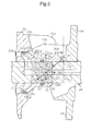
- the movable body-side transmission portion 24d has an arcuate shape the center of which is a point on the rotational axis L of the rotary shaft 17.
- the movable body-side transmission portion 24d is aligned with an imaginary circle R1 the center of which is a point on the rotational axis L of the rotary shaft 17.
- the intersection P1 of a normal L3 to the movable body-side transmission portion 24d and the rotational axis L of the rotary shaft 17 is located in the zone Z1, which is surrounded by the sliding portion 241a.
- the normal L3 matches with the direction of the force F1 that is applied to the movable body-side transmission portion 24d by the swash plate-side transmission portion 19b.
- the intersection P1 coincides with the central point of the imaginary circle R1. That is, the movable body-side transmission portion 24d has an arcuate shape the center of which is the intersection P1.
- the second embodiment achieves the following advantage.
- variable displacement swash plate type compressor according to a third embodiment will now be described with reference to Fig. 7 .
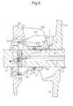
- the movable body 24 has a sliding portion 241 b, which slides along the lug member 23 as the movable body 24 moves along the axis of the rotary shaft 17.
- the clearance S1 between the inner circumferential surface of the first cylindrical portion 24a and the rotary shaft 17 is larger than the clearance S2 between the outer circumferential surface of the second cylindrical portion 24b and the insertion recess 23a. Therefore, the sliding portion 241b is the outer circumferential surface of the second cylindrical portion 24b and extends along the axis of the rotary shaft 17.
- the point at which the perpendicular line L1 to the movable body-side transmission portion 24d intersects the rotational axis L of the rotary shaft 17 as the inclination angle of the swash plate 19 changes is defined as an intersection P2.
- the perpendicular line L1 matches with the direction of a force F1 that is applied to the movable body-side transmission portion 24d by the swash plate-side transmission portion 19b.
- the inclination ⁇ 2 of the movable body-side transmission portion 24d is determined such that, when the inclination angle of the swash plate 19 is maximized, the intersection P2 is located in a zone Z2 surrounded by the sliding portion 241 b when viewed in a direction that is perpendicular to the rotational axis L of the rotary shaft 17 and perpendicular to the first direction (that is, as viewed in the direction that is perpendicular to the sheet of Fig. 7 and directed away from the viewer).
- the inclination ⁇ 2 refers to an inclination with respect to the direction perpendicular to the axis of the rotary shaft 17.
- the intersection P2 is located in the zone Z2 surrounded by the sliding portion 241 b, at which the rotary shaft 17 and the movable body 24 slide on each other in the axial direction of the rotary shaft 17 as the inclination angle of the swash plate 19 changes.
- a resultant force is generated by combining the force F1, which is applied to the movable body-side transmission portion 24d by the swash plate-side transmission portion 19b, a force F2 that is generated by the pressure in the control pressure chamber 27 and acts to move the movable body 24 along the axis of the rotary shaft 17.
- the resultant force is defined as a resultant force F3.
- the resultant force F3 is generated on a vertical line L2 including the intersection P2, and a force F4 that is in the opposite direction and balances with the resultant force F3 is also generated on the vertical line L2.
- all the forces acting on the movable body 24 are generated on the vertical line L2, which includes the intersection P2, and balance out, and no moment is generated that acts to tilt the movable body 24 with respect to the moving direction.
- the inclination angle of the swash plate 19 is changed smoothly.
- the third embodiment achieves advantages equivalent to the advantages (1), (2), (5), and (6) of the first embodiment.
Landscapes
- Engineering & Computer Science (AREA)
- Mechanical Engineering (AREA)
- General Engineering & Computer Science (AREA)
- Manufacturing & Machinery (AREA)
- Compressors, Vaccum Pumps And Other Relevant Systems (AREA)
Applications Claiming Priority (1)
| Application Number | Priority Date | Filing Date | Title |
|---|---|---|---|
| JP2014057750A JP6229565B2 (ja) | 2014-03-20 | 2014-03-20 | 可変容量型斜板式圧縮機 |
Publications (2)
| Publication Number | Publication Date |
|---|---|
| EP2921701A2 true EP2921701A2 (de) | 2015-09-23 |
| EP2921701A3 EP2921701A3 (de) | 2016-03-02 |
Family
ID=52473802
Family Applications (1)
| Application Number | Title | Priority Date | Filing Date |
|---|---|---|---|
| EP15155641.2A Withdrawn EP2921701A3 (de) | 2014-03-20 | 2015-02-18 | Taumelscheibenverdichter mit variabler kapazität |
Country Status (5)
| Country | Link |
|---|---|
| US (1) | US9651035B2 (de) |
| EP (1) | EP2921701A3 (de) |
| JP (1) | JP6229565B2 (de) |
| KR (1) | KR101739639B1 (de) |
| CN (1) | CN104929892B (de) |
Citations (1)
| Publication number | Priority date | Publication date | Assignee | Title |
|---|---|---|---|---|
| JPS52131204A (en) | 1976-04-23 | 1977-11-04 | Borg Warner | Controllers for variable discharge compressors |
Family Cites Families (15)
| Publication number | Priority date | Publication date | Assignee | Title |
|---|---|---|---|---|
| US4061443A (en) * | 1976-12-02 | 1977-12-06 | General Motors Corporation | Variable stroke compressor |
| JPS61145379A (ja) * | 1984-12-17 | 1986-07-03 | Nippon Denso Co Ltd | 可変容量型圧縮機 |
| JPS62225782A (ja) * | 1986-03-27 | 1987-10-03 | Nippon Denso Co Ltd | 可変容量型揺動板式圧縮機 |
| JPH0518355A (ja) * | 1991-07-15 | 1993-01-26 | Toyota Autom Loom Works Ltd | 可変容量型圧縮機 |
| JPH05172052A (ja) | 1991-12-18 | 1993-07-09 | Sanden Corp | 可変容量斜板式圧縮機 |
| JPH05312144A (ja) | 1992-05-08 | 1993-11-22 | Sanden Corp | 可変容量斜板式圧縮機 |
| JPH08105384A (ja) | 1994-10-05 | 1996-04-23 | Sanden Corp | 可変容量斜板式圧縮機 |
| JP4061730B2 (ja) * | 1998-09-02 | 2008-03-19 | 株式会社日本自動車部品総合研究所 | 可変容量斜板型圧縮機 |
| JP3984724B2 (ja) * | 1998-09-10 | 2007-10-03 | 株式会社豊田自動織機 | 容量可変型斜板式圧縮機の制御弁及び斜板式圧縮機 |
| JP2003254231A (ja) * | 2001-12-25 | 2003-09-10 | Toyota Industries Corp | 容量可変型圧縮機 |
| US6939112B2 (en) * | 2002-04-25 | 2005-09-06 | Sanden Corporation | Variable displacement compressors |
| DE10320115A1 (de) * | 2002-05-08 | 2003-11-27 | Sanden Corp | Kompressor |
| JP2006022785A (ja) * | 2004-07-09 | 2006-01-26 | Toyota Industries Corp | 容量可変型圧縮機 |
| JP5519193B2 (ja) | 2009-06-05 | 2014-06-11 | サンデン株式会社 | 可変容量圧縮機 |
| JP5482821B2 (ja) * | 2012-01-19 | 2014-05-07 | 株式会社豊田自動織機 | 斜板式可変容量型圧縮機及び斜板式可変容量型圧縮機におけるソレノイド制御方法 |
-
2014
- 2014-03-20 JP JP2014057750A patent/JP6229565B2/ja not_active Expired - Fee Related
-
2015
- 2015-02-10 CN CN201510069289.7A patent/CN104929892B/zh not_active Expired - Fee Related
- 2015-02-13 KR KR1020150022240A patent/KR101739639B1/ko not_active Expired - Fee Related
- 2015-02-18 EP EP15155641.2A patent/EP2921701A3/de not_active Withdrawn
- 2015-02-19 US US14/626,083 patent/US9651035B2/en not_active Expired - Fee Related
Patent Citations (1)
| Publication number | Priority date | Publication date | Assignee | Title |
|---|---|---|---|---|
| JPS52131204A (en) | 1976-04-23 | 1977-11-04 | Borg Warner | Controllers for variable discharge compressors |
Also Published As
| Publication number | Publication date |
|---|---|
| CN104929892A (zh) | 2015-09-23 |
| US20150267691A1 (en) | 2015-09-24 |
| US9651035B2 (en) | 2017-05-16 |
| JP6229565B2 (ja) | 2017-11-15 |
| KR101739639B1 (ko) | 2017-05-24 |
| JP2015183521A (ja) | 2015-10-22 |
| CN104929892B (zh) | 2017-05-17 |
| KR20150110316A (ko) | 2015-10-02 |
| EP2921701A3 (de) | 2016-03-02 |
Similar Documents
| Publication | Publication Date | Title |
|---|---|---|
| US9518568B2 (en) | Swash plate type variable displacement compressor | |
| US9803628B2 (en) | Compressor with drive and tilt mechanisms located on the same side of a swash plate | |
| CN104755759B (zh) | 容量可变型斜盘式压缩机 | |
| US9726163B2 (en) | Variable displacement swash plate type compressor | |
| US9816498B2 (en) | Variable displacement swash-plate compressor | |
| US9523357B2 (en) | Variable displacement swash plate type compressor | |
| EP3026265B1 (de) | Taumelscheibenverdichter mit variabler verdrängung | |
| EP2921701A2 (de) | Taumelscheibenverdichter mit variabler kapazität | |
| US9850886B2 (en) | Variable displacement swash-plate compressor | |
| US20150275880A1 (en) | Variable displacement swash plate compressor | |
| KR20160064005A (ko) | 가변 용량형 사판식 압축기 | |
| JP2018145878A (ja) | 可変容量型斜板式圧縮機 | |
| JP2016169717A (ja) | 容量可変型斜板式圧縮機 | |
| JP2017160887A (ja) | 可変容量型斜板式圧縮機 | |
| JP2018159277A (ja) | 容量可変型斜板式圧縮機 | |
| JP2014194178A (ja) | 容量可変型斜板式圧縮機 |
Legal Events
| Date | Code | Title | Description |
|---|---|---|---|
| PUAI | Public reference made under article 153(3) epc to a published international application that has entered the european phase |
Free format text: ORIGINAL CODE: 0009012 |
|
| 17P | Request for examination filed |
Effective date: 20150218 |
|
| AK | Designated contracting states |
Kind code of ref document: A2 Designated state(s): AL AT BE BG CH CY CZ DE DK EE ES FI FR GB GR HR HU IE IS IT LI LT LU LV MC MK MT NL NO PL PT RO RS SE SI SK SM TR |
|
| AX | Request for extension of the european patent |
Extension state: BA ME |
|
| PUAL | Search report despatched |
Free format text: ORIGINAL CODE: 0009013 |
|
| AK | Designated contracting states |
Kind code of ref document: A3 Designated state(s): AL AT BE BG CH CY CZ DE DK EE ES FI FR GB GR HR HU IE IS IT LI LT LU LV MC MK MT NL NO PL PT RO RS SE SI SK SM TR |
|
| AX | Request for extension of the european patent |
Extension state: BA ME |
|
| RIC1 | Information provided on ipc code assigned before grant |
Ipc: F04B 27/18 20060101ALI20160126BHEP Ipc: F04B 27/10 20060101AFI20160126BHEP |
|
| 17Q | First examination report despatched |
Effective date: 20170102 |
|
| GRAP | Despatch of communication of intention to grant a patent |
Free format text: ORIGINAL CODE: EPIDOSNIGR1 |
|
| INTG | Intention to grant announced |
Effective date: 20170920 |
|
| GRAJ | Information related to disapproval of communication of intention to grant by the applicant or resumption of examination proceedings by the epo deleted |
Free format text: ORIGINAL CODE: EPIDOSDIGR1 |
|
| GRAL | Information related to payment of fee for publishing/printing deleted |
Free format text: ORIGINAL CODE: EPIDOSDIGR3 |
|
| GRAS | Grant fee paid |
Free format text: ORIGINAL CODE: EPIDOSNIGR3 |
|
| GRAR | Information related to intention to grant a patent recorded |
Free format text: ORIGINAL CODE: EPIDOSNIGR71 |
|
| INTC | Intention to grant announced (deleted) | ||
| RIN1 | Information on inventor provided before grant (corrected) |
Inventor name: YAMAZAKI, YUSUKE Inventor name: SAKAKIBARA, KENGO Inventor name: HONDA, KAZUNARI Inventor name: SUZUKI, TAKAHIRO Inventor name: YAMAMOTO, SHINYA Inventor name: NAKAIMA, HIROYUKI |
|
| INTG | Intention to grant announced |
Effective date: 20180209 |
|
| STAA | Information on the status of an ep patent application or granted ep patent |
Free format text: STATUS: THE APPLICATION IS DEEMED TO BE WITHDRAWN |
|
| 18D | Application deemed to be withdrawn |
Effective date: 20180901 |